EP1645659A1 - Method for repairing machine part, method for forming restored machine part, method for manufacturing machine part, gas turbine engine, electric discharge machine, method for repairing turbine component, and method for forming restored turbine component - Google Patents
Method for repairing machine part, method for forming restored machine part, method for manufacturing machine part, gas turbine engine, electric discharge machine, method for repairing turbine component, and method for forming restored turbine component Download PDFInfo
- Publication number
- EP1645659A1 EP1645659A1 EP04745807A EP04745807A EP1645659A1 EP 1645659 A1 EP1645659 A1 EP 1645659A1 EP 04745807 A EP04745807 A EP 04745807A EP 04745807 A EP04745807 A EP 04745807A EP 1645659 A1 EP1645659 A1 EP 1645659A1
- Authority
- EP
- European Patent Office
- Prior art keywords
- deposition
- machine component
- electrode
- electric discharge
- molded
- Prior art date
- Legal status (The legal status is an assumption and is not a legal conclusion. Google has not performed a legal analysis and makes no representation as to the accuracy of the status listed.)
- Granted
Links
Images







Classifications
-
- B—PERFORMING OPERATIONS; TRANSPORTING
- B23—MACHINE TOOLS; METAL-WORKING NOT OTHERWISE PROVIDED FOR
- B23P—METAL-WORKING NOT OTHERWISE PROVIDED FOR; COMBINED OPERATIONS; UNIVERSAL MACHINE TOOLS
- B23P6/00—Restoring or reconditioning objects
- B23P6/002—Repairing turbine components, e.g. moving or stationary blades, rotors
- B23P6/007—Repairing turbine components, e.g. moving or stationary blades, rotors using only additive methods, e.g. build-up welding
-
- B—PERFORMING OPERATIONS; TRANSPORTING
- B23—MACHINE TOOLS; METAL-WORKING NOT OTHERWISE PROVIDED FOR
- B23H—WORKING OF METAL BY THE ACTION OF A HIGH CONCENTRATION OF ELECTRIC CURRENT ON A WORKPIECE USING AN ELECTRODE WHICH TAKES THE PLACE OF A TOOL; SUCH WORKING COMBINED WITH OTHER FORMS OF WORKING OF METAL
- B23H1/00—Electrical discharge machining, i.e. removing metal with a series of rapidly recurring electrical discharges between an electrode and a workpiece in the presence of a fluid dielectric
-
- B—PERFORMING OPERATIONS; TRANSPORTING
- B23—MACHINE TOOLS; METAL-WORKING NOT OTHERWISE PROVIDED FOR
- B23H—WORKING OF METAL BY THE ACTION OF A HIGH CONCENTRATION OF ELECTRIC CURRENT ON A WORKPIECE USING AN ELECTRODE WHICH TAKES THE PLACE OF A TOOL; SUCH WORKING COMBINED WITH OTHER FORMS OF WORKING OF METAL
- B23H1/00—Electrical discharge machining, i.e. removing metal with a series of rapidly recurring electrical discharges between an electrode and a workpiece in the presence of a fluid dielectric
- B23H1/04—Electrodes specially adapted therefor or their manufacture
- B23H1/06—Electrode material
-
- B—PERFORMING OPERATIONS; TRANSPORTING
- B23—MACHINE TOOLS; METAL-WORKING NOT OTHERWISE PROVIDED FOR
- B23H—WORKING OF METAL BY THE ACTION OF A HIGH CONCENTRATION OF ELECTRIC CURRENT ON A WORKPIECE USING AN ELECTRODE WHICH TAKES THE PLACE OF A TOOL; SUCH WORKING COMBINED WITH OTHER FORMS OF WORKING OF METAL
- B23H9/00—Machining specially adapted for treating particular metal objects or for obtaining special effects or results on metal objects
- B23H9/001—Disintegrating
-
- C—CHEMISTRY; METALLURGY
- C23—COATING METALLIC MATERIAL; COATING MATERIAL WITH METALLIC MATERIAL; CHEMICAL SURFACE TREATMENT; DIFFUSION TREATMENT OF METALLIC MATERIAL; COATING BY VACUUM EVAPORATION, BY SPUTTERING, BY ION IMPLANTATION OR BY CHEMICAL VAPOUR DEPOSITION, IN GENERAL; INHIBITING CORROSION OF METALLIC MATERIAL OR INCRUSTATION IN GENERAL
- C23C—COATING METALLIC MATERIAL; COATING MATERIAL WITH METALLIC MATERIAL; SURFACE TREATMENT OF METALLIC MATERIAL BY DIFFUSION INTO THE SURFACE, BY CHEMICAL CONVERSION OR SUBSTITUTION; COATING BY VACUUM EVAPORATION, BY SPUTTERING, BY ION IMPLANTATION OR BY CHEMICAL VAPOUR DEPOSITION, IN GENERAL
- C23C26/00—Coating not provided for in groups C23C2/00 - C23C24/00
-
- Y—GENERAL TAGGING OF NEW TECHNOLOGICAL DEVELOPMENTS; GENERAL TAGGING OF CROSS-SECTIONAL TECHNOLOGIES SPANNING OVER SEVERAL SECTIONS OF THE IPC; TECHNICAL SUBJECTS COVERED BY FORMER USPC CROSS-REFERENCE ART COLLECTIONS [XRACs] AND DIGESTS
- Y10—TECHNICAL SUBJECTS COVERED BY FORMER USPC
- Y10T—TECHNICAL SUBJECTS COVERED BY FORMER US CLASSIFICATION
- Y10T29/00—Metal working
- Y10T29/49—Method of mechanical manufacture
- Y10T29/49316—Impeller making
- Y10T29/49318—Repairing or disassembling
Definitions
- the present invention relates to a repair method for a machine component, a production method of a restored machine component, a production method of a machine component, a gas turbine engine, an electric spark machine, a repair method for a turbine component and a production method for a restored turbine component.
- a machine component such as a turbine rotor blade applied to a gas turbine engine will be subject to various repairs until coming to the end of its life.
- the repairs are carried out in accordance with the following manner.
- the defect generated at the portion to be repaired of the turbine rotor blade is removed by grinding machining.
- a deposition is formed by cladding by welding at a removed portion from which the defect in the turbine rotor blade is removed.
- a first feature of the present invention is a repair method of a machine component for repairing a portion to be repaired of an electrically conductive machine component and being provided with a removal step of removing a defect generated at the portion to be repaired of the machine component; and a deposition step of forming a porous deposition after finishing the removal step by employing a molded electrode composed of a molded body molded from a powder of a metal, a mixed powder of a powder of a metal and a powder of a ceramic, or the molded body processed with a heat treatment, and generating a pulsing electric discharge between a removed portion from which the defect in the machine component is removed and the molded electrode in an electrically insulating liquid or gas so that a material of the molded electrode or a reaction substance of the material carries out deposition, diffusion and/or welding at the removed portion of the machine component by energy of the electric discharge.
- a second feature of the present invention is a production method for production of a restored machine component from an electrically conductive original machine component and being provided with a removal step of removing a defect generated at a portion to be repaired of the original machine component; and a deposition step of forming a porous deposition after finishing the defect removal step by employing a molded electrode composed of a molded body molded from a powder of a metal, a mixed powder of a powder of a metal and a powder of a ceramic, or the molded body processed with a heat treatment, and generating a pulsing electric discharge between a removed portion from which the defect in the original machine component is removed and the molded electrode in an electrically insulating liquid or gas so that a material of the molded electrode or a reaction substance of the material carries out deposition, diffusion and/or welding at the removed portion of the original machine component by energy of the electric discharge.
- a third feature of the present invention is a production method for producing a machine component provided with an electrically conductive component main body and a porous deposition formed at a portion to be treated of the component main body and being provided with a main body step of forming from the component main body; and a deposition step of forming the deposition after finishing the main body step by employing a molded electrode composed of a molded body molded from a powder of a metal, a mixed powder of a powder of a metal and a powder of a ceramic, or the molded body processed with a heat treatment, and generating a pulsing electric discharge between the portion to be treated of the component main body and the molded electrode in an electrically insulating liquid or gas so that a material of the molded electrode or a reaction substance of the material carries out deposition, diffusion and/or welding at the portion to be treated of the component main body by energy of the electric discharge.
- FF forward direction
- FR rearward direction
- a cross direction is referred to as an X-axis direction
- a horizontal direction is referred to as a Y-axis direction
- a vertical direction is referred to as a Z-axis direction
- a discharge direction denotes a front and back direction with respect to a surface of its form in Fig. 6 and Fig. 11.
- a turbine rotor blade 1 which is a subject of a repair method of a machine component in accordance with a first embodiment will be described hereinafter with reference to Fig. 1 and Fig. 2.
- the turbine rotor blade 1 is one of electrically conductive machine components and, when being repaired, can be re-used in a gas turbine engine 3 of a jet engine or such.
- the turbine rotor blade 1 is provided with a blade 5, a platform 7 formed at a proximal end of the blade 5 and a dovetail 9 formed at the plat form 7.
- the dovetail 9 is engageable with a dovetail slot (not shown) of a turbine disk (not shown) which is a component element of the gas turbine engine 3.
- a tip end portion of the blade 5 is a portion to be treated of the turbine rotor blade 1.
- the electric spark machine 11 in accordance with the first embodiment is a machine employed for the repair method of the machine component in accordance with the first embodiment and such and provided with a bed 13 extending in an X-axis direction and a Y-axis direction and a column 15 extending in an Z-axis. Further, the bed 13 is provided with a table 17 and the table 17 is movable in the X-axis direction by means of drive of an X-axis servo-motor 19 and movable in the Y-axis direction by means of drive of a Y-axis servo-motor 21.
- the table 17 is provided with a processing tank 23 for reserving an electrically insulating liquid S containing alkane hydrocarbons such as oil and, in the processing tank 23, a support plate 25 is provided.
- the support plate 25 is provided with a jig 27 to which a machine component such as the turbine rotor blade 1 or a component main body of the machine component described later is capable of being set. Meanwhile, the jig 27 is electrically connected to an electric power source 29.
- the column 13 is provided with a processing head 31 and the processing head 31 is movable in a Z-axis direction by means of drive of a Z-axis servo-motor 33. Moreover, the processing head 31 is provided with a first holder 39 for supporting a hard molded electrode 37 and, in the vicinity of the first holder 39 in the processing head 31, a second holder 43 for supporting a hard electrode 41 having exhaustion resistance is provided. The first holder 39 and the second holder 43 are electrically connected to the electric power source 29.
- the molded electrode 35 is a molded body molded from powder of an oxidation-resistant metal by means of compression by pressing; or the molded body subject to a heat treatment by a vacuum furnace or such. Meanwhile, instead of molding by compressing, the electrode 35 may be formed by slurry pouring, MIM (Metal Injection Molding), spray forming and such.
- MIM Metal Injection Molding
- the oxidation-resistant metal composing the molded electrode 35 includes nickel alloys such as NiCr, CoNiCrAlY and such and cobalt alloys.
- the molded electrode 35 may be composed of a molded body compressed and molded from mixed powder of powder of the oxidation-resistant metal and powder of a ceramic.
- the hard molded electrode 37 is composed of a molded body molded frommixed powder of an oxidation-resistant metal and powder of a ceramic by means of compression by pressing, or the molded body subject to a heat treatment by a vacuum furnace. Meanwhile, instead of molding by compressing, the hard molded electrode 37 may be formed by slurry pouring, MIM (Metal Injection Molding), spray forming and such.
- MIM Metal Injection Molding
- the oxidation-resistant metal composing the hard molded electrode 37 is the same as the oxidation-resistant metal composing the molded electrode 35 and the ceramic composing the hard molded electrode 37 is any one material or a mixed material of any two or more of cBN, TiC, TiN, TiAlN, TiB 2 , WC, SiC, Si 3 N 4 , Cr 3 C 2 , Al 2 O 3 , ZrO 2 -Y, ZrC, VC and B 4 C.
- the hard molded electrode 37 may be composed of a molded body compressed and molded from powder of an electrically conductive ceramic, or the molded body subj ect to a heat treatment.
- the powder of the electrically conductive ceramic may be produced by adding conductive coatings to surfaces of powder of a ceramic.
- the hard electrode 41 is composed of a solid body of graphite, tungsten alloys or copper alloys.
- the repair method of the machine component in accordance with the first embodiment is a method for repairing a tip end portion of the blade 5 as the portion to be repaired and provided with a (1-1) removal step, a (1-2) thin film step, a (1-3) thin film modification step, a (1-4) deposition step, a (1-5) finish step and a (1-6) hard thin film step.
- the turbine rotor blade 1 as the machine component is set at the jig 27 so as to direct the tip end portion of the blade 5 upward.
- the table 17 is moved in the X-axis direction and the Y-axis direction to position the turbine rotor blade 1 so that a removed portion 5e of the blade 5 is opposed to the molded electrode 35. Meanwhile, there may be a case where the table 17 is only necessary to be moved in the X-axis direction.
- a pulsing electric discharge is generated between the tip end portion of the blade 5 and the hard electrode 41 in an electrically insulating liquid S.
- a defect D such as a crack occurred to the tip end portion of the blade 5 can be removed.
- the electrode as being integral with the processing head 31, is reciprocated in the Z-axis direction by a small travel distance by means of driving the Z-axis servo-motor 33.
- a portion from which the defect D is removed is referred to as a removed portion 5e.
- the table 17 After finishing the (1-1) removal step, by means of driving the X-axis servo-motor 19 and the Y-axis servo-motor 21, the table 17 is moved in the X-axis direction and the Y-axis direction to position the turbine rotor blade 1 so that the removed portion 5e of the blade 5 is opposed to the molded electrode 35. Meanwhile, there may be a case where the table 17 is only necessary to be moved in the X-axis direction.
- a pulsing electric discharge is generated between the removed portion 5e of the blade 5 and the molded electrode 35 in an electrically insulating liquid S.
- a material of the molded electrode 35 or a reaction substance of the material carries out deposition, diffusion and/or welding at the removed portion 5e of the blade 5 and thereby a porous thin film 45 can be gradually formed at the removed portion 5e of the blade 5.
- the molded electrode 35 when generating the pulsing discharge, the molded electrode 35, as being integral with the processing head 31, is reciprocated in the Z-axis direction by a small travel distance by means of a drive of the Z-axis servo-motor 33.
- deposition, diffusion and/or welding means all meanings including “desposition”, “diffusion”, “welding”, “mixed phenomena of deposition and diffusion”, “mixed phenomena of deposition and welding”, “mixed phenomena of diffusion and welding” and “mixed phenomena of deposition, diffusion and welding”.
- the table 17 After finishing the (1-2) thin film step, by means of driving the X-axis servo-motor 19 and the Y-axis servo-motor 21, the table 17 is moved in the X-axis direction and the Y-axis direction to position the turbine rotor blade 1 so that the thin film 45 is opposed to the hard electrode 41. Meanwhile, there may be a case where the table 17 is only necessary to be moved in the X-axis direction.
- a pulsing electric discharge is generated between the porous thin film 45 and the hard electrode 41 in an electrically insulating liquid S.
- the thin film 45 can be changed from a porous state into a high-density state by melting the thin film 45.
- the hard electrode 41 when generating the pulsing discharge, the hard electrode 41, as being integral with the processing head 31, is reciprocated in the Z-axis direction by a small travel distance by means of a drive of the Z-axis servo-motor 33.
- the table 17 After finishing the (1-3) thin film modification step, by means of driving the X-axis servo-motor 19 and the Y-axis servo-motor 21, the table 17 is moved in the X-axis direction and the Y-axis direction to position the turbine rotor blade 1 so that the thin film 45 is opposed to the molded electrode 35. Meanwhile, there may be a case where the table 17 is only necessary to be moved in the X-axis direction.
- a pulsing electric discharge is generated between the thin film 45 and the molded electrode 35 in an electrically insulating liquid S.
- a material of the molded electrode 35 or a reaction substance of the material carries out deposition, diffusion and/or welding at the thin film 45 and thereby a porous deposition 47 can be gradually formed at the thin film 45.
- the molded electrode 35 when generating the pulsing discharge, is reciprocated in the Z-axis direction by a small travel distance by means of a drive of the Z-axis servo-motor 33.
- a shape of the tip end portion of the molded electrode 35 is made slightly larger than a shape of the removed portion 5e of the blade 5. Meanwhile, an amount t by which the molded electrode 35 sticks out is preferably 0.02mm or more and 0.3mm or less.
- the table 17 After finishing the (1-4) deposition step, bymeans of driving the X-axis servo-motor 19 and the Y-axis servo-motor 21, the table 17 is moved in the X-axis direction and the Y-axis direction to position the turbine rotor blade 1 so that the deposition 47 is opposed to the hard electrode 41. Meanwhile, there may be a case where the table 17 is only necessary to be moved in the X-axis direction.
- a pulsing electric discharge is generated between the deposition 47 and the hard electrode 41 in an electrically insulating liquid S.
- a finish machining to required dimension can be carried out so as to make a thickness of the deposition 47 to be a predetermined thickness with forming a high-density thin film 47a at a surface side of the deposition 47 by melting the surface side of the deposition 47.
- the hard electrode 41 when generating the pulsing discharge, the hard electrode 41, as being integral with the processing head 31, is reciprocated in the Z-axis direction by a small travel distance by means of a drive of the Z-axis servo-motor 33.
- the molded electrode 35 is detached from the first holder 39 and the hardmolded electrode 37 is made to be supported by the first holder 39.
- the table 17 is moved in the X-axis direction and the Y-axis direction to position the turbine rotor blade 1 so that the deposition 47 is opposed to the hardmolded electrode 37 . Meanwhile, there may be a case where the table 17 is only necessary to be moved in the X-axis direction.
- a pulsing electric discharge is generated between the deposition 47 and the hardmolded electrode 37 in an electrically insulating liquid S.
- a material of the hard molded electrode 37 or a reaction substance of the material carries out deposition, diffusion and/or welding at the deposition 47 and thereby a hard thin film 49 having abrasiveness can be formed and then the repair of the tip end portion of the blade 5 is finished.
- the abrasiveness means a quality of capability of easily abrading an opposite component.
- repair method of the machine component in accordance with the first embodiment may be modified in view of the embodiment as described below.
- the (1-2) thin film step and the (1-3) thin film modification step can be omitted from the series of the steps in the repair method of the machine component in accordance with the first embodiment or the (1-6) hard thin film step can be omitted.
- a pulsing discharge may be generated in an electrically insulating gas.
- a Si electrode 51 composed of a solid body of Si, a molded body molded from powder of Si by compression by pressing, or the molded body subject to a heat treatment by means of a vacuum furnace or such may be used. Further, in this case, a pulsing electric discharge is generated in an electrically insulating liquid containing alkane hydrocarbons. Meanwhile, the Si electrode 51 may be formed by slurrypouring, MIM (Metal Injection Molding), spray forming and such.
- MIM Metal Injection Molding
- the defect D of the tip end portion of the blade 5 may be removed and the finish machining to required dimension may be carried out so as to make a thickness of the deposition 47 to be a predetermined thickness.
- a peening step to process a surface side of the hard thin film 49 with a peening treatment may be added.
- the deposition 47 is formed by means of the energy of the electric discharge, a range of the deposition 47 can be limited within a range where the electric discharge is generated and hence it is prevented to generate an excessive deposition at a time of forming the deposition 47.
- the deposition 47 is formed by means of energy of the electric discharge and the energy of the electric discharge locally acts on a prominently small part in the removed part 5e of the blade 5, rapid temperature rise of the tip end portion of the blade 5 is prevented at a time of forming the deposition 47.
- a boundary part between the thin film 45 and the blade 5 a boundary part between the deposition 47 and the thin film 45 and a boundary part between the hard thin film 49 and the deposition 47 respectively have structures in which composition ratios grade and hence the hard thin film 49 and the deposition 47 can be firmly combined with a base material of the blade 5 via the thin film 45.
- the surface side of the porous deposition 47 is melted to form the high-density thin film 47a at the surface side of the deposition 47, air permeability of the surface side and a rear side of the deposition 47 is made to be lost so that oxidation resistance of the turbine rotor blade 1 after repair can be increased.
- the range of the deposition 47 can be limited within the range where the electric discharge is generated so that the excessive deposition is prevented from generating at the time of forming the deposition 47, troublesome works after forming the deposition 47 can be reduced and a time required for repairing the tip end portion of the blade 5 can be shortened.
- the steps progress from the (1-1) removal step to the (1-6) hard thin film step by means of the single electric spark machine 11, the time required for the repair can be further shortened.
- the hard thin film 49 and the deposition 47 can be firmly combined with the base material of the blade 5 via the thin film 45, the hard thin film 49 and the deposition 47 become unsusceptible to peeling off from the base material of the blade 5 and hence quality of the turbine rotor blade 1 after the repair can be stabilized.
- the quality of the turbine rotor blade 1 after the repair can be improved.
- the peening step is added after finishing the (1-6) hard thin film step, the fatigue strength of the deposition 47 can be increased and hence the quality of the turbine rotor blade 1 after the repair can be further improved.
- a turbine rotor blade 53 in accordance with the modified example is, like as the turbine rotor blade 1, one of the electrically conductive machine components and re-used in a gas turbine engine 3 by processed with repair.
- the turbine rotor blade 53 in accordance with the modified example is composed of a blade 5, a platform 7, a dovetail 9 and a shroud 55 formed at a tip end portion of the blade 5.
- the shroud 55 is provided with a pair of tip seals 57.
- Tip end portions of the pair of the tip seals 57 in the shroud 55 serve as portions to be treated of the turbine rotor blade 53.
- repair in accordance with the first embodiment may be processed with respect to the pair of the tip seals 57 in the shroud 55 and this modified example also accomplishes operations and functions similar to the operations and the functions of the aforementioned first embodiment.
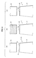
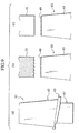
- FIG. 2 A production method of a restored machine component in accordance with a second embodiment will be described hereinafter with reference to Fig. 2, Fig. 3, Fig. 4(a), Fig. 4(b), Fig. 4(c), Fig. 5(a), Fig. 5(b), Fig. 5(c).
- the production method of the restored machine component in accordance with the second embodiment is an invention for production of a restored turbine rotor blade 1B as the restored machine component shown in Fig. 5 (c) from an original turbine rotor blade 1A as an original machine component shown in Fig. 4(a) and, in other words, an invention taken from the repair method of the machine component in accordance with the first embodiment from another viewpoint.
- the production method of the restored machine component in accordance with the second embodiment is also provided with a (2-1) removal step, a (2-2) thin film step, a (2-3) thin film modification step, a (2-4) deposition step, a (2-5) finish step and a (2-6) hard thin film step like as the repair method of the machine component in accordance with the first embodiment.
- the electric spark machine 11, the molded electrode 35, the hard molded electrode 37 and the hard electrode 41 as described above are used.
- the restored turbine rotor blade 1B is used in the gas turbine engine 3 shown in Fig. 2 and rotatable around an axial center of the gas turbine engine 3. Moreover, the tip end portion of the blade 5 serves as a portion to be treated of the original turbine rotor blade 1A.
- the turbine rotor blade 1A as the original machine component is set at the jig 27 so as to direct the tip end portion of the blade 5 upward.
- the table 17 is moved in the X-axis direction and the Y-axis direction to position the turbine rotor blade 1A so that a removed portion 5e of the blade 5 is opposed to the molded electrode 35.
- a pulsing electric discharge is generated between the tip end portion of the blade 5 and the hard electrode 41 in an electrically insulating liquid S.
- a defect D such as a crack occurred to the tip end portion of the blade 5 can be removed. Meanwhile, in the blade 5, a portion from which the defect D is removed is referred to as a removed portion 5e.
- a material of the molded electrode 35 or a reaction substance of the material carries out deposition, diffusion and/or welding at the removed portion 5e of the blade 5 and thereby a porous thin film 45 can be gradually formed at the removed portion 5e of the blade 5.
- the table 17 After finishing the (2-2) thin film step, by means of driving the X-axis servo-motor 19 and the Y-axis servo-motor 21, the table 17 is moved in the X-axis direction and the Y-axis direction to position the original turbine rotor blade 1A so that the thin film 45 is opposed to the hard electrode 41. Further, a pulsing electric discharge is generated between the porous thin film 45 and the hard electrode 41 in an electrically insulating liquid S. Thereby, as shown in Fig. 4(c), by means of energy of the electric discharge, the thin film 45 canbe changed from a porous state into a high-density state by melting the thin film 45.
- the table 17 After finishing the (2-3) thin film modification step, by means of driving the X-axis servo-motor 19 and the Y-axis servo-motor 21, the table 17 is moved in the X-axis direction and the Y-axis direction to position the original turbine rotor blade 1A so that the thin film 45 is opposed to the molded electrode 35. Further, a pulsing electric discharge is generated between the thin film 45 and the molded electrode 35 in an electrically insulating liquid S. Thereby, as shown in Fig.
- a material of the molded electrode 35 or a reaction substance of the material carries out deposition, diffusion and/or welding at the thin film 45 and thereby a porous deposition 47 can be formed at the thin film 45.
- a shape of the tip end portion of the molded electrode 35 is made slightly larger than a shape of the removed portion 5e of the blade 5. Meanwhile, an amount t by which the molded electrode 35 sticks out is preferably 0.02mm or more and 0.3mm or less.
- the table 17 After finishing the (2-4) deposition step, bymeans of driving the X-axis servo-motor 19 and the Y-axis servo-motor 21, the table 17 is moved in the X-axis direction and the Y-axis direction to position the original turbine rotor blade 1A so that the deposition 47 is opposed to the hard electrode 41. Further, a pulsing electric discharge is generated between the deposition 47 and the hard electrode 41 in an electrically insulating liquid S. Thereby, as shown in Fig.
- a finish machining to required dimension can be carried out so as to make a thickness of the deposition 47 to be a predetermined thickness with forming a high-density thin film 47a at a surface side of the deposition 47 by melting the surface side of the deposition 47.
- the molded electrode 35 is detached from the first holder 39 and the hard molded electrode 37 is made to be supported by the first holder 39.
- the table 17 is moved in the X-axis direction and the Y-axis direction to position the original turbine rotor blade 1A so that the deposition 47 is opposed to the hard molded electrode 37. Further, a pulsing electric discharge is generated between the deposition 47 and the hard molded electrode 37 in an electrically insulating liquid S.
- a material of the hard molded electrode 37 or a reaction substance of the material carries out deposition, diffusion and/or welding at the deposition 47 and thereby a hard thin film 49 having abrasiveness can be formed and then the production of the restored turbine rotor blade 1B is finished.
- the production method of the restored machine component may be modified in view of the embodiments like as the repair method of the machine component in accordance with the first embodiment.
- the deposition 47 is formed by means of the energy of the electric discharge, a range of the deposition 47 can be limited within a range where the electric discharge is generated and hence it is prevented to generate an excessive deposition at a time of forming the deposition 47.
- the deposition 47 is formed by means of energy of the electric discharge and the energy of the electric discharge locally acts on a prominently small part in the removed part 5e of the blade 5, rapid temperature rise of the tip end portion of the blade 5 is prevented at a time of forming the deposition 47.
- a boundary part between the thin film 45 and the blade 5 a boundary part between the deposition 47 and the thin film 45 and a boundary part between the hard thin film 49 and the deposition 47 respectively have structures in which composition ratios grade and hence the hard thin film 49 and the deposition 47 can be firmly combined with a base material of the blade 5 via the thin film 45.
- the surface side of the porous deposition 47 is melted to form the high-density thin film 47a at the surface side of the deposition 47, air permeability of the surface side and a rear side of the deposition 47 is made to be lost so that oxidation resistance of the restored turbine rotor blade 1B can be increased.
- the range of the deposition 47 can be limited within the range where the electric discharge is generated so that the excessive deposition is prevented from generating at the time of forming the deposition 47, troublesome works after forming the deposition 47 can be reduced and a time required for the production of the restored turbine rotor blade 1B can be shortened.
- the steps progress from the (2-1) removal step to the (2-6) hard thin film step by means of the single electric sparkmachine 11, the time required for the production canbe further shortened.
- the hard thin film 49 and the deposition 47 can be firmly combined with the base material of the blade 5 via the thin film 45, the hard thin film 49 and the deposition 47 become unsusceptible to peeling off from the base material of the blade 5 and hence quality of the restored turbine rotor blade 1B can be stabilized.
- the quality of the restored turbine rotor blade 1B can be improved.
- the peening step is added after finishing the (2-6) hard thin film step, the fatigue strength of the deposition 47 can be increased and hence the quality of the restored turbine rotor blade 1B can be further improved.
- a turbine rotor blade 59 in accordance with the third embodiment is used in the gas turbine engine 3 and rotatable around the axial center of the gas turbine engine 3.
- the turbine rotor blade 59 is provided with a rotor blade main body 61 as an electrically conductive component main body and the rotor blade main body 61 is composed of a blade 63, a platform 65 formed at a proximal end of the blade 63 and a dovetail 67 formed at the platform 65.
- the dovetail 67 is engageable with the dovetail slot (not shown) of the turbine disk (not shown) as the component element of the gas turbine engine.
- a porous deposition 71 is formed with interposing a thin film 69 and a hard thin film 73 having abrasiveness is formed at the deposition 71.
- the tip end portion of the blade 63 serves as a portion to be treated of the rotor blade main body 61.
- the production method of the machine component in accordance with the third embodiment is a method for production of the turbine rotor blade 59 as the machine component and provided with a (3-1) main body molding step, a (3-2) thin film step, a (3-3) thin film modification step, a (3-4) deposition step, a (3-5) finish step and a (3-6) hard thin film step as described later.
- the electric spark machine, the molded electrode, the hard molded electrode and the hard electrode as described above are used.
- a major part of the rotor blade main body 61 is molded by means of forging or casting. And; the remaining part of the rotor blade main body 61 such as a peripheral shape of the dovetail 67 for example is formed by means of machining such as grinding. Further, a part except the tip end portion of the blade 63 in the rotor blade main body 61 may be subject to formation of an oxidation-resistive coating such as an aluminized coating.
- the rotor blade main body 61 as the component main body is set at the jig 27 so that the tip end portion of the blade 63 is directed upward.
- the table 17 is moved in the X-axis direction and the Y-axis direction to position the rotor blade main body 61 so that the tip end portion of the blade 63 is opposed to the molded electrode 35. Meanwhile, there may be a case where the table 17 is only necessary to be moved in the X-axis direction.
- a pulsing electric discharge is generated between the tip end portion of the blade 63 and the molded electrode 35 in an electrically insulating liquid S.
- a material of the molded electrode 35 or a reaction substance of the material carries out deposition, diffusion and/or welding at the tip end portion of the blade 63 and thereby a porous thin film 69 can be formed at the tip end portion of the blade 63.
- the molded electrode 35 when generating the pulsing discharge, the molded electrode 35, as being integral with the processing head 31, is reciprocated in the Z-axis direction by a small travel distance by means of a drive of the Z-axis servo-motor 33.
- the table 17 After finishing the (3-2) thin film step, by means of driving the X-axis servo-motor 19 and the Y-axis servo-motor 21, the table 17 is moved in the X-axis direction and the Y-axis direction to position the rotor blade main body 61 so that the thin film 69 is opposed to the hard electrode 41. Meanwhile, there may be a case where the table 17 is only necessary to be moved in the X-axis direction.
- a pulsing electric discharge is generated between the porous thin film 69 and the hard electrode 41 in an electrically insulating liquid S.
- the thin film 69 can be changed from a porous state into a high-density state by melting the thin film 69.
- the hard electrode 41 when generating the pulsing discharge, the hard electrode 41, as being integral with the processing head 31, is reciprocated in the Z-axis direction by a small travel distance by means of a drive of the Z-axis servo-motor 33.
- the table 17 After finishing the (3-3) thin film modification step, by means of driving the X-axis servo-motor 19 and the Y-axis servo-motor 21, the table 17 is moved in the X-axis direction and the Y-axis direction to position the rotor blade main body 61 so that the thin film 69 is opposed to the molded electrode 35. Meanwhile, there may be a case where the table 17 is only necessary to be moved in the X-axis direction.
- a pulsing electric discharge is generated between the thin film 69 and the molded electrode 35 in an electrically insulating liquid S.
- a material of the molded electrode 35 or a reaction substance of the material carries out deposition, diffusion and/or welding at the thin film 69 and thereby a porous deposition 71 can be formed at the high-density thin film 69.
- the molded electrode 35 when generating the pulsing discharge, is reciprocated in the Z-axis direction by a small travel distance by means of a drive of the Z-axis servo-motor 33.
- a shape of the tip end portion of the molded electrode 35 is made slightly larger than a shape of the tip end portion of the blade 63. Meanwhile, an amount t by which the molded electrode 35 sticks out is preferably 0.02mm or more and 0.3mm or less.
- the table 17 After finishing the (3-4) deposition step, bymeans of driving the X-axis servo-motor 19 and the Y-axis servo-motor 21, the table 17 is moved in the X-axis direction and the Y-axis direction to position the rotor blade main body 61 so that the deposition 71 is opposed to the hard electrode 41. Meanwhile, there may be a case where the table 17 is only necessary to be moved in the X-axis direction.
- a pulsing electric discharge is generated between the deposition 71 and the hard electrode 41 in an electrically insulating liquid S.
- a finish machining to required dimension can be carried out so as to make a thickness of the deposition 71 to be a predetermined thickness with forming a high-density thin film 71a at a surface side of the deposition 71 by melting the surface side of the deposition 71.
- the hard electrode 41 when generating the pulsing discharge, the hard electrode 41, as being integral with the processing head 31, is reciprocated in the Z-axis direction by a small travel distance by means of a drive of the Z-axis servo-motor 33.
- the molded electrode 35 is detached from the first holder 39 and the hardmolded electrode 37 is made to be supported by the first holder 39.
- the table 17 is moved in the X-axis direction and the Y-axis direction to position the rotor blade main body 61 so that the deposition 71 is opposed to the hardmolded electrode 37. Meanwhile, there may be a case where the table 17 is only necessary to be moved in the X-axis direction.
- a pulsing electric discharge is generated between the deposition 71 and the hardmolded electrode 37 in an electrically insulating liquid S.
- a material of the hard molded electrode 37 or a reaction substance of the material carries out deposition, diffusion and/or welding at the high-density thin film 71a and thereby a hard thin film 73 having abrasiveness can be formed and then the production of the turbine rotor blade 59 is finished.
- the production method of the machine component may be modified in view of the embodiments as described below.
- the (3-1) thin film step and the (3-2) thin film modification step can be omitted from the series of the steps in the repair method of the machine component in accordance with the third embodiment or the (3-6) hard thin film step can be omitted.
- a pulsing discharge may be generated in an electrically insulating gas.
- a Si electrode 51 composed of a solid body of Si, a molded body molded from powder of Si by compression by pressing, or the molded body subject to a heat treatment by means of a vacuum furnace or such may be used. Further, in this case, a pulsing electric discharge is generated in an electrically insulating liquid containing alkane hydrocarbons. Meanwhile, the Si electrode 51 may be formed by slurry pouring, MIM (Metal Injection Molding), spray forming and such.
- MIM Metal Injection Molding
- the finish machining to required dimension may be carried out so as to make a thickness of the deposition 71 to be a predetermined thickness.
- a peening step to process a surface side of the hard thin film 73 with a peening treatment may be added.
- the deposition 71 is formed by means of the energy of the electric discharge, a range of the deposition 71 can be limited within a range where the electric discharge is generated and hence it is prevented to generate an excessive deposition at a time of forming the deposition 71.
- the deposition 71 is formed by means of energy of the electric discharge and the energy of the electric discharge locally acts on a prominently small part in the tip end portion of the blade 63, rapid temperature rise of the tip end portion of the blade 63 is prevented at a time of forming the deposition 71.
- a boundary part between the thin film 69 and the blade 63, a boundary part between the deposition 71 and the thin film 69 and a boundary part between the hard thin film 73 and the deposition 71 respectively have structures in which composition ratios grade and hence the hard thin film 73 and the deposition 71 can be firmly combined with a base material of the blade 63 via the thin film 69.
- the thin film 69 is changed from the porous state into the high-density state by means of the energy of the electric discharge, air permeability of the surface side and a rear side of the deposition 71 is made to be lost so that oxidation resistance of the turbine rotor blade 59 can be increased.
- the range of the deposition 71 can be limited within the range where the electric discharge is generated so that the excessive deposition is prevented from generating at the time of forming the deposition 71, troublesome works after forming the deposition 71 can be reduced and a time required for production of the turbine rotor blade 59 can be shortened.
- the steps progress from the (3-2) thin film step to the (3-6) hard thin film step by means of the single electric spark machine 11, the time required for the production can be further shortened.
- the hard thin film 73 and the deposition 71 can be firmly combined with the base material of the blade 63 via the thin film 69, the hard thin film 73 and the deposition 71 become unsusceptible to peeling off from the base material of the blade 63 and hence quality of the turbine rotor blade 59 can be stabilized.
- the quality of the turbine rotor blade 59 can be improved.
- the peening step is added after finishing the (3-6) hard thin film step, the fatigue strength of the deposition 71 can be increased and hence the quality of the turbine rotor blade 59 can be further improved.
- a turbine rotor blade 75 in accordance with the modified example is, like as the turbine rotor blade 59, used in a gas turbine engine 3 and rotatable around the axial center of the gas turbine engine 3.
- the turbine rotor blade 75 is provided with a rotor blade main body 77 as an electrically conductive component main body and the rotor blade main body 77 is composed of a blade 63, a platform 65, a dovetail 67 and a shroud 79 formed at a tip end portion of the blade 63.
- the shroud 79 is provided with a pair of tip seals 81.
- porous depositions 85 are formed with interposing a high-density thin films 83 and, at the depositions 85, hard thin films 87 having abrasiveness are formed.
- the tip end portions of the pair of the tip seals 81 in the shroud 79 serve as portions to be repaired of the turbine rotor blade 53.
- turbine rotor blade 75 in accordance with the modified example may be also produced by the production method of the machine component in accordance with the third embodiment and the modified example accomplishes operaions and functions similar to the operations and the functions of the aforementioned third embodiment.
- a turbine rotor blade 89 which is a subject of a repair method of a machine component in accordance with a fourth embodiment will be described hereinafter with reference to Fig. 13 and Fig. 2.
- the turbine rotor blade 89 in accordance with the fourth embodiment is one of electrically conductive machine components and, when being repaired, can be re-used in a gas turbine engine 3 of a jet engine or such.
- the turbine rotor blade 89 is provided with a blade 91, a platform 93 formed at a proximal end of the blade 91, a dovetail 95 formed at the platform 93 and a shroud 97 formed at a tip end of the blade 91.
- the dovetail 95 is engageable with a dovetail slot (not shown) of a turbine disk (not shown) which is a component element of the gas turbine engine 3 and the shroud 97 has a pair of abrasion surfaces 97f.
- the abrasion surfaces 97f are easy to have defects (see Fig. 15A) such as cracks caused by abrasion with another abrasion surfaces 97f of the adjacent turbine rotor blade 89' and the pair of the abrasion surfaces 97f in the shroud 97 serve as portions to be treated.
- the electric spark machine 99 in accordance with the fourth embodiment is a machine employed for working of the repair method of the machine component in accordance with the fourth embodiment and provided with a bed 101 extending in an X-axis direction and a Y-axis direction and the bed 101 is provided with a column 103 extending in an Z-axis.
- the bed 101 is provided with a pair of X-axis guides 105 extending in the X-axis direction and the pair of the X-axis guides 105 are provided with a slider 107 to be movable in the X-axis direction by means of driving an X-axis servo-motor 109.
- the slider 107 is provided with a pair of Y-axis guides 111 extending in the Y-axis direction and the pair of the Y-axis guides 111 are provided with a table 113 to be movable in the Y-axis direction by means of driving a Y-axis servo-motor 115. Meanwhile, movement of the slider 107 in the X-axis direction by means of driving the X-axis servo-motor 109 leads to movement of the table 113 in the X-axis direction.
- the table 113 is provided with a processing tank 117 for reserving an electrically insulating liquid S such as oil and, in the processing tank 117, a support plate 119 is provided.
- the support plate 119 is provided with a jig 121 to which a machine component such as the turbine rotor blade 89 or a component main body of the machine component described later is capable of being set. Meanwhile, the jig 121 is electrically connected to an electric power source 123.
- the column 103 is provided with a pair of Z-axis guides 125 extending in the Z-axis direction and the pair of the Z-axis guides 125 are provided with a processing head 127 to be movable in the Z-axis direction by means of driving a Z-axis servo-motor 129.
- the processing head 127 is provided with a first holder 133 for supporting a molded electrode 131 and, in the vicinity of the first holder 133 in the processing head 127, a second holder 137 for supporting a hard electrode 135 having exhaustion resistance is provided:
- the first holder 133 and the second holder 137 are electrically connected to the electric power source 123.
- the molded electrode 131 is a molded body molded from any one powder or two or more powders of powder of a cobalt alloy containing chromium, mixed powder of powder of a cobalt alloy containing chromium, powder of a ceramic and powder of an alloy, powder of Ti or powder of TiC by means of compression by pressing; or the molded body subject to a heat treatment by a vacuum furnace or such. Meanwhile, instead of molding by compressing, the molded electrode 131 may be formed by slurry pouring, MIM (Metal Injection Molding), spray forming and such.
- MIM Metal Injection Molding
- the ceramic composing the molded electrode 131 includes cBN, TiC, TiAlN, AIN, TiB 2 , WC, Cr 3 C 2 , SiC, ZrC, VC, B 4 C, VN, Si 3 N 4 , ZrO 2 -Y, Al 2 O 3 , SiO 2 and such.
- the cobalt alloy containing chromium composing the molded electrode 131 preferably contains Cr in 10% or more and does not contain Ni in 20% or more.
- the hard electrode 135 is composed of a solid body of graphite, tungsten alloys or copper alloys like as the hard electrode 41 in accordance with the first embodiment.
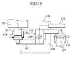
- a replacement unit 139 as shown in Fig. 15 may be used so as to exchange the first holder 133 and the second holder 137 with respect to the processing head 127.
- the bed 101 is provided with a stay 141 in a standing manner and the stay 141 is proided with an arm 143 to be rotatable around a vertical axis 147 by means of driving a replacement servo-motor 145.
- one end of the arm 143 is provided with a first hand 149 for supporting the first holder 133 by grasping and another end of the arm 143 is provided with a second hand 151 for supporting the second holder 137 by grasping.
- the processing head 127 is provided with a grasping mechanism for supporting any holder of the first holder 133 and the second holder 137 by grasping though illustration is omitted.
- the arm 143 is let to rotate around the vertical axis 147 by means of driving the replacement servo-motor 145 so that the empty first hand 149 approaches the processing head 127.
- the holder 133 attached to the processing head 127 is grasped by the first hand 149 and then an attaching state by the processing head 127 is canceled.
- the arm 143 is let to rotate around the vertical axis 147 by means of driving the replacement servo-motor 145 so that the first hand 149 is separated from the processing head 127 as well as the second hand 151 grasping the second holder 137 approaches the processing head 127.
- the second holder 137 is grasped by the second holder 137 and a grasping state by the second hand 151 is canceled. Thereby, the second holder 137 can be replaced for the first holder 133 and attached to the processing head 127.
- the first holder 133 can be replaced for the second holder 137 and attached to the processing head 127.
- the processing head 127 is moved in the Z-axis direction by means of driving the Z-axis servo-motor 127 so that the first holder 133 or the second holder 137 is prevented from interfering the processing head 127.
- the repair method of the machine component in accordance with the fourth embodiment is a method for repairing the pair of the abrasion surfaces 97f in the turbine rotor blade 89 and provided with a (4-1) removal step, a (4-2) deposition step, a (4-3) finish step and a (4-4) repetition step as shown below.
- the turbine rotor blade 89 as the machine component is set at the jig 1115 so as to direct one of the abrasion surfaces 97f in the turbine rotor blade 89 upward.
- the table 113 is moved in the X-axis direction and the Y-axis direction to position the turbine rotor blade 89 so that one of the abrasion surfaces 97f is opposed to the hard electrode 135. Meanwhile, there may be a case where the table 113 is only necessary to be moved in the X-axis direction. Moreover, instead of positioning the turbine rotor blade 89, it may be applicable to replace and attach the second holder 137 for the first holder 133 to the processing head 127 by means of the replacement unit 139.
- a pulsing electric discharge is generated between one of the abrasion surfaces 97f and the hard electrode 135 in an electrically insulating liquid S.
- a defect D such as a crack occurred to one of the abrasion surfaces 97f can be removed.
- the hard electrode 135, as being integral with the processing head 127 is reciprocated in the Z-axis direction by a small travel distance bymeans of driving the Z-axis servo-motor 129.
- a portion from which the defect D is removed is referred to as a removed portion 97e.
- the table 113 After finishing the (4-1) removal step, by means of driving the X-axis servo-motor 109 and the Y-axis servo-motor 115, the table 113 is moved in the X-axis direction and the Y-axis direction to position the turbine rotor blade 89 so that the removed portion 97e of the shroud 97 is opposed to the hard electrode 135. Meanwhile, there may be a case where the table 113 is only necessary to be moved in the X-axis direction. Moreover, instead of positioning the turbine rotor blade 89, it may be applicable to replace and attach the first holder 133 for the second holder 137 to the processing head 127 by means of the replacement unit 139.
- a pulsing electric discharge is generated between the removed portion 97e of the shroud 97 and the molded electrode 131 in an electrically insulating liquid S.
- a material of the hard electrode 131 or a reaction substance of the material carries out deposition, diffusion and/or welding at the removed portion 97e of the shroud 97 and thereby a porous deposition 153 can be formed.
- the molded electrode 131 when generating the pulsing discharge, the molded electrode 131, as being integral with the processing head 127, is reciprocated in the Z-axis direction by a small travel distance by means of a drive of the Z-axis servo-motor 129.
- the table 113 After finishing the (4-2) deposition step, bymeans of driving the X-axis servo-motor 109 and the Y-axis servo-motor 115, the table 113 is moved in the X-axis direction and the Y-axis direction to position the turbine rotor blade 89 so that the deposition 153 is opposed to the hard electrode 135. Meanwhile, there may be a case where the table 113 is only necessary to be moved in the X-axis direction. Moreover, instead of positioning the turbine rotor blade 89, it may be applicable to replace and attach the second holder 137 for the first holder 133 to the processing head 127 by means of the replacement unit 139.
- a pulsing electric discharge is generated between the deposition 153 and the hard electrode 135 in an electrically insulating liquid S.
- a finish machining to required dimension can be carried out so as to make a thickness of the deposition 153 to be a predetermined thickness with forming a high-density thin film 153a at a surface side of the deposition 153 by melting the surface side of the deposition 153.
- the hard electrode 135, as being integral with the processing head 127 is reciprocated in the Z-axis direction by a small travel distance by means of a drive of the Z-axis servo-motor 129.
- the turbine rotor blade 89 is once detached from the jig 121 and the turbine rotor blade 89 is set at the jig 121 so as to direct the other of the abrasion surfaces 97f in the shroud 97 upward. Then, the steps from the (4-2) removal step to the (4-3) finish step are repeated similarly to the above description and then the repair of the pair of the abrasion surfaces 97f in the shroud 97 is finished.
- a pulsing discharge may be generated in an electrically insulating gas.
- a peening step to process a surface side of the deposition 153 with a peening treatment may be added.
- the deposition 153 is formed by means of the energy of the electric discharge, a range of the deposition 153 can be limited within a range where the electric discharge is generated and hence it is prevented to generate an excessive deposition at a time of forming the deposition 153. Moreover, for the same reason, a boundary part between the deposition 153 and a base material of the shroud 97 has a structure in which a composition ratio grades and hence the deposition 153 can be firmly combined with the base material of the shroud 97.
- the deposition 153 is formed by means of energy of the electric discharge and the energy of the electric discharge locally acts on a prominently small part in the removed part 97e of the shroud 97, temperature rise in the vicinity of the abrasion surfaces 97f of the shroud 97 at a time of forming the deposition 153 is sufficiently prevented.
- the range of the deposition 153 can be limited within the range where the electric discharge is generated so that the excessive deposition is prevented from generating at the time of forming the deposition 153, troublesome works after forming the deposition 153 can be reduced and a time required for repairing the pair of the abrasion surfaces 97f in the shroud 97 canbe shortened.
- the steps progress from the (4-1) removal step to the (4-4) repetition step by means of the single electric spark machine 99, the time required for the repair can be further shortened.
- the deposition 153 can be firmly combined with the base material of the shroud 97, the deposition 153 become unsusceptible to peeling off from the base material of the shroud 97 and hence quality of the turbine rotor blade 89 after the repair can be stabilized.
- the fatigue strength of the deposition 153 can be increased and hence the quality of the turbine rotor blade 89 after the repair can be further improved.
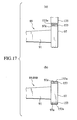
- FIG. 2 A production method of a restored machine component in accordance with a fifth embodiment will be described hereinafter with reference to Fig. 2, from Fig. 13 through Fig. 15, Fig. 16 (a), Fig. 16(b), Fig. 16(c), Fig. 17(a), Fig. 17(b), Fig. 17C.
- the production method of the restored machine component in accordance with the fifth embodiment is an invention for production of a restored turbine rotor blade 89B as the restored machine component shown in Fig. 17 (b) from an original turbine rotor blade 89A as an original machine component shown in Fig. 16 (a) and, in other words, an invention taken from the repair method of the machine component in accordance with the fourth embodiment from another viewpoint.
- the production method of the restored machine component in accordance with the fifth embodiment is also provided with a (5-1) removal step, a (5-2) deposition step, a (5-3) finish step and a (5-4) repetition step like as the repair method of the machine component in accordance with the fourth embodiment.
- the electric spark machine 99, the molded electrode 131 and the hard electrode 135 as described above are used.
- the restored turbine rotor blade 89B is used in the gas turbine engine 3 shown in Fig. 2 and rotatable around an axial center of the gas turbine engine 3. Moreover, the pair of the abrasion surfaces 97f in the shroud 97 serve as portions to be treated of the original turbine rotor blade 89A.
- the original turbine rotor blade 89A as the original machine component is set at the jig 121 so as to direct one of the abrasion surfaces 97f in the original turbine rotor blade 89A upward.
- the turbine rotor blade 89A is positioned so that one of the abrasion surfaces 97f is opposed to the hard electrode 135.
- a pulsing electric discharge is generated between one of the abrasion surfaces 97f and the hard electrode 135 in an electrically insulating liquid S.
- a defect D such as a crack occurred to one of the abrasion surfaces 97f can be removed. Meanwhile, in the shroud 97, a portion from which the defect D is removed is referred to as a removed portion 97e.
- the original turbine rotor blade 89A is positioned so that the removed portion 97e of the shroud 97 is opposed to the molded electrode 131. Further, a pulsing electric discharge is generated between the removed portion 97e of the shroud 97 and the molded electrode 131 in an electrically insulating liquid S.
- a material of the molded electrode 131 or a reaction substance of the material carries out deposition, diffusion and/or welding at the removed portion 97e of the shroud 97 and thereby a porous deposition 153 can be formed.
- the original turbine rotor blade 89A is positioned so that the deposition 153 is opposed to the hard electrode 135. Further, a pulsing electric discharge is generated between the deposition 153 and the hard electrode 135 in an electrically insulating liquid S.
- a finish machining to required dimension can be carried out so as to make a thickness of the deposition 153 to be a predetermined thickness with forming a high-density thin film 153a at a surface side of the deposition 153 by melting the surface side of the deposition 153.
- the original turbine rotor blade 89A is once detached from the jig 121 and the original turbine rotor blade 89A is set at the jig 121 so as to direct the other of the abrasion surfaces 97f in the shroud 97 upward. Then, the steps from the (5-2) removal step to the (5-3) finish step are repeated similarly to the above description and then the production of the restored turbine rotor blade 89B as the restored machine component is finished.
- the production method of the restored machine component may be modified in view of the embodiments like as the repair method of the machine component in accordance with the first embodiment.
- the deposition 153 is formed by means of the energy of the electric discharge, a range of the deposition 153 can be limited within a range where the electric discharge is generated and hence it is prevented to generate an excessive deposition at a time of forming the deposition 153 . Moreover, for the same reason, a boundary part between the deposition 153 and a base material of the shroud 97 has a structure in which a composition ratio grades and hence the deposition 153 can be firmly combined with the base material of the shroud 97.
- the deposition 153 is formed by means of energy of the electric discharge and the energy of the electric discharge locally acts on a prominently small part in the removed part 97e of the shroud 97, temperature rise in the vicinity of the abrasion surfaces 97f of the shroud 97 at a time of forming the deposition 153 is sufficiently prevented.
- the range of the deposition 153 can be limited within the range where the electric discharge is generated so that the excessive deposition is prevented from generating at the time of forming the deposition 153, troublesome works after forming the deposition 153 can be reduced and a time required for production of the restored turbine rotor blade 89B can be shortened.
- the steps progress from the (5-1) removal step to the (5-4) repetition step by means of the single electric spark machine 99, the time required for the production can be further shortened.
- the deposition 153 can be firmly combined with the base material of the shroud 97, the deposition 153 become unsusceptible to peeling off from the base material of the shroud 97 and hence quality of the restored turbine rotor blade 89B can be stabilized.
- the fatigue strength of the deposition 153 can be increased and hence the quality of the restored turbine rotor blade 89B can be further improved.
Landscapes
- Engineering & Computer Science (AREA)
- Mechanical Engineering (AREA)
- Chemical & Material Sciences (AREA)
- Organic Chemistry (AREA)
- Materials Engineering (AREA)
- Metallurgy (AREA)
- Chemical Kinetics & Catalysis (AREA)
- Physics & Mathematics (AREA)
- Thermal Sciences (AREA)
- Manufacturing & Machinery (AREA)
- Other Surface Treatments For Metallic Materials (AREA)
- Electrical Discharge Machining, Electrochemical Machining, And Combined Machining (AREA)
- Butt Welding And Welding Of Specific Article (AREA)
- Turbine Rotor Nozzle Sealing (AREA)
Abstract
Description
- The present invention relates to a repair method for a machine component, a production method of a restored machine component, a production method of a machine component, a gas turbine engine, an electric spark machine, a repair method for a turbine component and a production method for a restored turbine component.
- In general, a machine component such as a turbine rotor blade applied to a gas turbine engine will be subject to various repairs until coming to the end of its life. In a case where a defect such as a crack occurs to a portion to be repaired of the turbine rotor blade, the repairs are carried out in accordance with the following manner.
- More specifically, the defect generated at the portion to be repaired of the turbine rotor blade is removed by grinding machining. Subsequently, a deposition is formed by cladding by welding at a removed portion from which the defect in the turbine rotor blade is removed. Thereby the turbine rotor blade as the machine component can be repaired and, in other words, a restored turbine rotor blade as a restored machine component can be produced from an original turbine rotor blade as an original machine component which is a subject of repair.
- In the meantime, it is not easy to limit a range of the deposition to the removed portion of the machine component by cladding by welding and hence it is unavoidable to generate an excessive deposition by forming the deposition. Therefore, it is necessary to remove the excessive deposition after forming the deposition and there is a problem that a time required for repairing the portion to be repaired of the machine component, in other words, a time required for production of the restored machine component is elongated.
- Meanwhile, the aforementioned problem occurs to production of a newly produced machine component, which includes a step of cladding by welding.
- To solve the aforementioned problem, a first feature of the present invention is a repair method of a machine component for repairing a portion to be repaired of an electrically conductive machine component and being provided with a removal step of removing a defect generated at the portion to be repaired of the machine component; and a deposition step of forming a porous deposition after finishing the removal step by employing a molded electrode composed of a molded body molded from a powder of a metal, a mixed powder of a powder of a metal and a powder of a ceramic, or the molded body processed with a heat treatment, and generating a pulsing electric discharge between a removed portion from which the defect in the machine component is removed and the molded electrode in an electrically insulating liquid or gas so that a material of the molded electrode or a reaction substance of the material carries out deposition, diffusion and/or welding at the removed portion of the machine component by energy of the electric discharge.
- Moreover, a second feature of the present invention is a production method for production of a restored machine component from an electrically conductive original machine component and being provided with a removal step of removing a defect generated at a portion to be repaired of the original machine component; and a deposition step of forming a porous deposition after finishing the defect removal step by employing a molded electrode composed of a molded body molded from a powder of a metal, a mixed powder of a powder of a metal and a powder of a ceramic, or the molded body processed with a heat treatment, and generating a pulsing electric discharge between a removed portion from which the defect in the original machine component is removed and the molded electrode in an electrically insulating liquid or gas so that a material of the molded electrode or a reaction substance of the material carries out deposition, diffusion and/or welding at the removed portion of the original machine component by energy of the electric discharge.
- Furthermore, a third feature of the present invention is a production method for producing a machine component provided with an electrically conductive component main body and a porous deposition formed at a portion to be treated of the component main body and being provided with a main body step of forming from the component main body; and a deposition step of forming the deposition after finishing the main body step by employing a molded electrode composed of a molded body molded from a powder of a metal, a mixed powder of a powder of a metal and a powder of a ceramic, or the molded body processed with a heat treatment, and generating a pulsing electric discharge between the portion to be treated of the component main body and the molded electrode in an electrically insulating liquid or gas so that a material of the molded electrode or a reaction substance of the material carries out deposition, diffusion and/or welding at the portion to be treated of the component main body by energy of the electric discharge.
-
- [Fig. 1] A drawing showing a turbine rotor blade in accordance with a first embodiment.
- [Fig. 2] A schematic drawing of a gas turbine engine in accordance with embodiments.
- [Fig. 3] A drawing showing an electric spark machine in accordance with a first embodiment.
- [Fig. 4] Fig. 4 (a), Fig. 4 (b), Fig. 4 (c) are drawings explaining a repair method of a machine component in accordance with the first embodiment and a production method of a restored machine component in accordance with a second embodiment.
- [Fig. 5] Fig. 5 (a), Fig. 5 (b), Fig. 5 (c) are drawings explaining the repair method of the machine component in accordance with the first embodiment and the production method of the restored machine component in accordance with the second embodiment.
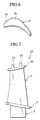
- [Fig. 6] A drawing explaining a relation between a removed portion of a blade and a molded electrode.
- [Fig. 7] A drawing showing a turbine rotor blade in accordance with a modified example of the first embodiment.
- [Fig. 8] A drawing showing a turbine rotor blade in accordance with a third embodiment.
- [Fig. 9] Fig. 9 (a), Fig. 9 (b), Fig. 9 (c) are drawings explaining a production method of a machine component in accordance with the third embodiment.
- [Fig. 10] Fig. 10(a), Fig. 10(b), Fig. 10(c) are drawings explaining the production method of the machine component in accordance with the third embodiment.
- [Fig. 11] A drawing explaining a relation between a tip end portion of the blade and a molded electrode.
- [Fig. 12] A drawing showing a turbine rotor blade in accordance with a modified example of the third embodiment.
- [Fig. 13] A perspective view showing a turbine rotor blade in accordance with a fourth embodiment.
- [Fig. 14] A drawing showing an electric spark machine in accordance with the fourth embodiment.
- [Fig. 15] A schematic plan view of a replacement unit in accordance with the fourth embodiment.
- [Fig. 16] Fig. 16(a), Fig. 16(b), Fig. 16(c) are drawings explaining the repair method of the machine component in accordance with the fourth embodiment and the production method of the restored machine component in accordance with the fifth embodiment.
- [Fig. 17] Fig. 17(a), Fig. 17(b), Fig. 17 (c) are drawings explaining the repair method of the machine component in accordance with the fourth embodiment and the production method of the restored machine component in accordance with the fifth embodiment.
- A description will be hereinafter given to certain embodiments of the present invention for describing the present invention in further detail with appropriate reference to the accompanying drawings. Meanwhile, in the drawings, "FF" denotes a forward direction and "FR" denotes a rearward direction. Moreover, in the description, in proper, "a cross direction" is referred to as an X-axis direction, "a horizontal direction" is referred to as a Y-axis direction and "a vertical direction" is referred to as a Z-axis direction. Furthermore, "a discharge direction" denotes a front and back direction with respect to a surface of its form in Fig. 6 and Fig. 11.
- First, a
turbine rotor blade 1 which is a subject of a repair method of a machine component in accordance with a first embodiment will be described hereinafter with reference to Fig. 1 and Fig. 2. - The
turbine rotor blade 1 is one of electrically conductive machine components and, when being repaired, can be re-used in a gas turbine engine 3 of a jet engine or such. - The
turbine rotor blade 1 is provided with ablade 5, aplatform 7 formed at a proximal end of theblade 5 and adovetail 9 formed at theplat form 7. Here, thedovetail 9 is engageable with a dovetail slot (not shown) of a turbine disk (not shown) which is a component element of the gas turbine engine 3. - Meanwhile, a tip end portion of the
blade 5 is a portion to be treated of theturbine rotor blade 1. - Next, an
electric spark machine 11 employed for a repair method of a machine component in accordance with the first embodiment will be described hereinafter with reference to Fig. 3. - The
electric spark machine 11 in accordance with the first embodiment is a machine employed for the repair method of the machine component in accordance with the first embodiment and such and provided with abed 13 extending in an X-axis direction and a Y-axis direction and acolumn 15 extending in an Z-axis. Further, thebed 13 is provided with a table 17 and the table 17 is movable in the X-axis direction by means of drive of an X-axis servo-motor 19 and movable in the Y-axis direction by means of drive of a Y-axis servo-motor 21. - The table 17 is provided with a
processing tank 23 for reserving an electrically insulating liquid S containing alkane hydrocarbons such as oil and, in theprocessing tank 23, asupport plate 25 is provided. Thesupport plate 25 is provided with ajig 27 to which a machine component such as theturbine rotor blade 1 or a component main body of the machine component described later is capable of being set. Meanwhile, thejig 27 is electrically connected to anelectric power source 29. - The
column 13 is provided with aprocessing head 31 and theprocessing head 31 is movable in a Z-axis direction by means of drive of a Z-axis servo-motor 33. Moreover, theprocessing head 31 is provided with a first holder 39 for supporting a hard moldedelectrode 37 and, in the vicinity of the first holder 39 in theprocessing head 31, asecond holder 43 for supporting ahard electrode 41 having exhaustion resistance is provided. The first holder 39 and thesecond holder 43 are electrically connected to theelectric power source 29. - Here, the molded
electrode 35 is a molded body molded from powder of an oxidation-resistant metal by means of compression by pressing; or the molded body subject to a heat treatment by a vacuum furnace or such. Meanwhile, instead of molding by compressing, theelectrode 35 may be formed by slurry pouring, MIM (Metal Injection Molding), spray forming and such. - Moreover, the oxidation-resistant metal composing the molded
electrode 35 includes nickel alloys such as NiCr, CoNiCrAlY and such and cobalt alloys. Meanwhile, the moldedelectrode 35 may be composed of a molded body compressed and molded from mixed powder of powder of the oxidation-resistant metal and powder of a ceramic. - The hard molded
electrode 37 is composed of a molded body molded frommixed powder of an oxidation-resistant metal and powder of a ceramic by means of compression by pressing, or the molded body subject to a heat treatment by a vacuum furnace. Meanwhile, instead of molding by compressing, the hard moldedelectrode 37 may be formed by slurry pouring, MIM (Metal Injection Molding), spray forming and such. - Moreover, the oxidation-resistant metal composing the hard molded
electrode 37 is the same as the oxidation-resistant metal composing the moldedelectrode 35 and the ceramic composing the hard moldedelectrode 37 is any one material or a mixed material of any two or more of cBN, TiC, TiN, TiAlN, TiB2, WC, SiC, Si3N4, Cr3C2, Al2O3, ZrO2-Y, ZrC, VC and B4C. - Meanwhile, the hard molded
electrode 37 may be composed of a molded body compressed and molded from powder of an electrically conductive ceramic, or the molded body subj ect to a heat treatment. Moreover, the powder of the electrically conductive ceramic may be produced by adding conductive coatings to surfaces of powder of a ceramic. - On the other hand, the
hard electrode 41 is composed of a solid body of graphite, tungsten alloys or copper alloys. - Next, the repair method of the machine component in accordance with the first embodiment will be described hereinafter with reference to Fig. 3, Fig. 4(a), Fig. 4(b), Fig. 5(a), Fig. 5(b), Fig. 5(c) and Fig. 6.
- The repair method of the machine component in accordance with the first embodiment is a method for repairing a tip end portion of the
blade 5 as the portion to be repaired and provided with a (1-1) removal step, a (1-2) thin film step, a (1-3) thin film modification step, a (1-4) deposition step, a (1-5) finish step and a (1-6) hard thin film step. - The
turbine rotor blade 1 as the machine component is set at thejig 27 so as to direct the tip end portion of theblade 5 upward. Next, by means of driving the X-axis servo-motor 19 and the Y-axis servo-motor 21, the table 17 is moved in the X-axis direction and the Y-axis direction to position theturbine rotor blade 1 so that a removedportion 5e of theblade 5 is opposed to the moldedelectrode 35. Meanwhile, there may be a case where the table 17 is only necessary to be moved in the X-axis direction. - Further, a pulsing electric discharge is generated between the tip end portion of the
blade 5 and thehard electrode 41 in an electrically insulating liquid S. Thereby, as shown in Fig. 4(a), by means of energy of the electric discharge, a defect D such as a crack occurred to the tip end portion of theblade 5 can be removed. Meanwhile, when generating the pulsing discharge, the electrode, as being integral with theprocessing head 31, is reciprocated in the Z-axis direction by a small travel distance by means of driving the Z-axis servo-motor 33. Moreover, in theblade 5, a portion from which the defect D is removed is referred to as a removedportion 5e. - After finishing the (1-1) removal step, by means of driving the X-axis servo-
motor 19 and the Y-axis servo-motor 21, the table 17 is moved in the X-axis direction and the Y-axis direction to position theturbine rotor blade 1 so that the removedportion 5e of theblade 5 is opposed to the moldedelectrode 35. Meanwhile, there may be a case where the table 17 is only necessary to be moved in the X-axis direction. - Further, a pulsing electric discharge is generated between the removed
portion 5e of theblade 5 and the moldedelectrode 35 in an electrically insulating liquid S. Thereby, as shown in Fig. 4 (b), by means of energy of the electric discharge, a material of the moldedelectrode 35 or a reaction substance of the material carries out deposition, diffusion and/or welding at the removedportion 5e of theblade 5 and thereby a porousthin film 45 can be gradually formed at the removedportion 5e of theblade 5. Meanwhile, when generating the pulsing discharge, the moldedelectrode 35, as being integral with theprocessing head 31, is reciprocated in the Z-axis direction by a small travel distance by means of a drive of the Z-axis servo-motor 33. - Meanwhile, "deposition, diffusion and/or welding" means all meanings including "desposition", "diffusion", "welding", "mixed phenomena of deposition and diffusion", "mixed phenomena of deposition and welding", "mixed phenomena of diffusion and welding" and "mixed phenomena of deposition, diffusion and welding".
- After finishing the (1-2) thin film step, by means of driving the X-axis servo-
motor 19 and the Y-axis servo-motor 21, the table 17 is moved in the X-axis direction and the Y-axis direction to position theturbine rotor blade 1 so that thethin film 45 is opposed to thehard electrode 41. Meanwhile, there may be a case where the table 17 is only necessary to be moved in the X-axis direction. - Further, a pulsing electric discharge is generated between the porous
thin film 45 and thehard electrode 41 in an electrically insulating liquid S. Thereby, as shown in Fig. 4(c), by means of energy of the electric discharge, thethin film 45 can be changed from a porous state into a high-density state by melting thethin film 45. Meanwhile, when generating the pulsing discharge, thehard electrode 41, as being integral with theprocessing head 31, is reciprocated in the Z-axis direction by a small travel distance by means of a drive of the Z-axis servo-motor 33. - After finishing the (1-3) thin film modification step, by means of driving the X-axis servo-
motor 19 and the Y-axis servo-motor 21, the table 17 is moved in the X-axis direction and the Y-axis direction to position theturbine rotor blade 1 so that thethin film 45 is opposed to the moldedelectrode 35. Meanwhile, there may be a case where the table 17 is only necessary to be moved in the X-axis direction. - Further, a pulsing electric discharge is generated between the
thin film 45 and the moldedelectrode 35 in an electrically insulating liquid S. Thereby, as shown in Fig. 5(a), by means of energy of the electric discharge, a material of the moldedelectrode 35 or a reaction substance of the material carries out deposition, diffusion and/or welding at thethin film 45 and thereby aporous deposition 47 can be gradually formed at thethin film 45. Meanwhile, when generating the pulsing discharge, the moldedelectrode 35, as being integral with theprocessing head 31, is reciprocated in the Z-axis direction by a small travel distance by means of a drive of the Z-axis servo-motor 33. - Here, to exhaust a portion which sticks out of the removed
portion 5e of theblade 5 in a view from the discharge direction as shown in Fig. 6 when the pulsing electric discharge is generated between thethin film 45 and the moldedelectrode 37, a shape of the tip end portion of the moldedelectrode 35 is made slightly larger than a shape of the removedportion 5e of theblade 5. Meanwhile, an amount t by which the moldedelectrode 35 sticks out is preferably 0.02mm or more and 0.3mm or less. - After finishing the (1-4) deposition step, bymeans of driving the X-axis servo-
motor 19 and the Y-axis servo-motor 21, the table 17 is moved in the X-axis direction and the Y-axis direction to position theturbine rotor blade 1 so that thedeposition 47 is opposed to thehard electrode 41. Meanwhile, there may be a case where the table 17 is only necessary to be moved in the X-axis direction. - Further, a pulsing electric discharge is generated between the
deposition 47 and thehard electrode 41 in an electrically insulating liquid S. Thereby, as shown in Fig. 5(b), by means of energy of the electric discharge, a finish machining to required dimension can be carried out so as to make a thickness of thedeposition 47 to be a predetermined thickness with forming a high-densitythin film 47a at a surface side of thedeposition 47 by melting the surface side of thedeposition 47. Meanwhile, when generating the pulsing discharge, thehard electrode 41, as being integral with theprocessing head 31, is reciprocated in the Z-axis direction by a small travel distance by means of a drive of the Z-axis servo-motor 33. - After finishing the (1-5) finish step, the molded
electrode 35 is detached from the first holder 39 and thehardmolded electrode 37 is made to be supported by the first holder 39. Next, by means of driving the X-axis servo-motor 19 and the Y-axis servo-motor 21, the table 17 is moved in the X-axis direction and the Y-axis direction to position theturbine rotor blade 1 so that thedeposition 47 is opposed to thehardmolded electrode 37 . Meanwhile, there may be a case where the table 17 is only necessary to be moved in the X-axis direction. - Further, a pulsing electric discharge is generated between the
deposition 47 and thehardmolded electrode 37 in an electrically insulating liquid S. Thereby, as shown in Fig. 5(c), by means of energy of the electric discharge, a material of the hard moldedelectrode 37 or a reaction substance of the material carries out deposition, diffusion and/or welding at thedeposition 47 and thereby a hardthin film 49 having abrasiveness can be formed and then the repair of the tip end portion of theblade 5 is finished. Meanwhile, the abrasiveness means a quality of capability of easily abrading an opposite component. - Meanwhile, the repair method of the machine component in accordance with the first embodiment may be modified in view of the embodiment as described below.
- More specifically, the (1-2) thin film step and the (1-3) thin film modification step can be omitted from the series of the steps in the repair method of the machine component in accordance with the first embodiment or the (1-6) hard thin film step can be omitted.
- Moreover, instead of generating the pulsing discharge in the electrically insulating liquid S, a pulsing discharge may be generated in an electrically insulating gas.
- Furthermore, instead of the hard molded
electrode 37, as shown in Fig. 5(c), a Si electrode 51 composed of a solid body of Si, a molded body molded from powder of Si by compression by pressing, or the molded body subject to a heat treatment by means of a vacuum furnace or such may be used. Further, in this case, a pulsing electric discharge is generated in an electrically insulating liquid containing alkane hydrocarbons. Meanwhile, the Si electrode 51 may be formed by slurrypouring, MIM (Metal Injection Molding), spray forming and such. - Moreover, by using a grinding lathe instead of the
electric spark machine 11, the defect D of the tip end portion of theblade 5 may be removed and the finish machining to required dimension may be carried out so as to make a thickness of thedeposition 47 to be a predetermined thickness. - Furthermore, after finishing the (1-6) hard thin film step, a peening step to process a surface side of the hard
thin film 49 with a peening treatment may be added. - Next, operations of the first embodiment will be described.
- Because the
deposition 47 is formed by means of the energy of the electric discharge, a range of thedeposition 47 can be limited within a range where the electric discharge is generated and hence it is prevented to generate an excessive deposition at a time of forming thedeposition 47. - Moreover, because the
deposition 47 is formed by means of energy of the electric discharge and the energy of the electric discharge locally acts on a prominently small part in the removedpart 5e of theblade 5, rapid temperature rise of the tip end portion of theblade 5 is prevented at a time of forming thedeposition 47. - Furthermore, because the
thin film 45, thedeposition 47 and the hardthin film 49 are formed by means of the energy of the electric discharge, a boundary part between thethin film 45 and theblade 5, a boundary part between thedeposition 47 and thethin film 45 and a boundary part between the hardthin film 49 and thedeposition 47 respectively have structures in which composition ratios grade and hence the hardthin film 49 and thedeposition 47 can be firmly combined with a base material of theblade 5 via thethin film 45. - Moreover, because, as well as the
thin film 45 is formed at the removedportion 5e of theblade 5 and thethin film 45 is melted to change the porous state into the high-density state by means of the energy of the electric discharge, the surface side of theporous deposition 47 is melted to form the high-densitythin film 47a at the surface side of thedeposition 47, air permeability of the surface side and a rear side of thedeposition 47 is made to be lost so that oxidation resistance of theturbine rotor blade 1 after repair can be increased. - Furthermore, in a case where the peening step is added after finishingthe (1-6) hard thin film step, residual compression stress can be given to the surface side of the
deposition 47 so that a fatigue strength of thedeposition 47 can be increased. - In accordance with the first embodiment as described above, because the range of the
deposition 47 can be limited within the range where the electric discharge is generated so that the excessive deposition is prevented from generating at the time of forming thedeposition 47, troublesome works after forming thedeposition 47 can be reduced and a time required for repairing the tip end portion of theblade 5 can be shortened. In particular, because the steps progress from the (1-1) removal step to the (1-6) hard thin film step by means of the singleelectric spark machine 11, the time required for the repair can be further shortened. - Moreover, because rise in the temperature of the tip end portion of the
blade 5 at the time of forming thedeposition 47 can be sufficiently suppressed, occurrence of fracture at the tip end portion of theblade 5 by thermal contraction is prevented so that defective repair of theturbine rotor blade 1 can be avoided as possible. - Furthermore, because the hard
thin film 49 and thedeposition 47 can be firmly combined with the base material of theblade 5 via thethin film 45, the hardthin film 49 and thedeposition 47 become unsusceptible to peeling off from the base material of theblade 5 and hence quality of theturbine rotor blade 1 after the repair can be stabilized. - Moreover, because oxidation resistance and of the
turbine rotor blade 1 after the repair can be improved, the quality of theturbine rotor blade 1 after the repair can be improved. In particular, in the case where the peening step is added after finishing the (1-6) hard thin film step, the fatigue strength of thedeposition 47 can be increased and hence the quality of theturbine rotor blade 1 after the repair can be further improved. - Furthermore, in a case where the
turbine rotor blade 1 after the repair is applied to the gas turbine engine 3, even if difference in thermal expansion between the base material of theblade 5 and the hardthin film 49 is generated, crack of the hardthin film 49 can be suppressed by means of theporous deposition 47 and, even if the crack occurred to the hardthin film 49, propagation of the crack of the hardthin film 49 to the base material of theblade 5 could be prevented. - A modified example of the first embodiment will be described hereinafter with reference to Fig.7 and Fig. 2.
- A
turbine rotor blade 53 in accordance with the modified example is, like as theturbine rotor blade 1, one of the electrically conductive machine components and re-used in a gas turbine engine 3 by processed with repair. - Moreover, the
turbine rotor blade 53 in accordance with the modified example is composed of ablade 5, aplatform 7, adovetail 9 and ashroud 55 formed at a tip end portion of theblade 5. Here, theshroud 55 is provided with a pair of tip seals 57. - Tip end portions of the pair of the tip seals 57 in the
shroud 55 serve as portions to be treated of theturbine rotor blade 53. - Further, the repair in accordance with the first embodiment may be processed with respect to the pair of the tip seals 57 in the
shroud 55 and this modified example also accomplishes operations and functions similar to the operations and the functions of the aforementioned first embodiment. - A production method of a restored machine component in accordance with a second embodiment will be described hereinafter with reference to Fig. 2, Fig. 3, Fig. 4(a), Fig. 4(b), Fig. 4(c), Fig. 5(a), Fig. 5(b), Fig. 5(c).
- The production method of the restored machine component in accordance with the second embodiment is an invention for production of a restored turbine rotor blade 1B as the restored machine component shown in Fig. 5 (c) from an original turbine rotor blade 1A as an original machine component shown in Fig. 4(a) and, in other words, an invention taken from the repair method of the machine component in accordance with the first embodiment from another viewpoint. Further, the production method of the restored machine component in accordance with the second embodiment is also provided with a (2-1) removal step, a (2-2) thin film step, a (2-3) thin film modification step, a (2-4) deposition step, a (2-5) finish step and a (2-6) hard thin film step like as the repair method of the machine component in accordance with the first embodiment. Moreover, in the productionmethod of the restoredmachine component in accordance with the second embodiment, the
electric spark machine 11, the moldedelectrode 35, the hard moldedelectrode 37 and thehard electrode 41 as described above are used. - Meanwhile, the restored turbine rotor blade 1B is used in the gas turbine engine 3 shown in Fig. 2 and rotatable around an axial center of the gas turbine engine 3. Moreover, the tip end portion of the
blade 5 serves as a portion to be treated of the original turbine rotor blade 1A. - The turbine rotor blade 1A as the original machine component is set at the
jig 27 so as to direct the tip end portion of theblade 5 upward. Next, by means of driving the X-axis servo-motor 19 and the Y-axis servo-motor 21, the table 17 is moved in the X-axis direction and the Y-axis direction to position the turbine rotor blade 1A so that a removedportion 5e of theblade 5 is opposed to the moldedelectrode 35. Further, a pulsing electric discharge is generated between the tip end portion of theblade 5 and thehard electrode 41 in an electrically insulating liquid S. Thereby, as shown in Fig. 4(a), by means of energy of the electric discharge, a defect D such as a crack occurred to the tip end portion of theblade 5 can be removed. Meanwhile, in theblade 5, a portion from which the defect D is removed is referred to as a removedportion 5e. - After finishing the (2-1) removal step, by means of driving the X-axis servo-
motor 19 and the Y-axis servo-motor 21, the table 17 is moved in the X-axis direction and the Y-axis direction to position the original turbine rotor blade 1A so that the removedportion 5e of theblade 5 is opposed to the moldedelectrode 35. Further, a pulsing electric discharge is generated between the removedportion 5e of theblade 5 and the moldedelectrode 35 in an electrically insulating liquid S. Thereby, as shown in Fig. 3B, by means of energy of the electric discharge, a material of the moldedelectrode 35 or a reaction substance of the material carries out deposition, diffusion and/or welding at the removedportion 5e of theblade 5 and thereby a porousthin film 45 can be gradually formed at the removedportion 5e of theblade 5. - After finishing the (2-2) thin film step, by means of driving the X-axis servo-
motor 19 and the Y-axis servo-motor 21, the table 17 is moved in the X-axis direction and the Y-axis direction to position the original turbine rotor blade 1A so that thethin film 45 is opposed to thehard electrode 41. Further, a pulsing electric discharge is generated between the porousthin film 45 and thehard electrode 41 in an electrically insulating liquid S. Thereby, as shown in Fig. 4(c), by means of energy of the electric discharge, thethin film 45 canbe changed from a porous state into a high-density state by melting thethin film 45. - After finishing the (2-3) thin film modification step, by means of driving the X-axis servo-
motor 19 and the Y-axis servo-motor 21, the table 17 is moved in the X-axis direction and the Y-axis direction to position the original turbine rotor blade 1A so that thethin film 45 is opposed to the moldedelectrode 35. Further, a pulsing electric discharge is generated between thethin film 45 and the moldedelectrode 35 in an electrically insulating liquid S. Thereby, as shown in Fig. 5(a), by means of energy of the electric discharge, a material of the moldedelectrode 35 or a reaction substance of the material carries out deposition, diffusion and/or welding at thethin film 45 and thereby aporous deposition 47 can be formed at thethin film 45. - Here, to exhaust a portion which sticks out of the removed
portion 5e of theblade 5 in a view from the discharge direction as shown in Fig. 6 when the pulsing electric discharge is generated between thethin film 45 and the moldedelectrode 37, a shape of the tip end portion of the moldedelectrode 35 is made slightly larger than a shape of the removedportion 5e of theblade 5. Meanwhile, an amount t by which the moldedelectrode 35 sticks out is preferably 0.02mm or more and 0.3mm or less. - After finishing the (2-4) deposition step, bymeans of driving the X-axis servo-
motor 19 and the Y-axis servo-motor 21, the table 17 is moved in the X-axis direction and the Y-axis direction to position the original turbine rotor blade 1A so that thedeposition 47 is opposed to thehard electrode 41. Further, a pulsing electric discharge is generated between thedeposition 47 and thehard electrode 41 in an electrically insulating liquid S. Thereby, as shown in Fig. 5(b), by means of energy of the electric discharge, a finish machining to required dimension can be carried out so as to make a thickness of thedeposition 47 to be a predetermined thickness with forming a high-densitythin film 47a at a surface side of thedeposition 47 by melting the surface side of thedeposition 47. - After finishing the (2-5) finish step, the molded
electrode 35 is detached from the first holder 39 and the hard moldedelectrode 37 is made to be supported by the first holder 39. Next, by means of driving the X-axis servo-motor 19 and the Y-axis servo-motor 21, the table 17 is moved in the X-axis direction and the Y-axis direction to position the original turbine rotor blade 1A so that thedeposition 47 is opposed to the hard moldedelectrode 37. Further, a pulsing electric discharge is generated between thedeposition 47 and the hard moldedelectrode 37 in an electrically insulating liquid S. Thereby, as shown in Fig. 5(c), by means of energy of the electric discharge, a material of the hard moldedelectrode 37 or a reaction substance of the material carries out deposition, diffusion and/or welding at thedeposition 47 and thereby a hardthin film 49 having abrasiveness can be formed and then the production of the restored turbine rotor blade 1B is finished. - Meanwhile, the production method of the restored machine component may be modified in view of the embodiments like as the repair method of the machine component in accordance with the first embodiment.
- Next, operations of the second embodiment will be described.
- Because the
deposition 47 is formed by means of the energy of the electric discharge, a range of thedeposition 47 can be limited within a range where the electric discharge is generated and hence it is prevented to generate an excessive deposition at a time of forming thedeposition 47. - Moreover, because the
deposition 47 is formed by means of energy of the electric discharge and the energy of the electric discharge locally acts on a prominently small part in the removedpart 5e of theblade 5, rapid temperature rise of the tip end portion of theblade 5 is prevented at a time of forming thedeposition 47. - Furthermore, because the
thin film 45, thedeposition 47 and the hardthin film 49 are formed by means of the energy of the electric discharge, a boundary part between thethin film 45 and theblade 5, a boundary part between thedeposition 47 and thethin film 45 and a boundary part between the hardthin film 49 and thedeposition 47 respectively have structures in which composition ratios grade and hence the hardthin film 49 and thedeposition 47 can be firmly combined with a base material of theblade 5 via thethin film 45. - Moreover, because, as well as the
thin film 45 is formed at the removedportion 5e of theblade 5 and thethin film 45 is melted to change the porous state into the high-density state by means of the energy of the electric discharge, the surface side of theporous deposition 47 is melted to form the high-densitythin film 47a at the surface side of thedeposition 47, air permeability of the surface side and a rear side of thedeposition 47 is made to be lost so that oxidation resistance of the restored turbine rotor blade 1B can be increased. - Furthermore, in a case where the peening step is added after finishingthe (2-6) hardthinfilmstep, residualcompressionstress can be given to the surface side of the
deposition 47 so that a fatigue strength of thedeposition 47 can be increased. - In accordance with the first embodiment as described above, because the range of the
deposition 47 can be limited within the range where the electric discharge is generated so that the excessive deposition is prevented from generating at the time of forming thedeposition 47, troublesome works after forming thedeposition 47 can be reduced and a time required for the production of the restored turbine rotor blade 1B can be shortened. In particular, because the steps progress from the (2-1) removal step to the (2-6) hard thin film step by means of the singleelectric sparkmachine 11, the time required for the production canbe further shortened. - Moreover, because the temperature rise of the tip end portion of the
blade 5 at the time of forming thedeposition 47 can be sufficiently suppressed, occurrence of fracture at the tip end portion of theblade 5 by thermal contraction is prevented so that defective production of the restored turbine rotor blade 1B can be avoided as possible. - Furthermore, because the hard
thin film 49 and thedeposition 47 can be firmly combined with the base material of theblade 5 via thethin film 45, the hardthin film 49 and thedeposition 47 become unsusceptible to peeling off from the base material of theblade 5 and hence quality of the restored turbine rotor blade 1B can be stabilized. - Moreover, because oxidation resistance and of the restored turbine rotor blade 1B can be improved, the quality of the restored turbine rotor blade 1B can be improved. In particular, in the case where the peening step is added after finishing the (2-6) hard thin film step, the fatigue strength of the
deposition 47 can be increased and hence the quality of the restored turbine rotor blade 1B can be further improved. - Furthermore, in a case where the restored turbine rotor blade 1B is applied to the gas turbine engine 3, even if difference in thermal expansion between the base material of the
blade 5 and the hardthin film 49 is generated, crack of the hardthin film 49 can be suppressed by means of theporous deposition 47 and, even if the crack occurred to the hardthin film 49, propagation of the crack of the hardthin film 49 to the base material of theblade 5 could be prevented. - First, a
turbine rotor blade 59 in accordance with a third embodiment will be described hereinafter with reference to Fig. 1 and Fig. 8. - A
turbine rotor blade 59 in accordance with the third embodiment is used in the gas turbine engine 3 and rotatable around the axial center of the gas turbine engine 3. Moreover, theturbine rotor blade 59 is provided with a rotor blademain body 61 as an electrically conductive component main body and the rotor blademain body 61 is composed of ablade 63, aplatform 65 formed at a proximal end of theblade 63 and adovetail 67 formed at theplatform 65. Here, thedovetail 67 is engageable with the dovetail slot (not shown) of the turbine disk (not shown) as the component element of the gas turbine engine. At a tip end portion of theblade 63, aporous deposition 71 is formed with interposing athin film 69 and a hardthin film 73 having abrasiveness is formed at thedeposition 71. - Meanwhile, the tip end portion of the
blade 63 serves as a portion to be treated of the rotor blademain body 61. - Next, a production method of a machine component in accordance with the third embodiment will be described hereinafter with reference to Fig. 3, Fig. 9(a), Fig. 9(b), Fig. 9(c), Fig. 10(a), Fig. 10(b) and Fig. 10(c).
- The production method of the machine component in accordance with the third embodiment is a method for production of the
turbine rotor blade 59 as the machine component and provided with a (3-1) main body molding step, a (3-2) thin film step, a (3-3) thin film modification step, a (3-4) deposition step, a (3-5) finish step and a (3-6) hard thin film step as described later. Moreover, in the production method of the machine component in accordance with the third embodiment, the electric spark machine, the molded electrode, the hard molded electrode and the hard electrode as described above are used. - As shown in Fig. 9(a), a major part of the rotor blade
main body 61 is molded by means of forging or casting. And; the remaining part of the rotor blademain body 61 such as a peripheral shape of thedovetail 67 for example is formed by means of machining such as grinding. Further, a part except the tip end portion of theblade 63 in the rotor blademain body 61 may be subject to formation of an oxidation-resistive coating such as an aluminized coating. - The rotor blade
main body 61 as the component main body is set at thejig 27 so that the tip end portion of theblade 63 is directed upward. Next, by means of driving the X-axis servo-motor 19 and the Y-axis servo-motor 21, the table 17 is moved in the X-axis direction and the Y-axis direction to position the rotor blademain body 61 so that the tip end portion of theblade 63 is opposed to the moldedelectrode 35. Meanwhile, there may be a case where the table 17 is only necessary to be moved in the X-axis direction. - Further, a pulsing electric discharge is generated between the tip end portion of the
blade 63 and the moldedelectrode 35 in an electrically insulating liquid S. Thereby, as shown in Fig. 9(b), by means of energy of the electric discharge, a material of the moldedelectrode 35 or a reaction substance of the material carries out deposition, diffusion and/or welding at the tip end portion of theblade 63 and thereby a porousthin film 69 can be formed at the tip end portion of theblade 63. Meanwhile, when generating the pulsing discharge, the moldedelectrode 35, as being integral with theprocessing head 31, is reciprocated in the Z-axis direction by a small travel distance by means of a drive of the Z-axis servo-motor 33. - After finishing the (3-2) thin film step, by means of driving the X-axis servo-
motor 19 and the Y-axis servo-motor 21, the table 17 is moved in the X-axis direction and the Y-axis direction to position the rotor blademain body 61 so that thethin film 69 is opposed to thehard electrode 41. Meanwhile, there may be a case where the table 17 is only necessary to be moved in the X-axis direction. - Further, a pulsing electric discharge is generated between the porous
thin film 69 and thehard electrode 41 in an electrically insulating liquid S. Thereby, as shown in Fig. 9(c), by means of energy of the electric discharge, thethin film 69 can be changed from a porous state into a high-density state by melting thethin film 69. Meanwhile, when generating the pulsing discharge, thehard electrode 41, as being integral with theprocessing head 31, is reciprocated in the Z-axis direction by a small travel distance by means of a drive of the Z-axis servo-motor 33. - After finishing the (3-3) thin film modification step, by means of driving the X-axis servo-
motor 19 and the Y-axis servo-motor 21, the table 17 is moved in the X-axis direction and the Y-axis direction to position the rotor blademain body 61 so that thethin film 69 is opposed to the moldedelectrode 35. Meanwhile, there may be a case where the table 17 is only necessary to be moved in the X-axis direction. - Further, a pulsing electric discharge is generated between the
thin film 69 and the moldedelectrode 35 in an electrically insulating liquid S. Thereby, as shown in Fig. 10(a), by means of energy of the electric discharge, a material of the moldedelectrode 35 or a reaction substance of the material carries out deposition, diffusion and/or welding at thethin film 69 and thereby aporous deposition 71 can be formed at the high-densitythin film 69. Meanwhile, when generating the pulsing discharge, the moldedelectrode 35, as being integral with theprocessing head 31, is reciprocated in the Z-axis direction by a small travel distance by means of a drive of the Z-axis servo-motor 33. - Here, to exhaust a portion which sticks out of the tip end portion of the
blade 63 in a view from the discharge direction as shown in Fig. 11 when the pulsing electric discharge is generated between thethin film 69 and the moldedelectrode 37, a shape of the tip end portion of the moldedelectrode 35 is made slightly larger than a shape of the tip end portion of theblade 63. Meanwhile, an amount t by which the moldedelectrode 35 sticks out is preferably 0.02mm or more and 0.3mm or less. - After finishing the (3-4) deposition step, bymeans of driving the X-axis servo-
motor 19 and the Y-axis servo-motor 21, the table 17 is moved in the X-axis direction and the Y-axis direction to position the rotor blademain body 61 so that thedeposition 71 is opposed to thehard electrode 41. Meanwhile, there may be a case where the table 17 is only necessary to be moved in the X-axis direction. - Further, a pulsing electric discharge is generated between the
deposition 71 and thehard electrode 41 in an electrically insulating liquid S. Thereby, as shown in Fig. 10(b), by means of energy of the electric discharge, a finish machining to required dimension can be carried out so as to make a thickness of thedeposition 71 to be a predetermined thickness with forming a high-densitythin film 71a at a surface side of thedeposition 71 by melting the surface side of thedeposition 71. Meanwhile, when generating the pulsing discharge, thehard electrode 41, as being integral with theprocessing head 31, is reciprocated in the Z-axis direction by a small travel distance by means of a drive of the Z-axis servo-motor 33. - After finishing the (3-5) finish step, the molded
electrode 35 is detached from the first holder 39 and thehardmolded electrode 37 is made to be supported by the first holder 39. Next, by means of driving the X-axis servo-motor 19 and the Y-axis servo-motor 21, the table 17 is moved in the X-axis direction and the Y-axis direction to position the rotor blademain body 61 so that thedeposition 71 is opposed to thehardmolded electrode 37. Meanwhile, there may be a case where the table 17 is only necessary to be moved in the X-axis direction. - Further, a pulsing electric discharge is generated between the
deposition 71 and thehardmolded electrode 37 in an electrically insulating liquid S. Thereby, as shown in Fig. 10(c), by means of energy of the electric discharge, a material of the hard moldedelectrode 37 or a reaction substance of the material carries out deposition, diffusion and/or welding at the high-densitythin film 71a and thereby a hardthin film 73 having abrasiveness can be formed and then the production of theturbine rotor blade 59 is finished. - Meanwhile, the production method of the machine component may be modified in view of the embodiments as described below.
- More specifically, the (3-1) thin film step and the (3-2) thin film modification step can be omitted from the series of the steps in the repair method of the machine component in accordance with the third embodiment or the (3-6) hard thin film step can be omitted.
- Moreover, instead of generating the pulsing discharge in the electrically insulating liquid S, a pulsing discharge may be generated in an electrically insulating gas.
- Furthermore, instead of the hard molded
electrode 37, as shown in Fig. 10(c), a Si electrode 51 composed of a solid body of Si, a molded body molded from powder of Si by compression by pressing, or the molded body subject to a heat treatment by means of a vacuum furnace or such may be used. Further, in this case, a pulsing electric discharge is generated in an electrically insulating liquid containing alkane hydrocarbons. Meanwhile, the Si electrode 51 may be formed by slurry pouring, MIM (Metal Injection Molding), spray forming and such. - Moreover, by using a grinding lathe instead of the
electric spark machine 11, the finish machining to required dimension may be carried out so as to make a thickness of thedeposition 71 to be a predetermined thickness. - Furthermore, after finishing the (3-6) hard thin film step, a peening step to process a surface side of the hard
thin film 73 with a peening treatment may be added. - Next, operations of the third embodiment will be described.
- Because the
deposition 71 is formed by means of the energy of the electric discharge, a range of thedeposition 71 can be limited within a range where the electric discharge is generated and hence it is prevented to generate an excessive deposition at a time of forming thedeposition 71. - Moreover, because the
deposition 71 is formed by means of energy of the electric discharge and the energy of the electric discharge locally acts on a prominently small part in the tip end portion of theblade 63, rapid temperature rise of the tip end portion of theblade 63 is prevented at a time of forming thedeposition 71. - Furthermore, because the
thin film 69, thedeposition 71 and the hardthin film 73 are formed by means of the energy of the electric discharge, a boundary part between thethin film 69 and theblade 63, a boundary part between thedeposition 71 and thethin film 69 and a boundary part between the hardthin film 73 and thedeposition 71 respectively have structures in which composition ratios grade and hence the hardthin film 73 and thedeposition 71 can be firmly combined with a base material of theblade 63 via thethin film 69. - Moreover, because, as well as the high-density
thin film 71a is formed at the surface side of thedeposition 71, thethin film 69 is changed from the porous state into the high-density state by means of the energy of the electric discharge, air permeability of the surface side and a rear side of thedeposition 71 is made to be lost so that oxidation resistance of theturbine rotor blade 59 can be increased. - Furthermore, in a case where the peening step is added after finishingthe (3-6) hardthinfilmstep, residualcompressionstress can be given to the surface side of the
deposition 71 so that a fatigue strength of thedeposition 71 can be increased. - In accordance with the third embodiment as described above, because the range of the
deposition 71 can be limited within the range where the electric discharge is generated so that the excessive deposition is prevented from generating at the time of forming thedeposition 71, troublesome works after forming thedeposition 71 can be reduced and a time required for production of theturbine rotor blade 59 can be shortened. In particular, because the steps progress from the (3-2) thin film step to the (3-6) hard thin film step by means of the singleelectric spark machine 11, the time required for the production can be further shortened. - Moreover, because rise in the temperature of the tip end portion of the
blade 63 at the time of forming thedeposition 71 can be sufficiently suppressed, occurrence of fracture at the tip end portion of theblade 63 by thermal contraction is prevented so that defective production of theturbine rotor blade 59 can be avoided as possible. - Furthermore, because the hard
thin film 73 and thedeposition 71 can be firmly combined with the base material of theblade 63 via thethin film 69, the hardthin film 73 and thedeposition 71 become unsusceptible to peeling off from the base material of theblade 63 and hence quality of theturbine rotor blade 59 can be stabilized. - Moreover, because the air permeability of the surface side and the rear side of the
deposition 71 is made lost to improve oxidation resistance of theturbine rotor blade 59, the quality of theturbine rotor blade 59 can be improved. In particular, in the case where the peening step is added after finishing the (3-6) hard thin film step, the fatigue strength of thedeposition 71 can be increased and hence the quality of theturbine rotor blade 59 can be further improved. - Furthermore, in a case where the
turbine rotor blade 59 is applied to the gas turbine engine 3, even if difference in thermal expansion between the base material of theblade 63 and the hardthin film 73 is generated, crack of the hardthin film 73 can be suppressed by means of theporous deposition 71 and, even if the crack occurred to the hardthin film 73, propagation of the crack of the hardthin film 73 to the base material of theblade 63 could be prevented. - A modified example of the third embodiment will be described hereinafter with reference to Fig. 12 and Fig. 2.
- A
turbine rotor blade 75 in accordance with the modified example is, like as theturbine rotor blade 59, used in a gas turbine engine 3 and rotatable around the axial center of the gas turbine engine 3. - Moreover, the
turbine rotor blade 75 is provided with a rotor blademain body 77 as an electrically conductive component main body and the rotor blademain body 77 is composed of ablade 63, aplatform 65, adovetail 67 and ashroud 79 formed at a tip end portion of theblade 63. Here, theshroud 79 is provided with a pair of tip seals 81. Further, at tip end portions of the respective tip seals 57,porous depositions 85 are formed with interposing a high-densitythin films 83 and, at thedepositions 85, hardthin films 87 having abrasiveness are formed. - Meanwhile, the tip end portions of the pair of the tip seals 81 in the
shroud 79 serve as portions to be repaired of theturbine rotor blade 53. - Further, the
turbine rotor blade 75 in accordance with the modified example may be also produced by the production method of the machine component in accordance with the third embodiment and the modified example accomplishes operaions and functions similar to the operations and the functions of the aforementioned third embodiment. - First, a
turbine rotor blade 89 which is a subject of a repair method of a machine component in accordance with a fourth embodiment will be described hereinafter with reference to Fig. 13 and Fig. 2. - The
turbine rotor blade 89 in accordance with the fourth embodiment is one of electrically conductive machine components and, when being repaired, can be re-used in a gas turbine engine 3 of a jet engine or such. - The
turbine rotor blade 89 is provided with ablade 91, aplatform 93 formed at a proximal end of theblade 91, adovetail 95 formed at theplatform 93 and ashroud 97 formed at a tip end of theblade 91. Here, thedovetail 95 is engageable with a dovetail slot (not shown) of a turbine disk (not shown) which is a component element of the gas turbine engine 3 and theshroud 97 has a pair ofabrasion surfaces 97f. - Meanwhile, the abrasion surfaces 97f are easy to have defects (see Fig. 15A) such as cracks caused by abrasion with another abrasion surfaces 97f of the adjacent turbine rotor blade 89' and the pair of the
abrasion surfaces 97f in theshroud 97 serve as portions to be treated. - Next, an
electric spark machine 99 employed for the repair method of the machine component in accordance with the fourth embodiment will be described hereinafter with reference to Fig. 14. - The
electric spark machine 99 in accordance with the fourth embodiment is a machine employed for working of the repair method of the machine component in accordance with the fourth embodiment and provided with abed 101 extending in an X-axis direction and a Y-axis direction and thebed 101 is provided with acolumn 103 extending in an Z-axis. - The
bed 101 is provided with a pair of X-axis guides 105 extending in the X-axis direction and the pair of the X-axis guides 105 are provided with aslider 107 to be movable in the X-axis direction by means of driving an X-axis servo-motor 109. Moreover, theslider 107 is provided with a pair of Y-axis guides 111 extending in the Y-axis direction and the pair of the Y-axis guides 111 are provided with a table 113 to be movable in the Y-axis direction by means of driving a Y-axis servo-motor 115. Meanwhile, movement of theslider 107 in the X-axis direction by means of driving the X-axis servo-motor 109 leads to movement of the table 113 in the X-axis direction. - The table 113 is provided with a
processing tank 117 for reserving an electrically insulating liquid S such as oil and, in theprocessing tank 117, asupport plate 119 is provided. Thesupport plate 119 is provided with ajig 121 to which a machine component such as theturbine rotor blade 89 or a component main body of the machine component described later is capable of being set. Meanwhile, thejig 121 is electrically connected to anelectric power source 123. - The
column 103 is provided with a pair of Z-axis guides 125 extending in the Z-axis direction and the pair of the Z-axis guides 125 are provided with aprocessing head 127 to be movable in the Z-axis direction by means of driving a Z-axis servo-motor 129. Moreover, theprocessing head 127 is provided with afirst holder 133 for supporting a moldedelectrode 131 and, in the vicinity of thefirst holder 133 in theprocessing head 127, asecond holder 137 for supporting ahard electrode 135 having exhaustion resistance is provided: Thefirst holder 133 and thesecond holder 137 are electrically connected to theelectric power source 123. - Here, the molded
electrode 131 is a molded body molded from any one powder or two or more powders of powder of a cobalt alloy containing chromium, mixed powder of powder of a cobalt alloy containing chromium, powder of a ceramic and powder of an alloy, powder of Ti or powder of TiC by means of compression by pressing; or the molded body subject to a heat treatment by a vacuum furnace or such. Meanwhile, instead of molding by compressing, the moldedelectrode 131 may be formed by slurry pouring, MIM (Metal Injection Molding), spray forming and such. - Moreover, the ceramic composing the molded
electrode 131 includes cBN, TiC, TiAlN, AIN, TiB2, WC, Cr3C2, SiC, ZrC, VC, B4C, VN, Si3N4, ZrO2-Y, Al2O3, SiO2 and such. Meanwhile, the cobalt alloy containing chromium composing the moldedelectrode 131 preferably contains Cr in 10% or more and does not contain Ni in 20% or more. - On the other hand, the
hard electrode 135 is composed of a solid body of graphite, tungsten alloys or copper alloys like as thehard electrode 41 in accordance with the first embodiment. - Meanwhile, instead of that the
processing head 127 is provided with thefirst holder 133 and thesecond holder 137, areplacement unit 139 as shown in Fig. 15 may be used so as to exchange thefirst holder 133 and thesecond holder 137 with respect to theprocessing head 127. - More specifically, as shown in Fig. 15, the
bed 101 is provided with astay 141 in a standing manner and thestay 141 is proided with anarm 143 to be rotatable around avertical axis 147 by means of driving a replacement servo-motor 145. Moreover, one end of thearm 143 is provided with afirst hand 149 for supporting thefirst holder 133 by grasping and another end of thearm 143 is provided with asecond hand 151 for supporting thesecond holder 137 by grasping. Meanwhile, theprocessing head 127 is provided with a grasping mechanism for supporting any holder of thefirst holder 133 and thesecond holder 137 by grasping though illustration is omitted. - Therefore, the
arm 143 is let to rotate around thevertical axis 147 by means of driving the replacement servo-motor 145 so that the emptyfirst hand 149 approaches theprocessing head 127. Next, theholder 133 attached to theprocessing head 127 is grasped by thefirst hand 149 and then an attaching state by theprocessing head 127 is canceled. Further, thearm 143 is let to rotate around thevertical axis 147 by means of driving the replacement servo-motor 145 so that thefirst hand 149 is separated from theprocessing head 127 as well as thesecond hand 151 grasping thesecond holder 137 approaches theprocessing head 127. Further, thesecond holder 137 is grasped by thesecond holder 137 and a grasping state by thesecond hand 151 is canceled. Thereby, thesecond holder 137 can be replaced for thefirst holder 133 and attached to theprocessing head 127. - Moreover, by operations like as the aforementioned, the
first holder 133 can be replaced for thesecond holder 137 and attached to theprocessing head 127. - Meanwhile, when rotating the
arm 143, theprocessing head 127 is moved in the Z-axis direction by means of driving the Z-axis servo-motor 127 so that thefirst holder 133 or thesecond holder 137 is prevented from interfering theprocessing head 127. - Next, the repair method of the machine component in accordance with the fourth embodiment will be described hereinafter with reference to Fig. 14, Fig. 15, Fig. 16(a), Fig. 16(b), Fig. 17 (a) and Fig. 17(b).
- The repair method of the machine component in accordance with the fourth embodiment is a method for repairing the pair of the
abrasion surfaces 97f in theturbine rotor blade 89 and provided with a (4-1) removal step, a (4-2) deposition step, a (4-3) finish step and a (4-4) repetition step as shown below. - The
turbine rotor blade 89 as the machine component is set at the jig 1115 so as to direct one of theabrasion surfaces 97f in theturbine rotor blade 89 upward. - Next, by means of driving the X-axis servo-
motor 109 and the Y-axis servo-motor 115, the table 113 is moved in the X-axis direction and the Y-axis direction to position theturbine rotor blade 89 so that one of theabrasion surfaces 97f is opposed to thehard electrode 135. Meanwhile, there may be a case where the table 113 is only necessary to be moved in the X-axis direction. Moreover, instead of positioning theturbine rotor blade 89, it may be applicable to replace and attach thesecond holder 137 for thefirst holder 133 to theprocessing head 127 by means of thereplacement unit 139. - Further, a pulsing electric discharge is generated between one of the abrasion surfaces 97f and the
hard electrode 135 in an electrically insulating liquid S. Thereby, as shown in Fig. 16(b), by means of energy of the electric discharge, a defect D such as a crack occurred to one of the abrasion surfaces 97f can be removed. Meanwhile, when generating the pulsing discharge, thehard electrode 135, as being integral with theprocessing head 127, is reciprocated in the Z-axis direction by a small travel distance bymeans of driving the Z-axis servo-motor 129. Moreover, in theshroud 97, a portion from which the defect D is removed is referred to as a removedportion 97e. - After finishing the (4-1) removal step, by means of driving the X-axis servo-
motor 109 and the Y-axis servo-motor 115, the table 113 is moved in the X-axis direction and the Y-axis direction to position theturbine rotor blade 89 so that the removedportion 97e of theshroud 97 is opposed to thehard electrode 135. Meanwhile, there may be a case where the table 113 is only necessary to be moved in the X-axis direction. Moreover, instead of positioning theturbine rotor blade 89, it may be applicable to replace and attach thefirst holder 133 for thesecond holder 137 to theprocessing head 127 by means of thereplacement unit 139. - Further, a pulsing electric discharge is generated between the removed
portion 97e of theshroud 97 and the moldedelectrode 131 in an electrically insulating liquid S. Thereby, as shown in Fig. 16(c), by means of energy of the electric discharge, a material of thehard electrode 131 or a reaction substance of the material carries out deposition, diffusion and/or welding at the removedportion 97e of theshroud 97 and thereby aporous deposition 153 can be formed. Meanwhile, when generating the pulsing discharge, the moldedelectrode 131, as being integral with theprocessing head 127, is reciprocated in the Z-axis direction by a small travel distance by means of a drive of the Z-axis servo-motor 129. - After finishing the (4-2) deposition step, bymeans of driving the X-axis servo-
motor 109 and the Y-axis servo-motor 115, the table 113 is moved in the X-axis direction and the Y-axis direction to position theturbine rotor blade 89 so that thedeposition 153 is opposed to thehard electrode 135. Meanwhile, there may be a case where the table 113 is only necessary to be moved in the X-axis direction. Moreover, instead of positioning theturbine rotor blade 89, it may be applicable to replace and attach thesecond holder 137 for thefirst holder 133 to theprocessing head 127 by means of thereplacement unit 139. - Further, a pulsing electric discharge is generated between the
deposition 153 and thehard electrode 135 in an electrically insulating liquid S. Thereby, as shown in Fig. 17(a), by means of energy of the electric discharge, a finish machining to required dimension can be carried out so as to make a thickness of thedeposition 153 to be a predetermined thickness with forming a high-densitythin film 153a at a surface side of thedeposition 153 by melting the surface side of thedeposition 153. Meanwhile, when generating the pulsing discharge, thehard electrode 135, as being integral with theprocessing head 127, is reciprocated in the Z-axis direction by a small travel distance by means of a drive of the Z-axis servo-motor 129. - After finishing the (4-3) finish step, the
turbine rotor blade 89 is once detached from thejig 121 and theturbine rotor blade 89 is set at thejig 121 so as to direct the other of theabrasion surfaces 97f in theshroud 97 upward. Then, the steps from the (4-2) removal step to the (4-3) finish step are repeated similarly to the above description and then the repair of the pair of theabrasion surfaces 97f in theshroud 97 is finished. - Meanwhile, the repair method of the machine component in accordance with the aforementioned fourth embodiment may be modified in view of the embodiments as described below.
- More specifically, instead of generating a pulsing discharge in the electrically insulating liquid S, a pulsing discharge may be generated in an electrically insulating gas.
- Moreover, by using a grinding lathe instead of the
electric spark machine 99, removal of the defect D of the pair of theabrasion surfaces 97f in theshroud 97 or the finish machining to required dimension so as to make a thickness of thedeposition 153 to be a predetermined thickness may be carried out. - Furthermore, after finishing the (4-3) finish step, a peening step to process a surface side of the
deposition 153 with a peening treatment may be added. - Next, operations of the fourth embodiment will be described.
- Because the
deposition 153 is formed by means of the energy of the electric discharge, a range of thedeposition 153 can be limited within a range where the electric discharge is generated and hence it is prevented to generate an excessive deposition at a time of forming thedeposition 153. Moreover, for the same reason, a boundary part between thedeposition 153 and a base material of theshroud 97 has a structure in which a composition ratio grades and hence thedeposition 153 can be firmly combined with the base material of theshroud 97. - Furthermore, in a case where the peening step is added after finishing the (4-3) finish step, residual compression stress can be given to a surface side of the
deposition 153 so that a fatigue strength of thedeposition 153 can be increased. - Moreover, because the
deposition 153 is formed by means of energy of the electric discharge and the energy of the electric discharge locally acts on a prominently small part in the removedpart 97e of theshroud 97, temperature rise in the vicinity of the abrasion surfaces 97f of theshroud 97 at a time of forming thedeposition 153 is sufficiently prevented. - In accordance with the fourth embodiment as described above, because the range of the
deposition 153 can be limited within the range where the electric discharge is generated so that the excessive deposition is prevented from generating at the time of forming thedeposition 153, troublesome works after forming thedeposition 153 can be reduced and a time required for repairing the pair of theabrasion surfaces 97f in theshroud 97 canbe shortened. In particular, because the steps progress from the (4-1) removal step to the (4-4) repetition step by means of the singleelectric spark machine 99, the time required for the repair can be further shortened. - Moreover, because temperature rise in the vicinity of the
abrasion surfaces 97f in theshroud 97 at the time of forming thedeposition 153 can be sufficiently suppressed, occurrence of fracture at theabrasion surfaces 97f in theshroud 97 by thermal contraction is prevented so that defective repair of theturbine rotor blade 89 can be avoided as possible. - Furthermore, because the
deposition 153 can be firmly combined with the base material of theshroud 97, thedeposition 153 become unsusceptible to peeling off from the base material of theshroud 97 and hence quality of theturbine rotor blade 89 after the repair can be stabilized. - Moreover, in the case where the peening step is added after finishing the (4-3) finish step, the fatigue strength of the
deposition 153 can be increased and hence the quality of theturbine rotor blade 89 after the repair can be further improved. - A production method of a restored machine component in accordance with a fifth embodiment will be described hereinafter with reference to Fig. 2, from Fig. 13 through Fig. 15, Fig. 16 (a), Fig. 16(b), Fig. 16(c), Fig. 17(a), Fig. 17(b), Fig. 17C.
- The production method of the restored machine component in accordance with the fifth embodiment is an invention for production of a restored turbine rotor blade 89B as the restored machine component shown in Fig. 17 (b) from an original turbine rotor blade 89A as an original machine component shown in Fig. 16 (a) and, in other words, an invention taken from the repair method of the machine component in accordance with the fourth embodiment from another viewpoint. Further, the production method of the restored machine component in accordance with the fifth embodiment is also provided with a (5-1) removal step, a (5-2) deposition step, a (5-3) finish step and a (5-4) repetition step like as the repair method of the machine component in accordance with the fourth embodiment. Moreover, in the production method of the restoredmachine component in accordance with the fifth embodiment, the
electric spark machine 99, the moldedelectrode 131 and thehard electrode 135 as described above are used. - Meanwhile, the restored turbine rotor blade 89B is used in the gas turbine engine 3 shown in Fig. 2 and rotatable around an axial center of the gas turbine engine 3. Moreover, the pair of the
abrasion surfaces 97f in theshroud 97 serve as portions to be treated of the original turbine rotor blade 89A. - The original turbine rotor blade 89A as the original machine component is set at the
jig 121 so as to direct one of theabrasion surfaces 97f in the original turbine rotor blade 89A upward. Next, by moving the table 113 in the X-axis direction and the Y-axis direction, the turbine rotor blade 89A is positioned so that one of theabrasion surfaces 97f is opposed to thehard electrode 135. Further, a pulsing electric discharge is generated between one of the abrasion surfaces 97f and thehard electrode 135 in an electrically insulating liquid S. Thereby, as shown in Fig. 16(b), by means of energy of the electric discharge, a defect D such as a crack occurred to one of the abrasion surfaces 97f can be removed. Meanwhile, in theshroud 97, a portion from which the defect D is removed is referred to as a removedportion 97e. - After finishing the (5-1) removal step, by moving the table 113 in the X-axis direction and the Y-axis direction, the original turbine rotor blade 89A is positioned so that the removed
portion 97e of theshroud 97 is opposed to the moldedelectrode 131. Further, a pulsing electric discharge is generated between the removedportion 97e of theshroud 97 and the moldedelectrode 131 in an electrically insulating liquid S. Thereby, as shown in Fig. 16(c), by means of energy of the electric discharge, a material of the moldedelectrode 131 or a reaction substance of the material carries out deposition, diffusion and/or welding at the removedportion 97e of theshroud 97 and thereby aporous deposition 153 can be formed. - After finishing the (5-2) deposition step, by moving the table 113 in the X-axis direction and the Y-axis direction, the original turbine rotor blade 89A is positioned so that the
deposition 153 is opposed to thehard electrode 135. Further, a pulsing electric discharge is generated between thedeposition 153 and thehard electrode 135 in an electrically insulating liquid S. Thereby, as shown in Fig. 17(a), by means of energy of the electric discharge, a finish machining to required dimension can be carried out so as to make a thickness of thedeposition 153 to be a predetermined thickness with forming a high-densitythin film 153a at a surface side of thedeposition 153 by melting the surface side of thedeposition 153. - After finishing the (5-3) finish step, the original turbine rotor blade 89A is once detached from the
jig 121 and the original turbine rotor blade 89A is set at thejig 121 so as to direct the other of theabrasion surfaces 97f in theshroud 97 upward. Then, the steps from the (5-2) removal step to the (5-3) finish step are repeated similarly to the above description and then the production of the restored turbine rotor blade 89B as the restored machine component is finished. - Meanwhile, the production method of the restored machine component may be modified in view of the embodiments like as the repair method of the machine component in accordance with the first embodiment.
- Next, operations of the fifth embodiment will be described.
- Because the
deposition 153 is formed by means of the energy of the electric discharge, a range of thedeposition 153 can be limited within a range where the electric discharge is generated and hence it is prevented to generate an excessive deposition at a time of forming thedeposition 153 . Moreover, for the same reason, a boundary part between thedeposition 153 and a base material of theshroud 97 has a structure in which a composition ratio grades and hence thedeposition 153 can be firmly combined with the base material of theshroud 97. - Furthermore, in a case where the peening step is added after finishing the (5-3) finish step, residual compression stress can be given to a surface side of the
deposition 153 so that a fatigue strength of thedeposition 153 can be increased. - Moreover, because the
deposition 153 is formed by means of energy of the electric discharge and the energy of the electric discharge locally acts on a prominently small part in the removedpart 97e of theshroud 97, temperature rise in the vicinity of the abrasion surfaces 97f of theshroud 97 at a time of forming thedeposition 153 is sufficiently prevented. - In accordance with the fifth embodiment as described above, because the range of the
deposition 153 can be limited within the range where the electric discharge is generated so that the excessive deposition is prevented from generating at the time of forming thedeposition 153, troublesome works after forming thedeposition 153 can be reduced and a time required for production of the restored turbine rotor blade 89B can be shortened. In particular, because the steps progress from the (5-1) removal step to the (5-4) repetition step by means of the singleelectric spark machine 99, the time required for the production can be further shortened. - Moreover, because temperature rise in the vicinity of the
abrasion surfaces 97f in theshroud 97 at the time of forming thedeposition 153 can be sufficiently suppressed, occurrence of fracture at theabrasion surfaces 97f in theshroud 97 by thermal contraction is prevented so that defective production of the restored turbine rotor blade 89B can be avoided as possible. - Furthermore, because the
deposition 153 can be firmly combined with the base material of theshroud 97, thedeposition 153 become unsusceptible to peeling off from the base material of theshroud 97 and hence quality of the restored turbine rotor blade 89B can be stabilized. - Moreover, in the case where the peening step is added after finishing the (5-3) finish step, the fatigue strength of the
deposition 153 can be increased and hence the quality of the restored turbine rotor blade 89B can be further improved. - As described above, the invention has been described above by reference to several preferable embodiments, however, the scope of right included in the present invention is not limited to these embodiments.
- Moreover, the contents of Japanese Patent Application No. 2003-167074 filed with the Japan Patent Office on June 11, 2003, the contents of Japanese Patent Application No. 2003-167073 filed with the Japan Patent Office on June 11, 2003 and the contents of Japanese Patent Application No. 2003-167076 filed with the Japan Patent Office on June 11, 2003 should have been cited in the contents of the present application by reference.
Claims (63)
- A repair method of a machine component for repairing a portion to be repaired of an electrically conductive machine component, the repair method of the machine component characterized by comprising:a removal step of removing a defect generated at the portion to be repaired of the machine component; anda deposition step of forming a porous deposition after finishing the removal step by employing a molded electrode composed of a molded body molded from a powder of a metal, a mixed powder of a powder of a metal and a powder of a ceramic, or the molded body processed with a heat treatment, and generating a pulsing electric discharge between a removed portion from which the defect in the machine component is removed and the molded electrode in an electrically insulating liquid or gas so that a material of the molded electrode or a reaction substance of the material carries out deposition, diffusion and/or welding at the removed portion of the machine component by energy of the electric discharge.
- The repair method of the machine component recited in claim 1, characterized by comprising:a finish step of carrying out a finish machining to required dimension after finishing the deposition step so as to make a thickness of the deposition to be a predetermined thickness.
- The repair method of the machine component recited in claim 2, characterized in that, in the finish step, the finish machining to required dimension so as to make the thickness of the deposition to be the predetermined thickness is carried out with forming a high-density thin film at a surface side of the deposition by employing a hard electrode having exhaustion resistance, generating a pulsing electric discharge between the deposition and the hard electrode in an electrically insulating liquid or gas and melting the surface side of the deposition by means of energy of the electric discharge.
- The repair method of the machine component recited in claim 2 or claim 3, characterized by comprising:a peening step of processing a surface side of the deposition with a peening treatment after finishing the finish step.
- The repair method of the machine component recited in any claim from claim 2 to claim 4, characterized by comprising:a hard thin film step of forming a hard thin film having abrasiveness after finishing the finish step by employing a hard molded electrode composed of a molded body molded from a mixed powder of a powder of a metal and a powder of a ceramic or a powder of an electrically conductive ceramic or the molded body processed with a heat treatment, generating a pulsing electric discharge between the deposition and the hard molded electrode in an electrically insulating liquid or gas so that a material of the hard molded electrode or a reaction substance of the material carries out deposition, diffusion and/or welding the thin film in the deposition by energy of the electric discharge.
- The repair method of the machine component recited in any claim from claim 2 to claim 4, characterized by comprising:a hard thin film step of forming a hard thin film having abrasiveness after finishing the finish step by employing a Si electrode composed of a solid body of Si, a molded body molded from a powder of Si by compression by pressing, or the molded body processed with a heat treatment, generating a pulsing electric discharge between the deposition and the Si electrode in an electrically insulating liquid including alkane hydrocarbon so that a material of the Si electrode or a reaction substance of the material carries out deposition, diffusion and/or welding the thin film in the deposition by energy of the electric discharge.
- The repair method of the machine component recited in any claim from claim 2 to claim 6, characterized in that, in the finish step, by employing a hard electrode having exhaustion resistance and generating a pulsing electric discharge between the hard electrode and the portion to be repaired of the machine component in an electrically insulating liquid or gas, the defect generated at the portion to be repaired of the machine component is removed by energy of the electric discharge.
- The repair method of the machine component recited in any claim from claim 1 to claim 7, characterized by comprising:a thin film step of forming a porous thin film after finishing the removal step by employing the molded electrode and generating a pulsing discharge between the removed portion of the machine component and the molded electrode in an electrically insulating liquid or gas so that a material of the molded electrode or a reaction substance of the material carries out deposition, diffusion and/or welding at the removed portion of the machine component by energy of the electric discharge; anda thin film modification step of changing the thin film from a porous state into a high-density state after finishing the thin film step and before starting the deposition step by employing a hard electrode having exhaustion resistance and generating a pulsing electric discharge between the thin film and the hard electrode so that the thin film is melted by means of energy of the electric discharge.
- The repair method of machine component recited in any claim of claim 3, claim 7 and claim 8, characterized in that the hard electrode is composed of a solid boy of graphite, tungsten alloys or copper alloys.
- The repair method of machine component recited in any claim of claim 1 to claim 9, characterized in that a shape of the tip end portion of the molded electrode is-slightly larger than a shape of the removed portion of the machine component so that a portion of the molded electrode which sticks out of the removed portion of the machine component in a view from a discharge direction is exhausted when the pulsing electric discharge is generated between the removed portion of the machine component and the molded electrode.
- The repair method of machine component recited in any claim from claim 1 to claim 10, characterized in that the machine component is an engine component of a gas turbine engine.
- A production method of a restored machine component for production of a restored machine component, the production method of the restored machine component characterized by comprising:a removal step of removing a defect generated at a portion to be treated of the original machine component; anda deposition step of forming a porous deposition after finishing the removal step by employing a molded electrode composed of a molded body molded from a powder of a metal, a mixed powder of a powder of a metal and a powder of a ceramic, or the molded body processed with a heat treatment, and generating a pulsing electric discharge between a removed portion from which the defect in the original machine component is removed and the molded electrode in an electrically insulating liquid or gas so that a material of the molded electrode or a reaction substance of the material carries out deposition, diffusion and/or welding at the removed portion of the original machine component by energy of the electric discharge.
- The production method of the restored machine component recited in claim 12, characterized by comprising:a finish step of carrying out a finish machining to required dimension after finishing the deposition step so as to make a thickness of the deposition to be a predetermined thickness.
- The production method of the restored machine component recited in claim 13, characterized in that, in the finish step, the finish machining to required dimension so as to make the thickness of the deposition to be the predetermined thickness is carried out with forming a high-density thin film at a surface side of the deposition by employing a hard electrode having exhaustion resistance, generating a pulsing electric discharge between the deposition and the hard electrode in an electrically insulating liquid or gas and melting the surface side of the deposition by means of energy of the electric discharge.
- The production method of the restored machine component recited in claim 13 or claim 14, characterized by comprising:a peening step of processing a surface side of the deposition with a peening treatment after finishing the finish step.
- The production method of the restored machine component recited in any claim from claim 13 to claim 15, characterized by comprising:a hard thin film step of forming a hard thin film having abrasiveness after finishing the finish step by employing a hard molded electrode composed of a molded body molded from a mixed powder of a powder of a metal and a powder of a ceramic or a powder of an electrically conductive ceramic or the molded body processed with a heat treatment, generating a pulsing electric discharge between the deposition and the hard molded electrode in an electrically insulating liquid or gas so that a material of the hard molded electrode or a reaction substance of the material carries out deposition, diffusion and/or welding the thin film in the deposition by energy of the electric discharge.
- The production method of the restored machine component recited in any claim from claim 13 to claim 15, characterized by comprising:a hard thin film step of forming a hard thin film having abrasiveness after finishing the finish step by employing a Si electrode composed of a solid body of Si, a molded body molded from a powder of Si by compression by pressing, or the molded body processed with a heat treatment, generating a pulsing electric discharge between the deposition and the Si electrode in an electrically insulating liquid including alkane hydrocarbon so that a material of the Si electrode or a reaction substance of the material carries out deposition, diffusion and/or welding the thin film in the deposition by energy of the electric discharge.
- The production method of the restored machine component recited in any claim from claim 12 to claim 17, characterized in that, in the finish step, by employing a hard electrode having exhaustion resistance and generating a pulsing electric discharge between the hard electrode and the portion to be treated of the original machine component in an electrically insulating liquid or gas, the defect generated at the portion to be treated of the original machine component is removed by energy of the electric discharge.
- The production method of the restored machine component recited in any claim from claim 12 to claim 18, characterized by comprising:a thin film step of forming a porous thin film after finishing the removal step by employing the molded electrode and generating a pulsing discharge between the removed portion of the original machine component and the molded electrode in an electrically insulating liquid or gas so that a material of the molded electrode or a reaction substance of the material carries out deposition, diffusion and/or welding at the removed portion of the original machine component by energy of the electric discharge; anda thin film modification step of changing the thin film from a porous state into a high-density state after finishing the thin film step and before starting the deposition by employing a hard electrode having exhaustion resistance and generating a pulsing electric discharge between the thin film and the hard electrode so that the thin film is melted by means of energy of the electric discharge.
- The production method of the restored machine component recited in any claim from claim 12 to claim 19, characterized in that a cross sectional shape of the molded electrode is slightly larger than an external shape of the portion to be treated of the original machine component so that a portion to be treated of the original machine component so that a portion of the molded electrode which sticks out of the portion to be treated of the original machine component in a view from a discharge direction is exhausted when the pulsing electric discharge is generated between the portion to be treated of the original machine component and the molded electrode.
- The production method of the restored machine component recited in any claim from claim 12 to claim 20, characterized in that the original machine component is an original engine component of a gas turbine engine.
- A production method of a machine component for production of a machine component provided with an electrically conductive component main body, a porous weld body formed at a portion to be treated of the component main body, the production method of the machine component characterized by comprising:a main body step of forming from the component main body;a deposition step of forming a deposition after finishing the removal step by employing a molded electrode composed of a molded body molded from a powder of a metal, a mixed powder of a powder of a metal and a powder of a ceramic, or the molded body processed with a heat treatment, and generating a pulsing electric discharge between a removed portion from which the defect in the machine component is removed and the molded electrode in an electrically insulating liquid or gas so that a material of the molded electrode or a reaction substance of the material carries out deposition, diffusion and/or welding at the removed portion of the machine component by energy of the electric discharge.
- The production method of the machine component recited in claim 22, characterized by comprising:a finish step of carrying out a finish machining to required dimension after finishing the deposition step so as to make a thickness of the deposition to be a predetermined thickness.
- The production method of the machine component recited in claim 23, in the finish step, the finish machining to required dimension so as to make the thickness of the deposition to be the predetermined thickness is carried out with forming a high-density thin film at a surface side of the deposition by employing a hard electrode having exhaustion resistance, generating a pulsing electric discharge between the deposition and the hard electrode in an electrically insulating liquid or gas and melting the surface side of the deposition by means of energy of the electric discharge.
- The production method of the machine component recited in claim 23 or claim 24, characterized by comprising:a peening step of processing a surface side of the deposition with a peening treatment after finishing the finish step.
- The production method of the machine component recited in any claim from claim 22 to claim 25, characterized in that, in the component step, the step is forming from a major part of the component main body by forging or cas ing and forming from a remaining part of the component main body by machining.
- The production method of the machine component recited in any claim from claim 23 to claim 26, characterized by comprising:a hard thin film step of forming a hard thin film having abrasiveness after finishing the finish step by employing a hard molded electrode composed of a molded body molded from a mixed powder of a powder of a metal and a powder of a ceramic or a powder of an electrically conductive ceramic or the molded body subject to a heat treatment, generating a pulsing electric discharge between the deposition and the hard molded electrode in an electrically insulating liquid or gas so that a material of the hard molded electrode or a reaction substance of the material carries out deposition, diffusion and/or welding the thin film in the deposition by energy of the electric discharge.
- The production method of the machine component recited in any claim from claim 23 to claim 26, characterized by comprising:a hard thin film step of forming a hard thin film having abrasiveness after finishing the finish step by employing a Si electrode composed of a solid body of Si, a molded body molded from a powder of Si by compression by pressing, or the molded body processed with a heat treatment, generating a pulsing electric discharge between the deposition and the Si electrode in an electrically insulating liquid including alkane hydrocarbon so that a material of the Si electrode or a reaction substance of the material carries out deposition, diffusion and/or welding the thin film in the deposition by energy of the electric discharge.
- The production method of the machine component recited in any claim from claim 22 to claim 28; characterized by comprising:a thin film step of forming a porous thin film after finishing the main body formation step and before starting the deposition step by employing the molded electrode and generating a pulsing discharge between the portion to be treated of the component main body and the molded electrode in an electrically insulating liquid or gas so that a material of the molded electrode or a reaction substance of the material carries out deposition, diffusion and/or welding at the portion to be treated of the component main body by energy of the electric discharge; anda thin film modification step of changing the thin film from a porous state into a high-density state after finishing the thin film step and before starting the deposition step by employing a hard electrode having exhaustion resistance and generating a pulsing electric discharge between the thin film and the hard electrode so that the thin film is melted by means of energy of the electric discharge.
- The production method of the machine component recited in any claim from claim 22 to claim 29, characterized in that a shape of a tip end portion of the molded electrode is slightly larger than a shape of the portion to be treated of the component main body so that a portion of the molded electrode which sticks out of the portion to be treated of the component main body in a view from a discharge direction is exhausted when the pulsing electric discharge is generated between the portion to be treated of the component main body and the molded electrode.
- The production method of the machine component recited in any claim from claim 22 to claim 30, characterized in that the machine component is an engine component of a gas turbine engine.
- A machine component characterized by being produced by the production method of the machine component recited in any claim from claim 22 to claim 30.
- A machine component characterized by being produced by the production method of the machine component recited in claim 31.
- A gas turbine engine characterized by comprising the machine component recited in claim 34.
- A repair method of a machine component for repairing a portion to be repaired of an electrically conductive machine component, the repair method of the machine component characterized by comprising:a defect removal step of removing a defect generated at the portion to be repaired of the machine component by employing a hard electrode having exhaustion resistance and generating a pulsing electric discharge between the hard electrode and the portion to be repaired of the machine component in an electrically insulating liquid or gas; anda deposition formation step of forming a deposition after finishing the defect removal step by employing a molded electrode composed of a molded body molded from a powder of a metal, a mixed powder of a powder of a metal and a powder of a ceramic, or the molded body processed with a heat treatment, and generating a pulsing electric discharge between a removed portion from which the defect in the machine component is removed and the molded electrode in an electrically insulating liquid or gas so that a material of the molded electrode or a reaction substance of the material carries out deposition, diffusion and/or welding at the removed portion of the machine component by energy of the electric discharge.
- The repair method of the machine component recited in claim 35, characterized by comprising:a finish step of carrying out a finish machining to required dimension after finishing the deposition formation step so as to make a thickness of the deposition to be a predetermined thickness by generating a pulsing electric discharge between the deposition and the hard electrode in an electrically insulating liquid or gas and melting the surface side of the deposition by means of energy of the electric discharge.
- The repair method of the machine component recited in claim 35 or claim 36, characterized in that the hard electrode is composed of graphite, tungsten alloys or copper alloys.
- The repair method of the machine component recited in claim 35 or claim 37, characterized in that the machine component is an engine component of a gas turbine engine.
- A production method of a restored machine component for production of a restored machine component form an electrically conductive original machine component, the production method of the restored machine component characterized by comprsing:a removal step of employing a hard electrode having exhaustion resistance and generating a pulsing electric discharge between the portion to be treated of the original machine component and the hard electrode so that a defect generated at the portion to be treated of the original machine component is removed by means of energy of the electric discharge; anda deposition step of forming a porous deposition after finishing the removal step by employing a molded electrode composed of a molded body molded from a powder of a metal, a mixed powder of a powder of a metal and a powder of a ceramic, or the molded body processed with a heat treatment, and generating a pulsing electric discharge between a removed portion from which the defect in the original machine component is removed and the molded electrode in an electrically insulating liquid or gas so that a material of the molded electrode or a reaction substance of the material carries out deposition, diffusion and/or welding at the removed portion of the original machine component by energy of the electric discharge.
- The production method of the restored machine component recited in claim 39, characterized by comprising:a finish step of carrying out a finish machining to required dimension after finishing the deposition step so as to make a thickness of the deposition to be a predetermined thickness by generating a pulsing electric discharge between the deposition and the hard electrode in an electrically insulating liquid or gas and melting the surface side of the deposition by means of energy of the electric discharge.
- The production method of the restored machine component recited in claim 39 or claim 40, characterized in that the hard electrode is composed of graphite, tungsten alloys or copper alloys.
- The production method of the restored machine component recited in any claim from claim 39 to claim 41, characterized in that the original machine component is an original turbine component of a gas turbine.
- A machine component characterized by being produced by the production method of the original machine component recited in any claim of from claim 12 to claim 20 and from claim 39 to claim 41.
- An original machine component characterized by being produced by the production method of the original machine component recited in claim 21 or claim 42.
- A gas turbine engine characterized by comprising an original machine component recited in claim 44.
- An electric spark machine, in the electric spark machine directly employed in working of the repair method of the machine component recited in claim 35, characterized by comprising:a table;a jig provided at the table, to which the machine component is set;a processing head provided above the table and movable in a vertical direction and a horizontal direction relative to the table;a first holder to support the molded electrode, the first holder being movable integrally with the processing head;a second holder to support the hard electrode, the second holder being movable integrally with the processing head; andan electric power source to generate pulsing electric discharges respectively between a portion to be repaired of the machine component and the hard electrode and between the defect removed portion in the machine component and the molded electrode in an electrically insulating liquid or gas.
- An electric spark machine, in the electric spark machine directly employed in working of the repair method of the machine component recited in claim 35, characterized by comprising:a table;a jig provided at the table, to which the machine component is set;a processing head provided above the table and movable in a vertical direction and a horizontal direction relative to the table;a first holder to support the molded electrode, the first holder being attachable and detachable with respect to the processing head;a second holder to support the hard electrode, the second holder being attachable and detachable with respect to the processing head;a replacement unit to replace the first holder and the second holder with respect to the processing head; andan electric power source to generate pulsing electric discharges respectively between a portion to be repaired of the machine component and the hard electrode and between the defect removed portion in the machine component and the molded electrode in an electrically insulating liquid or gas.
- A repair method of a turbine component for repairing an abrasion surface in the turbine component applied to a gas turbine engine, the repair method of the turbine component characterized by comprising:a removal step of removing a defect generated at the abrasion surface in the turbine component; anda deposition step of forming a deposition having abrasion resistance under a high-temperature environment after finishing the removal step by employing a molded electrode composed of a molded body molded from any one powder or two or more powders of powder of a cobalt alloy containing chromium, mixed powder of powder of a cobalt alloy containing chromium, powder of a ceramic and powder of an alloy, powder of Ti or powder of TiC, or the molded body processed with a heat treatment, and generating a pulsing electric discharge between a removed portion from which the defect in the turbine component is removed and the molded electrode in an electrically insulating liquid or gas so that a material of the molded electrode or a reaction substance of the material carries out deposition, diffusion and/or welding at the removed portion in the turbine component by energy of the electric discharge.
- The repair method of the turbine component recited in claim 48, characterized by comprising:a finish step of carrying out a finish machining to required dimension after finishing the deposition step so as to make a thickness of the deposition to be a predetermined thickness.
- The repair method of the turbine component recited in claim 49, characterized in that, in the finish step, the finish machining to required dimension so as to make the thickness of the deposition to be the predetermined thickness is carried out with forming a high-density thin film at a surface side of the deposition by employing a hard electrode having exhaustion resistance, generating a pulsing electric discharge between the deposition and the hard electrode in an electrically insulating liquid or gas and melting the surface side of the deposition by means of energy of the electric discharge.
- The repair method of the turbine component recited in claim 49 or claim 50, characterized by comprising:a peening step of processing a surface side of the deposition with a peening treatment after finishing the finish step.
- The repair method of the turbine component recited in amy claim from claim 48 to claim 51, characterized in that, in the removal step, by employing a hard electrode having exhaustion resistance and generating a pulsing electric discharge between the abrasion surface in the turbine component and the hard electrode in an electrically insulating liquid or gas, the defect generated at the abrasion surface in the turbine component is removed by energy of the electric discharge.
- The repair method of the turbine component recited in claim 50 or claim 52, characterized in that the hard electrode is graphite, tungsten alloys or copper alloys.
- The repair method of the turbine component recited in amy claim from claim 48 to claim 53, characterized in that the abrasion surface in the turbine component is an abrasion surface in a shroud of a turbine rotor blade.
- A production method of a restored turbine component for production of a restored turbine component from an original turbine component, the production method of the restored turbine component characterized by comprising:a removal step of removing a defect generated at an abrasion surface in the original turbine component; anda deposition step of forming a deposition having abrasion resistance under a high-temperature environment after finishing the removal step by employing a molded electrode composed of a molded body molded from any one powder or two or more powders of powder of a cobalt alloy containing chromium, mixed powder of powder of a cobalt alloy containing chromium, powder of a ceramic and powder of an alloy, powder of Ti or powder of TiC, or the molded body processed with a heat treatment, and generating a pulsing electric discharge between a removed portion from which the defect in the original turbine component is removed and the molded electrode in an electrically insulating liquid or gas so that a material of the molded electrode or a reaction substance of the material carries out deposition, diffusion and/or welding at the removed portion in the original turbine component by energy of the electric discharge.
- The production method of the restored turbine component recited in claim 55, characterized by comprising:a finish step of carrying out a finish machining to required dimension after finishing the deposition step so as to make a thickness of the deposition to be a predetermined thickness.
- The production method of the restored turbine component recited in claim 56, characterized in that, in the finish step, the finish machining to required dimension so as to make the thickness of the deposition to be the predetermined thickness is carried out with forming a high-density thin film at a surface side of the deposition by employing a hard electrode having exhaustion resistance, generating a pulsing electric discharge between the deposition and the hard electrode in an electrically insulating liquid or gas and melting the surface side of the deposition by means of energy of the electric discharge.
- The production method of the restored turbine component recited in claim 56 or claim 57, characterized by comprising:a peening step of processing a surface side of the deposition with a peening treatment after finishing the finish step.
- The production method of the restored turbine component recited in any claim from claim 55 to claim 58, characterized in that, in the removal step, by employing a hard electrode having exhaustion resistance and generating a pulsing electric discharge between the abrasion surface in the original turbine component and the hard electrode in an electrically insulating liquid or gas, the defect generated at the abrasion surface in the original turbine component is removed by energy of the electric discharge.
- The production method of the restored turbine component recited in claim 57 or claim 59, characterized in that the hard electrode is composed of graphite, tungsten alloys or copper alloys.
- The production method of the restored turbine component recited in any claim from claim 55 to claim 60, characterized in that the abrasion surface in the original turbine component is an abrasion surface in a shroud of an original turbine rotor blade.
- A restored turbine component characterized by being produced by the production method of the restored turbine component recited in any claim from claim 55 to claim 61.
- A gas turbine characterized by comprising the restored turbine component recited in claim 62.
Applications Claiming Priority (4)
| Application Number | Priority Date | Filing Date | Title |
|---|---|---|---|
| JP2003167074 | 2003-06-11 | ||
| JP2003167076 | 2003-06-11 | ||
| JP2003167073 | 2003-06-11 | ||
| PCT/JP2004/008213 WO2004111304A1 (en) | 2003-06-11 | 2004-06-11 | Method for repairing machine part, method for forming restored machine part, method for manufacturing machine part, gas turbine engine, electric discharge machine, method for repairing turbine component, and method for forming restored turbine component |
Publications (3)
| Publication Number | Publication Date |
|---|---|
| EP1645659A1 true EP1645659A1 (en) | 2006-04-12 |
| EP1645659A4 EP1645659A4 (en) | 2008-09-17 |
| EP1645659B1 EP1645659B1 (en) | 2011-12-07 |
Family
ID=33556141
Family Applications (1)
| Application Number | Title | Priority Date | Filing Date |
|---|---|---|---|
| EP04745807A Expired - Lifetime EP1645659B1 (en) | 2003-06-11 | 2004-06-11 | Method for repairing machine part, method for forming restored machine part, method for manufacturing machine part, gas turbine engine, electric discharge machine, method for repairing turbine component, and method for forming restored turbine component |
Country Status (8)
| Country | Link |
|---|---|
| US (1) | US7723636B2 (en) |
| EP (1) | EP1645659B1 (en) |
| JP (2) | JP4445923B2 (en) |
| CN (1) | CN1826431B (en) |
| CA (1) | CA2528893C (en) |
| SG (1) | SG155059A1 (en) |
| TW (1) | TWI286955B (en) |
| WO (1) | WO2004111304A1 (en) |
Cited By (7)
| Publication number | Priority date | Publication date | Assignee | Title |
|---|---|---|---|---|
| WO2009023512A1 (en) * | 2007-08-14 | 2009-02-19 | Card-Monroe Corporation | Replaceable looper/hook modules |
| EP2141262A4 (en) * | 2007-03-26 | 2011-07-13 | Ihi Corp | Heat resistant component |
| US7997219B2 (en) | 2007-08-20 | 2011-08-16 | Card-Monroe Corp. | System and method for facilitating removal of gauge parts from hook bar modules |
| EP2255911A3 (en) * | 2009-05-28 | 2012-10-31 | General Electric Company | Electric Discharge Machining Die Sinking Device |
| EP2420594A4 (en) * | 2009-04-14 | 2013-11-13 | Ihi Corp | SURFACE-PROCESSING ELECTRODE BY DISCHARGE AND METHOD FOR MANUFACTURING THE SAME |
| EP3034809A1 (en) * | 2014-12-16 | 2016-06-22 | United Technologies Corporation | Gas turbine engine component with abrasive surface formed by electrical discharge machining |
| US12054868B2 (en) | 2021-06-21 | 2024-08-06 | Card-Monroe Corp. | Tufting machine and method of tufting |
Families Citing this family (26)
| Publication number | Priority date | Publication date | Assignee | Title |
|---|---|---|---|---|
| US9284647B2 (en) | 2002-09-24 | 2016-03-15 | Mitsubishi Denki Kabushiki Kaisha | Method for coating sliding surface of high-temperature member, high-temperature member and electrode for electro-discharge surface treatment |
| WO2004029329A1 (en) | 2002-09-24 | 2004-04-08 | Ishikawajima-Harima Heavy Industries Co., Ltd. | Method for coating sliding surface of high temperature member, and high temperature member and electrode for electric discharge surface treatment |
| CA2483528C (en) * | 2002-10-09 | 2015-07-21 | Ishikawajima-Harima Heavy Industries Co., Ltd. | Rotating member and method for coating the same |
| WO2004111303A1 (en) * | 2003-06-11 | 2004-12-23 | Ishikawajima-Harima Heavy Industries Co., Ltd. | Metal product producing method, metal product, metal component connecting method, and connection structure |
| JP4736479B2 (en) * | 2005-03-08 | 2011-07-27 | 株式会社Ihi | Surface treatment method |
| JP2006249483A (en) * | 2005-03-09 | 2006-09-21 | Ishikawajima Harima Heavy Ind Co Ltd | Discharge surface treatment method and repair method |
| JP4692541B2 (en) * | 2005-03-09 | 2011-06-01 | 株式会社Ihi | Surface treatment method and repair method |
| DE102006044555A1 (en) * | 2006-09-21 | 2008-04-03 | Mtu Aero Engines Gmbh | repair procedures |
| US8330071B2 (en) * | 2007-03-30 | 2012-12-11 | Ihi Corporation | Discharging surface preparation method and repairing method |
| US8240042B2 (en) * | 2008-05-12 | 2012-08-14 | Wood Group Heavy Industrial Turbines Ag | Methods of maintaining turbine discs to avert critical bucket attachment dovetail cracks |
| CN102439198B (en) * | 2009-05-20 | 2014-04-23 | 三菱电机株式会社 | Method for surface layer formation, process for producing erosion resistant component, and steam turbine blade |
| JP5422407B2 (en) * | 2010-01-18 | 2014-02-19 | 三菱重工業株式会社 | Gas turbine stationary blade insert removal apparatus and gas turbine stationary blade insert removal method |
| CN102218638B (en) * | 2010-04-14 | 2012-11-28 | 王茂才 | Process method for repairing gas turbine vanes by micro-arc deposition coating |
| CN103639643B (en) * | 2013-11-27 | 2016-01-20 | 江苏力沛电力工程技术服务有限公司 | Valve sealing face maintenance craft |
| EP2881205A1 (en) * | 2013-12-04 | 2015-06-10 | Alstom Technology Ltd | Method for manufacturing a braze joint gap and method for brazing or soldering |
| US11143042B2 (en) * | 2014-02-11 | 2021-10-12 | Raytheon Technologies Corporation | System and method for applying a metallic coating |
| CN104084748A (en) * | 2014-06-13 | 2014-10-08 | 唐山市丰南区天泽科技有限公司 | Repairing method for ring mold |
| US20160146014A1 (en) * | 2014-11-20 | 2016-05-26 | General Electric Company | Modified bucket platforms of turbine buckets and methods for modifying bucket platforms of turbine buckets |
| KR102235612B1 (en) | 2015-01-29 | 2021-04-02 | 삼성전자주식회사 | Semiconductor device having work-function metal and method of forming the same |
| CN104865022B (en) * | 2015-05-18 | 2018-02-16 | 共享装备有限公司 | Feeding detection method inside a kind of casting cavity openend |
| JP6747946B2 (en) | 2016-11-25 | 2020-08-26 | 三菱日立パワーシステムズ株式会社 | Electric discharge machining method and electric discharge machine |
| US10625342B2 (en) * | 2017-02-22 | 2020-04-21 | General Electric Company | Method of repairing turbine component |
| DE102017223411A1 (en) * | 2017-12-20 | 2019-06-27 | Rolls-Royce Deutschland Ltd & Co Kg | Method for connecting components by means of generative manufacturing and device |
| US10972567B2 (en) * | 2019-04-04 | 2021-04-06 | International Business Machines Corporation | Multi-dimensional tagging namespace for cloud resource management |
| CN112553618A (en) * | 2020-12-02 | 2021-03-26 | 江西省科学院应用物理研究所 | Method for repairing surface pits of cathode titanium roller for electrolytic copper foil forming machine |
| CN114150307A (en) * | 2021-11-05 | 2022-03-08 | 中车株洲电机有限公司 | Method for repairing surface cracks of shaft parts |
Family Cites Families (50)
| Publication number | Priority date | Publication date | Assignee | Title |
|---|---|---|---|---|
| CH378437A (en) * | 1959-03-04 | 1964-06-15 | Agie Ag Ind Elektronik | Process for electrical discharge machining of metallic workpieces |
| BE639791A (en) * | 1962-11-15 | |||
| US3796852A (en) * | 1971-12-06 | 1974-03-12 | D Vlach | Electrical discharge machining tool |
| CH627109A5 (en) * | 1979-03-09 | 1981-12-31 | Charmilles Sa Ateliers | |
| US4556775A (en) | 1983-10-26 | 1985-12-03 | Inoue-Japax Research Incorporated | Automatic spark-depositing apparatus |
| JPS6215015A (en) * | 1985-07-09 | 1987-01-23 | Mitsubishi Electric Corp | Electric discharge machining |
| JPS6224916A (en) | 1985-07-22 | 1987-02-02 | Masahiko Suzuki | Formation of outer surface layer by electric discharge machining with use of melalloid electrode |
| JPS62161493A (en) * | 1986-01-09 | 1987-07-17 | Mitsubishi Heavy Ind Ltd | Method for repairing crack |
| JPS637234A (en) * | 1986-06-24 | 1988-01-13 | Mitsubishi Electric Corp | Electric discharge machine |
| JP2642192B2 (en) | 1989-05-30 | 1997-08-20 | 日本電信電話株式会社 | Manhole cover receiving frame repair method |
| US5434380A (en) * | 1990-07-16 | 1995-07-18 | Mitsubishi Denki Kabushiki Kaisha | Surface layer forming apparatus using electric discharge machining |
| US5071054A (en) * | 1990-12-18 | 1991-12-10 | General Electric Company | Fabrication of cast articles from high melting temperature superalloy compositions |
| EP0527626A3 (en) | 1991-08-12 | 1993-06-30 | Kiyoshi Inoue | A micro-welding method, apparatus and an electrode |
| JP3093846B2 (en) * | 1991-11-18 | 2000-10-03 | 科学技術振興事業団 | Surface treatment method for metal materials |
| JPH05141685A (en) | 1991-11-25 | 1993-06-08 | Matsushita Seiko Co Ltd | Drain testing device for air conditioner |
| JP3098654B2 (en) | 1993-03-24 | 2000-10-16 | 科学技術振興事業団 | Surface treatment method and apparatus by electric discharge machining |
| JPH0775893A (en) | 1993-09-03 | 1995-03-20 | Hitachi Ltd | Structure repair method and preventive maintenance method |
| JP2758818B2 (en) | 1993-12-22 | 1998-05-28 | エレコム株式会社 | Disk storage case |
| JP3271844B2 (en) * | 1993-12-31 | 2002-04-08 | 科学技術振興事業団 | Surface treatment method for metallic materials by submerged discharge |
| JP3347450B2 (en) | 1994-02-18 | 2002-11-20 | テクノコート株式会社 | Electric discharge type coating equipment |
| US5584662A (en) * | 1995-03-06 | 1996-12-17 | General Electric Company | Laser shock peening for gas turbine engine vane repair |
| JP3525143B2 (en) | 1995-03-23 | 2004-05-10 | 独立行政法人 科学技術振興機構 | Discharge surface modification method and apparatus therefor |
| JP3363284B2 (en) | 1995-04-14 | 2003-01-08 | 科学技術振興事業団 | Electrode for electric discharge machining and metal surface treatment method by electric discharge |
| JP3050773B2 (en) * | 1995-04-18 | 2000-06-12 | 株式会社エレニックス | Electrode and electrode guide replacement method for small hole electric discharge machine, exchange device, electrode holder, and small hole electric discharge machine used in the method |
| JP3376174B2 (en) * | 1995-07-04 | 2003-02-10 | 三菱電機株式会社 | Surface treatment method and apparatus by electric discharge machining |
| JP3537939B2 (en) * | 1996-01-17 | 2004-06-14 | 独立行政法人 科学技術振興機構 | Surface treatment by submerged discharge |
| JPH09225750A (en) * | 1996-02-19 | 1997-09-02 | Hoden Seimitsu Kako Kenkyusho Ltd | Electrical discharge machining method and its device |
| JP3798100B2 (en) * | 1997-02-17 | 2006-07-19 | 独立行政法人科学技術振興機構 | Discharge surface treatment method and treatment apparatus |
| JP3629920B2 (en) | 1997-10-20 | 2005-03-16 | 株式会社日立製作所 | Nozzle for gas turbine, gas turbine for power generation, Co-base alloy and welding material |
| JP3217999B2 (en) * | 1997-12-03 | 2001-10-15 | セイコーインスツルメンツ株式会社 | Component manufacturing method and component manufacturing device |
| DE19964388B3 (en) * | 1998-05-13 | 2014-03-20 | Mitsubishi Denki K.K. | Process for forming a hard coating and apparatus for carrying it out |
| JP2000071126A (en) | 1998-08-27 | 2000-03-07 | Mitsubishi Electric Corp | Discarge surface processing method, and its device |
| JP2000160361A (en) * | 1998-11-30 | 2000-06-13 | Mitsubishi Electric Corp | Surface treatment method by electric discharge and surface treatment device by electric discharge |
| US6042898A (en) * | 1998-12-15 | 2000-03-28 | United Technologies Corporation | Method for applying improved durability thermal barrier coatings |
| JP2000230996A (en) * | 1999-02-10 | 2000-08-22 | Toshiba Corp | Repair method of reactor structure |
| US6417477B1 (en) * | 1999-06-08 | 2002-07-09 | Rolls-Royce Corporation | Method and apparatus for electrospark alloying |
| US6258402B1 (en) | 1999-10-12 | 2001-07-10 | Nakhleh Hussary | Method for repairing spray-formed steel tooling |
| WO2001036710A1 (en) * | 1999-11-15 | 2001-05-25 | Mitsubishi Denki Kabushiki Kaisha | Method and device for electric discharge surface treatment |
| DE10005874B4 (en) * | 2000-02-10 | 2007-08-09 | Alstom Technology Ltd. | Welding process for crack repair |
| US6508000B2 (en) | 2001-02-08 | 2003-01-21 | Siemens Westinghouse Power Corporation | Transient liquid phase bonding repair for advanced turbine blades and vanes |
| JP3832719B2 (en) * | 2001-02-19 | 2006-10-11 | スズキ株式会社 | Valve seat forming electrode |
| JP4057833B2 (en) * | 2001-04-17 | 2008-03-05 | 株式会社東芝 | Crack repair method for structural members |
| JP4490608B2 (en) | 2001-08-09 | 2010-06-30 | 株式会社東芝 | Repair method of structure |
| US6532656B1 (en) * | 2001-10-10 | 2003-03-18 | General Electric Company | Gas turbine engine compressor blade restoration method |
| KR100807952B1 (en) * | 2001-11-05 | 2008-02-28 | 두산중공업 주식회사 | Defect repair method of nodular cast iron material |
| JP2003170328A (en) * | 2001-11-30 | 2003-06-17 | Toshiba Mach Co Ltd | Tool, tool holder, and machine tool |
| CA2483528C (en) * | 2002-10-09 | 2015-07-21 | Ishikawajima-Harima Heavy Industries Co., Ltd. | Rotating member and method for coating the same |
| JP4096301B2 (en) | 2002-10-09 | 2008-06-04 | 株式会社Ihi | Rotor blade and coating method thereof |
| JPWO2005068845A1 (en) * | 2004-01-14 | 2007-12-27 | 株式会社Ihi | Compressor, titanium rotor blade, jet engine, and titanium rotor blade manufacturing method |
| JP4309452B2 (en) | 2007-12-26 | 2009-08-05 | 株式会社トンボ鉛筆 | Ballpoint pen |
-
2004
- 2004-06-11 SG SG200704461-3A patent/SG155059A1/en unknown
- 2004-06-11 US US10/560,353 patent/US7723636B2/en active Active
- 2004-06-11 JP JP2005506939A patent/JP4445923B2/en not_active Expired - Lifetime
- 2004-06-11 CA CA2528893A patent/CA2528893C/en not_active Expired - Fee Related
- 2004-06-11 EP EP04745807A patent/EP1645659B1/en not_active Expired - Lifetime
- 2004-06-11 TW TW093116933A patent/TWI286955B/en not_active IP Right Cessation
- 2004-06-11 WO PCT/JP2004/008213 patent/WO2004111304A1/en not_active Ceased
- 2004-06-11 CN CN200480020785.3A patent/CN1826431B/en not_active Expired - Fee Related
-
2009
- 2009-11-26 JP JP2009269215A patent/JP5158058B2/en not_active Expired - Lifetime
Cited By (13)
| Publication number | Priority date | Publication date | Assignee | Title |
|---|---|---|---|---|
| US7597057B2 (en) | 2005-01-13 | 2009-10-06 | Card-Monroe Corp. | Replaceable looper/hook modules |
| EP2141262A4 (en) * | 2007-03-26 | 2011-07-13 | Ihi Corp | Heat resistant component |
| WO2009023512A1 (en) * | 2007-08-14 | 2009-02-19 | Card-Monroe Corporation | Replaceable looper/hook modules |
| US7997219B2 (en) | 2007-08-20 | 2011-08-16 | Card-Monroe Corp. | System and method for facilitating removal of gauge parts from hook bar modules |
| US9410250B2 (en) | 2009-04-14 | 2016-08-09 | Ihi Corporation | Discharge surface treatment electrode and method of manufacturing the same |
| EP2420594A4 (en) * | 2009-04-14 | 2013-11-13 | Ihi Corp | SURFACE-PROCESSING ELECTRODE BY DISCHARGE AND METHOD FOR MANUFACTURING THE SAME |
| RU2535436C2 (en) * | 2009-05-28 | 2014-12-10 | Дженерал Электрик Компани | Device for spark erosion 3d copying (versions) |
| US8963041B2 (en) | 2009-05-28 | 2015-02-24 | General Electric Company | Electric discharge machining die sinking device |
| EP2255911A3 (en) * | 2009-05-28 | 2012-10-31 | General Electric Company | Electric Discharge Machining Die Sinking Device |
| EP3034809A1 (en) * | 2014-12-16 | 2016-06-22 | United Technologies Corporation | Gas turbine engine component with abrasive surface formed by electrical discharge machining |
| US10533439B2 (en) | 2014-12-16 | 2020-01-14 | United Technologies Corporation | Gas turbine engine component with abrasive surface formed by electrical discharge machining |
| US12054868B2 (en) | 2021-06-21 | 2024-08-06 | Card-Monroe Corp. | Tufting machine and method of tufting |
| US12366021B2 (en) | 2021-06-21 | 2025-07-22 | Card-Monroe Corp. | Tufting machine and method of tufting |
Also Published As
| Publication number | Publication date |
|---|---|
| CA2528893C (en) | 2011-05-17 |
| US20060240184A1 (en) | 2006-10-26 |
| EP1645659B1 (en) | 2011-12-07 |
| JP4445923B2 (en) | 2010-04-07 |
| CN1826431A (en) | 2006-08-30 |
| TWI286955B (en) | 2007-09-21 |
| JPWO2004111304A1 (en) | 2006-07-20 |
| EP1645659A4 (en) | 2008-09-17 |
| WO2004111304A1 (en) | 2004-12-23 |
| CA2528893A1 (en) | 2004-12-23 |
| SG155059A1 (en) | 2009-09-30 |
| JP2010100940A (en) | 2010-05-06 |
| TW200524692A (en) | 2005-08-01 |
| US7723636B2 (en) | 2010-05-25 |
| JP5158058B2 (en) | 2013-03-06 |
| CN1826431B (en) | 2011-12-28 |
Similar Documents
| Publication | Publication Date | Title |
|---|---|---|
| US7723636B2 (en) | Method for repairing machine part, method for forming restored machine part, method for manufacturing machine part, gas turbine engine, electric discharge machine, method for repairing turbine component, and method for forming restored turbine component | |
| JP4553843B2 (en) | Surface treatment method, turbine rotor blade, gas turbine engine, turbine component, and steam turbine engine | |
| EP1544321B1 (en) | Method for coating sliding surface of high temperature member | |
| US20110027099A1 (en) | Metal component, turbine component, gas turbine engine, surface processing method, and steam turbine engine | |
| JP4976614B2 (en) | Superalloy casting method | |
| JP4463359B2 (en) | Repair method for high pressure turbine shroud | |
| US20060248718A1 (en) | Superalloy repair methods and inserts | |
| JPS5946302B2 (en) | Recycling method for turbine parts | |
| US20090200274A1 (en) | Electrode Arrangement for Electrical Discharge Machining on an Electrically Non-Conductive Material | |
| US8162601B2 (en) | Surface treatment method and repair method | |
| US7824159B2 (en) | Compressor, titanium-made rotor blade, jet engine and titanium-made rotor blade producing method | |
| US20070059905A1 (en) | Metal product producing method,metal product,metal component connecting method,and connection structure | |
| US20060218788A1 (en) | Method of manufacturing a hollow blade that includes a recessed tip cap and method of reparing such a blade | |
| CN111058039A (en) | A ceramic particle planting process based on spark discharge | |
| RU2320464C2 (en) | Method to restore component of machine, method to manufacture of restored component of machine, method of manufacture of machine component, gas-turbine engine, electrical discharge machine, method to restore component of turbine and method to manufacture of restored component of turbine | |
| CN121156273B (en) | Laser additive manufacturing and repairing method for high-strength aluminum alloy component | |
| JP2005272936A (en) | Metal parts and repair method | |
| WO2025221991A1 (en) | Abrasive tip coating | |
| RU2311536C2 (en) | Component of turbine engine (versions) and method of manufacture of surface machined component of turbine engine (versions) | |
| Johns | Advanced machining techniques for turbine blades |
Legal Events
| Date | Code | Title | Description |
|---|---|---|---|
| PUAI | Public reference made under article 153(3) epc to a published international application that has entered the european phase |
Free format text: ORIGINAL CODE: 0009012 |
|
| 17P | Request for examination filed |
Effective date: 20060109 |
|
| AK | Designated contracting states |
Kind code of ref document: A1 Designated state(s): DE FR GB IE IT NL |
|
| RAP1 | Party data changed (applicant data changed or rights of an application transferred) |
Owner name: ISHIKAWAJIMA-HARIMA HEAVY INDUSTRIES CO., LTD. Owner name: MITSUBISHI DENKI KABUSHIKI KAISHA |
|
| DAX | Request for extension of the european patent (deleted) | ||
| RBV | Designated contracting states (corrected) |
Designated state(s): DE FR GB IE IT NL |
|
| RAP1 | Party data changed (applicant data changed or rights of an application transferred) |
Owner name: IHI CORPORATION Owner name: MITSUBISHI DENKI KABUSHIKI KAISHA |
|
| A4 | Supplementary search report drawn up and despatched |
Effective date: 20080818 |
|
| 17Q | First examination report despatched |
Effective date: 20090402 |
|
| GRAP | Despatch of communication of intention to grant a patent |
Free format text: ORIGINAL CODE: EPIDOSNIGR1 |
|
| RIN1 | Information on inventor provided before grant (corrected) |
Inventor name: SOUNO, KAZUOISHIKAWAJIMA-HARIMA HEAVY IND. Inventor name: WATANABE, MITSUTOSHIISHIKAWAJIMA-HARIMA HEAVY IND Inventor name: GOTO, AKIHIROMITUBISHI DENKI KABUSHIKI KAISHA Inventor name: AKIYOSHI, MASAOMITUBISHI DENKI KABUSHIKI KAISHA Inventor name: URABE, TATSUTOISHIKAWAJIMA-HARIMA HEAVY IND. Inventor name: OCHIAI, HIROYUKIISHIKAWAJIMA-HARIMA HEAVY IND. |
|
| GRAS | Grant fee paid |
Free format text: ORIGINAL CODE: EPIDOSNIGR3 |
|
| GRAA | (expected) grant |
Free format text: ORIGINAL CODE: 0009210 |
|
| AK | Designated contracting states |
Kind code of ref document: B1 Designated state(s): DE FR GB IE IT NL |
|
| REG | Reference to a national code |
Ref country code: GB Ref legal event code: FG4D |
|
| REG | Reference to a national code |
Ref country code: IE Ref legal event code: FG4D |
|
| REG | Reference to a national code |
Ref country code: DE Ref legal event code: R096 Ref document number: 602004035594 Country of ref document: DE Effective date: 20120209 |
|
| REG | Reference to a national code |
Ref country code: NL Ref legal event code: VDEP Effective date: 20111207 |
|
| PG25 | Lapsed in a contracting state [announced via postgrant information from national office to epo] |
Ref country code: NL Free format text: LAPSE BECAUSE OF FAILURE TO SUBMIT A TRANSLATION OF THE DESCRIPTION OR TO PAY THE FEE WITHIN THE PRESCRIBED TIME-LIMIT Effective date: 20111207 |
|
| PLBE | No opposition filed within time limit |
Free format text: ORIGINAL CODE: 0009261 |
|
| STAA | Information on the status of an ep patent application or granted ep patent |
Free format text: STATUS: NO OPPOSITION FILED WITHIN TIME LIMIT |
|
| 26N | No opposition filed |
Effective date: 20120910 |
|
| PG25 | Lapsed in a contracting state [announced via postgrant information from national office to epo] |
Ref country code: IT Free format text: LAPSE BECAUSE OF FAILURE TO SUBMIT A TRANSLATION OF THE DESCRIPTION OR TO PAY THE FEE WITHIN THE PRESCRIBED TIME-LIMIT Effective date: 20111207 |
|
| REG | Reference to a national code |
Ref country code: DE Ref legal event code: R097 Ref document number: 602004035594 Country of ref document: DE Effective date: 20120910 |
|
| REG | Reference to a national code |
Ref country code: IE Ref legal event code: MM4A |
|
| PG25 | Lapsed in a contracting state [announced via postgrant information from national office to epo] |
Ref country code: IE Free format text: LAPSE BECAUSE OF NON-PAYMENT OF DUE FEES Effective date: 20120611 |
|
| REG | Reference to a national code |
Ref country code: FR Ref legal event code: PLFP Year of fee payment: 13 |
|
| REG | Reference to a national code |
Ref country code: FR Ref legal event code: PLFP Year of fee payment: 14 |
|
| REG | Reference to a national code |
Ref country code: FR Ref legal event code: PLFP Year of fee payment: 15 |
|
| PGFP | Annual fee paid to national office [announced via postgrant information from national office to epo] |
Ref country code: DE Payment date: 20210518 Year of fee payment: 18 Ref country code: FR Payment date: 20210513 Year of fee payment: 18 |
|
| REG | Reference to a national code |
Ref country code: DE Ref legal event code: R119 Ref document number: 602004035594 Country of ref document: DE |
|
| PG25 | Lapsed in a contracting state [announced via postgrant information from national office to epo] |
Ref country code: FR Free format text: LAPSE BECAUSE OF NON-PAYMENT OF DUE FEES Effective date: 20220630 |
|
| PG25 | Lapsed in a contracting state [announced via postgrant information from national office to epo] |
Ref country code: DE Free format text: LAPSE BECAUSE OF NON-PAYMENT OF DUE FEES Effective date: 20230103 |
|
| PGFP | Annual fee paid to national office [announced via postgrant information from national office to epo] |
Ref country code: GB Payment date: 20230427 Year of fee payment: 20 |
|
| PG25 | Lapsed in a contracting state [announced via postgrant information from national office to epo] |
Ref country code: GB Free format text: LAPSE BECAUSE OF EXPIRATION OF PROTECTION Effective date: 20240610 |
|
| PG25 | Lapsed in a contracting state [announced via postgrant information from national office to epo] |
Ref country code: GB Free format text: LAPSE BECAUSE OF EXPIRATION OF PROTECTION Effective date: 20240610 |