EP1645463B1 - Hydraulikkreis zum Heben und Senken von Ladeflächen in Lastfahrzeugen - Google Patents
Hydraulikkreis zum Heben und Senken von Ladeflächen in Lastfahrzeugen Download PDFInfo
- Publication number
- EP1645463B1 EP1645463B1 EP04425797A EP04425797A EP1645463B1 EP 1645463 B1 EP1645463 B1 EP 1645463B1 EP 04425797 A EP04425797 A EP 04425797A EP 04425797 A EP04425797 A EP 04425797A EP 1645463 B1 EP1645463 B1 EP 1645463B1
- Authority
- EP
- European Patent Office
- Prior art keywords
- actuator
- main line
- lock valve
- bed
- line
- Prior art date
- Legal status (The legal status is an assumption and is not a legal conclusion. Google has not performed a legal analysis and makes no representation as to the accuracy of the status listed.)
- Expired - Lifetime
Links
Images
Classifications
-
- B—PERFORMING OPERATIONS; TRANSPORTING
- B60—VEHICLES IN GENERAL
- B60P—VEHICLES ADAPTED FOR LOAD TRANSPORTATION OR TO TRANSPORT, TO CARRY, OR TO COMPRISE SPECIAL LOADS OR OBJECTS
- B60P3/00—Vehicles adapted to transport, to carry or to comprise special loads or objects
- B60P3/32—Vehicles adapted to transport, to carry or to comprise special loads or objects comprising living accommodation for people, e.g. caravans, camping, or like vehicles
- B60P3/34—Vehicles adapted to transport, to carry or to comprise special loads or objects comprising living accommodation for people, e.g. caravans, camping, or like vehicles the living accommodation being expansible, collapsible or capable of rearrangement
-
- B—PERFORMING OPERATIONS; TRANSPORTING
- B60—VEHICLES IN GENERAL
- B60P—VEHICLES ADAPTED FOR LOAD TRANSPORTATION OR TO TRANSPORT, TO CARRY, OR TO COMPRISE SPECIAL LOADS OR OBJECTS
- B60P1/00—Vehicles predominantly for transporting loads and modified to facilitate loading, consolidating the load, or unloading
- B60P1/02—Vehicles predominantly for transporting loads and modified to facilitate loading, consolidating the load, or unloading with parallel up-and-down movement of load supporting or containing element
Definitions
- the present invention relates to a hydraulic circuit, according to the preamble of claims 1, 13 and 14. It also relates to a vehicle comprising such a circuit.
- hydraulic circuits comprising hydraulic actuators for lifting beds and/or footboards.
- Said actuators are generally single action actuators, in other words, they are suitable to influence the bed so that it can be lifted, whereas the lowering of the bed is guaranteed by gravity acting on the drained actuators.
- lock valves in other words unidirectional valves, are foreseen to ensure that the lifted bed is kept at the required height.
- These valves allow work fluid to pass to the actuator to lift the bed, however they stop the fluid from passing in the opposite direction to prevent the bed from lowering.
- the lock valves are commanded to allow the passage of the fluid to come out of the cylinder.
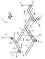
- FIG. 1 shows a three-dimensional, schematic view of a hydraulic circuit
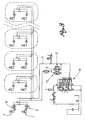
- figure 3 represents a detailed diagram of a hydraulic system comprising the circuit in figure 1.
- a hydraulic circuit is globally indicated with reference numeral 1, according to the present invention, according to a preferred embodiment.
- Said circuit comprises at least one actuator 2 for lifting a bed and/or footboard.
- Said actuator is preferably a single action type actuator, in other words it is suitable to influence the bed only for lifting, whereas the lowering of said bed is achieved by gravity.
- said actuator is a double action type actuator, in other words it is suitable to influence the footboard so it can be both lifted and lowered.
- the hydraulic circuit 1 comprises a main line 4 that is operatively connected to said actuators.
- Said main line 4 is preferably connected in parallel to said actuators 2.
- said main line 4 comprises branching out stretches 4a, which branch out from said main line 4.
- said hydraulic circuit 1 comprises a pilot line 6, which is operatively connected to said actuators 2 suitable to transmit a pilot signal in the form of work fluid pressure.
- said pilot line 6 is connected in parallel to said actuators 2.
- said pilot line 6 comprises branching out stretches 6a, which branch out from said pilot line 6.
- the hydraulic circuit 1 also comprises at least one lock valve 8. Said circuit preferably comprises a lock valve 8 for each actuator 2.
- Said lock valve is, for example, a three-way valve, in particular with two inputs and one output.
- said lock valve 8 is connected in input to a branching out stretch 4a of the main line 4 of the circuit, to a branching out stretch 6a of the pilot line 6, and, in output, to a connecting strip 10 to the respective actuator 2.
- the lock valve 8 is realised so that it constitutes a unidirectional valve, sometimes called a "no return" valve, from the main line 4 to the connecting strip 10 to the actuator 2.
- the lock valve 8 can be crossed by the work fluid from the main line 4 to the connecting strip 10, feeding the actuator. In these conditions, on the contrary, the lock valve cannot be crossed by the work fluid from the connecting strip 10 to the main line 4, preventing the actuator from withdrawing.
- the lock valve 8 When there is a pilot signal along the pilot line 6, the lock valve 8 is piloted on opening, in other words it allows the work fluid to pass from the connecting strip 10 to the main line 4.
- said lock valve is gauged at a first level of pressure, for example between 25 and 45 bars inclusive, preferably between 30 and 40 bars.
- said hydraulic circuit preferably comprises a pressure switch.
- said hydraulic circuit preferably comprises a pressure test connector. Said pressure switch and/or said pressure test connector are preferably operatively connected to said pilot line 6, upstream of said branching out stretches 6a.
- the hydraulic circuit 1 comprises a main lock valve 12 and a distributor 16 upstream of said main lock valve.
- Said main lock valve 12 is preferably a four-way valve with two inputs and two outputs.
- a first output is drained.
- a second output is connected to the main line 4.
- a first input is connected to the pilot line 6.
- a second input is connected to a connecting strip 14 with the distributor 16.
- Said main lock valve 12 comprises two normally closed two-way valves, in other words to prevent the work fluid from passing unless a preset command signal is given.
- said two-way valves are gauged at a second level of pressure, which is generally much higher than the first level of pressure at which the lock valves 8 are gauged.
- Said second level of pressure is preferably equal to three or four times the first level of pressure.
- the first two-way valve is connected to the connecting strip 14 and to the main line 4.
- the second two-way valve is connected to the pilot line 6 and is drained.
- the first two-way valve is influenced on opening by the pilot signal and by the work fluid in the main line 4.
- the second two-way valve is influenced on opening by the level of pressure of the connecting strip 14.
- the distributor 16 is connected in input to a power line 18 that is connected to a device for putting the fluid under pressure, for example an electro-pump, which is also drained.
- a device for putting the fluid under pressure for example an electro-pump, which is also drained.
- said pilot line 6 pilots the lock valves 8, so that said valves can be crossed by the work fluid from the connecting strip 10 to the branching out stretch 4a of the main line 4.
- the actuators are authorised to lower, although this does not take place until the first two-way valve of the main lock valve 12 is open.
- the first two-way valve of the main lock valve 12 is influenced on opening by the level of pressure in the main line 4.
- the second level of pressure is much higher than the first level of pressure that makes the lock vales 8 open, so the main lock valve 12 only opens when the second level of pressure is reached in the main line by means of the load weighing on the bed.
- the hydraulic circuit allows correct lowering of the bed or floorboard that are influenced by the actuators.
- the circuit foresees a first valve to authorise the lowering and a second valve which effectively permits the lowering.
- This second valve is brought into an open position only when there is a determined load weighing on the bed.
- This circuit is particularly suitable for use with commercial vehicles, trailers, semi-trailers and lorries, which often present a considerable difference in the conditions of the load weighing on each actuator, as they have large beds for lifting or lowering.
- the above-described circuit allows the bed or footboard to be held at a determined height, even when there is a leakage of work fluid.
- the above-described circuit allows the authorisation to lower the actuators, which is piloted by the pilot signal of the pilot line, and the actual lowering, which is commanded by the load conditions weighing on the bed or footboard.
- the lowering takes place when it is commanded and authorised. If there is also authorisation for all of the lock valves, but not a lowering command, in other words the main lock valve stays closed, the lowering does not take place.
- a bed or footboard for example, act in conjunction with a number of actuators for their lifting and lowering, and said hydraulic circuit presents a number of lock valves inferior to the number of actuators.
- not all of the actuators are fitted with a lock valve.
Landscapes
- Engineering & Computer Science (AREA)
- Transportation (AREA)
- Mechanical Engineering (AREA)
- Health & Medical Sciences (AREA)
- Public Health (AREA)
- Fluid-Pressure Circuits (AREA)
- Forklifts And Lifting Vehicles (AREA)
Claims (14)
- Hydraulikkreis (1), geeignet zur Wirkung in Verbindung mit einer Ladefläche und/oder einer Plattform, die angehoben und gesenkt werden soll, wobei der Kreis an eine Vorrichtung zum Unter-Druck-Setzen eines Arbeitsfluids anbringbar ist, wobei der Kreis umfasst:- mindestens einen Betätiger bzw. Stellglied (2), der betriebsmäßig an die Ladefläche oder Plattform anschließbar ist;- eine Hauptleitung (4) für das Zuführen des Arbeitsfluids zu dem Betäti-ger (2);- eine Pilot- bzw. Steuerleitung (6), getrennt von der Hauptleitung (4), die geeignet ist, ein Pilot- bzw. Steuersignal zu übertragen;- mindestens ein Sperrventil (8), eingesetzt stromaufwärts von jedem Betätiger (2), das betriebsmäßig an die Hauptleitung und an die Pilot- bzw. Steuerleitung angeschlossen ist, wobei das Ventil unidirektional in einer Richtung zum Betätiger ist und beim bzw. nach Öffnen in die entgegen gesetzte Richtung steuerbar ist und beim bzw. nach Öffnen auf einen ersten Druckwert der Pilot- bzw. Steuerleitung (6) kalibriert bzw. einge-stellt ist;wobei der Kreis dadurch gekennzeichnet ist, dass er auch umfasst- einen Verteiler (16), der betriebsmäßig an die Hauptleitung (4) und an die Pilot- bzw. Steuerleitung (6) angeschlossen ist und an die Vorrich-tung für das Unter-Druck-Setzen des Fluids anbringbar ist; und- ein Hauptsperrventil (12), stromaufwärts von dem zumindest einen Sperrventil (8) und stromabwärts von dem Verteiler, das betriebsmäßig an den Verteiler (16), an die Pilot- bzw. Steuerleitung und an die Haupt-leitung angeschlossen ist, wobei das Hauptsperrventil (12) beim bzw. nach Öffnen auf einen zweiten Druckwert der Hauptleitung (4) kalibriert bzw. eingestellt ist, der größer als der erste Druckwert ist, wobei in der offenen Position der Rückfluss des Arbeitsfluids von der Hauptleitung zugelassen wird.
- Kreis nach Anspruch 1, wobei der zumindest eine Betätiger (2) ein einfach wirkender Betätiger ist.
- Kreis nach Anspruch 1, wobei der zumindest eine Betätiger (2) ein doppelt wirkender Betätiger ist.
- Kreis nach einem der vorangehenden Ansprüche, wobei das Hauptsperrventil (12) ein Vierwegeventil ist.
- Kreis nach einem der Ansprüche 1 bis 3, wobei das Sperrventil (8) ein Dreiwegeventil ist.
- Kreis nach einem der vorangehenden Ansprüche, wobei der Verteiler (16) ei-ne Mittelstellung bietet, in der die Pilot- bzw. Steuerleitung (6) abgelassen wird.
- Kreis nach einem der vorangehenden Ansprüche, wobei der Verteiler (16) ei-ne anhebende Position bietet, in der die Vorrichtung für das Unter-Druck-Setzen des Fluids betriebsmäßig an die Hauptleitung (4) angeschlossen ist.
- Kreis nach einem der vorangehenden Ansprüche, wobei der Verteiler eine senkende Position bietet, in der die Pilot- bzw. Steuerleitung (6) unter Druck ist.
- Hydrauliksystem, das einen Kreis (1) gemäß einem der vorangehenden Ansprüche umfasst, das zusätzlich die Vorrichtung für das Unter-Druck-Setzen des Fluids enthält.
- System nach Anspruch 9, wobei die Vorrichtung für das Unter-Druck-Setzen des Fluids eine elektrische Pumpe ist.
- Anhänger, Sattelschleppzug oder Fahrzeug für das Transportieren von Waren, mit einer Ladefläche oder einer Plattform, die angehoben und gesenkt werden soll, und einem Kreis nach einem der vorangehenden Ansprüche von 1 bis 8.
- Anhänger, Sattelschleppzug oder Fahrzeug nach Anspruch 11 mit zusätzlichen Betätigern, die nicht in Verbindung mit Sperrventilen (8) fungieren.
- Hydraulikkreis (1), geeignet zur Wirkung in Verbindung mit einer Ladefläche und/oder einer Plattform, die angehoben und gesenkt werden soll, wobei der Kreis umfasst:- mindestens einen Betätiger bzw. Stellglied (2), der betriebsmäßig an die Ladefläche oder Plattform anschließbar ist;- eine Hauptleitung (4) für das Zuführen des Arbeitsfluids zu dem Betäti-ger (2);- eine Pilot- bzw. Steuerleitung (6), getrennt von der Hauptleitung (4), die geeignet ist, ein Pilot- bzw. Steuersignal zu übertragen;- mindestens ein Sperrventil (8), eingesetzt stromaufwärts von jedem Betätiger (2), das betriebsmäßig an die Hauptleitung angeschlossen ist, wobei das Ventil unidirektional in einer Richtung zum Betätiger ist und beim bzw. nach Öffnen in die entgegen gesetzte Richtung durch das Pi-lot- bzw. Steuersignal steuerbar ist;wobei der Kreis dadurch gekennzeichnet ist, dass er auch umfasst
ein Hauptsperrventil (12), das betriebsmäßig an die Hauptleitung (4) angeschlossen ist, wobei das Hauptsperrventil (12) beim bzw. nach Öffnen durch die Belastungszustände, die auf der Ladefläche lasten, steuerbar ist, um den Rückfluss des Arbeitsfluids von der Hauptleitung zu erlauben. - Hydraulikkreis (1), geeignet zur Wirkung in Verbindung mit einer Ladefläche und/oder einer Plattform zum Anheben und Senken, wobei der Kreis umfasst:- mindestens einen Betätiger bzw. Stellglied (2), der betriebsmäßig an die Ladefläche oder Plattform anschließbar ist;- eine Hauptleitung (4) für das Zuführen des Arbeitsfluids zu dem Betäti-ger (2);- eine Pilot- bzw. Steuerleitung (6), getrennt von der Hauptleitung (4), die geeignet ist, ein Pilot- bzw. Steuersignal zu übertragen;- mindestens ein Sperrventil (8), eingesetzt stromaufwärts von jedem Betätiger (2), das betriebsmäßig an die Hauptleitung angeschlossen ist,wobei der Kreis dadurch gekennzeichnet ist, dass er auch umfasst- ein Hauptsperrventil (12), stromaufwärts von dem zumindest einen Sperrventil (8), das betriebsmäßig an die Hauptleitung (4) angeschlos-sen ist,wobei, um die Ladefläche zu senken, das Pilot- bzw. Steuersig-nal das mindestens eine Sperrventil (8) autorisiert und die Last, die auf der Ladefläche lastet, das Hauptsperrventil (12) für den Rückfluss des Arbeitsfluids von der Hauptleitung (4) öffnet.
Applications Claiming Priority (1)
| Application Number | Priority Date | Filing Date | Title |
|---|---|---|---|
| IT2004000559 | 2004-10-08 |
Publications (2)
| Publication Number | Publication Date |
|---|---|
| EP1645463A1 EP1645463A1 (de) | 2006-04-12 |
| EP1645463B1 true EP1645463B1 (de) | 2007-12-19 |
Family
ID=35033522
Family Applications (1)
| Application Number | Title | Priority Date | Filing Date |
|---|---|---|---|
| EP04425797A Expired - Lifetime EP1645463B1 (de) | 2004-10-08 | 2004-10-25 | Hydraulikkreis zum Heben und Senken von Ladeflächen in Lastfahrzeugen |
Country Status (3)
| Country | Link |
|---|---|
| EP (1) | EP1645463B1 (de) |
| AT (1) | ATE381463T1 (de) |
| DE (1) | DE602004010813D1 (de) |
Families Citing this family (1)
| Publication number | Priority date | Publication date | Assignee | Title |
|---|---|---|---|---|
| GB2554335B (en) * | 2016-05-20 | 2019-10-09 | Parkhouse Country Estates Ltd | A hydraulic vehicular roof assembly |
Family Cites Families (3)
| Publication number | Priority date | Publication date | Assignee | Title |
|---|---|---|---|---|
| US5110251A (en) * | 1989-01-17 | 1992-05-05 | Gray Ralph E | Hydraulic platform lift for truck trailers |
| US5791860A (en) * | 1997-01-27 | 1998-08-11 | Holland Equipment Limited | Hydraulic platform lift for a truck tailgate |
| DE19960302A1 (de) * | 1999-12-14 | 2001-06-21 | Meiller Fahrzeuge | Steuerventilanordnung für einen hydraulischen Zylinder |
-
2004
- 2004-10-25 EP EP04425797A patent/EP1645463B1/de not_active Expired - Lifetime
- 2004-10-25 DE DE602004010813T patent/DE602004010813D1/de not_active Expired - Lifetime
- 2004-10-25 AT AT04425797T patent/ATE381463T1/de not_active IP Right Cessation
Also Published As
| Publication number | Publication date |
|---|---|
| ATE381463T1 (de) | 2008-01-15 |
| DE602004010813D1 (de) | 2008-01-31 |
| EP1645463A1 (de) | 2006-04-12 |
Similar Documents
| Publication | Publication Date | Title |
|---|---|---|
| DE10333610B4 (de) | Druckluftaufbereitungseinrichtung für Kraftfahrzeug-Druckluftanlagen | |
| EP0883538B1 (de) | Anhängersteuerventil für eine druckluftbremsanlage für kraftfahrzeuge | |
| EP1369598B1 (de) | Elektrohydraulische Hubsteuervorrichtung für Flurförderfahrzeuge | |
| EP2384943B1 (de) | Ventileinrichtung, elektrisch betätigbares Feststellbremssystem und Verfahren zum Steuern eines elektrisch betätigbaren Feststellbremssystems | |
| EP2964963B1 (de) | Pilotdruckregelungssystem | |
| DE102016106793B4 (de) | Hydraulische Lenkung | |
| DE102011051505B4 (de) | Niveauregelventileinheit mit integriertem Verteiler | |
| EP2338753A1 (de) | Elektrisch betätigbares Feststellbremssystem und Verfahren zum Steuern eines elektrisch betätigbaren Feststellbremssystems | |
| EP2540538B1 (de) | Luftfederungsanlage | |
| EP1645463B1 (de) | Hydraulikkreis zum Heben und Senken von Ladeflächen in Lastfahrzeugen | |
| DE102015115082B4 (de) | Ventileinheit für pneumatische Anwendungen sowie Luftfederungsanlage | |
| EP2338754B1 (de) | Elektrisch betätigbares Feststellbremssystem und Verfahren zum Steuern eines elektrisch betätigbaren Feststellbremssystems | |
| DE2533673C2 (de) | Hydraulisches Steuersystem | |
| EP2016818B1 (de) | Hubwerk und Verfahren zum Ansteuern eines derartigen Hubwerks | |
| DE102012107971A1 (de) | Hydraulisches Antriebssystem einer mobilen Arbeitsmaschine | |
| EP2466154B1 (de) | Elektrohydraulische Steuervorrichtung | |
| US7152401B2 (en) | Hydraulic steering arrangement | |
| EP2016817B1 (de) | Verfahren zum Ansteuern eines Hubwerks und Hubwerk | |
| US20200340499A1 (en) | Control device | |
| EP2657178B9 (de) | Hydraulikanlage einer mobilen Arbeitsmaschine | |
| EP2251299A1 (de) | Druckenergiespeicher | |
| EP3037678B1 (de) | Hubmodul | |
| JPH075272B2 (ja) | サイドシフトクランプ装置 | |
| EP2384944B1 (de) | Verfahren zum Steuern eines elektrisch betätigbaren Feststellbremssystems | |
| EP1754682B1 (de) | Elektrohydraulische Vorrichtung |
Legal Events
| Date | Code | Title | Description |
|---|---|---|---|
| PUAI | Public reference made under article 153(3) epc to a published international application that has entered the european phase |
Free format text: ORIGINAL CODE: 0009012 |
|
| AK | Designated contracting states |
Kind code of ref document: A1 Designated state(s): AT BE BG CH CY CZ DE DK EE ES FI FR GB GR HU IE IT LI LU MC NL PL PT RO SE SI SK TR |
|
| AX | Request for extension of the european patent |
Extension state: AL HR LT LV MK |
|
| 17P | Request for examination filed |
Effective date: 20060613 |
|
| 17Q | First examination report despatched |
Effective date: 20060720 |
|
| AKX | Designation fees paid |
Designated state(s): AT BE BG CH CY CZ DE DK EE ES FI FR GB GR HU IE IT LI LU MC NL PL PT RO SE SI SK TR |
|
| GRAP | Despatch of communication of intention to grant a patent |
Free format text: ORIGINAL CODE: EPIDOSNIGR1 |
|
| GRAS | Grant fee paid |
Free format text: ORIGINAL CODE: EPIDOSNIGR3 |
|
| GRAA | (expected) grant |
Free format text: ORIGINAL CODE: 0009210 |
|
| AK | Designated contracting states |
Kind code of ref document: B1 Designated state(s): AT BE BG CH CY CZ DE DK EE ES FI FR GB GR HU IE IT LI LU MC NL PL PT RO SE SI SK TR |
|
| REG | Reference to a national code |
Ref country code: GB Ref legal event code: FG4D |
|
| REG | Reference to a national code |
Ref country code: IE Ref legal event code: FG4D |
|
| REG | Reference to a national code |
Ref country code: CH Ref legal event code: EP |
|
| REF | Corresponds to: |
Ref document number: 602004010813 Country of ref document: DE Date of ref document: 20080131 Kind code of ref document: P |
|
| PG25 | Lapsed in a contracting state [announced via postgrant information from national office to epo] |
Ref country code: LI Free format text: LAPSE BECAUSE OF FAILURE TO SUBMIT A TRANSLATION OF THE DESCRIPTION OR TO PAY THE FEE WITHIN THE PRESCRIBED TIME-LIMIT Effective date: 20071219 Ref country code: CH Free format text: LAPSE BECAUSE OF FAILURE TO SUBMIT A TRANSLATION OF THE DESCRIPTION OR TO PAY THE FEE WITHIN THE PRESCRIBED TIME-LIMIT Effective date: 20071219 Ref country code: SE Free format text: LAPSE BECAUSE OF FAILURE TO SUBMIT A TRANSLATION OF THE DESCRIPTION OR TO PAY THE FEE WITHIN THE PRESCRIBED TIME-LIMIT Effective date: 20080319 |
|
| PG25 | Lapsed in a contracting state [announced via postgrant information from national office to epo] |
Ref country code: SI Free format text: LAPSE BECAUSE OF FAILURE TO SUBMIT A TRANSLATION OF THE DESCRIPTION OR TO PAY THE FEE WITHIN THE PRESCRIBED TIME-LIMIT Effective date: 20071219 Ref country code: PL Free format text: LAPSE BECAUSE OF FAILURE TO SUBMIT A TRANSLATION OF THE DESCRIPTION OR TO PAY THE FEE WITHIN THE PRESCRIBED TIME-LIMIT Effective date: 20071219 Ref country code: NL Free format text: LAPSE BECAUSE OF FAILURE TO SUBMIT A TRANSLATION OF THE DESCRIPTION OR TO PAY THE FEE WITHIN THE PRESCRIBED TIME-LIMIT Effective date: 20071219 Ref country code: FI Free format text: LAPSE BECAUSE OF FAILURE TO SUBMIT A TRANSLATION OF THE DESCRIPTION OR TO PAY THE FEE WITHIN THE PRESCRIBED TIME-LIMIT Effective date: 20071219 |
|
| NLV1 | Nl: lapsed or annulled due to failure to fulfill the requirements of art. 29p and 29m of the patents act | ||
| REG | Reference to a national code |
Ref country code: CH Ref legal event code: PL |
|
| PG25 | Lapsed in a contracting state [announced via postgrant information from national office to epo] |
Ref country code: AT Free format text: LAPSE BECAUSE OF FAILURE TO SUBMIT A TRANSLATION OF THE DESCRIPTION OR TO PAY THE FEE WITHIN THE PRESCRIBED TIME-LIMIT Effective date: 20071219 |
|
| PG25 | Lapsed in a contracting state [announced via postgrant information from national office to epo] |
Ref country code: ES Free format text: LAPSE BECAUSE OF FAILURE TO SUBMIT A TRANSLATION OF THE DESCRIPTION OR TO PAY THE FEE WITHIN THE PRESCRIBED TIME-LIMIT Effective date: 20080330 Ref country code: CZ Free format text: LAPSE BECAUSE OF FAILURE TO SUBMIT A TRANSLATION OF THE DESCRIPTION OR TO PAY THE FEE WITHIN THE PRESCRIBED TIME-LIMIT Effective date: 20071219 |
|
| PG25 | Lapsed in a contracting state [announced via postgrant information from national office to epo] |
Ref country code: BE Free format text: LAPSE BECAUSE OF FAILURE TO SUBMIT A TRANSLATION OF THE DESCRIPTION OR TO PAY THE FEE WITHIN THE PRESCRIBED TIME-LIMIT Effective date: 20071219 Ref country code: SK Free format text: LAPSE BECAUSE OF FAILURE TO SUBMIT A TRANSLATION OF THE DESCRIPTION OR TO PAY THE FEE WITHIN THE PRESCRIBED TIME-LIMIT Effective date: 20071219 Ref country code: RO Free format text: LAPSE BECAUSE OF FAILURE TO SUBMIT A TRANSLATION OF THE DESCRIPTION OR TO PAY THE FEE WITHIN THE PRESCRIBED TIME-LIMIT Effective date: 20071219 |
|
| PG25 | Lapsed in a contracting state [announced via postgrant information from national office to epo] |
Ref country code: PT Free format text: LAPSE BECAUSE OF FAILURE TO SUBMIT A TRANSLATION OF THE DESCRIPTION OR TO PAY THE FEE WITHIN THE PRESCRIBED TIME-LIMIT Effective date: 20080519 |
|
| EN | Fr: translation not filed | ||
| PLBE | No opposition filed within time limit |
Free format text: ORIGINAL CODE: 0009261 |
|
| STAA | Information on the status of an ep patent application or granted ep patent |
Free format text: STATUS: NO OPPOSITION FILED WITHIN TIME LIMIT |
|
| PG25 | Lapsed in a contracting state [announced via postgrant information from national office to epo] |
Ref country code: DK Free format text: LAPSE BECAUSE OF FAILURE TO SUBMIT A TRANSLATION OF THE DESCRIPTION OR TO PAY THE FEE WITHIN THE PRESCRIBED TIME-LIMIT Effective date: 20071219 Ref country code: DE Free format text: LAPSE BECAUSE OF FAILURE TO SUBMIT A TRANSLATION OF THE DESCRIPTION OR TO PAY THE FEE WITHIN THE PRESCRIBED TIME-LIMIT Effective date: 20080320 |
|
| 26N | No opposition filed |
Effective date: 20080922 |
|
| PGFP | Annual fee paid to national office [announced via postgrant information from national office to epo] |
Ref country code: IT Payment date: 20080724 Year of fee payment: 5 |
|
| PG25 | Lapsed in a contracting state [announced via postgrant information from national office to epo] |
Ref country code: GR Free format text: LAPSE BECAUSE OF FAILURE TO SUBMIT A TRANSLATION OF THE DESCRIPTION OR TO PAY THE FEE WITHIN THE PRESCRIBED TIME-LIMIT Effective date: 20080320 |
|
| PG25 | Lapsed in a contracting state [announced via postgrant information from national office to epo] |
Ref country code: FR Free format text: LAPSE BECAUSE OF FAILURE TO SUBMIT A TRANSLATION OF THE DESCRIPTION OR TO PAY THE FEE WITHIN THE PRESCRIBED TIME-LIMIT Effective date: 20081010 Ref country code: BG Free format text: LAPSE BECAUSE OF FAILURE TO SUBMIT A TRANSLATION OF THE DESCRIPTION OR TO PAY THE FEE WITHIN THE PRESCRIBED TIME-LIMIT Effective date: 20080319 Ref country code: EE Free format text: LAPSE BECAUSE OF FAILURE TO SUBMIT A TRANSLATION OF THE DESCRIPTION OR TO PAY THE FEE WITHIN THE PRESCRIBED TIME-LIMIT Effective date: 20071219 |
|
| PG25 | Lapsed in a contracting state [announced via postgrant information from national office to epo] |
Ref country code: MC Free format text: LAPSE BECAUSE OF NON-PAYMENT OF DUE FEES Effective date: 20081031 |
|
| GBPC | Gb: european patent ceased through non-payment of renewal fee |
Effective date: 20081025 |
|
| PG25 | Lapsed in a contracting state [announced via postgrant information from national office to epo] |
Ref country code: CY Free format text: LAPSE BECAUSE OF FAILURE TO SUBMIT A TRANSLATION OF THE DESCRIPTION OR TO PAY THE FEE WITHIN THE PRESCRIBED TIME-LIMIT Effective date: 20071219 |
|
| PG25 | Lapsed in a contracting state [announced via postgrant information from national office to epo] |
Ref country code: IE Free format text: LAPSE BECAUSE OF NON-PAYMENT OF DUE FEES Effective date: 20081027 |
|
| PG25 | Lapsed in a contracting state [announced via postgrant information from national office to epo] |
Ref country code: GB Free format text: LAPSE BECAUSE OF NON-PAYMENT OF DUE FEES Effective date: 20081025 |
|
| PG25 | Lapsed in a contracting state [announced via postgrant information from national office to epo] |
Ref country code: LU Free format text: LAPSE BECAUSE OF NON-PAYMENT OF DUE FEES Effective date: 20081025 Ref country code: HU Free format text: LAPSE BECAUSE OF FAILURE TO SUBMIT A TRANSLATION OF THE DESCRIPTION OR TO PAY THE FEE WITHIN THE PRESCRIBED TIME-LIMIT Effective date: 20080620 |
|
| PG25 | Lapsed in a contracting state [announced via postgrant information from national office to epo] |
Ref country code: TR Free format text: LAPSE BECAUSE OF FAILURE TO SUBMIT A TRANSLATION OF THE DESCRIPTION OR TO PAY THE FEE WITHIN THE PRESCRIBED TIME-LIMIT Effective date: 20071219 |
|
| PG25 | Lapsed in a contracting state [announced via postgrant information from national office to epo] |
Ref country code: IT Free format text: LAPSE BECAUSE OF NON-PAYMENT OF DUE FEES Effective date: 20091025 |