EP1643733A1 - Procédé pour annuler une fonction temporisée dans un radiotéléphone - Google Patents
Procédé pour annuler une fonction temporisée dans un radiotéléphone Download PDFInfo
- Publication number
- EP1643733A1 EP1643733A1 EP05023796A EP05023796A EP1643733A1 EP 1643733 A1 EP1643733 A1 EP 1643733A1 EP 05023796 A EP05023796 A EP 05023796A EP 05023796 A EP05023796 A EP 05023796A EP 1643733 A1 EP1643733 A1 EP 1643733A1
- Authority
- EP
- European Patent Office
- Prior art keywords
- sleeve
- keys
- handset
- extending portion
- call
- Prior art date
- Legal status (The legal status is an assumption and is not a legal conclusion. Google has not performed a legal analysis and makes no representation as to the accuracy of the status listed.)
- Granted
Links
Images


Classifications
-
- H—ELECTRICITY
- H04—ELECTRIC COMMUNICATION TECHNIQUE
- H04M—TELEPHONIC COMMUNICATION
- H04M1/00—Substation equipment, e.g. for use by subscribers
- H04M1/02—Constructional features of telephone sets
- H04M1/0202—Portable telephone sets, e.g. cordless phones, mobile phones or bar type handsets
- H04M1/0206—Portable telephones comprising a plurality of mechanically joined movable body parts, e.g. hinged housings
- H04M1/0208—Portable telephones comprising a plurality of mechanically joined movable body parts, e.g. hinged housings characterized by the relative motions of the body parts
- H04M1/0235—Slidable or telescopic telephones, i.e. with a relative translation movement of the body parts; Telephones using a combination of translation and other relative motions of the body parts
- H04M1/0237—Sliding mechanism with one degree of freedom
-
- H—ELECTRICITY
- H04—ELECTRIC COMMUNICATION TECHNIQUE
- H04M—TELEPHONIC COMMUNICATION
- H04M1/00—Substation equipment, e.g. for use by subscribers
- H04M1/02—Constructional features of telephone sets
- H04M1/0202—Portable telephone sets, e.g. cordless phones, mobile phones or bar type handsets
- H04M1/0206—Portable telephones comprising a plurality of mechanically joined movable body parts, e.g. hinged housings
- H04M1/0241—Portable telephones comprising a plurality of mechanically joined movable body parts, e.g. hinged housings using relative motion of the body parts to change the operational status of the telephone set, e.g. switching on/off, answering incoming call
- H04M1/0245—Portable telephones comprising a plurality of mechanically joined movable body parts, e.g. hinged housings using relative motion of the body parts to change the operational status of the telephone set, e.g. switching on/off, answering incoming call using open/close detection
-
- H—ELECTRICITY
- H04—ELECTRIC COMMUNICATION TECHNIQUE
- H04M—TELEPHONIC COMMUNICATION
- H04M1/00—Substation equipment, e.g. for use by subscribers
- H04M1/72—Mobile telephones; Cordless telephones, i.e. devices for establishing wireless links to base stations without route selection
- H04M1/724—User interfaces specially adapted for cordless or mobile telephones
-
- H—ELECTRICITY
- H04—ELECTRIC COMMUNICATION TECHNIQUE
- H04M—TELEPHONIC COMMUNICATION
- H04M1/00—Substation equipment, e.g. for use by subscribers
- H04M1/02—Constructional features of telephone sets
- H04M1/0202—Portable telephone sets, e.g. cordless phones, mobile phones or bar type handsets
- H04M1/0206—Portable telephones comprising a plurality of mechanically joined movable body parts, e.g. hinged housings
- H04M1/0208—Portable telephones comprising a plurality of mechanically joined movable body parts, e.g. hinged housings characterized by the relative motions of the body parts
- H04M1/0235—Slidable or telescopic telephones, i.e. with a relative translation movement of the body parts; Telephones using a combination of translation and other relative motions of the body parts
Definitions
- the invention relates to a radio telephone sometimes termed a radio handset and more particularly to a compact radio handset.
- Such phones do, however, tend to be relatively flimsy and prone to damage especially when the flap is open since it is then extremely prone to accidental knocks or other rough treatment.
- the hinged flap also presents the difficulty of implementing a reliable conductive path from the microphone to the main body of the telephone across the hinge.
- the compact telephone or handset described in this patent comprises a main body and a cover portion arranged for longitudinal sliding movement relative to the main body. In the retracted position the phone is compact and easy to store, In the extended position the phone is dimensioned such that it comfortably bridges the gap between the user's ear and mouth.
- the design is both compact and relatively robust.
- connection enabling the call answer/send mode is only made when the cover portion is in its fully extended position.
- the handset can only be used for making or answering a call when the cover is in its fully extended position.
- the action of closing the sleeve terminates a call, regardless of whether it is incoming or outgoing.
- US 5,175,759 describes a portable radio telephone with a moveable flip element for covering a keypad.
- the flip is used as a switch, the function of which changes depending on the state of the phone.
- When the flip is opened it answers an incoming call and if there is no incoming call deactivates a mute function.
- When the flip is closed and left during a call the telephone goes on hook and the call is terminated.
- the flip is closed and then opened during a call the action depends upon the state of the phone. It may for example disable voice recognition or switch to hands free mode.
- GB 2253967 describes a portable radio telephone that has a voice operated switch which causes the telephone to go off-hook if the voice operated switch is actuated during an incoming call.
- the user may be required to confirm the off-hook condition by pressing a key on the telephone keypad. Failure to confirm the off-hook condition will terminate the telephone call.
- the method may be performed by a radio handset comprising a housing having user input means and a processor operable to perform a predetermined function in response to user input of a predefined actuation signal, wherein the processor is operable to delay performance of the predetermined function for a period during which user generation of a predefined cancellation signal cancels performance of the predetermined function.
- the user By providing a period of delay between the initiation and performance of a function, the user is provided with the opportunity to cancel performance of the function by provision of a predefined cancellation signal.
- the present invention allows for this opportunity to be realised.
- the housing provides the user input means and comprises a key pad including a plurality of keys mounted on a main body and an extending portion mounted for movement between a first position in which a group of the plurality of keys are concealed and a second position in which the group of the plurality of keys are exposed, and wherein the processor is operable to perform the predetermined function in response to movement of the extending portion.
- the predetermined function preferably comprises placing the handset in the off-hook condition for receiving an incoming call.
- One desirable option for a radio telephone is that moving the extending portion from the closed position serves to answer an incoming call. As the user will likely wish to extend the handset in order to participate in a conversation. By enabling this movement to provide the additional function of answering the call allows the user to avoid performing an additional function to answer the call once the handset has been made physically ready for communication with another party.
- extending the phone will be an automatic or reflex response, and if this action automatically answers a call the user may answer a call on reflection he/she would rather have left unanswered.
- Embodiments of the present invention provide the means by which an additional operation performed by the user in a predetermined delay period, can cancel the function initiated by movement of the extending portion.
- the user If in the period of delay, the user reads calling line identification information on the screen, the user can cancel the receipt of an incoming call from an unwanted or inconvenient caller.
- actuation of one of the plurality of keys or movement of the extending portion to the first position cancels performance of the predetermined function.
- a simple actuation of a key, or movement of the extending portion can accordingly cancel initiation of the off-hook condition for answering a call.
- the extending portion is mounted for longitudinal slidable movement between the first and second positions and the processor means is operable to perform the predetermined functions corresponding to sequences of actuations of exposed ones of the plurality of keys for a range of positions of the extending portion. This enables exposed keys to be utilised for cancelling the function.
- the radio handset may comprise a housing having a key pad including a plurality of keys mounted on a main body and an extending portion mounted for movement between a first position in which a group of the plurality of keys are concealed and a second position in which the group of the plurality of keys are exposed, and a processor operable to perform a predetermined function in response to movement of the extending portion, wherein the processor is operable to delay performance of the predetermined function for a period during which generation of a predefined cancellation signal cancels performance of the predetermined function.
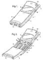
- a radio handset in accordance with an embodiment of this invention shown in Figures 1 to 10 comprises a housing 1 having a main body 2 enclosing substantially the whole of the electronic circuitry of the radio telephone and a sleeve portion 3 slidably mounted on the main body 2.
- the handset has an antenna 5, a transceiver 6 and processing means 7 programmed with an algorithm which is operative to select a communication channel with a base station ( Figure 2).
- Information is displayed on a Liquid Crystal Display (LCD) 8.
- LCD Liquid Crystal Display
- SEND call start
- END END
- the display panel, LCD 8 is located on the housing above the two groups of keys. Above the display is located a series of holes 12 behind which is an earphone or speaker 13 for transmitting speech or other sounds to the user of the radio handset.
- the sleeve has a series of holes 14 at its lower end behind which is mounted a microphone 15 ( Figure 2).
- the sleeve portion 3 is arranged to slide relative to the main body between a closed position illustrated in Figure 1 and a fully open position illustrated in Figure 3.
- the main body of the housing is curved and the sleeve-like portion provides a curvature sufficient for the ear 13 and mouth 15 pieces to be positioned respectively adjacent the ear and mouth of the user.
- the material chosen for the slide of this particular embodiment of the invention is a polycarbonate with added teflon to provide a satisfying sliding feel when in use.
- both groups of keys 10,11 are concealed ( Figure 1); the only control keys available for use being a volume control key 16 positioned on the side of the handset and a power control key 50.
- Figure 3 In the fully open position ( Figure 3) both groups of keys 10,11 are revealed allowing both numerical and control buttons to be selected.
- Figure 4 A third sleeve position is illustrated in Figure 4 in which the sleeve is partially open showing only the second group of keys 11. In this position the control keys can still be selected but the numeric keys cannot as they are concealed. Calls can be made using the control keys ie calls from memory, and calls can be answered. In this embodiment it is the physical concealment of the keys that prevents them from being used.
- the microprocessor 7 is functional at all times, when the numerical keys 10 of the first group are concealed they cannot physically be actuated to make a telephone call.
- the volume key 16 When the sleeve is fully closed, the only key that can be actuated to perform functions other than a power key 50 is the volume key 16, a third key group, positioned on the side of the phone and revealed for all positions of the sleeve.
- the handset is programmed to allow actuation of the volume key 16 forming a third group of keys, when the sleeve 3 is in the closed position to answer calls. Additional keys could be exposed when the sleeve is closed.
- the sleeve portion 3 is attached to the main body 2 for sliding movement relative thereto.
- a groove 20 is provided on each side of the main body ( Figures 3,4,5) running substantially along its length.
- Runners 21 positioned, one on each side of the underside of the sleeve portion ( Figure 9), are held in the grooves to allow the sleeve portion 3 to slide relative to the main body 1 whilst being captured thereby.
- the arrangement of the groups of keys is such that in particular positions the sleeve provides access to the respective groups. It is desirable, therefore, that there is a preference for the sleeve to be located in positions revealing either neither the first nor the second group of keys (closed) (Figure 1), the second group of keys alone (intermediate) ( Figure 4) or both the first and second groups of keys (fully extended) (Figure 3).
- the third group of keys ie the volume control button 16 in this embodiment is revealed at all times.
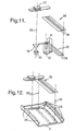
- the main body of the handset is provided with a pair of members 22 ( Figures 5,10) located within the main body that protrude one into each of the grooves 20 located on the main body 2 of the handset.
- the members 22 are spring loaded to allow the sleeve portion to move from the preferred positions when desired,
- the member 22 is resilient and mounted in a holder 24 inside the main body 2 with a detent 23 that protrudes through an aperture 25 in the groove 20.
- the detent 23 is depressed so that it no longer protrudes into the grooves 20 by one of the runners 21 of the sleeve portion 3.
- the runners are provided with recesses 26 ( Figure 9), when a recess 26 coincides with a detent 23, the sleeve 3 is held in position.
- the recesses 26 are provided so that the sleeve portion is 'caught' in the closed, intermediate and the fully open positions.
- Two of the recesses 26 in the runners 21, those corresponding to the closed and intermediate positions have cammed edges so that when extra force is provided to slide the sleeve from the first two sleeve positions, the detent 23 is depressed below the surface of the bottom of the groove 20 for disengagement from the recess 16 allowing the sleeve portion 3 to continue to slide in the chosen direction.
- the recess corresponding to the intermediate position will have cammed leading and trailing edges to allow movement in either direction.
- the recess corresponding to the closed position may only have a cammed leading edge to allow for ease in opening.
- an in-mould plastic pin 27 ( Figure 9) is provided on each side of the sleeve portion 3 of the handset. Each of these abuts complementary surfaces located on the main body 2 of the handset to substantially prevent withdrawal of the sleeve portion 3,
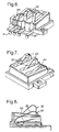
- the microphone 15 is mounted on a small flexible pcb 30 along with a filter 31 and a foam plastics member 32 that acts as an acoustic dampener together with microphone holder 33 to improve the acoustic properties of the microphone 15.
- the flexible pcb 30 also includes two conducting tracks 34 for maintaining contact between the microphone 15 and the electronics of the handset located within the housing of the main body.
- the flexible pcb 30 is mounted to the underside of the bare plastic sleeve itself suitably by laminating a polycarbonate foil 35 with apertures 36 coinciding with tracks 34 to it and then welding that part to the underside of the sleeve portion to the slide cover by ultrasonic welding.
- a microphone housing 37 surrounding the microphone 15 in the microphone holder 33 is then fitted.
- the resulting assembly 38 is attached to the underside of the sleeve 3 with the aid of guide pins indicated by dotted lines 39.
- the two conducting slide tracks 34 extend substantially from one end of the sleeve portion to the other to allow the microphone 15 to maintain electrical contact with the electronics of the handset for all positions of the sleeve between and including the open and closed positions.
- the microphone housing 37 can also suitably be ultrasonically welded to the underside of the sleeve and encloses the microphone and its components to additionally protect from dirt or other damage.
- the microphone 15 is located behind the holes 14 at the bottom end of the slide connected to the two slide tracks
- a microphone connector 40 is mounted on the main body of the handset suitably by ultrasonic welding ( Figure 5).
- the connector is positioned so that it is in electrical contact with the main pcb in the body of the handset by contacts 41 or other mechanism. It is positioned to make contact with the two slide tracks at all positions of the sleeve to provide an electrical connection between the microphone and the main processor of the handsets.
- the connection is also maintained during movement of the sleeve portion.
- the handset can, therefore, be used to the extent that the relevant keys are exposed in all positions of the sleeve relative to the main body.
- the microphone connector can be seen in greater detail in Figures 6 to 8.
- the microphone connector 40 comprises two spring contacts 42 disposed for contact with respective ones of the two slide tracks.
- the bearing surfaces 43 of the spring clip are flattened to provide for improved contact with the slide tracks.
- the spring loading of the contacts ensures good electrical contact between the microphone and microprocessor for a range of distances between the sleeve portion and main body at the microphone connector element. This provides for a good degree of tolerance for the manufacturing process. It also allows the sleeve to be at different distances from the microphone connector for respective positions of the slide.
- the electrical connection between the microphone connector and the slide tracks is hard wearing and resistant to dirt or other damage.
- the connectors are plated with 20 microns of palladium nickel followed by 2 microns of hard gold.
- the slide tracks 34 can also be plated with hard gold, in this embodiment 5 microns, for improved life.
- the microphone connector also has a built-in microswitch 44 which is activated by a protrusion located in the underside of the sleeve portion.
- the microswitch provides a signal indicating that the sleeve portion is not in the closed position. This signal is used to allow movement of the slide from the closed position to be detectable. This enables movement of the slide to be utilised to answer an incoming call.
- the microswitch 44 has a spring loaded member 45 protruding from the main body towards the sleeve cover 3 and a contact arm 46 in alignment with the spring loaded member such that when the spring loaded member is depressed by a sufficient degree contact is made with the contact arm. On such contact a signal is sent to the microprocessor.
- a protrusion 47 on the underside of the sleeve 3 in a position corresponding to the microswitch when the sleeve is in the closed position is provided on the underside of the sleeve portion.
- the protrusion 47 has a cammed surface that progressively presses the spring loaded element into contact with the contact arm as the sleeve portion slides towards the closed position.
- the switch 44 is closed when the sleeve is in the closed position and signals from the switch can, accordingly, be used as an indication as to whether or not the sleeve is closed position.
- the position of the sleeve portion can be used as an additional indication to the microprocessor.
- a call can be answered when the sleeve is moved from the closed position, and/or a call terminated when the sleeve is closed.
- One of the operating modes of the handset is 'any key answer'. If the handset is in this mode and an incoming call is indicated, the handset can be put in the off-hook condition for receiving the call by pressing any of the exposed keys other than the power key 30 including the volume control key. The only restriction is on which keys are exposed for the user to actuate. When the sleeve portion of the handset is fully open any one of the available keys can be used to answer a call.
- the volume control key 16 and the power control key 50 When in 'any key answer mode, if the sleeve is closed, there are two exposed keys, the volume control key 16 and the power control key 50.
- the handset can be closed and powered up or closed and powered down. If the handset is powered up it is in standby, ie in condition to receive calls. If the handset receives a paging message indicating that there is an incoming call for the handset, the call can be answered in two ways, either by actuating the volume control key or by sliding the sleeve from the closed position.
- the microprocessor uses the signal from the microswitch to determine that the sleeve is in the closed position. Any signal received from the volume control key when the sleeve is closed can accordingly be utilised to receive an incoming call.
- a call When the handset is in a mode other than the any key answer mode, a call must be answered by pressing the send key or, if the sleeve is closed, by displacing the sleeve.
- a call can be terminated by pressing the end key, provided it is exposed or closing the sleeve. All other functions of the telephone are operable if the keys necessary to actuate the function are exposed for actuation by the user.
- the microphone and earpiece are connected to the microprocessor for all positions of the slide and the keys are continually polled to determine if they have been actuated.
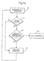
- the handset When the handset detects a paging signal 60 indicating an incoming call, the handset generates a signal alerting the user to the fact that the handset is being paged. This signal may be audible, visible or able to be detected by the user in some way eg felt. The user is then in a position to decide whether or not to answer the call.
- One option available is for the handset to display an indication of the person calling by reading calling line identification information from the paging signal. This can be displayed on the LCD.
- the handset of this embodiment of the invention is able to answer a call received when the sleeve portion is in the closed position if the slide is subsequently opened.
- the processor determines from the change in status of the signal from the microswitch 44 that the sleeve has been displaced from the closed position ie opened 61. Rather than the call being answered immediately, the processor delays placing the handset in the off-hook condition for a period T L . This period is desirably long enough to allow the user to intervene in the process but not long enough to make it likely that the paging signal will terminate before the call is answered, suitably of the order of 1 second.
- the processor 7 checks to see if the END key of the plurality of keys has been actuated or if the sleeve portion 3 has been closed with reference to the signal from the microswitch within the delay period T L 62. If either the sleeve has been closed, or the END key has been pressed or actuated, the handset is not placed in the off-hook condition to answer the call and continues to ring or otherwise indicate to the user that there is an incoming call 63 until the handset is no longer being paged. If, however, the period T L expires without either the END key being actuated or the sleeve being closed, the call is answered 64 without further input from the user.
- This delay of the order one second allows the user who has inadvertently slid the sleeve when an incoming call is indicated to override performance of this function by pressing the END key or sliding the sleeve closed again.
- Other keys could be actuated to override performance of the function indicated by movement of the sleeve from the closed position.
- the radio handset comprises a housing (1) having user input means (3,10,11,14,15,16,50) and a processor (7) operable to perform a predetermined function (63) in response to user input (61) of a predefined actuation signal, characterised in that the processor (7) is operable to delay performance of the predetermined function (63) for a period (T L ) during which user generation of a predefined cancellation signal cancels (64) performance of the predetermined function.
- the housing (1) comprises a key pad including a plurality of keys (10, 11) mounted on a main body (2) and an extending portion (3) mounted for movement between a first position in which a group (10) of the plurality of keys (10,11) are concealed and a second position in which the group (10) of the plurality of keys (10,11) are exposed, and wherein the processor (7) is operable to perform the predetermined function in response to movement of the extending portion (3).
- the predetermined function comprises placing the handset in the off-hook condition (63).
- User generation of the predefined cancellation signal comprises movement of the extending portion (3) to the first position.
- User generation of the predefined cancellation signal comprises actuation of any of the plurality of keys (10,11).
- Movement of the extending portion (3) from the first position causes the handset to be placed in the off-hook condition.
- Movement of the extending portion (3) to the first position causes the handset to be placed in the on-hook condition.
- Processor means (7) is operable to perform the predetermined functions corresponding to sequences of actuations of exposed ones of the plurality of keys (10,11 ) for a range of positions of the extending portion (3).
- the extending portion (3) is mounted for longitudinal slidable movement between the first and second positions.
- the extending portion (3) is arranged for occupying any position intermediate the first and second positions.
- the main body (2) comprises a first transducer (13) and the extending portion (3) comprises a second transducer (15), the first and second transducers being operational when the extending portion (3) is in the first and second positions and positions intermediate the first and second positions.
- a radio handset comprising a housing having a key pad including a plurality of keys mounted on a main body and an extending portion mounted for movement between a first position in which a group of the plurality of keys are concealed and a second position in which the group of the plurality of keys are exposed, and a processor operable to perform a predetermined function in response to movement of the extending portion, wherein the processor is operable to delay performance of the predetermined function for a period during which generation of a predefined cancellation signal cancels performance of the predetermined function.
- the present invention includes any novel feature or combination of features disclosed herein either explicitly or any generalisation thereof irrespective of whether or not it relates to the claimed invention or mitigates any or all of the problems addressed.
Applications Claiming Priority (2)
| Application Number | Priority Date | Filing Date | Title |
|---|---|---|---|
| GB9604245A GB2310568B (en) | 1996-02-26 | 1996-02-26 | Radio telephone |
| EP97301132A EP0792054B8 (fr) | 1996-02-26 | 1997-02-21 | Radiotéléphone |
Related Parent Applications (1)
| Application Number | Title | Priority Date | Filing Date |
|---|---|---|---|
| EP97301132A Division EP0792054B8 (fr) | 1996-02-26 | 1997-02-21 | Radiotéléphone |
Publications (2)
| Publication Number | Publication Date |
|---|---|
| EP1643733A1 true EP1643733A1 (fr) | 2006-04-05 |
| EP1643733B1 EP1643733B1 (fr) | 2009-11-04 |
Family
ID=10789574
Family Applications (2)
| Application Number | Title | Priority Date | Filing Date |
|---|---|---|---|
| EP97301132A Expired - Lifetime EP0792054B8 (fr) | 1996-02-26 | 1997-02-21 | Radiotéléphone |
| EP05023796A Expired - Lifetime EP1643733B1 (fr) | 1996-02-26 | 1997-02-21 | Procédé pour annuler une fonction temporisée dans un radiotéléphone |
Family Applications Before (1)
| Application Number | Title | Priority Date | Filing Date |
|---|---|---|---|
| EP97301132A Expired - Lifetime EP0792054B8 (fr) | 1996-02-26 | 1997-02-21 | Radiotéléphone |
Country Status (5)
| Country | Link |
|---|---|
| US (1) | US6647274B1 (fr) |
| EP (2) | EP0792054B8 (fr) |
| JP (1) | JP4266393B2 (fr) |
| DE (2) | DE69734487T2 (fr) |
| GB (1) | GB2310568B (fr) |
Cited By (2)
| Publication number | Priority date | Publication date | Assignee | Title |
|---|---|---|---|---|
| EP2007116A3 (fr) * | 2007-06-22 | 2011-09-14 | Samsung Electronics Co., Ltd. | Utilisation du mouvement des boîtiers coulissants comme entrée dans un telephone portable |
| EP2720441A1 (fr) * | 2011-06-10 | 2014-04-16 | NEC CASIO Mobile Communications, Ltd. | Terminal portable, procédé de commande et programme |
Families Citing this family (13)
| Publication number | Priority date | Publication date | Assignee | Title |
|---|---|---|---|---|
| WO1998058482A1 (fr) | 1997-06-19 | 1998-12-23 | Telefonaktiebolaget Lm Ericsson | Systeme et procede concernant un emetteur-recepteur mobile |
| US6094565A (en) * | 1997-06-30 | 2000-07-25 | Motorola, Inc. | Closeable communication device and method of operating the same |
| US6215993B1 (en) * | 1999-02-24 | 2001-04-10 | Ericsson Inc. | Caller ID preview for mobile telephones |
| AU2002214319A1 (en) * | 2000-11-20 | 2002-05-27 | Helios Co., Ltd. | Communication terminal apparatus, automatic line connection method, information storing medium and program |
| US6785565B2 (en) * | 2001-12-20 | 2004-08-31 | Nokia Corporation | Communications device having a sliding keypad cover |
| JP2003258944A (ja) * | 2002-02-28 | 2003-09-12 | Nec Saitama Ltd | 折り畳み式携帯電話機およびスライド式携帯電話機 |
| KR100511305B1 (ko) * | 2003-04-15 | 2005-08-31 | 엘지전자 주식회사 | 슬라이드형 휴대단말기의 메뉴 선택구조 및 장치 및 방법 |
| KR100563696B1 (ko) * | 2003-09-09 | 2006-03-28 | 엘지전자 주식회사 | 슬라이드형 이동통신 단말기의 슬라이드 구조 |
| TWI327454B (en) | 2007-07-12 | 2010-07-11 | Asustek Comp Inc | Portable electronic device with a sliding keyboard |
| US8199032B2 (en) | 2007-11-26 | 2012-06-12 | Research In Motion Limited | Handheld electronic device that has a keypad which can be rendered ineffective, and associated method |
| EP2063610A1 (fr) * | 2007-11-26 | 2009-05-27 | Research In Motion Limited | Dispositif électronique portable comportant un clavier qui peut être désactivé, et procédé associé |
| JP5322320B2 (ja) * | 2011-07-12 | 2013-10-23 | パナソニック株式会社 | 電子機器 |
| TWD195159S (zh) * | 2017-11-14 | 2019-01-01 | 芬蘭商赫名迪全球有限公司 | 行動電話 |
Citations (4)
| Publication number | Priority date | Publication date | Assignee | Title |
|---|---|---|---|---|
| US4683460A (en) * | 1984-05-25 | 1987-07-28 | Kabushiki Kaisha Toshiba | Intrusion alarm system with automatic exit control and misset indicator |
| EP0414365A2 (fr) * | 1989-08-24 | 1991-02-27 | Nokia Mobile Phones (U.K.) Limited | Radio-téléphone portable |
| GB2253967A (en) * | 1991-03-21 | 1992-09-23 | Technophone Ltd | portable radio telephone |
| US5175759A (en) * | 1989-11-20 | 1992-12-29 | Metroka Michael P | Communications device with movable element control interface |
Family Cites Families (5)
| Publication number | Priority date | Publication date | Assignee | Title |
|---|---|---|---|---|
| US4845772A (en) | 1988-06-13 | 1989-07-04 | Motorola, Inc. | Portable radiotelephone with control switch disabling |
| GB2255258B (en) * | 1991-04-25 | 1995-03-08 | Technophone Ltd | Radio telephone |
| EP0536578A3 (en) * | 1991-10-08 | 1993-05-19 | Siemens Aktiengesellschaft | Radiotelephone |
| US5371781A (en) * | 1993-09-30 | 1994-12-06 | At&T Corp. | System and method for identifying the incoming directory number when multiple directory numbers are assigned to one wireless device |
| JPH07143214A (ja) * | 1993-11-19 | 1995-06-02 | Sony Corp | 携帯用電話機 |
-
1996
- 1996-02-26 GB GB9604245A patent/GB2310568B/en not_active Expired - Lifetime
-
1997
- 1997-02-21 EP EP97301132A patent/EP0792054B8/fr not_active Expired - Lifetime
- 1997-02-21 EP EP05023796A patent/EP1643733B1/fr not_active Expired - Lifetime
- 1997-02-21 DE DE69734487T patent/DE69734487T2/de not_active Expired - Lifetime
- 1997-02-21 US US08/803,947 patent/US6647274B1/en not_active Expired - Lifetime
- 1997-02-21 JP JP03784397A patent/JP4266393B2/ja not_active Expired - Lifetime
- 1997-02-21 DE DE69739646T patent/DE69739646D1/de not_active Expired - Lifetime
Patent Citations (4)
| Publication number | Priority date | Publication date | Assignee | Title |
|---|---|---|---|---|
| US4683460A (en) * | 1984-05-25 | 1987-07-28 | Kabushiki Kaisha Toshiba | Intrusion alarm system with automatic exit control and misset indicator |
| EP0414365A2 (fr) * | 1989-08-24 | 1991-02-27 | Nokia Mobile Phones (U.K.) Limited | Radio-téléphone portable |
| US5175759A (en) * | 1989-11-20 | 1992-12-29 | Metroka Michael P | Communications device with movable element control interface |
| GB2253967A (en) * | 1991-03-21 | 1992-09-23 | Technophone Ltd | portable radio telephone |
Cited By (3)
| Publication number | Priority date | Publication date | Assignee | Title |
|---|---|---|---|---|
| EP2007116A3 (fr) * | 2007-06-22 | 2011-09-14 | Samsung Electronics Co., Ltd. | Utilisation du mouvement des boîtiers coulissants comme entrée dans un telephone portable |
| EP2720441A1 (fr) * | 2011-06-10 | 2014-04-16 | NEC CASIO Mobile Communications, Ltd. | Terminal portable, procédé de commande et programme |
| EP2720441A4 (fr) * | 2011-06-10 | 2015-02-18 | Nec Casio Mobile Comm Ltd | Terminal portable, procédé de commande et programme |
Also Published As
| Publication number | Publication date |
|---|---|
| DE69734487T2 (de) | 2006-07-20 |
| EP0792054A2 (fr) | 1997-08-27 |
| GB9604245D0 (en) | 1996-05-01 |
| EP0792054B8 (fr) | 2006-02-01 |
| DE69734487D1 (de) | 2005-12-08 |
| EP0792054B1 (fr) | 2005-11-02 |
| JPH09247251A (ja) | 1997-09-19 |
| GB2310568B (en) | 1999-10-20 |
| DE69739646D1 (de) | 2009-12-17 |
| GB2310568A (en) | 1997-08-27 |
| EP1643733B1 (fr) | 2009-11-04 |
| EP0792054A3 (fr) | 2001-02-28 |
| US6647274B1 (en) | 2003-11-11 |
| JP4266393B2 (ja) | 2009-05-20 |
Similar Documents
| Publication | Publication Date | Title |
|---|---|---|
| EP1713237B1 (fr) | Méthode d'utilisation d'un Radiotéléphone | |
| EP1643733B1 (fr) | Procédé pour annuler une fonction temporisée dans un radiotéléphone | |
| EP1157528B1 (fr) | Previsualisation de l'identification d'un demandeur pour telephones mobiles | |
| US5638441A (en) | Portable telephone apparatus with rotatable cover allowing enhanced option key access | |
| GB2310562A (en) | Function of permanently exposed key depends on cover position | |
| KR0133145B1 (ko) | 안테나를 이용한 손목착용용 무선전화기의 수신 및 발신장치 및 그 제어방법 | |
| KR100317627B1 (ko) | 슬라이드식과 플립식으로 개폐되는 커버를 구비한 휴대용 전화기 | |
| KR0128895B1 (ko) | 플립형 전화기의 커버 개폐 감지장치 |
Legal Events
| Date | Code | Title | Description |
|---|---|---|---|
| PUAI | Public reference made under article 153(3) epc to a published international application that has entered the european phase |
Free format text: ORIGINAL CODE: 0009012 |
|
| AC | Divisional application: reference to earlier application |
Ref document number: 0792054 Country of ref document: EP Kind code of ref document: P |
|
| AK | Designated contracting states |
Kind code of ref document: A1 Designated state(s): DE FR GB SE |
|
| AX | Request for extension of the european patent |
Extension state: AL LT LV RO SI |
|
| 17P | Request for examination filed |
Effective date: 20061004 |
|
| AKX | Designation fees paid |
Designated state(s): DE FR GB SE |
|
| 17Q | First examination report despatched |
Effective date: 20061227 |
|
| GRAP | Despatch of communication of intention to grant a patent |
Free format text: ORIGINAL CODE: EPIDOSNIGR1 |
|
| GRAS | Grant fee paid |
Free format text: ORIGINAL CODE: EPIDOSNIGR3 |
|
| GRAA | (expected) grant |
Free format text: ORIGINAL CODE: 0009210 |
|
| AC | Divisional application: reference to earlier application |
Ref document number: 0792054 Country of ref document: EP Kind code of ref document: P |
|
| AK | Designated contracting states |
Kind code of ref document: B1 Designated state(s): DE FR GB SE |
|
| REG | Reference to a national code |
Ref country code: GB Ref legal event code: FG4D |
|
| REF | Corresponds to: |
Ref document number: 69739646 Country of ref document: DE Date of ref document: 20091217 Kind code of ref document: P |
|
| REG | Reference to a national code |
Ref country code: SE Ref legal event code: TRGR |
|
| PLBE | No opposition filed within time limit |
Free format text: ORIGINAL CODE: 0009261 |
|
| STAA | Information on the status of an ep patent application or granted ep patent |
Free format text: STATUS: NO OPPOSITION FILED WITHIN TIME LIMIT |
|
| 26N | No opposition filed |
Effective date: 20100805 |
|
| PGFP | Annual fee paid to national office [announced via postgrant information from national office to epo] |
Ref country code: SE Payment date: 20150212 Year of fee payment: 19 |
|
| REG | Reference to a national code |
Ref country code: GB Ref legal event code: 732E Free format text: REGISTERED BETWEEN 20150910 AND 20150916 |
|
| REG | Reference to a national code |
Ref country code: DE Ref legal event code: R081 Ref document number: 69739646 Country of ref document: DE Owner name: NOKIA TECHNOLOGIES OY, FI Free format text: FORMER OWNER: NOKIA CORP., 02610 ESPOO, FI |
|
| REG | Reference to a national code |
Ref country code: FR Ref legal event code: PLFP Year of fee payment: 20 |
|
| PGFP | Annual fee paid to national office [announced via postgrant information from national office to epo] |
Ref country code: DE Payment date: 20160216 Year of fee payment: 20 |
|
| PGFP | Annual fee paid to national office [announced via postgrant information from national office to epo] |
Ref country code: FR Payment date: 20160108 Year of fee payment: 20 Ref country code: GB Payment date: 20160217 Year of fee payment: 20 |
|
| REG | Reference to a national code |
Ref country code: SE Ref legal event code: EUG |
|
| PG25 | Lapsed in a contracting state [announced via postgrant information from national office to epo] |
Ref country code: SE Free format text: LAPSE BECAUSE OF NON-PAYMENT OF DUE FEES Effective date: 20160222 |
|
| REG | Reference to a national code |
Ref country code: FR Ref legal event code: TP Owner name: NOKIA TECHNOLOGIES OY, FI Effective date: 20170109 |
|
| REG | Reference to a national code |
Ref country code: DE Ref legal event code: R071 Ref document number: 69739646 Country of ref document: DE |
|
| REG | Reference to a national code |
Ref country code: GB Ref legal event code: PE20 Expiry date: 20170220 |
|
| PG25 | Lapsed in a contracting state [announced via postgrant information from national office to epo] |
Ref country code: GB Free format text: LAPSE BECAUSE OF EXPIRATION OF PROTECTION Effective date: 20170220 |