EP1643455A1 - Anordnung für ein druckendes Postverarbeitungsgerät - Google Patents
Anordnung für ein druckendes Postverarbeitungsgerät Download PDFInfo
- Publication number
- EP1643455A1 EP1643455A1 EP05020746A EP05020746A EP1643455A1 EP 1643455 A1 EP1643455 A1 EP 1643455A1 EP 05020746 A EP05020746 A EP 05020746A EP 05020746 A EP05020746 A EP 05020746A EP 1643455 A1 EP1643455 A1 EP 1643455A1
- Authority
- EP
- European Patent Office
- Prior art keywords
- sensor
- microprocessor
- arrangement according
- control module
- printer control
- Prior art date
- Legal status (The legal status is an assumption and is not a legal conclusion. Google has not performed a legal analysis and makes no representation as to the accuracy of the status listed.)
- Granted
Links
- 238000007639 printing Methods 0.000 claims abstract description 26
- 238000012545 processing Methods 0.000 claims description 12
- 238000000465 moulding Methods 0.000 claims description 9
- 238000001514 detection method Methods 0.000 claims description 2
- 238000012546 transfer Methods 0.000 description 19
- 230000007246 mechanism Effects 0.000 description 5
- 238000000034 method Methods 0.000 description 5
- 238000013461 design Methods 0.000 description 3
- 230000008569 process Effects 0.000 description 3
- 238000004804 winding Methods 0.000 description 3
- 230000003139 buffering effect Effects 0.000 description 2
- 238000011161 development Methods 0.000 description 2
- 230000018109 developmental process Effects 0.000 description 2
- 238000010586 diagram Methods 0.000 description 2
- 230000006870 function Effects 0.000 description 2
- 238000010438 heat treatment Methods 0.000 description 2
- 239000011159 matrix material Substances 0.000 description 2
- 230000008719 thickening Effects 0.000 description 2
- 238000005303 weighing Methods 0.000 description 2
- 230000006978 adaptation Effects 0.000 description 1
- 230000008901 benefit Effects 0.000 description 1
- 230000015572 biosynthetic process Effects 0.000 description 1
- 239000000969 carrier Substances 0.000 description 1
- 239000003795 chemical substances by application Substances 0.000 description 1
- 230000000694 effects Effects 0.000 description 1
- 238000005516 engineering process Methods 0.000 description 1
- 238000003780 insertion Methods 0.000 description 1
- 230000037431 insertion Effects 0.000 description 1
- 238000004519 manufacturing process Methods 0.000 description 1
- 238000004904 shortening Methods 0.000 description 1
- 230000001960 triggered effect Effects 0.000 description 1
Images

Classifications
-
- G—PHYSICS
- G07—CHECKING-DEVICES
- G07B—TICKET-ISSUING APPARATUS; FARE-REGISTERING APPARATUS; FRANKING APPARATUS
- G07B17/00—Franking apparatus
- G07B17/00459—Details relating to mailpieces in a franking system
- G07B17/00661—Sensing or measuring mailpieces
-
- G—PHYSICS
- G07—CHECKING-DEVICES
- G07B—TICKET-ISSUING APPARATUS; FARE-REGISTERING APPARATUS; FRANKING APPARATUS
- G07B17/00—Franking apparatus
- G07B17/00459—Details relating to mailpieces in a franking system
- G07B17/00467—Transporting mailpieces
-
- G—PHYSICS
- G07—CHECKING-DEVICES
- G07B—TICKET-ISSUING APPARATUS; FARE-REGISTERING APPARATUS; FRANKING APPARATUS
- G07B17/00—Franking apparatus
- G07B17/00459—Details relating to mailpieces in a franking system
- G07B17/00661—Sensing or measuring mailpieces
- G07B2017/00669—Sensing the position of mailpieces
- G07B2017/00677—Keeping track of mailpieces inside apparatus
Definitions
- the invention relates to an arrangement for a printing mail processing apparatus according to the preamble of claim 1.
- the invention aims to increase the throughput of mail pieces.
- the invention is used in franking machines and similar printing accounting or mail processing equipment.
- thermal transfer postage meter is known in the mail piece transport path, a start sensor for detecting a mail piece front end or a letter envelope beginning arranged and connected to a microprocessor to start printing, as soon as Mailpiece has entered the print area.
- a thermal transfer printhead is provided with a shift register, a memory latch unit and drive unit, and a series of thermal print heating elements arranged orthogonal to the mail piece transport direction.
- the thermal transfer printhead is connected via the shift register to the serial data output of the microprocessor.
- the microprocessor control can detect an ink ribbon transport by means of an encoder in accordance with the transport speed of the mail piece.
- US 4,767,228, US 4,886,384 and EP 189 984 B1 respectively disclose a ribbon cassette for thermal transfer franking machines having a window for applying a frictional wheel to the ribbon and a mail piece transporting device similar to that of modern thermal transfer postage meters Type T1000 or Optimal from the manufacturer Francotyp Postalia AG & Co.KG is used. When a door to the cassette compartment is opened, a simple mechanism is actuated and the friction wheel is lifted from the ink ribbon of the cassette, allowing the cassette to be removed.
- 5,710,721 or EP 716 398 B1 discloses a second internal franking machine-internal interface circuit connected to a first microprocessor control circuit which is the same for all franking machines and permits a number of sensors and actuators to be varied in type and number corresponding to the postage meter type.
- ASICs user-specific circuits
- production numbers for franking machines of the same type must be high to justify the cost of mask programming of the ASICs.
- an encoder disk is mounted on the same axis as a friction wheel, and thus, according to the latter, is also rotated as the ink ribbon is advanced.
- the operation of the machine is interrupted if there is no ink ribbon transport or after a predetermined time has elapsed after franking.
- the latter is also called the ejection phase. Up to 25 pieces per minute with a maximum thickness of 5mm can be franked.
- the microprocessor of the franking machine can indeed check by means of the initial sensor, whether the mail piece, for example, the envelope, is still transported in the printing area.
- the start sensor is positioned at the leading edge and the microprocessor can thus detect if the envelope is still in contact with the leading edge. If during the franking by twisting the envelope it comes to the fact that the letter no longer activates the beginning sensor, then becomes during and after the franking of the envelope was not recognized.
- the microprocessor can not reliably tell whether the envelope has already left the postage meter. If the ejection process now ended due to the query of this start sensor, the envelope may remain in the postage meter machine or be triggered by an unfavorable movement of the initial sensor repeatedly, for example with the Schuster the envelope trigger. This has hitherto been prevented by a basically long ejection phase (without interrogation of the start sensor), but leads to a lower mailpiece throughput of the franking machine.
- the publication US 2004/0021755 A1 already discloses the arrangement of additional sensors in order to increase the throughput of mail pieces by transporting mailpieces faster before and after printing.
- the object of the invention is to arrange a sensor in a printing mail processing device and to connect it with the controller so that the throughput of mail pieces of different lengths can be increased.
- a machine-internal interface circuit connected to the rest of the circuit of the microprocessor control is to be implemented cost-effectively even with an increased number of sensors / actuators.
- the mail pieces are transported relative to the print head.
- the envelope length Format B4 be considered.
- the invention is based on the idea of using an (envelope) end sensor which can detect when the mail piece (envelope) has actually left the printing mail processing device. After this detection, the ejection phase is ended and the (envelope) start sensor can be interrogated again. As a result, the length of the ejection phase depends on the envelope length and the next envelope can be detected earlier to start printing the following envelope sooner if the length of the currently printed envelope is not maximum.
- the end sensor is positioned in the area of the ejection roller of the printing mail processing apparatus and circuitry for interrogating the end of a mail piece by end sensor includes an electrical connection of the end sensor via a specially programmable printer control module having a microprocessor control.
- a specially programmable printer control module For the specially programmable printer control module, the cost of mask programming an ASIC pays off for higher volumes of printing mail processing equipment. This is not profitable for small quantities of printing mail processing equipment. Therefore, a universal spatially and temporally effective differently programmable logic is used there. While spatially effective programming, such as field programming, defines the internal structure of the logic, timed programming defines the sequence and order of data processing of logic cells within the logic.
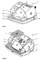
- Fig. 1 shows a perspective view of a known thermal transfer postage meter 1 * from the front and top right.
- the thermal transfer postage meter machine 1 * type Optimail has below a cash drawer in the feed 4 * an initial sensor 16 * - dashed lines, because hidden - with a microprocessor, however, can not reliably determine whether the envelope has already left the postage meter.
- It is equipped at the right side 7 * and at the upper part 10 * with a flap 5 * to the cassette compartment of the franking machine 1 *.
- the flap 5 * has an operating field 50 * to the opening.
- the supply and removal of a mailpiece takes place on the feed table 4 * at the contact edge 49 * on the front side of the franking machine 1 * from left to right.
- Fig. 2 shows a perspective view from the front and top right of a next generation thermal transfer postage meter 1.
- the thermal transfer franking machine 1 is provided at its right side 7 and at its upper part 10 with a flap 5 to the cassette compartment of the franking machine 1 and at its left side with a weighing plate 2 of a scale assembly.
- the flap 5 has an operating field 50 to the opening. All housing parts are for Example made of colored plastic. The supply and removal of a mail piece takes place on the feed table 4 of the franking machine on the front side of the franking machine 1 from left to right.
- FIG 3 shows a perspective view from the front and top right of a thermal transfer franking machine 1 with the flap 5 open.
- the flap 5 is shown unfolded in the direction of the upper part 10.
- the flap 5 has on its underside both sides arranged flap arms.
- the right housing outer wall 6 on the cassette compartment is on the one hand on the right side 7 in the right side wall of the upper shell of the postage meter and on the other hand in the right cover 60, wherein upwardly directed first gradations 62 are formed, which correspond to the flap shape on the underside thereof.
- the left housing outer wall 3 on the cassette compartment merges into the upper shell of the postage meter machine and, on the other hand, into the left-hand cover 30, wherein upward second steps 32 are formed, which correspond to the shape of the flap on its underside.
- the arms of the cassette flap 5 dive when closing the flap in a corresponding slot-shaped opening in the steps 32, 62 of the left and right cover 30, 60 a.
- the flap 5 has on the underside also a flap finger 53 as an actuating means for a mechanism which detects by means of a sensor (not visible) the position of the flap.
- the opening stroke of the flap is designed so that sufficient time for switching off the supply voltage is available before access to a chip reading unit or the removal of the ink ribbon cassette 8 is possible.
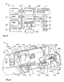
- Fig. 4 is a block diagram for controlling a thermal transfer printer with an end sensor for scanning the end of a mail piece.
- a microprocessor 21 is connected via a bus 25 to at least one nonvolatile memory 22, a pixel memory RAM 23, a read only memory FLASH 24 and a printer control module 26 connected in terms of address, data and control.
- An encoder 64 is connected to the print data controller 261 of the device 26 to synchronously trigger the buffering of the binary pixel data and the printing of the print image columns.
- An interface control 262 of the device 26 is for data input / output on the one hand with a chip reading unit 14, with a motor 65 for driving a mailing device in the transport direction, with a motor 66 for driving a winding mandrel for a take-up reel of the ink ribbon cassette and with a motor 67 for driving an actuator for a counter-pressure roller and on the other hand connected to sensors such as the start sensor 16, end sensor 19, an actuator sensor 36 for detecting the flap position / encoder position and an actuating sensor 68 of the actuator. Printing is started and franking is performed when a leading edge of a mail piece is detected by the head sensor 16.
- the end sensor 19 is positioned post-downstream of the printing device (9) and spaced from the start sensor 16 and sequentially detects leading edge and then the trailing edge of a transported mailpiece. Corresponding sensor signals reach the microprocessor of the microprocessor control 20, which by means of the printer control module 26, a motor operating voltage of the motor 65 turns off, which serves both to drive the conveying device for mail pieces in the transport direction and to drive the ejection roller 15. In addition, a motor operating voltage of the motor 66 for driving the winding mandrel is turned off.
- a thermal transfer printhead 9 is provided, as known per se, with a shift register, a memory latch unit and drive unit, and a series of thermal print heating elements arranged orthogonal to the mail piece transport direction. The thermal transfer printhead 9 is connected via the shift register to the serial data output of the print data controller 261, which takes over 16 bits of parallel binary print image data from the bus 25 on the input side and outputs binary print image data on the output side in a direct memory access.
- the encoder 3 is - optionally via the interface control 262 - connected to the print data controller 261 to synchronously trigger the buffering of the binary pixel data and printing the image columns, the print head is driven at a clock frequency which has a transport speed of about 150 mm per Second allowed for up to 6 mm thick pieces of mail.
- the main control board of a postage meter also includes other - not shown interfaces - for example, to connect a keyboard and a display unit, a smart card read / write unit, a modem and possibly a security module, which is also referred to as PSD (Postal Security Device).
- PSD Postal Security Device
- the PSD can be omitted.
- the printer controller 26 can be implemented with either an application specific circuit (ASIC) or programmable logic, such as the Spartan-II 2.5V Field Programmable Gate Array (FPGA) chip from XILINX (www.xilinx.com) .
- ASIC application specific circuit
- FPGA Field Programmable Gate Array
- An FPGA is an integrated circuit that contains many thousands of identical logic cells as standard components (up to 50,000 in the XC2S50 from XILINX). Each logic cell can independently assume any of a limited set of properties.
- the individual cells are interconnected by a matrix of lines and programmable switches.
- a user's design is introduced by specifying the simple logic function for each cell and selectively closing the switches in the join matrix. Complex designs are created by combining these basic blocks to create the desired circuit.
- These blocks form field programmable means whose advantageous function is to define the latter by a program of the user rather than by the manufacturer of the device.
- the program is either internally burned permanently or semi-permanently as part of a board compilation process, or is loaded from an external memory at any time when the aforementioned printing device is turned on.
- the configuration data for the FPGA XC2S50 comprise approx. 0.6 GBit and are stored in the read-only memory FLASH 24 (Fig.4).
- the use of an FPGA chip and related techniques offers the advantage that the programmable logic saves development costs and time over an increasingly complicated ASIC design, with the number of gates per FPGA chip now reaching numbers that support the implementation of allow more and more complicated applications. This allows for a high degree of freedom in programming hardware and software, with CAD tools deciding which parts of a source code program to run in software and which hardware parts.
- circuitry of the device 26 may be implemented by conventional technology, i. as hardwired circuit of logic gates positive and / or negative logic, can be realized.
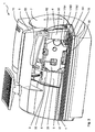
- Fig. 5 shows the perspective view of the cassette tray molding from the bottom front right.
- a respective mechanism located under the cover and steps of the housing upper shell is supported - not shown - between the left and right inner housing walls 172 and 171 and the left and right outer housing walls on the cassette compartment molding 17 on the chassis while associated sensors are molded onto each Support sensor carrier 174 and 175, respectively.
- the cassette flap position / encoder position sensor 36 is supported on the sensor tray 174 of the cassette tray molding 17 externally molded on the left housing inner wall 172.
- the interior (cassette tray) of the cassette tray molding 17 is defined by the right housing inner wall 171, the left housing inner wall 172, and the rear housing wall 173 limited.
- a formation 1731 at the edge between the left housing inner wall 172 and the inside of the housing rear wall 173 forms an outer wall of a channel for a slider, of which only its roof slope 434 is visible.
- a square opening 1732 in the housing back wall 173 takes the chip reading unit 14 on.
- a circular opening 1733 in the housing rear wall 173 is provided for the - not shown - Aufwickeldorn the cassette spool.
- the left housing inner wall 172 has an opening 18 and lateral guide means 1721 for correctly positioning the cassette during insertion.
- the right inner housing wall 172 also has lateral guide means.
- An upper housing wall 176 also has guide means 1761, 1762 as a positioning aid.
- the upper housing wall 176 merges laterally into the left and right housing inner walls and back into the housing rear wall 173 and not only stabilizes the cassette compartment, but also has molded fastening means (concealed) for the resilient locking element 11, at the free end of the pressure element 12 is formed ,
- a protruding into the interior of the cassette compartment frame 177 for the print head is integrally formed at the lower end of the housing rear wall 173 in the center.
- the space enclosed by the laterally molded-on sensor carriers 174 and 175, respectively, is closed at the bottom by a respective bottom plate 178, 179, which are respectively formed on the housing rear wall 173 between the left and right housing inner walls 172 and 171.
- the bottom plate 178 rises slightly outwardly relative to the feed table and terminates downstream in a thickened edge 1781 in front of the printhead frame 177.
- the bottom plate 179 behind the frame 177 begins with a thickening 1791, which receives idle rollers 1792 and 1792 and rotatably supports.
- the end sensor 19 is based here on the right of the cassette compartment molding 17 integrally formed sensor carrier 175.
- the actuator of the end sensor is designed as a sensor actuating lever 191 which rotatably disposed on a rotation axis 190 of the end sensor against a spring force and with a leg of a torsion spring 194 is connected.
- the triggering end of the sensor actuating lever 191 is adjacent to or exit the ejection roller 15. Opposite the triggering end of the sensor actuating lever 191, the sensor actuating lever passes into a disc 192, which from a Sensor electronics is scanned.
- the sensor electronics are housed in the sensor electronics housing 193. For example, a photointerrupter LG-413L sensor from Kodenshi Corp. is used. for use.
- the end sensor 19 can also be arranged in the housing lower shell or below an opening in the feed table. this having a sensor actuating lever 191 formed in such a way that its triggering end is positioned in the region of the ejection roller 15. Preferably, the triggering end passes next to the ejection roller 15 or the output of this.
- the sensor actuator is a resilient rotatably mounted sensor actuating lever 191.
- a sensor actuator is conceivable instead to detect a movement.
- the torsion spring 194 may then be omitted if necessary.
- the microprocessor control 20 is connected via a controller in the programmable printer control module 26 to the motor 65 for driving a mailpiece conveying device and to the other motors 66, 67 of the mailing device.
- a controller equipped with a field-programmable printer control module it is fundamentally possible to adapt it to any type of post-machine with different numbers of sensors and actuators or motors, even in the case of small quantities.
Landscapes
- Physics & Mathematics (AREA)
- General Physics & Mathematics (AREA)
- Devices For Checking Fares Or Tickets At Control Points (AREA)
- Pile Receivers (AREA)
- Particle Formation And Scattering Control In Inkjet Printers (AREA)
- Sorting Of Articles (AREA)
Abstract
Description
- Die Erfindung betrifft eine Anordnung für ein druckendes Postverarbeitungsgerät gemäß des Oberbegriffs des Anspruchs 1. Die Erfindung bezweckt den Durchsatz von Poststücken zu erhöhen. Die Erfindung kommt in Frankiermaschinen und in ähnlichen druckenden Buchungs- oder Postverarbeitungsgeräten zum Einsatz.
- Aus dem US 4.746.234 bzw. DD 233 101 B5 ist eine Thermotransfer-Frankiermaschine bekannt, in deren Poststücktransportpfad ein Anfang-sensor zum Erkennen einer Poststückvorderkannte bzw. eines Briefumschlaganfangs angeordnet und mit einem Mikroprozessor verbunden ist, um ein Drucken zu starten, sobald ein Poststück in den Druckbereich gelangt ist. Ein Thermotransferdruckkopf ist mit einem Schieberegister, einer Speicherlatcheinheit und Treibereinheit sowie mit einer Reihe an Thermodruckheizelementen ausgestattet, welche orthogonal zur Poststücktransportrichtung angeordnet ist. Der Thermotransferdruckkopf ist über das Schieberegister mit dem seriellen Datenausgang des Mikroprozessors verbunden. Die Mikroprozessorsteuerung kann mittels eines Encoders einen Farbbandweitertransport entsprechend der Transportgeschwindigkeit des Poststückes feststellen.
- Aus dem US 4.767.228, US 4.886.384 bzw. EP 189 984 B1 ist eine Farbbandkassette für Thermotransfer-Frankiermaschinen mit einem Fenster für ein Anlegen eines Reibrades an das Farbband und eine Poststücktransportvorrichtung bekannt, wie sie in ähnlicher Form bei modernen Thermotransfer-Frankiermaschinen vom Typ T1000 bzw. Optimal der Herstellerin Francotyp Postalia AG & Co.KG eingesetzt wird. Wenn eine Klappe zum Kassettenfach geöffnet wird, wird ein einfacher Mechanismus betätigt und das Reibrad vom Farbband der Kassette abgehoben, was es erlaubt, die Kassette zu entnehmen.
Aus dem US 5.710.721 bzw. EP 716 398 B1 ist eine mit einer für alle Frankiermaschinen gleichen ersten Mikroprozessorsteuerungsschaltung verbundene zweite frankiermaschineninterne Schnittstellenschaltung bekannt, die es erlaubt eine in Art und Anzahl dem Frankiermaschinen-Typ entsprechend variierbare Anzahl an Sensoren und Aktoren anzuschließen. Mit entsprechend unterschiedlichen anwenderspezifischen Schaltungen (ASIC's) wird eine Anpassung an unterschiedliche Druckverfahren ermöglicht. Jedoch müssen Produktionsstückzahlen für Frankiermaschinen gleichen Typs hoch sein, um die Kosten der Maskenprogrammierung der ASIC's zu rechtfertigen.
Bei Thermotransfer-Frankiermaschinen vom Typ T1000 bzw. Optimal ist eine Encoderscheibe auf derselben Achse wie ein Reibrad befestigt und wird folglich entsprechend letzterem ebenso gedreht, wenn das Farbband weiterbewegt wird. Der Betrieb der Maschine wird bei einem fehlenden Farbbandtransport oder nach Ablauf einer vorbestimmten Zeit nach dem Frankieren unterbrochen. Letztere wird auch Auswurfphase genannt. Bis zu 25 Poststücke pro Minute mit einer maximalen Dicke von 5mm können damit frankiert werden. Wenn der Frankiervorgang beendet ist, kann der Mikroprozessor der Frankiermaschine zwar mittels des Anfang-Sensors überprüfen, ob das Poststück, beispielsweise der Briefumschlag, noch im Druckbereich transportiert wird. Der Anfang-Sensor ist an der Anlegekante positioniert und der Mikroprozessor kann somit erkennen, ob der Briefumschlag noch an der Anlegekante anliegt. Falls es während des Frankierens durch Verdrehen des Briefumschlages dazu kommt, dass der Brief den Anfang-Sensor nicht mehr betätigt, dann wird während und nach der Frankierung der Briefumschlag nicht erkannt. Mit dem Anfang-Sensor kann der Mikroprozessor folglich nicht sicher erkennen, ob der Briefumschlag bereits die Frankiermaschine verlassen hat. Würde nun aufgrund der Abfrage dieses Anfang-Sensors der Auswurfvorgang beendet, kann der Briefumschlag in der Frankiermaschine liegen bleiben oder durch eine ungünstige Bewegung den Anfang-Sensor wiederholt, zum Beispiel mit der Hinterkannte des Briefumschlages, auslösen. Dies wurde bisher mit einer grundsätzlich langen Auswurfphase (ohne Abfrage des Anfang-Sensors) verhindert, führt aber zu einem geringeren Poststück-Durchsatz der Frankiermaschine.
Aus der Druckschrift US 2004/0021755 A1 ist bereits die Anordnung zusätzlicher Sensoren bekannt, um den Durchsatz an Poststücken zu erhöhen, indem Poststücke vor und nach dem Drucken schneller transportiert werden. - Die Aufgabe der Erfindung besteht darin, einen Sensor in einem druckenden Postverarbeitungsgerät so anzuordnen und mit der Steuerung zu verbinden, dass der Durchsatz von Poststücken unterschiedlicher Länge erhöht werden kann. Dabei soll eine mit der übrigen Schaltung der Mikroprozessorsteuerung verbundene maschineninterne Schnittstellenschaltung auch bei einer erhöhten Anzahl an Sensoren/Aktoren noch kostengünstig realisiert werden.
- Die Aufgabe wird mit den Merkmalen der Anordnung nach dem Anspruch 1 gelöst.
- In druckenden Postverarbeitungsgeräten werden die Poststücke relativ zum Druckkopf transportiert. Bei der Festlegung der Dauer der Auswurfphase des druckenden Postverarbeitungsgerätes musste bisher das Poststück mit den größten Abmaßen, zum Beispiel die Briefumschlaglänge Format B4 berücksichtigt werden. Ausgehend von den Ziel, die Auswurfphase zu verkürzen, wodurch das druckende Postverarbeitungsgerät schneller wieder bereit ist, einen nachfolgenden Briefumschlag zu bedrucken, basiert die Erfindung auf der Idee, einen (Briefumschlag-) Ende-Sensor einzusetzen, der erkennen kann, wann das Poststück (Briefumschlag) das druckende Postverarbeitungsgerät wirklich verlassen hat. Nach dieser Erkennung wird die Auswurfphase beendet und der (Briefumschlag-)Anfang-Sensor kann wieder abgefragt werden. Hierdurch ist die Länge der Auswurfphase von der Briefumschlaglänge abhängig und der nächste Briefumschlag kann bereits früher erkannt werden, um ein Bedrucken des folgenden Briefumschlags früher zu starten, falls die Länge des gegenwärtig bedruckten Briefumschlags nicht maximal ist.
- Der Ende-Sensor wird im Bereich der Auswurfrolle des druckenden Postverarbeitungsgerätes positioniert und eine Schaltungsanordnung zum Abfragen des Endes eines Poststückes mittels Ende-Sensor umfasst eine elektrische Verbindung des Ende-Sensors über einen speziell programmierbaren Druckersteuerungsbaustein mit einer Mikroprozessorsteuerung. Für den speziell programmierbaren Druckersteuerungsbaustein rechnen sich die Kosten der Maskenprogrammierung eines ASIC's bei höheren Stückzahlen an druckenden Postverarbeitungsgeräten. Bei kleinen Stückzahlen an druckenden Postverarbeitungsgeräten ist das aber nicht profitabel. Deshalb wird eine dort universelle räumlich und zeitlich wirksame unterschiedlich programmierbare Logik eingesetzt. Während die räumlich wirksame Programmierung, beispielsweise Feldprogrammierung, die innere Struktur der Logik festlegt, wird durch die zeitlich wirksame Programmierung der Ablauf und die Reihenfolge der Datenverarbeitung von Logikzellen innerhalb der Logik definiert. Die Erfindung wird zwar am Beispiel einer Frankiermaschine verdeutlicht, aber soll nicht allein darauf beschränkt bleiben.
- Vorteilhafte Weiterbildungen der Erfindung sind in den Unteransprüchen gekennzeichnet bzw. werden nachstehend zusammen mit der Beschreibung der bevorzugten Ausführung der Erfindung anhand der Figuren näher dargestellt. Es zeigen:
- Fig. 1,
- perspektivische Ansicht einer bekannten Thermotransfer-Frankiermaschine mit Klappe des Kassettenfachs (prior art),
- Fig. 2,
- perspektivische Ansicht von vorn und rechts oben einer Thermotransfer-Frankiermaschine der nächsten Generation,
- Fig. 3,
- perspektivische Ansicht der Thermotransfer-Frankiermaschine mit geöffneter Kassettenklappe,
- Fig. 4,
- Blockschaltbild zur Steuerung eines Thermotransferdruckers mit Ende-Sensor zum Abfragen des Endes eines Poststückes,
- Fig. 5,
- perspektivische Ansicht des Kassettenfachformteils von vorn unten rechts.
- Die Fig. 1 zeigt eine perspektivische Ansicht einer bekannten Thermotransfer-Frankiermaschine 1* von vorn und rechts oben. Die Thermotransfer-Frankiermaschine 1* vom Typ Optimail besitzt unterhalb eines Kassenfachs im Zuführtisch 4* einen Anfang-Sensor 16* - gestrichelt gezeichnet, da verdeckt -, mit dem ein Mikroprozessor jedoch nicht sicher erkennen kann, ob der Briefumschlag bereits die Frankiermaschine verlassen hat. Sie ist an deren rechten Seite 7* und an deren Oberteil 10* mit einer Klappe 5* zum Kassettenfach der Frankiermaschine 1* ausgestattet. Die Klappe 5* weist ein Betätigungsfeld 50* zu deren Öffnung auf. Die Zu- und Abführung eines Poststückes erfolgt auf dem Zuführtisch 4* an der Anlegekante 49* an der Vorderseite der Frankiermaschine 1* von links nach rechts.
- Die Fig. 2 zeigt eine perspektivische Ansicht von vorn und rechts oben einer Thermotransfer-Frankiermaschine 1 der nächsten Generation. Die Thermotransfer-Frankiermaschine 1 ist an deren rechten Seite 7 und an deren Oberteil 10 mit einer Klappe 5 zum Kassettenfach der Frankiermaschine 1 und an deren linken Seite mit einem Wiegeteller 2 einer Waagebaugruppe ausgestattet. Die Klappe 5 weist ein Betätigungsfeld 50 zu deren Öffnung auf. Alle Gehäuseteile sind zum Beispiel aus farbigem Kunststoff hergestellt. Die Zu- und Abführung eines Poststückes erfolgt auf dem Zuführtisch 4 der Frankiermaschine an der Vorderseite der Frankiermaschine 1 von links nach rechts.
- Die Fig. 3 zeigt eine perspektivische Ansicht von vorn und rechts oben einer Thermotransfer-Frankiermaschine 1 mit geöffneter Klappe 5. Die Klappe 5 ist in Richtung zum Oberteil 10 hin aufgeklappt dargestellt. Die Klappe 5 hat auf deren Unterseite beidseitig angeordnete Klappenarme. Die rechte Gehäuseaußenwand 6 am Kassettenfach geht einerseits auf der rechten Seite 7 in die rechte Seitenwand der Oberschale der Frankiermaschine und andererseits in die rechte Abdeckung 60 über, wobei nach oben gerichtete erste Abstufungen 62 ausgebildet sind, welche der Klappenform auf deren Unterseite entsprechen. Die linke Gehäuseaußenwand 3 am Kassettenfach geht andererseits in die Oberschale der Frankiermaschine und andererseits in die linke Abdeckung 30 über, wobei nach oben gerichtete zweite Abstufungen 32 ausgebildet sind, welche der Klappenform auf deren Unterseite entsprechen. Die Arme der Kassettenklappe 5 tauchen beim Schließen der Klappe in eine entsprechende schlitzförmige Öffnung in den Abstufungen 32, 62 der linken bzw. rechten Abdeckung 30, 60 ein. Die Klappe 5 hat auf deren Unterseite außerdem einen Klappenfinger 53 als Betätigungsmittel für einen Mechanismus, der mittels eines Sensors (nicht sichtbar) die Stellung der Klappe erkennt. Der Öffnungshub der Klappe ist so ausgelegt, das ausreichend Zeit zum Abschalten der Versorgungsspannung zur Verfügung steht, bevor ein Zugriff auf eine Chip-Leseeinheit bzw. die Entnahme der Farbbandkassette 8 möglich ist.
- Die Fig. 4 zeigt ein Blockschaltbild zur Steuerung eines Thermotransferdruckers mit Ende-Sensor zum Abfragen des Endes eines Poststückes. Ein Mikroprozessor 21 ist über einen Bus 25 mindestens mit einem nichtflüchtigen Speicher 22, einem Pixelspeicher-RAM 23, einem Festwertspeicher FLASH 24 sowie mit einem Druckersteuerungsbaustein 26 adress-, daten- und steuerungsmäßig verbunden. Ein Encoder 64 ist mit der Druckdatensteuerung 261 des Bausteins 26 verbunden, um das Zwischenspeichern der binären Pixeldaten und das Drucken der Druckbildspalten synchron auszulösen. Eine Interfacesteuerung 262 des Bausteins 26 ist zur Datenein-/ausgabe einerseits mit einer Chip-Leseeinheit 14, mit einem Motor 65 zum Antrieb einer Beförderungsvorrichtung für Poststücke in Transportrichtung, mit einem Motor 66 zum Antrieb eines Wickeldorns für eine Aufwickelspule der Farbbandkassette und mit einem Motor 67 zum Antrieb einer Betätigungsvorrichtung für eine Gegendruckrolle sowie andererseits mit Sensoren, wie dem Anfang-Sensor 16, Ende-Sensor 19, einem Betätigungssensor 36 zum Erkennen der Klappenstellung/Encoderposition und einem Betätigungssensor 68 der Betätigungsvorrichtung verbunden. Ein Drucken wird gestartet und eine Frankierung ausgeführt, wenn eine Vorderkante eines Poststückes durch den Anfang-Sensor 16 detektiert wird. Der Ende-Sensor 19 ist poststromabwärts der Druckeinrichtung (9) positioniert und im Abstand zum Anfang-Sensor 16 angeordnet und detektiert nacheinander Vorderkante und dann die Hinterkante eines transportierten Poststückes. Entsprechende Sensorsignale gelangen zum Mikroprozessor der Mikroprozessorsteuerung 20, welche mittels des Druckersteuerungsbausteins 26 eine Motorbetriebsspannung des Motors 65 abschaltet, der sowohl zum Antrieb der Beförderungsvorrichtung für Poststücke in Transportrichtung als auch zum Antrieb der Auswurfrolle 15 dient. Außerdem wird eine Motorbetriebsspannung des Motors 66 zum Antrieb des Wickeldorns abgeschaltet.
Ein Thermotransferdruckkopf 9 ist - in an sich bekannter Weise - mit einem Schieberegister, einer Speicherlatcheinheit und Treibereinheit sowie mit einer Reihe an Thermodruckheizelementen ausgestattet, welche orthogonal zur Poststücktransportrichtung angeordnet ist. Der Thermotransferdruckkopf 9 ist über das Schieberegister mit dem seriellen Datenausgang der Druckdatensteuerung 261 verbunden, welche bei einem direkten Speicherzugriff eingangsseitig 16 Bit parallel anliegende binäre Druckbilddaten vom BUS 25 übernimmt und ausgangsseitig seriell binäre Druckbilddaten abgibt. - Der Encoder 3 ist ― ggf. über die Interfacesteuerung 262 - mit der Druckdatensteuerung 261 verbunden, um das Zwischenspeichern der binären Pixeldaten und das Drucken der Druckbildspalten synchron auszulösen, wobei der Druckkopf mit einer Taktfrequenz angesteuert wird, die eine Transportgeschwindigkeit von ca.150 mm pro Sekunde für bis zu 6 mm dicke Poststücke erlaubt.
- Die Hauptsteuerleiterplatte einer Frankiermaschine enthält außerdem weitere - nicht gezeigte Schnittstellen - beispielsweise zum Anschluss einer Tastatur und einer Anzeigeeinheit, einer Chipkarten-Schreib-/Leseeinheit, eines Modems sowie ggf. eines Sicherheitsmoduls, das auch als PSD (Postal Security Device) bezeichnet wird. Für reine Druckaufgaben kann das PSD jedoch entfallen.
- Der Druckersteuerungsbaustein 26 kann entweder mit einer anwendungsspezifischen Schaltung (ASIC) oder mit einer programmierbaren Logik, wie beispielsweise der Field Programmable Gate Array (FPGA) Chipbaustein der Serie Spartan-II 2,5V der Firma XILINX (www.xilinx.com) realisiert werden. Ein Einsatz des FPGA gestattet die Kosten der Maskenprogrammierung der ASIC's einzusparen.
- Ein FPGA ist eine integrierte Schaltung, die viele tausend identische Logikzellen als Standardbestandteile enthält (bis 50000 beim XC2S50 der Firma XILINX). Jede Logikzelle kann unabhängig irgendeine aus einem begrenzten Satz an Beschaffenheiten annehmen. Die einzelnen Zellen werden durch eine Matrix der Leitungen und der programmierbaren Schalter zusammengeschalten. Das Design eines Benutzers wird eingeführt, indem man die einfache Logikfunktion für jede Zelle spezifiziert und selektiv die Schalter in der Verknüpfungsmatrix schließt. Komplizierte Designs werden verursacht, indem man diese grundlegenden Blöcke kombiniert, um den gewünschten Stromkreis zu verursachen. Diese Blöcke bilden feldprogrammierbare Mittel, deren vorteilhafte Funktion darin besteht, dass letztere von einem Programm des Benutzers anstatt vom Hersteller der Vorrichtung definiert wird. Das Programm wird entweder innen dauerhaft oder semipermanent als Teil eines Board-Zusammenstellungsprozesses gebrannt oder wird von einem externen Speicher zu jeden Zeit geladen, wenn die vorgenannte Druckvorrichtung eingeschaltet wird. Die Konfigurationsdaten für den FPGA XC2S50 umfassen ca. 0,6 GBit und werden im Festwertspeicher FLASH 24 (Fig.4) gespeichert. Die Verwendung eines FPGA-Chips und damit in Zusammenhang stehende Techniken bietet den Vorteil, dass die programmierbare Logik Entwicklungskosten und Zeit spart gegenüber einem in zunehmendem Maße komplizierten ASIC-Entwurf, wobei die Gatteranzahl pro FPGA-Chip inzwischen Anzahlen erreicht hat, welche die Implementierung von immer komplizierteren Anwendungen zulassen. Das erlaubt einen großen Grad an Programmierfreiheit in Hard- und Software, wobei CAD-Werkzeuge mitentscheiden, welche Teile eines Source Code-Programms in Software und welche Teile mit Hardware ausgeführt werden sollen.
- Weiterhin kann die Schaltungsanordnung des Bausteins 26 mittels herkömmlicher Technologie, d.h. als festverdrahtete Schaltung von Logikgattern positiver und/oder negativer Logik, realisiert werden.
- Die Fig. 5 zeigt die perspektivische Ansicht des Kassettenfachformteils von vorn unten rechts. Ein jeweiliger unter den Abdeckung und Abstufungen der Gehäuseoberschale befindlicher Mechanismus stützt sich - in nicht gezeigter Weise - zwischen der linken bzw. rechten Gehäuseinnenwand 172 bzw. 171 und der linken bzw. rechten Gehäuseaußenwand am Kassettenfachformteil 17 auf das Chassis während sich zugehörige Sensoren auf jeweils angeformte Sensor-Träger 174 bzw. 175 stützen. Der Sensor 36 zum Erkennen der Kassettenklappenstellung/Encoderposition stützt sich auf den an der linken Gehäuseinnenwand 172 außen angeformten Sensor-Träger 174 des Kassettenfachformteils 17. Der Innenraum (Kassettenfach) des Kassettenfachformteils 17 wird durch die rechte Gehäuseinnenwand 171, die linke Gehäuseinnenwand 172 und die Gehäuserückwand 173 begrenzt. Eine Ausformung 1731 an der Kante zwischen der linken Gehäuseinnenwand 172 und der Innenseite der Gehäuserückwand 173 bildet eine Außenwand eines Kanals für einen Schieber, von dem nur seine Dachschräge 434 sichtbar ist. Eine viereckige Öffnung 1732 in der Gehäuserückwand 173 nimmt die Chip-Leseeinheit 14 auf. Eine kreisrunde Öffnung 1733 in der Gehäuserückwand 173 ist für den - nicht gezeigten - Aufwickeldorn der Kassettenspule vorgesehen. Die linke Gehäuseinnenwand 172 weist eine Öffnung 18 und seitliche Führungsmittel 1721 zum korrekten Positionieren der Kassette beim Einlegen auf. Die rechte Gehäuseinnenwand 172 weist ebenfalls seitliche Führungsmittel auf. Eine obere Gehäusewand 176 weist ebenfalls Führungsmittel 1761, 1762 als Positionierhilfe auf. Die obere Gehäusewand 176 geht seitlich in die linke und rechte Gehäuseinnenwand und hinten in die Gehäuserückwand 173 über und stabilisiert nicht nur das Kassettenfach, sondern weist auch angeformte Befestigungsmittel (verdeckt) für das federnde Verriegelungselement 11 auf, an dessen freien Ende das Andruckelement 12 angeformt ist. Ein in den Innenraum des Kassettenfachs ragender Rahmen 177 für den Druckkopf ist am unteren Ende der Gehäuserückwand 173 in deren Mitte angeformt. Der von den seitlich angeformten Sensor-Träger 174 bzw. 175 umfasste Raum wird nach unten durch jeweils eine Bodenplatte 178, 179 abgeschlossen, die jeweils an der Gehäuserückwand 173 zwischen der linken bzw. rechten Gehäuseinnenwand 172 bzw. 171 angeformt sind. Für einen reibungsarmen Poststücktransport ist vorteilhaft, das die Bodenplatte 178 gegenüber dem Zuführtisch nach außen leicht ansteigt und poststromabwärts in eine verdickte Kante 1781 vor dem Rahmen 177 für den Druckkopf endet. Für den Auswurf der Poststücke ist es weiterhin vorteilhaft, das die Bodenplatte 179 hinter dem Rahmen 177 mit einer Verdickung 1791 beginnt, welche unangetriebene Rollen 1792 und 1792 aufnimmt und drehbar lagert.
Der Ende-Sensor 19 stützt sich hier auf den rechts am Kassettenfachformteil 17 angeformten Sensorträger 175. Das Betätigungselement des Ende-Sensors ist als Sensorbetätigungshebel 191 ausgebildelt, der auf einer Drehachse 190 des Ende-Sensors entgegen einer Federkraft drehbeweglich angeordnet und mit einem Schenkel einer Torsionsfeder 194 verbunden ist. Im montierten Zustand liegt das Auslöseende des Sensorbetätigungshebels 191 neben oder ausgangs der Auswurfrolle 15. Gegenüber dem Auslöseende des Sensorbetätigungshebels 191 geht der Sensorbetätigungshebel in eine Scheibe 192 über, welche von einer Sensorelektronik abgetastet wird. Die Sensorelektronik ist im Sensorelektronikgehäuse 193 untergebracht. Zum Beispiel kommt ein Sensor des Typs Photointerrupter LG-413L der Firma Kodenshi Corp. zum Einsatz. - Alternativ zur Anordnung am seitlich angeformten Sensor-Träger 175 des Kassettenfachformteils der Gehäuseoberschale kann der Ende-Sensor 19 auch in der Gehäuseunterschale bzw. unterhalb einer Öffnung im Zuführtisch angeordnet werden. wobei dieser einen derartig geformten Sensorbetätigungshebel 191 aufweist, dass dessen Auslöseende im Bereich der Auswurfrolle 15 positioniert ist. Vorzugsweise gelangt dessen Auslöseende neben die Auswurfrolle 15 oder ausgangs dieser.
- Vorteilhaft ist das Sensor-Betätigungselement ein federnder drehbar gelagerter Sensorbetätigungshebel 191. Jedoch sind stattdessen auch andere Ausformungen als Sensor-Betätigungselement denkbar, um eine Bewegung zu detektieren. Die Torsionsfeder 194 kann dann ggf. entfallen.
- Es ist vorgesehen, dass die Mikroprozessorsteuerung 20 über einen Controller im programmierbaren Druckersteuerungsbaustein 26 mit dem Motor 65 zum Antrieb einer Beförderungsvorrichtung für Poststücke sowie mit den weiteren Motoren 66, 67 des Postgerätes verbunden ist. Bei einer mit einem feldprogrammierbaren Druckersteuerungsbaustein ausgestatteten Steuerung ist grundsätzlich eine Anpassung an beliebige Postmaschinentypen mit unterschiedlichen Anzahlen an Sensoren und Aktoren bzw. Motoren auch bei kleinen Stückzahlen ökonomisch möglich.
- Somit können offensichtlich weitere andere Ausführungen der Erfindung entwickelt bzw. eingesetzt werden, die vom gleichen Grundgedanken der Erfindung ausgehen und von den anliegenden Ansprüchen umfasst werden.
-
- 1, 1*
- Thermotransfer-Frankiermaschine
- 2
- Wiegeteller
- 3
- linke Gehäuseaußenwand am Kassettenfach
- 30
- Abdeckung für linksseitigen Mechanismus der Kassettenaufnahme
- 31
- Schlitz-Öffnung für linken Klappenarm
- 32
- Abstufung der Abdeckung
- 36
- Sensor zum Erkennen d. Kassettenklappenstellung/Encoderposition
- 4,4*
- Zuführtisch der Frankiermaschine
- 434
- Dachschräge des Schieberflachkörpers,
- 49, 49*
- Briefkuvert-Anlegekante
- 5, 5*
- Klappe des Kassettenfachs
- 50,50*
- Betätigungsfeld
- 53
- Klappenfinger
- 59
- Gegendruckrolle
- 6
- rechte Gehäuseaußenwand am Kassettenfach
- 60
- Abdeckung für rechtsseitigen Mechanismus d. Kassettenaufnahme
- 61
- -
- 62
- Abstufung der Abdeckung,
- 63
- -
- 64
- Encoder,
- 65
- Motor zum Antrieb einer Beförderungsvorrichtung für Poststücke,
- 66
- Motor zum Antrieb eines Wickeldorns für eine Aufwickelspule,
- 67
- Motor zum Antrieb einer Betätigungsvorrichtung der Gegendruckrolle,
- 68
- Betätigungssensor der Betätigungsvorrichtung,
- 69
- -
- 7,7*
- rechte Seitenwand der Frankiermaschine
- 8
- Kassette
- 9
- Druckkopf, Druckeinrichtung
- 10, 10*
- Gehäuseoberteil
- 11
- Verriegelungselement für Kassette zum Positionieren der Kassette
- 12
- Andruckelement für Kassette zum Einprägen einer Kontaktkraft
- 14
- Chip-Leseeinheit
- 15
- angetriebene gefederte Auswurfrolle
- 16,16*
- Anfang-Sensor
- 17
- Kassettenfachformteil
- 171
- rechte Gehäuseinnenwand des Kassettenfachs
- 172
- linke Gehäuseinnenwand des Kassettenfachs
- 1721
- Führungsmittel,
- 173
- Gehäuserückwand des Kassettenfachs,
- 1731
- Außenwand des Kanals,
- 1732
- viereckige Öffnung in der Gehäuserückwand des Kassettenfachs,
- 1733
- kreisrunde Öffnung in der Gehäuserückwand des Kassettenfachs,
- 174
- linker Sensorträger,
- 175
- rechter Sensorträger,
- 176
- obere Gehäuserwand des Kassettenfachs,
- 1761
- Führungsmittel,
- 1762
- Führungsmittel,
- 177
- Rahmen für Druckkopf,
- 178
- Linke Bodenplatte,
- 1781
- verdickte Kante,
- 179
- rechte Bodenplatte,
- 1791
- Verdickung der rechten Bodenplatte,
- 1792, 1793
- unangetriebene Rollen,
- 18
- Öffnung für Reibrad,
- 19
- Ende-Sensor,
- 190
- Drehachse des Ende-Sensors
- 191
- Sensorbetätigungshebel
- 192
- Scheibe am Sensorbetätigungshebel
- 193
- Sensorelektronikgehäuse
- 194
- Torsionsfeder
- 20
- Schaltung der Mikroprozessorsteuerung,
- 21
- Mikroprozessor,
- 22
- nichtflüchtiger Speicher (NVM),
- 23
- flüchtiger Speicher (RAM),
- 24
- Programmspeicher (FLASH),
- 25
- BUS,
- 26
- Druckersteuerungsbaustein (feldprogramm.Baustein oder ASIC),
- 261
- Druckdatensteuerung,
- 262
- Interfacesteuerung,
Claims (8)
- Anordnung für ein druckendes Postverarbeitungsgerät (1), das einen Zuführtisch (4) für den Poststücktransport und einen Anfang-Sensor (16) im Zuführtisch (4) aufweist, der mit einer Mikroprozessorsteuerung (20) verbunden ist, um den Druckvorgang bei Poststückzuführung auszulösen, mit einer Druckeinrichtung (9), die zum mikroprozessorgesteuerten Drucken über dem Zuführtisch (4) angeordnet ist, mit einer angetriebenen Auswurfrolle (15) im Zuführtisch (4), gekennzeichnet dadurch, dass ein Ende-Sensor (19) im Bereich der Auswurfrolle (15) poststromabwärts der Druckeinrichtung (9) positioniert und mit der Mikroprozessorsteuerung (20) zum Abfragen eines Poststück-Endes verbunden ist, bei dessen Erkennung die Mikroprozessorsteuerung (20) eine zum Antrieb der Auswurfrolle (15) bereitgestellte Motorbetriebsspannung mittels eines Druckersteuerungsbausteins (26) abschaltet.
- Anordnung, nach Anspruch 1, gekennzeichnet dadurch, dass ein Sensorträger (175) an ein Kassettenfachformteil (17) angeformt ist und den Ende-Sensor (19) trägt, der ein Auswerfen eines Poststückes detektieren kann.
- Anordnung, nach den Ansprüchen 1 bis 2, gekennzeichnet dadurch, dass ein federnder drehbar gelagerter Sensorbetätigungshebel (191) zur Betätigung des Ende-Sensors (19) vorgesehen ist.
- Anordnung, nach Anspruch 1, gekennzeichnet dadurch, dass der Ende-Sensor (19) im Gehäuseunterteil bzw. in einer Öffnung im Zuführtisch (4) angeordnet ist und einen derartig geformten Sensorbetätigungshebel (191) aufweist, dass dessen Auslöseende im Bereich der Auswurfrolle (15) positioniert ist.
- Anordnung, nach Anspruch 1, gekennzeichnet dadurch, dass mindestens der Anfang-Sensor (16) und der im Auswurfbereich positionierte Ende-Sensor (19) über den programmierbaren Druckersteuerungsbaustein (26) mit der Mikroprozessorsteuerung (20) verbunden ist, und dass die Mikroprozessorsteuerung (20) über einen Controller im programmierbaren Druckersteuerungsbaustein (26) mit dem Motor (65) zum Antrieb einer Beförderungsvorrichtung für Poststücke verbunden ist.
- Anordnung, nach den Ansprüchen 1 und 5, gekennzeichnet dadurch, dass mindestens der Anfang-Sensor (16), Ende-Sensor (19) über eine interne Interfacesteuerung (262) des Druckersteuerungsbausteins (26) mit der Mikroprozessorsteuerung (20) verbunden ist.
- Anordnung, nach den Ansprüchen 1 und 5, gekennzeichnet dadurch, dass der Druckersteuerungsbaustein (26) ein feldprogrammierbarer Baustein (FPGA) ist.
- Anordnung, nach den Ansprüchen 1 und 5, gekennzeichnet dadurch, dass der Druckersteuerungsbaustein (26) ein anwenderspezifisch integrierter Schaltkreis (ASIC) ist.
Applications Claiming Priority (1)
| Application Number | Priority Date | Filing Date | Title |
|---|---|---|---|
| DE202004015279U DE202004015279U1 (de) | 2004-10-01 | 2004-10-01 | Anordnung für ein druckendes Postverarbeitungsgerät |
Publications (2)
| Publication Number | Publication Date |
|---|---|
| EP1643455A1 true EP1643455A1 (de) | 2006-04-05 |
| EP1643455B1 EP1643455B1 (de) | 2007-07-18 |
Family
ID=34072240
Family Applications (1)
| Application Number | Title | Priority Date | Filing Date |
|---|---|---|---|
| EP05020746A Expired - Lifetime EP1643455B1 (de) | 2004-10-01 | 2005-09-23 | Anordnung für ein druckendes Postverarbeitungsgerät |
Country Status (4)
| Country | Link |
|---|---|
| US (1) | US7411599B2 (de) |
| EP (1) | EP1643455B1 (de) |
| AT (1) | ATE367624T1 (de) |
| DE (2) | DE202004015279U1 (de) |
Families Citing this family (2)
| Publication number | Priority date | Publication date | Assignee | Title |
|---|---|---|---|---|
| DE102006009334A1 (de) | 2006-03-01 | 2007-09-20 | Francotyp-Postalia Gmbh | Verfahren zur Qualitätsverbesserung des Druckens mit einem Thermotransferdruckkopf und Anordnung zur Durchführung des Verfahrens |
| US8294946B2 (en) * | 2006-06-12 | 2012-10-23 | Hewlett-Packard Development Company, L.P. | Printer |
Citations (6)
| Publication number | Priority date | Publication date | Assignee | Title |
|---|---|---|---|---|
| US3915089A (en) * | 1974-06-05 | 1975-10-28 | Pitney Bowes Inc | Movable imprinting deck mechanism |
| US4083555A (en) * | 1977-04-11 | 1978-04-11 | Pitney-Bowes, Inc. | Sheet-material separator and feeder system |
| US4767228A (en) * | 1985-01-19 | 1988-08-30 | Francotyp-Postalia Gmbh | Ribbon cassettes |
| EP0716398A2 (de) * | 1994-12-07 | 1996-06-12 | Francotyp-Postalia GmbH | Frankiermaschineninterne Schnittstellenschaltung und Verfahren zur manipulationssicheren Druckdatensteuerung |
| US6241235B1 (en) * | 1998-08-05 | 2001-06-05 | Francotyp-Postalia Ag & Co. | Apparatus for separating printed media |
| US6364306B1 (en) * | 1999-03-13 | 2002-04-02 | Francotyp Postalia Ag & Co. | Configuration for determining the dimensions of printed media |
Family Cites Families (5)
| Publication number | Priority date | Publication date | Assignee | Title |
|---|---|---|---|---|
| US4093555A (en) * | 1974-01-30 | 1978-06-06 | Espe Fabrik Pharmazeutischer Praparate Gmbh | Production of dental models and tooth replacement parts |
| GB2144081B (en) * | 1983-07-23 | 1987-10-28 | Pa Consulting Services | Postal franking machines |
| US6783290B2 (en) * | 2002-08-05 | 2004-08-31 | Pitney Bowes Inc. | Method and system for high speed digital metering using low velocity print technology |
| US7264323B2 (en) * | 2002-11-22 | 2007-09-04 | Codonics, Inc. | Achieving laser-quality medical hardcopy output from thermal print devices |
| JP4319002B2 (ja) * | 2003-10-16 | 2009-08-26 | セイコーインスツル株式会社 | 熱活性装置 |
-
2004
- 2004-10-01 DE DE202004015279U patent/DE202004015279U1/de not_active Expired - Lifetime
-
2005
- 2005-09-21 US US11/232,396 patent/US7411599B2/en not_active Expired - Fee Related
- 2005-09-23 DE DE502005001044T patent/DE502005001044D1/de not_active Expired - Lifetime
- 2005-09-23 EP EP05020746A patent/EP1643455B1/de not_active Expired - Lifetime
- 2005-09-23 AT AT05020746T patent/ATE367624T1/de active
Patent Citations (6)
| Publication number | Priority date | Publication date | Assignee | Title |
|---|---|---|---|---|
| US3915089A (en) * | 1974-06-05 | 1975-10-28 | Pitney Bowes Inc | Movable imprinting deck mechanism |
| US4083555A (en) * | 1977-04-11 | 1978-04-11 | Pitney-Bowes, Inc. | Sheet-material separator and feeder system |
| US4767228A (en) * | 1985-01-19 | 1988-08-30 | Francotyp-Postalia Gmbh | Ribbon cassettes |
| EP0716398A2 (de) * | 1994-12-07 | 1996-06-12 | Francotyp-Postalia GmbH | Frankiermaschineninterne Schnittstellenschaltung und Verfahren zur manipulationssicheren Druckdatensteuerung |
| US6241235B1 (en) * | 1998-08-05 | 2001-06-05 | Francotyp-Postalia Ag & Co. | Apparatus for separating printed media |
| US6364306B1 (en) * | 1999-03-13 | 2002-04-02 | Francotyp Postalia Ag & Co. | Configuration for determining the dimensions of printed media |
Also Published As
| Publication number | Publication date |
|---|---|
| DE502005001044D1 (de) | 2007-08-30 |
| US7411599B2 (en) | 2008-08-12 |
| ATE367624T1 (de) | 2007-08-15 |
| EP1643455B1 (de) | 2007-07-18 |
| DE202004015279U1 (de) | 2005-01-13 |
| US20060087549A1 (en) | 2006-04-27 |
Similar Documents
| Publication | Publication Date | Title |
|---|---|---|
| EP0716398B1 (de) | Frankiermaschineninterne Schnittstellenschaltung | |
| DE69813036T2 (de) | Verfahren und Vorrichtung zur Verarbeitung von eingebetteter Information aufweisende Aufzeichnungsmedien | |
| DE69115132T2 (de) | Automatischer Postschalter. | |
| US5462375A (en) | Printer and data processing apparatus having printing unit | |
| DE2501035A1 (de) | Frankiermaschine mit einer druckfarbe ausstossenden postwertzeichendruckvorrichtung | |
| DE69117197T2 (de) | Aufzeichnungsgerät zur Durchführung einer Aufzeichnung mittels Tintenstrahlaufzeichnungskopf | |
| EP1696390B1 (de) | Verfahren und Anordnung zum Steuern des Druckens eines Thermotransferdruckgerätes | |
| DE69922718T2 (de) | Schreibträgermechanismus, Druckgerät mit diesem Schreibträgermechanismus und Verfahren zur Steuerung des Druckgerätes | |
| US5980030A (en) | Printer | |
| DE2230671A1 (de) | Manuell einstellbarer drucker | |
| EP1416430B1 (de) | Anordnung zum Drucken eines Druckbildes mit Bereichen unterschiedlicher Druckbildauflösung | |
| EP1643455B1 (de) | Anordnung für ein druckendes Postverarbeitungsgerät | |
| DE19740397A1 (de) | Postbearbeitungssystem mit einer Frankier- und Adressiermaschine und Verfahren zum kombinierten Frankier- und Adressendruck | |
| DE60128163T2 (de) | Tintenstrahldrucker | |
| DE69418130T2 (de) | Vorrichtung zum Abtasten der Oberflächenkontur von Poststücken | |
| DE2929815A1 (de) | Einzeilendrucker fuer gueltigkeitsbescheinigung | |
| DE3233425C2 (de) | ||
| DE19740396A1 (de) | Druckeinrichtung und Verfahren für den Druck auf einen Druckträger | |
| DE69810016T2 (de) | Schablonendruckmaschine | |
| DE3841235C2 (de) | Druckrad-Einstellvorrichtung | |
| DE202018102465U1 (de) | Gutverarbeitungsgerät mit einem Tintenstrahldruckkopf | |
| DE102006009334A1 (de) | Verfahren zur Qualitätsverbesserung des Druckens mit einem Thermotransferdruckkopf und Anordnung zur Durchführung des Verfahrens | |
| DE3888227T2 (de) | Druckgerät mit Buchstabenlöschvorrichtung. | |
| DE2350552C3 (de) | Typenhebelantriebseinrichtung | |
| DE102004027517B4 (de) | Anordnung und Verfahren zur Ansteuerung eines Thermotransferdruckkopfes |
Legal Events
| Date | Code | Title | Description |
|---|---|---|---|
| PUAI | Public reference made under article 153(3) epc to a published international application that has entered the european phase |
Free format text: ORIGINAL CODE: 0009012 |
|
| AK | Designated contracting states |
Kind code of ref document: A1 Designated state(s): AT BE BG CH CY CZ DE DK EE ES FI FR GB GR HU IE IS IT LI LT LU LV MC NL PL PT RO SE SI SK TR |
|
| AX | Request for extension of the european patent |
Extension state: AL BA HR MK YU |
|
| 17P | Request for examination filed |
Effective date: 20060421 |
|
| AKX | Designation fees paid |
Designated state(s): AT BE BG CH CY CZ DE DK EE ES FI FR GB GR HU IE IS IT LI LT LU LV MC NL PL PT RO SE SI SK TR |
|
| GRAP | Despatch of communication of intention to grant a patent |
Free format text: ORIGINAL CODE: EPIDOSNIGR1 |
|
| GRAS | Grant fee paid |
Free format text: ORIGINAL CODE: EPIDOSNIGR3 |
|
| GRAA | (expected) grant |
Free format text: ORIGINAL CODE: 0009210 |
|
| AK | Designated contracting states |
Kind code of ref document: B1 Designated state(s): AT BE BG CH CY CZ DE DK EE ES FI FR GB GR HU IE IS IT LI LT LU LV MC NL PL PT RO SE SI SK TR |
|
| REG | Reference to a national code |
Ref country code: GB Ref legal event code: FG4D Free format text: NOT ENGLISH |
|
| REG | Reference to a national code |
Ref country code: CH Ref legal event code: EP |
|
| REF | Corresponds to: |
Ref document number: 502005001044 Country of ref document: DE Date of ref document: 20070830 Kind code of ref document: P |
|
| REG | Reference to a national code |
Ref country code: IE Ref legal event code: FG4D Free format text: LANGUAGE OF EP DOCUMENT: GERMAN |
|
| GBT | Gb: translation of ep patent filed (gb section 77(6)(a)/1977) |
Effective date: 20070919 |
|
| ET | Fr: translation filed | ||
| PG25 | Lapsed in a contracting state [announced via postgrant information from national office to epo] |
Ref country code: PT Free format text: LAPSE BECAUSE OF FAILURE TO SUBMIT A TRANSLATION OF THE DESCRIPTION OR TO PAY THE FEE WITHIN THE PRESCRIBED TIME-LIMIT Effective date: 20071218 Ref country code: BG Free format text: LAPSE BECAUSE OF FAILURE TO SUBMIT A TRANSLATION OF THE DESCRIPTION OR TO PAY THE FEE WITHIN THE PRESCRIBED TIME-LIMIT Effective date: 20071018 Ref country code: IS Free format text: LAPSE BECAUSE OF FAILURE TO SUBMIT A TRANSLATION OF THE DESCRIPTION OR TO PAY THE FEE WITHIN THE PRESCRIBED TIME-LIMIT Effective date: 20071118 Ref country code: FI Free format text: LAPSE BECAUSE OF FAILURE TO SUBMIT A TRANSLATION OF THE DESCRIPTION OR TO PAY THE FEE WITHIN THE PRESCRIBED TIME-LIMIT Effective date: 20070718 Ref country code: LT Free format text: LAPSE BECAUSE OF FAILURE TO SUBMIT A TRANSLATION OF THE DESCRIPTION OR TO PAY THE FEE WITHIN THE PRESCRIBED TIME-LIMIT Effective date: 20070718 Ref country code: ES Free format text: LAPSE BECAUSE OF FAILURE TO SUBMIT A TRANSLATION OF THE DESCRIPTION OR TO PAY THE FEE WITHIN THE PRESCRIBED TIME-LIMIT Effective date: 20071029 |
|
| PG25 | Lapsed in a contracting state [announced via postgrant information from national office to epo] |
Ref country code: PL Free format text: LAPSE BECAUSE OF FAILURE TO SUBMIT A TRANSLATION OF THE DESCRIPTION OR TO PAY THE FEE WITHIN THE PRESCRIBED TIME-LIMIT Effective date: 20070718 |
|
| REG | Reference to a national code |
Ref country code: IE Ref legal event code: FD4D |
|
| BERE | Be: lapsed |
Owner name: FRANCOTYP-POSTALIA G.M.B.H. Effective date: 20070930 |
|
| PG25 | Lapsed in a contracting state [announced via postgrant information from national office to epo] |
Ref country code: LV Free format text: LAPSE BECAUSE OF FAILURE TO SUBMIT A TRANSLATION OF THE DESCRIPTION OR TO PAY THE FEE WITHIN THE PRESCRIBED TIME-LIMIT Effective date: 20070718 |
|
| PG25 | Lapsed in a contracting state [announced via postgrant information from national office to epo] |
Ref country code: DK Free format text: LAPSE BECAUSE OF FAILURE TO SUBMIT A TRANSLATION OF THE DESCRIPTION OR TO PAY THE FEE WITHIN THE PRESCRIBED TIME-LIMIT Effective date: 20070718 Ref country code: MC Free format text: LAPSE BECAUSE OF NON-PAYMENT OF DUE FEES Effective date: 20070930 Ref country code: GR Free format text: LAPSE BECAUSE OF FAILURE TO SUBMIT A TRANSLATION OF THE DESCRIPTION OR TO PAY THE FEE WITHIN THE PRESCRIBED TIME-LIMIT Effective date: 20071019 |
|
| PLBE | No opposition filed within time limit |
Free format text: ORIGINAL CODE: 0009261 |
|
| STAA | Information on the status of an ep patent application or granted ep patent |
Free format text: STATUS: NO OPPOSITION FILED WITHIN TIME LIMIT |
|
| PG25 | Lapsed in a contracting state [announced via postgrant information from national office to epo] |
Ref country code: CZ Free format text: LAPSE BECAUSE OF FAILURE TO SUBMIT A TRANSLATION OF THE DESCRIPTION OR TO PAY THE FEE WITHIN THE PRESCRIBED TIME-LIMIT Effective date: 20070718 Ref country code: IE Free format text: LAPSE BECAUSE OF FAILURE TO SUBMIT A TRANSLATION OF THE DESCRIPTION OR TO PAY THE FEE WITHIN THE PRESCRIBED TIME-LIMIT Effective date: 20070718 Ref country code: SK Free format text: LAPSE BECAUSE OF FAILURE TO SUBMIT A TRANSLATION OF THE DESCRIPTION OR TO PAY THE FEE WITHIN THE PRESCRIBED TIME-LIMIT Effective date: 20070718 |
|
| 26N | No opposition filed |
Effective date: 20080421 |
|
| PG25 | Lapsed in a contracting state [announced via postgrant information from national office to epo] |
Ref country code: SE Free format text: LAPSE BECAUSE OF FAILURE TO SUBMIT A TRANSLATION OF THE DESCRIPTION OR TO PAY THE FEE WITHIN THE PRESCRIBED TIME-LIMIT Effective date: 20071018 Ref country code: RO Free format text: LAPSE BECAUSE OF FAILURE TO SUBMIT A TRANSLATION OF THE DESCRIPTION OR TO PAY THE FEE WITHIN THE PRESCRIBED TIME-LIMIT Effective date: 20070718 |
|
| PG25 | Lapsed in a contracting state [announced via postgrant information from national office to epo] |
Ref country code: BE Free format text: LAPSE BECAUSE OF NON-PAYMENT OF DUE FEES Effective date: 20070930 |
|
| PG25 | Lapsed in a contracting state [announced via postgrant information from national office to epo] |
Ref country code: EE Free format text: LAPSE BECAUSE OF FAILURE TO SUBMIT A TRANSLATION OF THE DESCRIPTION OR TO PAY THE FEE WITHIN THE PRESCRIBED TIME-LIMIT Effective date: 20070718 |
|
| PG25 | Lapsed in a contracting state [announced via postgrant information from national office to epo] |
Ref country code: SI Free format text: LAPSE BECAUSE OF FAILURE TO SUBMIT A TRANSLATION OF THE DESCRIPTION OR TO PAY THE FEE WITHIN THE PRESCRIBED TIME-LIMIT Effective date: 20070718 |
|
| PG25 | Lapsed in a contracting state [announced via postgrant information from national office to epo] |
Ref country code: CY Free format text: LAPSE BECAUSE OF FAILURE TO SUBMIT A TRANSLATION OF THE DESCRIPTION OR TO PAY THE FEE WITHIN THE PRESCRIBED TIME-LIMIT Effective date: 20070718 |
|
| PG25 | Lapsed in a contracting state [announced via postgrant information from national office to epo] |
Ref country code: LU Free format text: LAPSE BECAUSE OF NON-PAYMENT OF DUE FEES Effective date: 20070923 |
|
| PG25 | Lapsed in a contracting state [announced via postgrant information from national office to epo] |
Ref country code: HU Free format text: LAPSE BECAUSE OF FAILURE TO SUBMIT A TRANSLATION OF THE DESCRIPTION OR TO PAY THE FEE WITHIN THE PRESCRIBED TIME-LIMIT Effective date: 20080119 Ref country code: TR Free format text: LAPSE BECAUSE OF FAILURE TO SUBMIT A TRANSLATION OF THE DESCRIPTION OR TO PAY THE FEE WITHIN THE PRESCRIBED TIME-LIMIT Effective date: 20070718 |
|
| REG | Reference to a national code |
Ref country code: DE Ref legal event code: R084 Ref document number: 502005001044 Country of ref document: DE Effective date: 20130620 Ref country code: GB Ref legal event code: 746 Effective date: 20130722 |
|
| REG | Reference to a national code |
Ref country code: DE Ref legal event code: R081 Ref document number: 502005001044 Country of ref document: DE Owner name: FRANCOTYP-POSTALIA GMBH, DE Free format text: FORMER OWNER: FRANCOTYP-POSTALIA GMBH, 16547 BIRKENWERDER, DE Effective date: 20150330 |
|
| REG | Reference to a national code |
Ref country code: FR Ref legal event code: PLFP Year of fee payment: 12 |
|
| REG | Reference to a national code |
Ref country code: FR Ref legal event code: PLFP Year of fee payment: 13 |
|
| PGFP | Annual fee paid to national office [announced via postgrant information from national office to epo] |
Ref country code: CH Payment date: 20170921 Year of fee payment: 13 Ref country code: GB Payment date: 20170921 Year of fee payment: 13 Ref country code: DE Payment date: 20170802 Year of fee payment: 13 Ref country code: FR Payment date: 20170928 Year of fee payment: 13 |
|
| PGFP | Annual fee paid to national office [announced via postgrant information from national office to epo] |
Ref country code: NL Payment date: 20170921 Year of fee payment: 13 Ref country code: AT Payment date: 20170922 Year of fee payment: 13 |
|
| PGFP | Annual fee paid to national office [announced via postgrant information from national office to epo] |
Ref country code: IT Payment date: 20170926 Year of fee payment: 13 |
|
| REG | Reference to a national code |
Ref country code: DE Ref legal event code: R119 Ref document number: 502005001044 Country of ref document: DE |
|
| REG | Reference to a national code |
Ref country code: CH Ref legal event code: PL |
|
| REG | Reference to a national code |
Ref country code: NL Ref legal event code: MM Effective date: 20181001 |
|
| REG | Reference to a national code |
Ref country code: AT Ref legal event code: MM01 Ref document number: 367624 Country of ref document: AT Kind code of ref document: T Effective date: 20180923 |
|
| GBPC | Gb: european patent ceased through non-payment of renewal fee |
Effective date: 20180923 |
|
| PG25 | Lapsed in a contracting state [announced via postgrant information from national office to epo] |
Ref country code: NL Free format text: LAPSE BECAUSE OF NON-PAYMENT OF DUE FEES Effective date: 20181001 |
|
| PG25 | Lapsed in a contracting state [announced via postgrant information from national office to epo] |
Ref country code: DE Free format text: LAPSE BECAUSE OF NON-PAYMENT OF DUE FEES Effective date: 20190402 Ref country code: IT Free format text: LAPSE BECAUSE OF NON-PAYMENT OF DUE FEES Effective date: 20180923 |
|
| PG25 | Lapsed in a contracting state [announced via postgrant information from national office to epo] |
Ref country code: LI Free format text: LAPSE BECAUSE OF NON-PAYMENT OF DUE FEES Effective date: 20180930 Ref country code: FR Free format text: LAPSE BECAUSE OF NON-PAYMENT OF DUE FEES Effective date: 20180930 Ref country code: CH Free format text: LAPSE BECAUSE OF NON-PAYMENT OF DUE FEES Effective date: 20180930 |
|
| PG25 | Lapsed in a contracting state [announced via postgrant information from national office to epo] |
Ref country code: AT Free format text: LAPSE BECAUSE OF NON-PAYMENT OF DUE FEES Effective date: 20180923 Ref country code: GB Free format text: LAPSE BECAUSE OF NON-PAYMENT OF DUE FEES Effective date: 20180923 |