EP1643088B1 - Method and device for the lubrication of an internal combustion engine - Google Patents
Method and device for the lubrication of an internal combustion engine Download PDFInfo
- Publication number
- EP1643088B1 EP1643088B1 EP05028621A EP05028621A EP1643088B1 EP 1643088 B1 EP1643088 B1 EP 1643088B1 EP 05028621 A EP05028621 A EP 05028621A EP 05028621 A EP05028621 A EP 05028621A EP 1643088 B1 EP1643088 B1 EP 1643088B1
- Authority
- EP
- European Patent Office
- Prior art keywords
- sensor
- lubricant
- cylinder
- lubricant film
- thickness
- Prior art date
- Legal status (The legal status is an assumption and is not a legal conclusion. Google has not performed a legal analysis and makes no representation as to the accuracy of the status listed.)
- Not-in-force
Links
- 238000000034 method Methods 0.000 title claims abstract description 45
- 238000002485 combustion reaction Methods 0.000 title claims description 51
- 238000005461 lubrication Methods 0.000 title claims description 25
- 239000000314 lubricant Substances 0.000 claims abstract description 215
- 230000001105 regulatory effect Effects 0.000 claims abstract description 6
- 239000000446 fuel Substances 0.000 claims description 14
- 239000000463 material Substances 0.000 claims description 11
- 239000000203 mixture Substances 0.000 claims description 6
- 230000006698 induction Effects 0.000 claims description 5
- 239000000126 substance Substances 0.000 claims description 4
- 230000013011 mating Effects 0.000 description 16
- 239000010687 lubricating oil Substances 0.000 description 13
- 230000001965 increasing effect Effects 0.000 description 8
- 230000001050 lubricating effect Effects 0.000 description 8
- NINIDFKCEFEMDL-UHFFFAOYSA-N Sulfur Chemical compound [S] NINIDFKCEFEMDL-UHFFFAOYSA-N 0.000 description 7
- 239000002253 acid Substances 0.000 description 7
- 238000005259 measurement Methods 0.000 description 7
- 229910052717 sulfur Inorganic materials 0.000 description 7
- 239000011593 sulfur Substances 0.000 description 7
- 230000000875 corresponding effect Effects 0.000 description 6
- 238000002604 ultrasonography Methods 0.000 description 6
- 230000000694 effects Effects 0.000 description 5
- 230000008859 change Effects 0.000 description 4
- 238000001816 cooling Methods 0.000 description 4
- 238000002592 echocardiography Methods 0.000 description 4
- 230000008569 process Effects 0.000 description 4
- 230000002000 scavenging effect Effects 0.000 description 4
- 230000005236 sound signal Effects 0.000 description 4
- 230000002159 abnormal effect Effects 0.000 description 3
- 230000006378 damage Effects 0.000 description 3
- 230000001419 dependent effect Effects 0.000 description 3
- 238000009826 distribution Methods 0.000 description 3
- 238000011156 evaluation Methods 0.000 description 3
- 238000012423 maintenance Methods 0.000 description 3
- 229910052751 metal Inorganic materials 0.000 description 3
- 239000002184 metal Substances 0.000 description 3
- 150000002739 metals Chemical class 0.000 description 3
- 238000006386 neutralization reaction Methods 0.000 description 3
- 238000012545 processing Methods 0.000 description 3
- XLYOFNOQVPJJNP-UHFFFAOYSA-N water Substances O XLYOFNOQVPJJNP-UHFFFAOYSA-N 0.000 description 3
- 150000007513 acids Chemical class 0.000 description 2
- 238000013016 damping Methods 0.000 description 2
- 230000002950 deficient Effects 0.000 description 2
- 238000001514 detection method Methods 0.000 description 2
- 230000003993 interaction Effects 0.000 description 2
- 239000002245 particle Substances 0.000 description 2
- 230000009467 reduction Effects 0.000 description 2
- 230000004044 response Effects 0.000 description 2
- 238000001228 spectrum Methods 0.000 description 2
- 230000002269 spontaneous effect Effects 0.000 description 2
- 229910000831 Steel Inorganic materials 0.000 description 1
- 230000006835 compression Effects 0.000 description 1
- 238000007906 compression Methods 0.000 description 1
- 230000001276 controlling effect Effects 0.000 description 1
- 238000005314 correlation function Methods 0.000 description 1
- 230000008878 coupling Effects 0.000 description 1
- 238000010168 coupling process Methods 0.000 description 1
- 238000005859 coupling reaction Methods 0.000 description 1
- 230000007812 deficiency Effects 0.000 description 1
- 230000030808 detection of mechanical stimulus involved in sensory perception of sound Effects 0.000 description 1
- 238000011161 development Methods 0.000 description 1
- 239000002360 explosive Substances 0.000 description 1
- 230000004907 flux Effects 0.000 description 1
- 230000001939 inductive effect Effects 0.000 description 1
- 238000002347 injection Methods 0.000 description 1
- 239000007924 injection Substances 0.000 description 1
- 238000007726 management method Methods 0.000 description 1
- 230000035699 permeability Effects 0.000 description 1
- 230000010287 polarization Effects 0.000 description 1
- 230000009528 severe injury Effects 0.000 description 1
- 239000000243 solution Substances 0.000 description 1
- 239000010959 steel Substances 0.000 description 1
- 230000002123 temporal effect Effects 0.000 description 1
- 230000001550 time effect Effects 0.000 description 1
- 238000012549 training Methods 0.000 description 1
- 238000003466 welding Methods 0.000 description 1
- 229910000859 α-Fe Inorganic materials 0.000 description 1
Images


Classifications
-
- F—MECHANICAL ENGINEERING; LIGHTING; HEATING; WEAPONS; BLASTING
- F01—MACHINES OR ENGINES IN GENERAL; ENGINE PLANTS IN GENERAL; STEAM ENGINES
- F01M—LUBRICATING OF MACHINES OR ENGINES IN GENERAL; LUBRICATING INTERNAL COMBUSTION ENGINES; CRANKCASE VENTILATING
- F01M1/00—Pressure lubrication
- F01M1/18—Indicating or safety devices
- F01M1/20—Indicating or safety devices concerning lubricant pressure
-
- F—MECHANICAL ENGINEERING; LIGHTING; HEATING; WEAPONS; BLASTING
- F01—MACHINES OR ENGINES IN GENERAL; ENGINE PLANTS IN GENERAL; STEAM ENGINES
- F01M—LUBRICATING OF MACHINES OR ENGINES IN GENERAL; LUBRICATING INTERNAL COMBUSTION ENGINES; CRANKCASE VENTILATING
- F01M1/00—Pressure lubrication
- F01M1/08—Lubricating systems characterised by the provision therein of lubricant jetting means
-
- F—MECHANICAL ENGINEERING; LIGHTING; HEATING; WEAPONS; BLASTING
- F01—MACHINES OR ENGINES IN GENERAL; ENGINE PLANTS IN GENERAL; STEAM ENGINES
- F01M—LUBRICATING OF MACHINES OR ENGINES IN GENERAL; LUBRICATING INTERNAL COMBUSTION ENGINES; CRANKCASE VENTILATING
- F01M1/00—Pressure lubrication
- F01M1/16—Controlling lubricant pressure or quantity
-
- F—MECHANICAL ENGINEERING; LIGHTING; HEATING; WEAPONS; BLASTING
- F02—COMBUSTION ENGINES; HOT-GAS OR COMBUSTION-PRODUCT ENGINE PLANTS
- F02F—CYLINDERS, PISTONS OR CASINGS, FOR COMBUSTION ENGINES; ARRANGEMENTS OF SEALINGS IN COMBUSTION ENGINES
- F02F1/00—Cylinders; Cylinder heads
- F02F1/18—Other cylinders
- F02F1/20—Other cylinders characterised by constructional features providing for lubrication
-
- F—MECHANICAL ENGINEERING; LIGHTING; HEATING; WEAPONS; BLASTING
- F16—ENGINEERING ELEMENTS AND UNITS; GENERAL MEASURES FOR PRODUCING AND MAINTAINING EFFECTIVE FUNCTIONING OF MACHINES OR INSTALLATIONS; THERMAL INSULATION IN GENERAL
- F16N—LUBRICATING
- F16N29/00—Special means in lubricating arrangements or systems providing for the indication or detection of undesired conditions; Use of devices responsive to conditions in lubricating arrangements or systems
- F16N29/02—Special means in lubricating arrangements or systems providing for the indication or detection of undesired conditions; Use of devices responsive to conditions in lubricating arrangements or systems for influencing the supply of lubricant
-
- F—MECHANICAL ENGINEERING; LIGHTING; HEATING; WEAPONS; BLASTING
- F01—MACHINES OR ENGINES IN GENERAL; ENGINE PLANTS IN GENERAL; STEAM ENGINES
- F01M—LUBRICATING OF MACHINES OR ENGINES IN GENERAL; LUBRICATING INTERNAL COMBUSTION ENGINES; CRANKCASE VENTILATING
- F01M1/00—Pressure lubrication
- F01M1/08—Lubricating systems characterised by the provision therein of lubricant jetting means
- F01M2001/083—Lubricating systems characterised by the provision therein of lubricant jetting means for lubricating cylinders
-
- F—MECHANICAL ENGINEERING; LIGHTING; HEATING; WEAPONS; BLASTING
- F16—ENGINEERING ELEMENTS AND UNITS; GENERAL MEASURES FOR PRODUCING AND MAINTAINING EFFECTIVE FUNCTIONING OF MACHINES OR INSTALLATIONS; THERMAL INSULATION IN GENERAL
- F16N—LUBRICATING
- F16N2200/00—Condition of lubricant
- F16N2200/06—Film thickness
-
- F—MECHANICAL ENGINEERING; LIGHTING; HEATING; WEAPONS; BLASTING
- F16—ENGINEERING ELEMENTS AND UNITS; GENERAL MEASURES FOR PRODUCING AND MAINTAINING EFFECTIVE FUNCTIONING OF MACHINES OR INSTALLATIONS; THERMAL INSULATION IN GENERAL
- F16N—LUBRICATING
- F16N2250/00—Measuring
-
- F—MECHANICAL ENGINEERING; LIGHTING; HEATING; WEAPONS; BLASTING
- F16—ENGINEERING ELEMENTS AND UNITS; GENERAL MEASURES FOR PRODUCING AND MAINTAINING EFFECTIVE FUNCTIONING OF MACHINES OR INSTALLATIONS; THERMAL INSULATION IN GENERAL
- F16N—LUBRICATING
- F16N2250/00—Measuring
- F16N2250/08—Temperature
-
- F—MECHANICAL ENGINEERING; LIGHTING; HEATING; WEAPONS; BLASTING
- F16—ENGINEERING ELEMENTS AND UNITS; GENERAL MEASURES FOR PRODUCING AND MAINTAINING EFFECTIVE FUNCTIONING OF MACHINES OR INSTALLATIONS; THERMAL INSULATION IN GENERAL
- F16N—LUBRICATING
- F16N2250/00—Measuring
- F16N2250/16—Number of revolutions, RPM
-
- F—MECHANICAL ENGINEERING; LIGHTING; HEATING; WEAPONS; BLASTING
- F16—ENGINEERING ELEMENTS AND UNITS; GENERAL MEASURES FOR PRODUCING AND MAINTAINING EFFECTIVE FUNCTIONING OF MACHINES OR INSTALLATIONS; THERMAL INSULATION IN GENERAL
- F16N—LUBRICATING
- F16N2250/00—Measuring
- F16N2250/30—Dialectricum
-
- F—MECHANICAL ENGINEERING; LIGHTING; HEATING; WEAPONS; BLASTING
- F16—ENGINEERING ELEMENTS AND UNITS; GENERAL MEASURES FOR PRODUCING AND MAINTAINING EFFECTIVE FUNCTIONING OF MACHINES OR INSTALLATIONS; THERMAL INSULATION IN GENERAL
- F16N—LUBRICATING
- F16N2250/00—Measuring
- F16N2250/38—Piezo; x-tal
Definitions
- the invention relates to a method and a device for lubricating a running surface of a cylinder wall of a cylinder of a reciprocating internal combustion engine, in particular a slow-running large diesel engine according to the preamble of the independent claim of the respective category.
- the piston lubrication is performed by lubricating means in the reciprocating piston or in the cylinder wall, is applied by the lubricating oil on the tread of the cylinder wall, the friction between the piston and the tread and thus the wear of the tread and to minimize the piston rings.
- the tread wear at less than 0.05 mm with a service life of 1000 hours.
- the lubricant delivery rate is about 1.3 g / kWh and less in such engines and should not least be further reduced for cost reasons as possible, while the wear is to be minimized.
- lubrication devices are known in which the lubricating oil is applied to the piston passing through the lubricant opening by a plurality of lubricant openings accommodated in the circumferential direction in the cylinder wall, wherein the lubricant is distributed by the piston rings both in the circumferential direction and in the axial direction.
- a lubricating system in which the lubricating oil is sprayed under high pressure by means of atomizing nozzles, which are housed in the cylinder walls, substantially tangential to the cylinder wall in the scavenging air located in the combustion chamber, wherein the lubricating oil is atomized into small particles.
- a plurality of lubricant nozzles are accommodated in the moving piston, so that the lubricant can essentially be applied anywhere over the entire height of the running surface.
- the dosage of the lubricant is a central point.
- the quantity of lubricant to be applied to the running surface per unit of time and area may depend on many different parameters during operation of the reciprocating internal combustion engine. For example, the chemical composition of the fuel used, in particular its sulfur content plays an important role.
- the lubricant is used, inter alia, for the neutralization of aggressive acids, especially sulfur-containing acids that arise during the combustion process in the combustion chamber of the engine , Therefore, depending on the fuel used different grades of lubricant can be used, which differ, inter alia, in their neutralization ability, for which the so-called BN value of the lubricant is a measure.
- a lubricant with a higher BN value it may be advantageous to use a lubricant with a higher BN value than a fuel with a lower sulfur content, because a lubricant with a higher BN value has a stronger acid neutralization effect.
- Another problem in the metering of the amount of lubricant to be applied are temporal and / or local variations in the state of the lubricant film, in particular the thickness of the lubricant film in the operating state of the reciprocating internal combustion engine.
- the necessary amount of lubricant for example, from a variety of operating parameters, such as the speed, the combustion temperature, the engine temperature, the cooling power for cooling the engine, the load and many other operating parameters more dependent. So it may be possible that at a given speed and higher load a different amount of lubricant must be applied to the tread of the cylinder, as with the same speed and lower load.
- the state of the internal combustion engine itself can have an influence on the amount of lubricant.
- the amount of lubricant to be used can vary greatly.
- increased friction is to some extent quite desirable in order for the mating partners, e.g. Piston rings and tread, grind in and can optimally adjust to each other.
- this can be achieved by using a different amount of lubricant in the running-in phase of a cylinder than in the case of a cylinder which is already in operation for a considerable number of operating hours. Therefore, in a multi-cylinder engine, the amount of lubricant is often separately adjustable, particularly for each cylinder.
- the cylinder running surface will wear differently both in the circumferential direction and in the longitudinal direction depending on the number of operating hours performed. This applies analogously, for example, for the piston rings and the piston itself.
- the amount of lubricant in a reciprocating internal combustion engine must not only be adjusted depending on the number of hours worked, but the amount of lubricant should be metered depending on the time and depending on different localities within one and the same cylinder at different points of the tread of the cylinder wall.
- the amount of lubricant to be introduced by a particular lubricant nozzle at a particular time various methods are known. In simple cases, the amount of lubricant, possibly taking into account the quality of the fuel used and the lubricant itself, simply controlled depending on the operating state of the reciprocating internal combustion engine, for example as a function of load or speed, due to already performed operating hours and the state of wear of the mating partner Can be considered.
- CH 613 495 discloses a cylinder apparatus for a reciprocating internal combustion engine, which detects abnormal frictional conditions of the piston rings by means of a temperature or vibration sensor to prevent the seizure of piston rings during operation and increases the amount of lubricating oil discharged from a specific lubrication point when such disturbances occur.
- the EP 0 652 426 shows a method in which by cyclically measuring the temperature in the cylinder wall, the occurrence of scuffing or Verschleissfressen is detected on the basis of a characteristic temperature profile and a corresponding damage by an automatic power reduction and / or by increasing the supply of lubricant is counteracted.
- the lubricant quantity is increased for this cylinder until the detected abnormal operating state disappears again and the quantity of lubricant supplied to this cylinder per unit time again can be reduced.
- Hydrodynamic lubrication is when a lubricant film of such thickness is formed between the Gegenlaufpartnem, so for example between the running surface of a cylinder wall and the piston ring of a piston, that the surfaces of the mating partner are well separated by the lubricant film from each other so that they are not touch.
- Another limiting case is the so-called mixed friction or mixed lubrication condition.
- the lubricant film between the mating partners is, at least in part, so thin that the mating partners touch each other directly.
- the so-called lack lubrication is settled.
- the lubricant film is just so thick that the counterpart partners no longer touch;
- the amount of lubricant between the mating partners is not enough that a hydrodynamic lubrication could build up.
- the thickness of the lubricant film is preferably selected so as to establish a state of hydrodynamic lubrication between the mating partners.
- the object of the invention is therefore to propose an improved method and an improved apparatus for lubricating a reciprocating internal combustion engine.
- the invention thus relates to a method for lubricating a running surface of a cylinder wall of a cylinder of a reciprocating internal combustion engine, in particular a slow-running large diesel engine, in which cylinder a piston along the tread is arranged back and forth.
- a lubricant film is applied to the running surface of the cylinder wall by means of a lubricant nozzle and determined by means of a sensor characteristic of the lubricant film characteristic.
- the sensor is provided in a piston ring and, with the aid of a signal from the sensor, the lubricant nozzle is controlled by a control unit such that a state parameter of the lubricant film on the running surface of the cylinder wall is optimized.
- the invention is based on the essential knowledge that in order to achieve an optimum operating state of the reciprocating internal combustion engine, a state parameter, for example the thickness of the lubricant film on the running surface of the cylinder, preferably even locally, must be optimized.
- a state parameter for example the thickness of the lubricant film on the running surface of the cylinder, preferably even locally, must be optimized.
- the amount of lubricant on the running surface of the cylinder wall is adjusted so that a thickness of the lubricant film is formed, so that substantially the state of the deficiency lubrication is achieved.
- the amount of lubricant between the mating partners is not sufficient to build a hydrodynamic lubrication between the mating partner.
- the device for carrying out the method according to the invention comprises a suitable sensor which allows the measurement of a characteristic parameter of the lubricant film on the running surface of the cylinder wall, so that the lubricant nozzle is controlled with the aid of a drive unit in such a way that the condition parameter of the lubricant film, in particular the thickness of the lubricant film Lubricant film on the tread is optimized.
- the state of the lubricant film on the running surface of the cylinder wall can be determined by different parameters.
- the characteristic characteristic may be, inter alia, the thickness of the lubricant film and / or the alkalinity and / or the temperature and / or the viscosity and / or the water content and / or the acid content of the lubricant film and thus the actual state of the lubricant film determine. Therefore, by measuring one or more of these characteristic characteristics, the state of the lubricant film on the running surface of the cylinder wall can be determined.
- the supply through the lubricant nozzle is controlled and / or regulated such that an optimum value of the condition parameter, e.g. an optimal thickness of the lubricant film is adjusted, whereby the tribological running properties are optimized.
- the state parameter may also be the alkalinity and / or the temperature and / or the viscosity and / or the water content and / or the acid content of the lubricant film. Therefore, it is possible that either only one of these state parameters is optimized, or two or more of these state parameters are simultaneously optimized.
- the alkalinity of the lubricant film as the characteristic parameter and to control the lubricant nozzle with the aid of this information in such a way that a different state variable than the alkalinity of the lubricant film, for example, the thickness of the lubricant film is optimized.
- the method according to the invention takes account of one or more of the characteristic parameters, such as the actual thickness of the lubricant film, and regulates one or more state parameters, e.g. the optimum thickness of the lubricant film. That is, if an increased friction between the mating partners in the cylinder is caused for example by an excessive amount of lubricant on the running surface of the cylinder, the amount of lubricant is not automatically increased in the inventive method, but reduced so much that, for example, an optimum thickness of the Lubricant film on the tread of the cylinder adjusts.
- the characteristic parameters such as the actual thickness of the lubricant film
- the state parameter, in particular the thickness of the lubricant film is locally optimized.
- one or more lubricant nozzles may be provided, which are controlled either individually or in groups by the drive unit and advantageous at different positions both in the circumferential direction and in the axial direction over the cylinder wall or the Pistons can be distributed.
- a plurality of sensors can be operated and positioned at suitable locations such that the thickness of the lubricant film is determined with a sufficiently large spatial resolution, so that, for example, the thickness of the lubricant film on the running surface of the cylinder wall can be locally optimized.
- the lubricant can be better distributed, for example in the direction of the piston on the tread of the cylinder by the lubricant just before the piston passes a certain lubricant nozzle, is fed through this particular lubricant nozzle. That is, depending on the movement of the piston in the direction of the top dead center or away from it so the lubricant on the tread of the cylinder in the respective direction optimally distributed.
- a desired value for the thickness of the lubricant film in dependence on various operating parameters of the reciprocating internal combustion engine in particular in dependence on the speed and / or load and / or the cylinder temperature and / or other operating parameters and / or depending on the composition of a fuel and / or the lubricant and / or other operating materials, using a lookup table, which may be in the form of a multi-dimensional data field determined, and the thickness of the lubricant film is optimized to the desired value ,
- the look-up table which is loaded, for example, as a database into a data processing system which may be part of the drive unit, important data relevant for determining the optimum thickness of the lubricant film are stored.
- additional current operating parameters such as speed and / or load and / or the cylinder temperature and / or the temperature in the combustion chamber and / or other current operating parameters are determined, from which then together with the data stored in the lookup table, the setpoint for the state parameter, eg the target value for the thickness of the lubricant film is determined for each operating condition.
- the resources used and their properties for example the fuel used, especially its sulfur content and / or the type of lubricant used and / or the BN value of the lubricant, play a central role for the optimum value of the condition parameter , These can also be used to determine the desired value advantageous and constantly monitored during operation by suitable measuring device.
- the device for carrying out the method according to the invention has, as already mentioned, at least one lubricant nozzle arranged in the cylinder wall and / or in the piston for applying the lubricant film to the running surface of the cylinder wall, and at least one sensor provided in a piston ring for measuring the thickness of the cylinder Lubricating film, wherein a drive unit for the lubricant nozzle is provided and the drive unit comprises control means which, with the aid of a signal of the sensor, the lubricant nozzle controls such that the thickness of the lubricant film is optimized on the running surface of the cylinder wall.
- further sensors can advantageously be arranged at different locations in the cylinder, wherein the arrangement of the sensor may depend, inter alia, on the type of sensor, but does not have to depend on it.
- a sufficiently high spatial resolution is desired.
- Various measures can be suitably used for this purpose.
- the senor is arranged in a piston ring.
- Such sensors may be, for example, ultrasonic transducers that determine the thickness of the lubricant film from an ultrasonic echo or capacitive, inductive sensors, eddy current sensors or resistance sensors that determine the thickness of the lubricant film from a corresponding capacitance, inductance or resistance change.
- sensors such as Temperature sensors may be provided.
- not only locally acting sensors can be used advantageously in the piston ring, but also those that allowriesflamba measurements of the thickness of the lubricant film, for example, by interaction with other sensors.
- the combination of different sensor types may be advantageous in special cases.
- the particular advantages of a sensor arranged in the piston ring are obvious.
- the sensor is guided along the running surface of the cylinder wall at least in the direction of a longitudinal axis of the cylinder so that the thickness of the lubricant film is constantly local over substantially the entire relevant running surface of the cylinder wall through the sensor monitored and the thickness of the lubricant film can be optimized locally.
- the spatial resolution can be further increased if two or more sensors are provided in the circumferential direction of the piston.
- the sensor must be used to determine the characteristic parameter, e.g.
- the sensor for measuring the thickness of the lubricant film not necessarily be provided exclusively in a recess of the piston ring, but in addition, another sensor may also be arranged in the cylinder wall or in a cylinder cover of the cylinder or in a component adjacent to the cylinder.
- passive structure-borne sound sensors are used in the cylinder wall and / or in the cylinder cover and / or in a component adjacent to the cylinder.
- the measuring principle used here is based on the detection of sound vibrations, so-called structure-borne sound vibrations, which emit the various components of the reciprocating internal combustion engine in the operating state.
- the passive structure-borne sound sensor itself is only a detector, for example a piezoelectric detector, in principle a microphone that detects the structure-borne sound waves generated in the reciprocating internal combustion engine and supplies the drive unit in the form of an electrical signal for further evaluation, for example.
- Acoustic emissions are elastic waves of elastic stresses, which are essentially caused by, for example, the components of the reciprocating internal combustion engine, such as cylinders, pistons, piston rings, etc. absorbing and releasing voltage energy. Acoustic waves can thus occur, for example, due to sudden voltage changes in the material, in particular due to micro-events such as micro-breaks, microcracks or due to spontaneous microscopic material distortions.
- micro-events such as micro-breaks, microcracks or due to spontaneous microscopic material distortions.
- typical linear expansions of the previously exemplified micro events are from about 10 microns to about 100 microns.
- acoustic compression waves ie longitudinal waves, and transversely polarized waves are generated whose spectra, polarization, propagation velocities, relative damping and relative intensities can provide information about the micro-events.
- one or more structure-borne sound sensors to detect the structure-borne sound of the reciprocating internal combustion engine and by appropriate evaluation, among other things, with additional consideration of transit time effects that can be measured, for example, between different sensors, corresponding sound sources on the tread of a cylinder wall exactly to locate and draw conclusions about a characteristic characteristic of the lubricant film, in particular to the thickness of the lubricant film, so that a state parameter, eg The thickness of the lubricant film can be locally optimized accordingly.
- an active sound sensor in particular a piezoelectric ultrasonic sensor
- the mating partners ie in particular the running surface of the cylinder wall and / or the piston rings and ultrasound signals, preferably with short ultrasound pulses, which can be generated by the active sound sensor, for example, when applying a suitable alternating voltage, acted upon.
- These ultrasonic pulses are partially reflected at the interfaces between two media with different acoustic impedance and partially transmitted.
- the reflected signals return as so-called echo signals to the ultrasonic transducer, which converts them into electrical signals and which are then fed to the drive unit for evaluation.
- the thickness of the lubricant film can then be determined in a simple manner, which is known in principle, and the ultrasound pulses or ultrasound echoes on its Walk away from the ultrasonic sensor and back to this.
- the measurement described above can also be carried out by combining an active sound sensor with a passive sound sensor.
- the active sound sensor can serve in this arrangement for generating a sound signal, which inter alia passes through the lubricant film to be measured, wherein the sound signal is detected after one or more passes through the lubricant film of a second suitably arranged passive sound sensor, so that, for example, from the relative attenuation two echoes of the sound signals received on the passive ultrasonic sensor and / or from the running time and / or from the frequency response of the sound signals, the thickness of the lubricant film is determined so that a lubricant nozzle is controlled such that a state parameter of the lubricant film is optimized on the running surface of the cylinder wall ,
- the senor may be, inter alia, an induction sensor, a capacitive sensor, an electrical resistance sensor, a temperature sensor or a chemical sensor, for example, the sulfur content, the pH or more generally the chemical composition of lubricant, fuel or combustion products the reciprocating internal combustion engine can be determined.
- any suitable combination of sensors can be used advantageously and all sensors can be provided in principle and depending on the requirements both as mitbewegte sensors in the piston and / or in the piston ring and / or as stationary sensors in or on the cylinder wall and / or in or on the cylinder cover and / or in a cylinder adjacent component of the reciprocating internal combustion engine may be placed.
- co-moving sensors can of course be combined with suitably stationary sensors in the piston.
- the passive sound sensors in particular have proven to be very flexible. The reason for this is that with these sensors or with the measuring method described above, even very complex geometries can be examined very reliably and with very high spatial resolution, in particular if several sensors are placed at different locations on the cylinder and / or on the piston in that the signals of these multiple sensors can be appropriately combined to determine the characteristic of the lubricant film.
- FIG. 1 schematically shows a non-inventive device 1 with a sensor in the cylinder wall.
- the device comprises a cylinder 4 with a cylinder wall 3 which limits a combustion chamber of a reciprocating internal combustion engine in a per se known manner in the circumferential direction.
- a piston 5 is provided, which is arranged with respect to a longitudinal axis of the cylinder 4 in the axial direction along a running surface 2 of the cylinder wall 3 back and forth.
- at least one lubricant nozzle 6 is arranged, with which a lubricant film 7 is applied to the running surface 2 of the cylinder wall 3 in the operating state.
- a characteristic characteristic K of the lubricant film 7 is determined, in the example of Fig. 1 an example of a sensor is shown, with which a thickness d of the lubricant film 7 is measured.
- the sensor 8 and the lubricant nozzle 6 are signal-connected to a drive unit 9, the control means 10, so that with the aid of a signal from the sensor 8, the lubricant nozzle 6 is driven such that a state parameter ZP of the lubricant film 7, in the present example, the thickness d of the lubricant film 7 on the tread 2 of the cylinder wall 3 is optimized.
- each cylinder 4 of the reciprocating internal combustion engine can each have a plurality of identical or different types of sensors 8 and a plurality of lubricant nozzles 6, which can be suitably provided at different locations in and / or on the cylinder wall 3.
- the control unit 9 preferably comprises a data processing system, not explicitly shown here, with which the signals of the sensor 8 can be evaluated, so that the lubricant nozzle 6 is controlled by the control means 10 such that the state parameter ZP, ie here the thickness d of the lubricant film. 7 is optimized on the cylinder wall 3.
- a target value for the state parameter ZP in the example shown here specifically for the thickness d of the lubricant film 7 as a function of various operating parameters B of the reciprocating internal combustion engine, in particular as a function of the speed U and / or the load L and / or the cylinder temperature T and / or other operating parameters B and / or depending on the composition Z of the fuel and / or the lubricant used and / or other operating materials, using a lookup table LT, which in Form of a multi-dimensional data field is present, is determined.
- the state parameter ZP in this case the thickness d of the lubricant film 7, is optimized in the operating state of the reciprocating internal combustion engine to the setpoint value for the state parameter ZP, determined here with the aid of the lookup table LT, in this case the thickness d of the lubricant film 7.
- the sensor 8 which is for example a passive structure-borne sound sensor for the detection of structure-borne sound waves from the reciprocating internal combustion engine and in an inventive device 1 of course on the piston ring 51 and in particular in the piston 5 and / or in a cylinder cover and not shown here
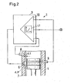
- the current thickness d of the lubricant film 7 is measured and the value of the drive unit 9, which in particular comprises a data processing system and control means 10, is supplied to a component of the reciprocating internal combustion engine which is adjacent to the cylinder 4. It is preferred, as in Fig. 2 schematically illustrated, a plurality of sensors 8 for measuring the thickness d of the lubricant film 7 is provided.
- the sensors 8 are passive structure-borne noise sensors, as may be determined by determining propagation time differences of the signals detected by the sensors 8 and / or using the known technique of correlating signals, ie examining the corresponding correlation function the signals, the thickness d of the lubricant film 7 are determined location-dependent.
- measuring means may be provided which determine various operating parameters B, such as, inter alia, the speed U, the load L or the cylinder temperature T of the reciprocating internal combustion engine and these also the drive means 9 perform.
- a look-up table LT is used, which is shown schematically in FIG Fig. 2a is shown.
- the lookup table LT is a two- or multi-dimensional data field, with the aid of, for example, from various relevant current and / or for the reciprocating internal combustion engine specific global operating parameters B and / or depending on the composition Z of the operating materials used, in particular the fuel or the lubricant used, and / or taking into account other relevant factors, a current setpoint for the state parameter ZP, here for the thickness d of the lubricant film 7 is determined.
- the setpoint determined in this way for example for the thickness d of the lubricant film 7, is compared with the characteristic value K determined by the sensor 8, that is to say the actual thickness d of the lubricant film 7, and related. From this, a signal for controlling the lubricant nozzle 6 is then generated with the aid of the control means 10, so that the lubricant nozzle 6 applies just enough lubricant to the running surface 2 of the cylinder wall 3 that the thickness d of the lubricant film 7 is optimized.
- various data relevant for the determination of an optimum value for the state parameter ZP, in the present example the optimum thickness d of the lubricant film 7, are stored.
- current operating parameters B such as, for example, rotational speed U and / or load L and / or cylinder temperature T and / or the temperature in the combustion chamber and / or other current operating parameters B are preferably determined using suitable devices which are already known for reciprocating internal combustion engines which, together with the data stored in the lookup table LT, the setpoint value for the optimum thickness d of the lubricant film 7 is then redefined again and again for each operating state.
- the resources used and their properties for example the fuel used, especially its sulfur content and / or the type of lubricant used and / or the BN value of the lubricant itself, for the optimum value of the state parameter ZP, ie
- Fig. 3 an induction sensor is shown, which is arranged according to the invention in a recess in a piston ring 51 of the piston 5 of the reciprocating internal combustion engine.
- the piston ring 51 is thereby suitably, in Fig. 3 Devices not shown so fixed in a groove of the piston 5 that no significant rotation of the piston ring 51 can take place in the operating state.
- the necessary for the operation of the sensor 8 electrical connection lines, for example, via a likewise not shown cable management system, which is preferably designed as a coupling gear, are guided out of the cylinder 4 to the outside.
- the configured as an induction sensor sensor 8 essentially comprises an example U-shaped magnetic core 81, which is preferably designed as a magnetic core 81 with high magnetic permeability, for example as a ferrite core 81, and which is surrounded by a coil 82.
- a magnetic flux is formed in the core 81, which is closed in a conventional manner via the lubricant film 7 and the cylinder wall 3.
- owned the closed circuit which essentially comprises the magnetic core 81, the lubricant film 7 with thickness d and the cylinder wall 3, a magnetic resistance, which results as the sum of the magnetic resistances of its aforementioned sections.
- the thickness d of the lubricant film 7 changes, the magnetic resistance caused by the lubricant film 7 inevitably changes, and thus the magnetic resistance and thus the inductance of the entire circuit changes.
- a change in the inductance of the circuit results in a change in the electric current through the coil 82 at a given electrical AC voltage U to the coil 82.
- a state parameter of the lubricant film on the running surface of the cylinder wall can be specifically optimized in the operating state of the reciprocating internal combustion engine.
- the state parameter can be represented by various characteristic characteristics of the lubricant film.
- the state parameter of the lubricant film that is optimized on the running surface of the cylinder wall is the thickness d of the lubricant film.
- the state parameter may also be the alkalinity, the temperature, the viscosity, the water content, the BN value or the acid content of the lubricant film, the list of the above examples for state parameters not being exhaustive.
- the amount of lubricant required for this purpose is preferably always determined currently taking into account various operating parameters, such as the speed, the combustion temperature, the engine temperature, the cooling power for cooling the engine, the load or other operating parameters.
- the invention is based on the essential knowledge that to achieve an optimum operating state of the reciprocating internal combustion engine, the state parameter, in particular in particular the thickness of the Schmierstofffims on the tread of the cylinder, preferably even locally, must be optimized. This means that what is primarily decisive is not the amount of lubricant supplied per se but the value of the condition parameter, in particular the actual thickness of the lubricant film on the running surface of the cylinder.
- the inventive not only the life of piston, piston rings and cylinder surface is significantly increased, but the lubricant consumption is also minimized simultaneously and the maintenance intervals are significantly extended.
Abstract
Description
Die Erfindung betrifft ein Verfahren sowie eine Vorrichtung zum Schmieren einer Lauffläche einer Zylinderwand eines Zylinders einer Hubkolbenbrennkraftmaschine, insbesondere eines langsam laufenden Grossdieselmotors gemäss dem Oberbegriff des unabhängigen Anspruchs der jeweiligen Kategorie.The invention relates to a method and a device for lubricating a running surface of a cylinder wall of a cylinder of a reciprocating internal combustion engine, in particular a slow-running large diesel engine according to the preamble of the independent claim of the respective category.
Grossdieselmotoren werden häufig als Antriebsaggregate für Schiffe oder auch im stationären Betrieb, z.B. zum Antrieb grosser Generatoren zur Erzeugung elektrischer Energie eingesetzt. Dabei laufen die Motoren in der Regel über beträchtliche Zeiträume im Dauerbetrieb, was hohe Anforderungen an die Betriebssicherheit und die Verfügbarkeit stellt. Daher sind für den Betreiber insbesondere lange Wartungsintervalle, geringer Verschleiss und ein wirtschaftlicher Umgang mit Brenn- und Betriebsstoffen zentrale Kriterien für den Betrieb der Maschinen. Unter anderem ist das Kolbenlaufverhalten solcher grossbohrigen langsam laufenden Dieselmotoren ein bestimmender Faktor für die Länge der Wartungsintervalle, die Verfügbarkeit und über den Schmiermittelverbrauch auch unmittelbar für die Betriebskosten und damit für die Wirtschaftlichkeit. Damit kommt der komplexen Problematik der Schmierung von Grossdieselmotoren eine immer grössere Bedeutung zu.Large diesel engines are often used as drive units for ships or in stationary operation, eg for driving large generators for generating electrical energy. The engines usually run for long periods in continuous operation, which places high demands on the reliability and availability. Therefore, for the operator in particular long maintenance intervals, low wear and an economical handling of fuels and supplies are central criteria for the operation of the machines. Among other things that is Piston running behavior of such large-bore slow-running diesel engines a determining factor for the length of the maintenance intervals, the availability and the lubricant consumption also directly for the operating costs and thus for the economy. Thus, the complex problem of lubrication of large diesel engines is becoming increasingly important.
Bei Grossdieselmotoren, jedoch nicht nur bei diesen, erfolgt die Kolbenschmierung durch Schmiereinrichtungen im sich hin und her bewegenden Kolben oder in der Zylinderwand, durch die Schmieröl auf die Lauffläche der Zylinderwand aufgebracht wird, um die Reibung zwischen Kolben und Lauffläche und damit die Abnützung der Lauffläche und der Kolbenringe zu minimieren. So liegt heute bei modernen Motoren, wie z.B. den Sulzer RTA-Motoren, die Abnutzung der Lauffläche bei weniger als 0.05 mm bei einer Betriebsdauer von 1000 Stunden. Die Schmiermittelfördermenge liegt bei solchen Motoren bei ca. 1.3 g/kWh und weniger und soll nicht zuletzt aus Kostengründen möglichst noch weiter reduziert werden, wobei gleichzeitig der Verschleiss minimiert werden soll.In large diesel engines, but not only these, the piston lubrication is performed by lubricating means in the reciprocating piston or in the cylinder wall, is applied by the lubricating oil on the tread of the cylinder wall, the friction between the piston and the tread and thus the wear of the tread and to minimize the piston rings. So today with modern engines, such as the Sulzer RTA engines, the tread wear at less than 0.05 mm with a service life of 1000 hours. The lubricant delivery rate is about 1.3 g / kWh and less in such engines and should not least be further reduced for cost reasons as possible, while the wear is to be minimized.
Als Schmiersysteme zur Schmierung der Laufflächen sind ganz verschiedene Lösungen bekannt, sowohl was die konkrete Ausführung der Schmiereinrichtungen selbst, als auch was die Verfahren zur Schmierung angeht. So sind Schmiereinrichtungen bekannt, bei denen das Schmieröl durch mehrere Schmiermittelöffnungen, die in Umfangsrichtung in der Zylinderwand untergebracht sind, auf den an der Schmiermittelöffnung vorbeilaufenden Kolben aufgebracht werden, wobei das Schmiermittel durch die Kolbenringe sowohl in Umfangsrichtung als auch in axialer Richtung verteilt wird. Dadurch, dass das Schmiermittel bei dieser Methode nicht grossflächig auf die Lauffläche der Zylinderwand, sondern mehr oder weniger punktuell zwischen die Kolbenringe auf die Seitenflächen des Kolbens aufgebracht wird, ist die Verteilung des Schmieröls auf der Lauffläche häufig nur ungenügend gewährleistet, was zu überhöhter Hitzeentwicklung infolge übermässiger Reibung und in letzter Konsequenz lokal zu einem Verschweissen der Kontaktflächen von Kolben und Lauffläche mit darauf folgendem Materialausbruch, also zu einem Kolbenfresser führen kann.As lubrication systems for lubricating the treads quite different solutions are known, both in terms of the actual execution of the lubrication devices themselves, as well as the procedures for lubrication. Thus, lubrication devices are known in which the lubricating oil is applied to the piston passing through the lubricant opening by a plurality of lubricant openings accommodated in the circumferential direction in the cylinder wall, wherein the lubricant is distributed by the piston rings both in the circumferential direction and in the axial direction. The fact that the lubricant is not applied over a large area on the running surface of the cylinder wall, but more or less selectively between the piston rings on the side surfaces of the piston in this method, the distribution of the lubricating oil on the tread is common only insufficiently ensured, which can lead to excessive heat development due to excessive friction and in the last consequence locally to a welding of the contact surfaces of the piston and tread with subsequent material outbreak, so to a piston seizure.
Um eine bessere Verteilung des Schmieröls, d.h. um einen gleichmässigeren Schmierölfilm auf der Lauffläche zu gewährleisten, wird beispielsweise in der
Bei einem anderen Verfahren sind im sich bewegenden Kolben bevorzugt mehrere Schmiermitteldüsen untergebracht, so dass das Schmiermittel im wesentliche über die gesamte Höhe der Lauffläche an beliebigen Stellen aufgebracht werden kann.In another method, preferably a plurality of lubricant nozzles are accommodated in the moving piston, so that the lubricant can essentially be applied anywhere over the entire height of the running surface.
Dabei ist neben der Art und Weise wie das Schmiermittel auf die Lauffläche der Zylinderwand aufgebracht wird auch die Dosierung des Schmiermittels ein zentraler Punkt. Die pro Zeit- und Flächeneinheit auf die Lauffläche aufzubringende Menge an Schmiermittel kann im Betrieb der Hubkolbenbrennkraftmaschine von vielen verschiedenen Parametern abhängig sein. So spielt beispielsweise die chemische Zusammensetzung des verwendeten Treibstoffs, insbesondere dessen Schwefelgehalt eine bedeutende Rolle. Neben der Schmierung des Zylinders, also der Herabsetzung der Reibung zwischen Kolben und Zylinderlauffläche, genauer zwischen den Kolbenringen und der Lauffläche der Zylinderwand, dient das Schmiermittel unter anderem auch zur Neutralisation aggressiver Säuren, insbesondere von schwefelhaltigen Säuren, die beim Verbrennungsvorgang im Brennraum des Motors entstehen. Daher können je nach verwendetem Treibstoff unterschiedliche Sorten von Schmiermittel zum Einsatz kommen, die sich unter anderem in ihrer Neutralisationsfähigkeit, für die der sogenannte BN-Wert des Schmiermittels ein Mass ist, unterscheiden. So kann es von Vorteil sein bei einem hohem Schwefelgehalt im Brennstoff ein Schmiermittel mit einem höheren BN-Wert zu verwenden, als bei einem Brennstoff mit einem niedrigeren Schwefelgehalt, weil ein Schmiermittel mit einem höheren BN-Wert eine stärkere Neutralisationswirkung gegenüber Säuren aufweist.In this case, in addition to the way in which the lubricant is applied to the running surface of the cylinder wall, the dosage of the lubricant is a central point. The quantity of lubricant to be applied to the running surface per unit of time and area may depend on many different parameters during operation of the reciprocating internal combustion engine. For example, the chemical composition of the fuel used, in particular its sulfur content plays an important role. In addition to the lubrication of the cylinder, so the reduction of the friction between the piston and cylinder surface, more precisely between the piston rings and the tread of the cylinder wall, the lubricant is used, inter alia, for the neutralization of aggressive acids, especially sulfur-containing acids that arise during the combustion process in the combustion chamber of the engine , Therefore, depending on the fuel used different grades of lubricant can be used, which differ, inter alia, in their neutralization ability, for which the so-called BN value of the lubricant is a measure. Thus, for a high sulfur content in the fuel, it may be advantageous to use a lubricant with a higher BN value than a fuel with a lower sulfur content, because a lubricant with a higher BN value has a stronger acid neutralization effect.
Oft ist es jedoch auch möglich, dass für Treibstoffe unterschiedlicher Qualität die gleiche Schmiermittelsorte verwendet werden muss. In solchen Fällen kann dann beispielsweise durch entsprechende Erhöhung oder Erniedrigung der eingesetzten Menge an Schmiermittel ein höherer oder niedrigerer Säuregehalt in den Verbrennungsprodukten kompensiert werden.Often, however, it is also possible that the same type of lubricant must be used for fuels of different quality. In such cases, for example, by a corresponding increase or decrease in the amount of lubricant used, a higher or lower acid content in the combustion products can be compensated.
Ein weiteres Problem bei der Dosierung der aufzutragenden Schmiermittelmenge stellen zeitliche und / oder örtliche Schwankungen des Zustands des Schmiermittelfilms, insbesondere der Dicke des Schmiermittelfilms im Betriebszustand der Hubkolbenbrennkraftmaschine dar.Another problem in the metering of the amount of lubricant to be applied are temporal and / or local variations in the state of the lubricant film, in particular the thickness of the lubricant film in the operating state of the reciprocating internal combustion engine.
Selbstverständlich kann die notwendige Menge an Schmiermittel beispielsweise auch von unterschiedlichsten Betriebsparametern, wie der Drehzahl, der Verbrennungstemperatur, der Motortemperatur, der Kühlleistung zur Kühlung des Motors, der Last und vielen anderen Betriebsparametern mehr abhängig. So kann es möglich sein, dass bei gegebener Drehzahl und höherer Last eine andere Menge an Schmiermittel auf die Lauffläche des Zylinders aufgebracht werden muss, als bei gleicher Drehzahl und niedrigerer Last.Of course, the necessary amount of lubricant, for example, from a variety of operating parameters, such as the speed, the combustion temperature, the engine temperature, the cooling power for cooling the engine, the load and many other operating parameters more dependent. So it may be possible that at a given speed and higher load a different amount of lubricant must be applied to the tread of the cylinder, as with the same speed and lower load.
Des weiteren kann auch der Zustand der Verbrennungsmaschine an sich einen Einfluss auf die Schmiermittelmenge haben. So ist es beispielsweise bekannt, dass je nach Verschleisszustand von Zylinderlauffläche, Kolbenringen, Kolben und so weiter die einzusetzende Schmiermittelmenge stark variieren kann. So ist bei einem Zylinder mit einer neuen, noch nicht eingefahren Zylinderlauffläche und / oder bei neuen Kolbenringen in der Einlaufphase eine erhöhte Reibung in gewissem Umfang durchaus erwünscht, damit sich die Gegenlaufpartner, also z.B. Kolbenringe und Lauffläche, einschleifen und so optimal aufeinander einstellen können. Das kann unter anderem dadurch erreicht werden, dass in der Einlaufphase eines Zylinders pauschal mit einer anderen Schmiermittelmenge gearbeitet wird, als bei einem Zylinder, der bereits eine beachtliche Zahl von Betriebsstunden in Betrieb ist. Daher ist bei einer Maschine mit mehreren Zylindern die Schmiermittelmenge insbesondere für jeden Zylinder häufig separat einstellbar.Furthermore, the state of the internal combustion engine itself can have an influence on the amount of lubricant. For example, it is known that, depending on the state of wear of the cylinder surface, piston rings, pistons and so on, the amount of lubricant to be used can vary greatly. Thus, in a cylinder with a new, not yet retracted cylinder tread and / or new piston rings in the break-in phase, increased friction is to some extent quite desirable in order for the mating partners, e.g. Piston rings and tread, grind in and can optimally adjust to each other. Among other things, this can be achieved by using a different amount of lubricant in the running-in phase of a cylinder than in the case of a cylinder which is already in operation for a considerable number of operating hours. Therefore, in a multi-cylinder engine, the amount of lubricant is often separately adjustable, particularly for each cylinder.
Auch wird im allgemeinen die Zylinderlauffläche sowohl in Umfangsrichtung als auch in Längsrichtung in Abhängigkeit von der Zahl der geleisteten Betriebsstunden unterschiedlich verschleissen. Das gilt analog beispielsweise auch für die Kolbenringe und die Kolben selbst.Also, in general, the cylinder running surface will wear differently both in the circumferential direction and in the longitudinal direction depending on the number of operating hours performed. This applies analogously, for example, for the piston rings and the piston itself.
Somit muss die Schmiermittelmenge bei einer Hubkolbenbrennkraftmaschine nicht nur in Abhängigkeit von der Zahl der geleisteten Betriebsstunden eingestellt werden, sondern die Schmiermittelmenge sollte auch innerhalb ein und desselben Zylinders an unterschiedlichen Stellen der Lauffläche der Zylinderwand je nach Anforderungen zeitabhängig und örtlich verschieden dosierbar sein.Thus, the amount of lubricant in a reciprocating internal combustion engine must not only be adjusted depending on the number of hours worked, but the amount of lubricant should be metered depending on the time and depending on different localities within one and the same cylinder at different points of the tread of the cylinder wall.
Daher ist es seit langem bekannt in einer Lauffläche eines Zylinders oder im sich bewegenden Kolben in unterschiedlichen Bereichen Schmiermitteldüsen vorzusehen, die bevorzugt alle einzeln ansteuerbar sind, so dass die Schmiermittelmenge je nach Anforderung sowohl zeitlich als auch örtlich flexibel variiert werden kann.Therefore, it has long been known to provide in a running surface of a cylinder or in the moving piston in different areas lubricant nozzles, which are preferably all individually controlled, so that the amount of lubricant can be varied depending on the requirements both temporally and locally flexible.
Um die von einer bestimmten Schmiermitteldüse zu einem bestimmten Zeitpunkt einzubringende Menge an Schmiermittel zu ermitteln sind verschiedene Verfahren bekannt. In einfachen Fällen wird die Schmiermittelmenge, eventuell unter Berücksichtigung der Qualität des verwendeten Treibstoffs und des Schmiermittels selbst, einfach in Abhängigkeit vom Betriebszustand der Hubkolbenbrennkraftmaschine gesteuert, zum Beispiel als Funktion der Last oder der Drehzahl, wobei aufgrund von bereits geleisteten Betriebsstunden auch der Verschleisszustand der Gegenlaufpartner Berücksichtigung finden kann.In order to determine the amount of lubricant to be introduced by a particular lubricant nozzle at a particular time, various methods are known. In simple cases, the amount of lubricant, possibly taking into account the quality of the fuel used and the lubricant itself, simply controlled depending on the operating state of the reciprocating internal combustion engine, for example as a function of load or speed, due to already performed operating hours and the state of wear of the mating partner Can be considered.
Dabei sind durchaus auch differenziertere Methoden zur Regulierung der Schmiermittelmenge bekannt. So wird beispielsweise in der
Allen diesen Vorrichtungen und Verfahren ist jedoch gemeinsam, dass der Ort des Auftretens von Verschleisserscheinungen, wie beginnendes Fressen der Kolbenringe oder das wohlbekannte Scuffing, in der Lauffläche der Zylinderwand nur ungenügend genau oder gar nicht lokalisierbar sind. Das heisst, mit den aus dem Stand der Technik bekannten Verfahren und Vorrichtungen ist zwar das Auftreten abnormaler Betriebszustände der Hubkolbenbrennkraftmaschine grundsätzlich feststellbar, jedoch können deren Ursachen nicht am Ort der Entstehung bekämpft werden, da mit den bekannten Methoden und Vorrichtungen der Ort der Entstehung im Zylinder nicht mit der notwendigen Ortsauflösung detektierbar ist. Was letztlich unter anderem bedeutet, dass die Dicke des Schmiermittelfilms bestenfalls ganz in der Nähe eventuell vorhandenen Sensoren, beispielsweise in der Nähe der oben erwähnten Ultraschallsensoren, zuverlässig bestimmt werden kann. Der Zustand des Schmiermittelfilms in seiner gesamten Ausdehnung über die Lauffläche der Zylinderwand ist dagegen nicht kontrollierbar.However, all these devices and methods have in common that the location of the occurrence of signs of wear, such as incipient seizure of the piston rings or the well-known scuffing, in the tread of the cylinder wall are insufficiently accurate or impossible to localize. That is, with the methods and devices known from the prior art, although the occurrence of abnormal operating conditions of the reciprocating internal combustion engine is basically detectable, but their causes can not be combated at the place of origin, since with the known methods and devices, the place of origin in the cylinder not detectable with the necessary spatial resolution. This means, among other things, that the thickness of the lubricant film can at best be reliably determined in the vicinity of possibly existing sensors, for example in the vicinity of the abovementioned ultrasonic sensors. The state of the lubricant film in its entire extent over the running surface of the cylinder wall, however, is not controllable.
Wird beispielsweise bei einer aus dem Stand der Technik bekannten Vorrichtung in einem bestimmten Zylinder das Auftreten von Kolbenfressen oder Scuffing detektiert, so wird für diesen Zylinder die Schmiermittelmenge so lange erhöht, bis der detektierte abnormale Betriebszustand wieder verschwindet und die diesem Zylinder pro Zeiteinheit zugeführte Schmiermittelmenge wieder reduziert werden kann.If, for example, the occurrence of piston seizure or scuffing is detected in a device known from the prior art, then the lubricant quantity is increased for this cylinder until the detected abnormal operating state disappears again and the quantity of lubricant supplied to this cylinder per unit time again can be reduced.
So unterscheidet der Fachmann den Bereich der sogenannten hydrodynamischen Schmierung, vom Zustand der Mangelschmierung und der Mischschmierung. Von hydrodynamischer Schmierung spricht man, wenn sich zwischen den Gegenlaufpartnem, also zum Beispiel zwischen der Lauffläche einer Zylinderwand und dem Kolbenring eines Kolbens ein Schmiermittelfilm von solcher Dicke ausgebildet ist, dass die Oberflächen der Gegenlaufpartner durch den Schmiermittelfilm voneinander wohlgetrennt sind, so dass diese sich nicht berühren. Einen anderen Grenzfall stellt der sogenannte Zustand der Mischreibung oder Mischschmierung dar. Im Falle der Mischreibung ist der Schmiermittelfilm zwischen den Gegenlaufpartner, zumindest teilweise, so dünn, dass sich die Gegenlaufpartner unmittelbar berühren. In diesem Fall besteht die Gefahr von Scuffing und letztlich der Ausbildung eines Kolbenfressers. Zwischen diesen beiden Grenzfällen ist die sogenannte Mangelschmierung angesiedelt. Im Zustand der Mangelschmierung ist der Schmiermittelfilm gerade noch so dick, dass sich die Gegenlaufpartner nicht mehr berühren; die Schmiermittelmenge zwischen den Gegenlaufpartnern reicht jedoch nicht aus, dass sich eine hydrodynamische Schmierung aufbauen könnte. Im Stand der Technik wird sowohl der Zustand der Mischschmierung, als auch der Mangelschmierung möglichst verhindert. Das heisst, die Dicke des Schmiermittelfilms wird bevorzugt so gewählt, dass sich ein Zustand der hydrodynamischen Schmierung zwischen den Gegenlaufpartnern einstellt.Thus, the expert distinguishes the field of so-called hydrodynamic lubrication, the state of lack lubrication and the mixed lubrication. Hydrodynamic lubrication is when a lubricant film of such thickness is formed between the Gegenlaufpartnem, so for example between the running surface of a cylinder wall and the piston ring of a piston, that the surfaces of the mating partner are well separated by the lubricant film from each other so that they are not touch. Another limiting case is the so-called mixed friction or mixed lubrication condition. In the case of mixed friction, the lubricant film between the mating partners is, at least in part, so thin that the mating partners touch each other directly. In this case, there is a risk of scuffing and ultimately the training of a piston eater. Between these two borderline cases the so-called lack lubrication is settled. In the state of deficient lubrication, the lubricant film is just so thick that the counterpart partners no longer touch; However, the amount of lubricant between the mating partners is not enough that a hydrodynamic lubrication could build up. In the prior art, both the state of the mixed lubrication, and the lack of lubrication is possible prevented. That is, the thickness of the lubricant film is preferably selected so as to establish a state of hydrodynamic lubrication between the mating partners.
Der Betrieb im Bereich der hydrodynamischen Schmierung hat natürlich einen entsprechend hohen Schmiermittelverbrauch zur Folge. Das ist einerseits nicht nur ausgesprochen unwirtschaftlich, sondern es hat sich überraschenderweise auch gezeigt, dass nicht nur ein Schmiermittelmangel, sondern auch ein Schmiermittelüberschuss zu Schädigungen der Gegenlaufpartner im Zylinder führen kann.The operation in the field of hydrodynamic lubrication naturally results in a correspondingly high lubricant consumption. On the one hand, this is not only extremely uneconomical, but it has also surprisingly been found that not only a lack of lubricant, but also an excess of lubricant can lead to damage of the mating partner in the cylinder.
Die Aufgabe der Erfindung ist es daher, ein verbessertes Verfahren und eine verbesserte Vorrichtung zum Schmieren einer Hubkolbenbrennkraftmaschine vorzuschlagen.The object of the invention is therefore to propose an improved method and an improved apparatus for lubricating a reciprocating internal combustion engine.
Die diese Aufgaben in verfahrenstechnischer und apparativer Hinsicht lösenden Gegenstände der Erfindung sind durch die Merkmale des unabhängigen Anspruchs der jeweiligen Kategorie gekennzeichnet.The objects of the invention which solve these objects in terms of process and apparatus are characterized by the features of the independent claim of the respective category.
Die jeweiligen abhängigen Ansprüche beziehen sich auf besonders vorteilhafte Ausführungsformen der Erfindung.The respective dependent claims relate to particularly advantageous embodiments of the invention.
Die Erfindung betrifft somit ein Verfahren zum Schmieren einer Lauffläche einer Zylinderwand eines Zylinders einer Hubkolbenbrennkraftmaschine, insbesondere eines langsam laufenden Grossdieselmotors, in welchem Zylinder ein Kolben entlang der Lauffläche hin- und herbewegbar angeordnet ist. Bei dem Verfahren wird mittels einer Schmiermitteldüse ein Schmiermittelfilm auf die Lauffläche der Zylinderwand aufgebracht und mittels eines Sensors eine für den Schmiermittelfilm charakteristische Kenngrösse bestimmt. Dabei wird der Sensor erfindungsgemäss in einem Kolbenring vorgesehen und es wird mit einer Ansteuereinheit, die Regelmittel umfasst, mit Hilfe eines Signals des Sensors die Schmiermitteldüse derart angesteuert, dass ein Zustandsparameter des Schmiermittelfilms auf der Lauffläche der Zylinderwand optimiert wird.The invention thus relates to a method for lubricating a running surface of a cylinder wall of a cylinder of a reciprocating internal combustion engine, in particular a slow-running large diesel engine, in which cylinder a piston along the tread is arranged back and forth. In the method, a lubricant film is applied to the running surface of the cylinder wall by means of a lubricant nozzle and determined by means of a sensor characteristic of the lubricant film characteristic. According to the invention, the sensor is provided in a piston ring and, with the aid of a signal from the sensor, the lubricant nozzle is controlled by a control unit such that a state parameter of the lubricant film on the running surface of the cylinder wall is optimized.
Der Erfindung liegt die wesentliche Erkenntnis zugrunde, dass zum Erreichen eines optimalen Betriebszustands der Hubkolbenbrennkraftmaschine ein Zustandsparameter, zum Beispiel die Dicke des Schmiermittelfilms auf der Lauffläche des Zylinders, bevorzugt sogar lokal, optimiert werden muss. Das heisst, primär entscheidend ist nicht die zugeführte Menge an Schmiermittel als solches, sondern ein aktueller Wert des Zustandsparameters, zum Beispiel die aktuelle Dicke des Schmiermittelfilms auf der Lauffläche des Zylinders, wobei ein Sollwert für den Zustandsparameter unter anderem noch vom Betriebszustand der Brennkraftmaschine, den Eigenschaften der verwendeten Betriebsmittel usw. abhängen kann.The invention is based on the essential knowledge that in order to achieve an optimum operating state of the reciprocating internal combustion engine, a state parameter, for example the thickness of the lubricant film on the running surface of the cylinder, preferably even locally, must be optimized. This means that what is primarily decisive is not the amount of lubricant supplied per se, but a current value of the state parameter, for example the actual thickness of the lubricant film on the running surface of the cylinder, wherein a desired value for the state parameter inter alia still depends on the operating state of the internal combustion engine Properties of the equipment used.
Bevorzugt, jedoch nicht notwendig, wird die Schmiermittelmenge auf der Lauffläche der Zylinderwand so eingestellt, dass sich eine Dicke des Schmiermittelfilms ausbildet, so dass im wesentlichen der Zustand der Mangelschmierung erreicht wird. Im Zustand der Mangelschmierung ist der Schmiermittelfilm so ausgebildet, dass sich die Gegenlaufpartner nicht mehr berühren, wobei die Schmiermittelmenge zwischen den Gegenlaufpartnern nicht ausreicht, um eine hydrodynamische Schmierung zwischen den Gegenlaufpartner aufzubauen.Preferably, but not necessarily, the amount of lubricant on the running surface of the cylinder wall is adjusted so that a thickness of the lubricant film is formed, so that substantially the state of the deficiency lubrication is achieved. In the state of deficient lubrication of the lubricant film is formed so that the mating partner no longer touch, the amount of lubricant between the mating partners is not sufficient to build a hydrodynamic lubrication between the mating partner.
Daher umfasst die Vorrichtung zur Durchführung des erfindungsgemässen Verfahrens einen geeigneten Sensor, der die Messung einer charakteristischen Kenngrösse des Schmiermittelfilms auf der Lauffläche der Zylinderwand gestattet, so dass mit Hilfe einer Ansteuereinheit die Schmiermitteldüse derart angesteuert wird, dass der Zustandsparameter des Schmiermittelfilms, insbesondere die Dicke des Schmiermittelfilms auf der Lauffläche optimiert wird.Therefore, the device for carrying out the method according to the invention comprises a suitable sensor which allows the measurement of a characteristic parameter of the lubricant film on the running surface of the cylinder wall, so that the lubricant nozzle is controlled with the aid of a drive unit in such a way that the condition parameter of the lubricant film, in particular the thickness of the lubricant film Lubricant film on the tread is optimized.
Dabei kann der Zustand des Schmiermittelfilms auf der Lauffläche der Zylinderwand durch unterschiedliche Parameter bestimmt sein. So kann die charakteristische Kenngrösse unter anderem die Dicke des Schmiermittelfilms und / oder die Alkalinität und / oder die Temperatur und / oder die Viskosität und / oder der Wassergehalt und / oder der Säuregehalt des Schmiermittelfilms sein und somit den Ist-Zustand des Schmiermittelfilms bestimmen. Daher kann durch Messung von einer oder mehrerer dieser charakteristischen Kenngrössen der Zustand des Schmiermittelfilms auf der Lauffläche der Zylinderwand bestimmt werden.In this case, the state of the lubricant film on the running surface of the cylinder wall can be determined by different parameters. Thus, the characteristic characteristic may be, inter alia, the thickness of the lubricant film and / or the alkalinity and / or the temperature and / or the viscosity and / or the water content and / or the acid content of the lubricant film and thus the actual state of the lubricant film determine. Therefore, by measuring one or more of these characteristic characteristics, the state of the lubricant film on the running surface of the cylinder wall can be determined.
Während bei den aus dem Stand der Technik bekannten Verfahren die zugeführte Schmiermittelmenge beim Auftreten von erhöhter Reibung zwischen den Gegenlaufpartnern im Zylinder, z.B. beim Auftreten von Scuffing, zur Verbesserung der Reibeigenschaften einfach erhöht wird, wird bei dem erfindungsgemässen Verfahren die Zufuhr durch die Schmiermitteldüse derart gesteuert und / oder geregelt, dass sich ein optimaler Wert des Zustandsparameters, z.B. eine optimale Dicke des Schmiermittelfilms einstellt, wodurch die tribologischen Laufeigenschaften optimiert werden. Selbstverständlich kann der Zustandsparameter ausser der Dicke des Schmiermittelfilms auch die Alkalinität und / oder die Temperatur und / oder die Viskosität und / oder der Wassergehalt und / oder der Säuregehalt des Schmiermittelfilms sein. Daher ist es möglich dass entweder nur einer dieser Zustandsparameter optimiert wird, oder zwei oder mehrere dieser Zustandsparameter gleichzeitig optimiert wird.While in the methods known from the prior art, the amount of lubricant supplied on the occurrence of increased friction between the counterpart partners in the cylinder, e.g. in the process of the present invention, the supply through the lubricant nozzle is controlled and / or regulated such that an optimum value of the condition parameter, e.g. an optimal thickness of the lubricant film is adjusted, whereby the tribological running properties are optimized. Of course, besides the thickness of the lubricant film, the state parameter may also be the alkalinity and / or the temperature and / or the viscosity and / or the water content and / or the acid content of the lubricant film. Therefore, it is possible that either only one of these state parameters is optimized, or two or more of these state parameters are simultaneously optimized.
Insbesondere ist weder die Liste der zuvor genannten Kenngrössen noch die Liste der genannten Zustandsparameter abschliessend zu verstehen. Auch andere Eigenschaften des Schmiermittelfilms können vorteilhaft als charakteristische Kenngrössen des Schmiermittelfilms herangezogen werden und entsprechend als Zustandsparameter optimiert werden. Es versteht sich darüber hinaus, dass zur Optimierung eines bestimmten Zustandsparameters, zum Beispiel zur Optimierung der Dicke des Schmiermittelfilms auf der Lauffläche der Zylinderwand, unter Heranziehung jeder geeigneten Kenngrösse erfolgen kann. So kann es beispielsweise je nach Anwedung vorteilhaft sein, als charakteristische Kenngrösse die Alkalinität des Schmiermittelfilms zu bestimmen und mit Hilfe dieser Information die Schmiermitteldüse derart anzusteuern, dass eine andere Zustandsgrösse als die Alkalinität des Schmiermittelfilms, zum Beispiel die Dicke des Schmiermittelfilms optimiert.In particular, neither the list of the aforementioned parameters nor the list of the mentioned condition parameters is to be understood conclusively. Other properties of the lubricant film can advantageously be used as characteristic parameters of the lubricant film and be optimized accordingly as a state parameter. It goes without saying that in order to optimize a specific state parameter, for example to optimize the thickness of the lubricant film on the running surface of the cylinder wall, it is possible to use any suitable parameter. Thus, depending on the application, it may be advantageous, for example, to determine the alkalinity of the lubricant film as the characteristic parameter and to control the lubricant nozzle with the aid of this information in such a way that a different state variable than the alkalinity of the lubricant film, for example, the thickness of the lubricant film is optimized.
Da sich, wie bereits oben erwähnt, auch eine zu grosse Menge an Schmiermittel auf der Lauffläche der Zylinderwand deutlich negativ auf die Reibung zwischen den Gegenlaufpartnern im Zylinder auswirken kann, können die aus dem Stand der Technik bekannten Verfahren, die bei sich erhöhender oder erhöhter Reibung im Zylinder ohne Rücksicht z.B. auf die tatsächliche Dicke des Schmiermittelfilms die Schmiermittelmenge immer weiter erhöhen, letztlich schwere Schäden bis hin zum Kolbenfresser im Zylinder der Hubkolbenbrennkraftmaschine verursachen.Since, as already mentioned above, an excessively large amount of lubricant on the running surface of the cylinder wall can have a markedly negative effect on the friction between the counterpart partners in the cylinder, the methods known from the prior art can increase or increase the friction in the cylinder without consideration eg on the actual thickness of the lubricant film, the amount of lubricant continues to increase, ultimately causing severe damage to the piston eater in the cylinder of the reciprocating internal combustion engine.
Das erfindungsgemässe Verfahren berücksichtigt dagegen eine oder mehrere der charakteristischen Kenngrössen, wie zum Beispiel die tatsächliche Dicke des Schmiermittelfilms und regelt durch Steuerung der Schmiermittelzufuhr einen oder mehrere Zustandsparameter, z.B. die optimale Dicke des Schmiermittelfilms ein. Das heisst, wenn eine erhöhte Reibung zwischen den Gegenlaufpartnern im Zylinder beispielsweise durch eine zu hohe Schmiermittelmenge auf der Lauffläche des Zylinders verursacht ist, wird bei dem erfindungsgemässen Verfahren die Schmiermittelmenge nicht automatisch erhöht, sondern soweit reduziert, dass sich wieder zum Beispiel eine optimale Dicke des Schmiermittelfilms auf der Lauffläche des Zylinders einstellt.By contrast, the method according to the invention takes account of one or more of the characteristic parameters, such as the actual thickness of the lubricant film, and regulates one or more state parameters, e.g. the optimum thickness of the lubricant film. That is, if an increased friction between the mating partners in the cylinder is caused for example by an excessive amount of lubricant on the running surface of the cylinder, the amount of lubricant is not automatically increased in the inventive method, but reduced so much that, for example, an optimum thickness of the Lubricant film on the tread of the cylinder adjusts.
Dadurch werden nicht nur Fehlsteuerungen bei der Schmiermittelzufuhr der zuvor beschrieben Art verhindert, sondern der Schmiermittelverbrauch wird darüber hinaus automatisch bei gleichzeitiger Optimierung der Laufeigenschaften, minimiert.This not only prevents mal-control in the lubricant supply of the type described above, but the lubricant consumption is also automatically minimized while optimizing the running properties.
Bevorzugt wird dabei der Zustandsparameter, insbesondere die Dicke des Schmiermittelfilms lokal optimiert. Dazu können, zum Beispiel in der Zylinderwand oder im Kolben der Hubkolbenbrennkraftmaschine, eine oder mehrere Schmiermitteldüsen vorgesehen sein, die entweder einzeln oder in Gruppen durch die Ansteuereinheit angesteuert werden und vorteilhaft an verschiedenen Positionen sowohl in Umfangsrichtung als auch in axialer Richtung über die Zylinderwand oder den Kolben verteilt sein können. Insbesondere können mehrere Sensoren so betrieben werden und an geeigneten Stellen derart positioniert sein, dass die Dicke des Schmiermittelfilms mit genügend grosser Ortsauflösung bestimmt wird, so dass zum Beispiel die Dicke des Schmiermittelfilms auf der Lauffläche der Zylinderwand lokal optimiert werden kann. Somit kann insbesondere in ein und demselben Zylinder an einem und / oder verschiedenen Orten der Lauffläche zur gleichen Zeit und / oder zu verschiedenen Zeiten durch zwei verschiedene Schmiermitteldüsen jeweils eine unterschiedliche Menge an Schmiermittel zugeführt werden, so dass unabhängig voneinander an beiden Orten auf der Lauffläche der Zylinderwand die Dicke des Schmiermittelfilms, oder ein anderer Zustandsparameter optimiert wird. Insbesondere kann durch geeignete Wahl des Zeitpunktes der Schmiermittelzufuhr das Schmiermittel beispielsweise in Laufrichtung des Kolbens auf der Lauffläche des Zylinders besser verteilt werden, indem das Schmiermittel kurz bevor der Kolben eine bestimmte Schmiermitteldüse passiert, durch diese bestimmte Schmiermitteldüse zugeführt wird. Das heisst, je nach Bewegung des Kolbens in Richtung zum oberen Totpunkt oder davon weg ist so das Schmiermittel auf der Lauffläche des Zylinders in der jeweiligen Richtung optimal verteilbar.Preferably, the state parameter, in particular the thickness of the lubricant film is locally optimized. For this purpose, for example in the cylinder wall or in the piston of the reciprocating internal combustion engine, one or more lubricant nozzles may be provided, which are controlled either individually or in groups by the drive unit and advantageous at different positions both in the circumferential direction and in the axial direction over the cylinder wall or the Pistons can be distributed. In particular, a plurality of sensors can be operated and positioned at suitable locations such that the thickness of the lubricant film is determined with a sufficiently large spatial resolution, so that, for example, the thickness of the lubricant film on the running surface of the cylinder wall can be locally optimized. Thus, in particular in the same cylinder at one and / or different locations of the tread at the same time and / or at different times by two different lubricant nozzles each have a different amount of lubricant are supplied, so that independently of each other at both locations on the tread Cylinder wall, the thickness of the lubricant film, or another state parameter is optimized. In particular, by suitable choice of the time of lubricant supply, the lubricant can be better distributed, for example in the direction of the piston on the tread of the cylinder by the lubricant just before the piston passes a certain lubricant nozzle, is fed through this particular lubricant nozzle. That is, depending on the movement of the piston in the direction of the top dead center or away from it so the lubricant on the tread of the cylinder in the respective direction optimally distributed.
Dabei wird bei einer besonders bevorzugten Ausführungsvariante des erfindungsgemässen Verfahrens ein Sollwert für die Dicke des Schmiermittelfilms in Abhängigkeit von verschiedenen Betriebsparametern der Hubkolbenbrennkraftmaschine, insbesondere in Abhängigkeit von der Drehzahl und / oder der Last und / oder der Zylindertemperatur und / oder anderen Betriebsparametern und / oder in Abhängigkeit von der Zusammensetzung eines Brennstoffs und / oder des Schmiermittels und /oder anderer Betriebsstoffe, mit Hilfe einer Lookup-Table, die in Form eines mehrdimensionalen Datenfeldes vorliegen kann, bestimmt, und die Dicke des Schmiermittelfilms auf den Sollwert optimiert.In this case, in a particularly preferred embodiment of the inventive method, a desired value for the thickness of the lubricant film in dependence on various operating parameters of the reciprocating internal combustion engine, in particular in dependence on the speed and / or load and / or the cylinder temperature and / or other operating parameters and / or depending on the composition of a fuel and / or the lubricant and / or other operating materials, using a lookup table, which may be in the form of a multi-dimensional data field determined, and the thickness of the lubricant film is optimized to the desired value ,
In der Lookup-Table, die beispielsweise als Datenbank in eine Datenverarbeitungsanlage, die Teil der Ansteuereinheit sein kann, geladen wird, sind wichtige, für die Ermittlung der optimalen Dicke des Schmierfilms relevante Daten gespeichert. Bevorzugt werden mit geeigneten Einrichtungen, die im wesentlichen für Hubkolbenbrennkraftmaschinen bereits bekannt sind, zusätzlich aktuelle Betriebsparameter wie beispielsweise Drehzahl und / oder Last und / oder die Zylindertemperatur und / oder die Temperatur im Brennraum und / oder andere aktuelle Betriebsparameter bestimmt, aus denen dann zusammen mit den in der Lookup-Table hinterlegten Daten der Sollwert für den Zustandsparameter, z.B. der Sollwert für die Dicke des Schmiermittelfilms für jeden Betriebszustand bestimmt wird. Da insbesondere unter anderem auch die verwendeten Betriebsmittel und deren Eigenschaften, zum Beispiel der verwendete Treibstoff, vor allem dessen Schwefelgehalt und / oder die Art des verwendeten Schmiermittels und / oder der BN-Wert des Schmiermittels, für den optimalen Wert des Zustandsparameters eine zentrale Rolle spielen, können auch diese zur Ermittlung des Sollwerts vorteilhaft herangezogen und im Betrieb durch geeignete Messeinrichtung ständig überwacht werden.In the look-up table, which is loaded, for example, as a database into a data processing system which may be part of the drive unit, important data relevant for determining the optimum thickness of the lubricant film are stored. In addition, with suitable devices, which are already known essentially for reciprocating internal combustion engines, additional current operating parameters such as speed and / or load and / or the cylinder temperature and / or the temperature in the combustion chamber and / or other current operating parameters are determined, from which then together with the data stored in the lookup table, the setpoint for the state parameter, eg the target value for the thickness of the lubricant film is determined for each operating condition. In particular, among other things, the resources used and their properties, for example the fuel used, especially its sulfur content and / or the type of lubricant used and / or the BN value of the lubricant, play a central role for the optimum value of the condition parameter , These can also be used to determine the desired value advantageous and constantly monitored during operation by suitable measuring device.
Es versteht sich, dass die oben genannte Aufzählung von Parametern und /oder Daten des Betriebszustands der Hubkolbenbrennkraftmaschine, die zur Ermittlung des Sollwerts des Zustandsparameters vorteilhaft herangezogen werden können, nicht abschliessend ist, sondern auch weitere für die Bestimmung des Sollwerts relevante Parameter und Daten enthalten kann.It is understood that the abovementioned enumeration of parameters and / or data of the operating state of the reciprocating internal combustion engine, which can be advantageously used to determine the setpoint value of the state parameter, is not exhaustive, but may also include further parameters and data relevant for the determination of the setpoint value ,
Die Vorrichtung zur Durchführung des erfindungsgemässen Verfahrens weist dabei, wie bereits erwähnt, mindestens eine in der Zylinderwand und / oder im Kolben angeordnete Schmiermitteldüse zum Aufbringen des Schmiermittelfilms auf die Lauffäche der Zylinderwand auf, sowie mindestens einen in einem Kolbenring vorgesehenen Sensor zur Messung der Dicke des Schmiermittelfilms, wobei eine Ansteuereinheit für die Schmiermitteldüse vorgesehen ist und die Ansteuereinheit Regelmittel umfasst, welche mit Hilfe eines Signals des Sensors die Schmiermitteldüse derart ansteuert, dass die Dicke des Schmiermittelfilms auf der Lauffläche der Zylinderwand optimiert ist.The device for carrying out the method according to the invention has, as already mentioned, at least one lubricant nozzle arranged in the cylinder wall and / or in the piston for applying the lubricant film to the running surface of the cylinder wall, and at least one sensor provided in a piston ring for measuring the thickness of the cylinder Lubricating film, wherein a drive unit for the lubricant nozzle is provided and the drive unit comprises control means which, with the aid of a signal of the sensor, the lubricant nozzle controls such that the thickness of the lubricant film is optimized on the running surface of the cylinder wall.
Dabei können weitere Sensoren vorteilhaft an unterschiedlichen Stellen im Zylinder angeordnet werden, wobei die Anordnung des Sensors unter anderem von der Art des Sensors abhängen kann, jedoch nicht davon abhängen muss.In this case, further sensors can advantageously be arranged at different locations in the cylinder, wherein the arrangement of the sensor may depend, inter alia, on the type of sensor, but does not have to depend on it.
Bevorzugt wird bei der Messung der Dicke des Schmiermittelfilms auf der Lauffläche der Zylinderwand des Zylinders eine genügend hohe Ortsauflösung angestrebt. Dazu können verschiedene Massnahmen geeignet eingesetzt werden.Preferably, in the measurement of the thickness of the lubricant film on the running surface of the cylinder wall of the cylinder a sufficiently high spatial resolution is desired. Various measures can be suitably used for this purpose.
Erfindungsgemäss ist der Sensor in einem Kolbenring angeordnet. Diese Anordnung ist besonders dann vorteilhaft einsetzbar, wenn ein Sensor zum Einsatz kommt, der im wesentlichen nur eine lokal eng begrenzte Messung zulässt. Solche Sensoren können zum Beispiel Ultraschallwandler sein, die die Dicke des Schmiermittelfilms aus einem Ultraschallecho bestimmen oder kapazitive, induktive Sensoren, Wirbelstromsensoren oder Widerstandssensoren, die die Dicke des Schmiermittelfilms aus einer entsprechenden Kapazitäts-, Induktivitäts oder Widerstandsänderung bestimmen. Selbstverständlich können auch andere Typen von Sensoren, wie zum Beispiel Temperatursensoren vorgesehen sein. Dabei können im Kolbenring nicht nur lokal wirkende Sensoren vorteilhaft Verwendung finden, sondern auch solche, die beispielsweise durch Zusammenwirken mit anderen Sensoren grosssflächige Messungen der Dicke des Schmiermittelfilms erlauben. Insbesondere kann die Kombination verschiedener Sensortypen in speziellen Fällen von Vorteil sein.According to the invention, the sensor is arranged in a piston ring. This arrangement is particularly advantageous when a sensor is used, which allows only a locally narrowly limited measurement substantially. Such sensors may be, for example, ultrasonic transducers that determine the thickness of the lubricant film from an ultrasonic echo or capacitive, inductive sensors, eddy current sensors or resistance sensors that determine the thickness of the lubricant film from a corresponding capacitance, inductance or resistance change. Of course, other types of sensors, such as Temperature sensors may be provided. In this case, not only locally acting sensors can be used advantageously in the piston ring, but also those that allow großsflächige measurements of the thickness of the lubricant film, for example, by interaction with other sensors. In particular, the combination of different sensor types may be advantageous in special cases.
Die besonderen Vorteile eines im Kolbenring angeordneten Sensors liegen auf der Hand. Durch die Bewegung des Kolbens im Betriebszustand entlang der Lauffläche der Zylinderwand, wird der Sensor zumindest in Richtung einer Längsachse des Zylinders entlang der Lauffläche der Zylinderwand geführt, so dass die Dicke des Schmiermittelfilms im wesentlichen über die gesamte relevante Lauffläche der Zylinderwand durch den Sensor ständig lokal überwacht und die Dicke des Schmiermittelfilms lokal optimiert werden kann. Die Ortsauflösung lässt sich dabei noch weiter erhöhen, wenn in Umfangsrichtung des Kolbens zwei oder mehr Sensoren vorgesehen sind.The particular advantages of a sensor arranged in the piston ring are obvious. As a result of the movement of the piston in the operating state along the running surface of the cylinder wall, the sensor is guided along the running surface of the cylinder wall at least in the direction of a longitudinal axis of the cylinder so that the thickness of the lubricant film is constantly local over substantially the entire relevant running surface of the cylinder wall through the sensor monitored and the thickness of the lubricant film can be optimized locally. The spatial resolution can be further increased if two or more sensors are provided in the circumferential direction of the piston.
Dabei muss der Sensor zur Bestimmung der charakteristischen Kenngrösse, z.B. der Sensor zur Messung der Dicke des Schmiermittelfilms selbstverständlich nicht zwingend ausschliesslich in einer Aussparung des Kolbenrings vorgesehen sein, sondern zusätzlich kann ein weiterer Sensor ebenso noch in der Zylinderwand oder in einem Zylinderdeckel des Zylinders oder in einem dem Zylinder benachbarten Bauteil angeordnet sein.The sensor must be used to determine the characteristic parameter, e.g. Of course, the sensor for measuring the thickness of the lubricant film not necessarily be provided exclusively in a recess of the piston ring, but in addition, another sensor may also be arranged in the cylinder wall or in a cylinder cover of the cylinder or in a component adjacent to the cylinder.
Unter anderem werden in der Zylinderwand und / oder im Zylinderdeckel und / oder in einem dem Zylinder benachbarten Bauteil bevorzugt passive Körperschallsensoren eingesetzt. Das hierbei angewandte Messprinzip beruht auf der Detektion von Schallschwingungen, sogenannten Körperschallschwingungen, die die verschiedenen Komponenten der Hubkolbenbrennkraftmaschine im Betriebszustand aussenden. Dabei ist der passive Körperschallsensor selbst nur ein Detektor, z.B. ein piezoelektrischer Detektor, im Prinzip ein Mikrofon, dass die Körperschallwellen, die in der Hubkolbenbrennkraftmaschine erzeugt werden, detektiert und der Ansteuereinheit zum Beispiel in Form eines elektrischen Signals zur weiteren Auswertung zuführt. Aus einem Muster der detektierten Körperschallwellen lässt sich dann, eventuell unter Zusammenwirkung mehrerer Sensoren bei Berücksichtigung von Laufzeiteffekten, auf die charakteristische Kenngrösse des Schmiermittelfilms, insbesondere auf die Dicke des Schmiermittelfilms an einem bestimmbaren Ort auf der Lauffläche der Zylinderwand schliessen. Ein wesentlicher Unterschied des passiven Körperschallsensors zum Ultraschallsensor besteht somit darin, dass der passive Körperschallsensor aktiv keine eigenen Messsignale, wie beispielsweise Ultraschallpulse, in den zu untersuchenden Gegenstand aussendet.Among other things, preferably passive structure-borne sound sensors are used in the cylinder wall and / or in the cylinder cover and / or in a component adjacent to the cylinder. The measuring principle used here is based on the detection of sound vibrations, so-called structure-borne sound vibrations, which emit the various components of the reciprocating internal combustion engine in the operating state. In this case, the passive structure-borne sound sensor itself is only a detector, for example a piezoelectric detector, in principle a microphone that detects the structure-borne sound waves generated in the reciprocating internal combustion engine and supplies the drive unit in the form of an electrical signal for further evaluation, for example. From a pattern of the detected structure-borne sound waves can then, possibly with the interaction of several sensors taking into account runtime effects on the characteristic size of the lubricant film, in particular close to the thickness of the lubricant film at a determinable location on the tread of the cylinder wall. An essential difference between the passive structure-borne sound sensor and the ultrasound sensor is therefore that the passive structure-borne noise sensor actively does not emit its own measurement signals, such as ultrasound pulses, into the object to be examined.
Im folgenden soll das Messprinzip mittels Körperschallsensoren noch etwas detaillierter erläutert werden. Akustische Emissionen sind elastische Wellen elastischer Spannungen, die im wesentlichen dadurch entstehen, dass zum Beispiel die Komponenten der Hubkolbenbrennkraftmaschine, wie Zylinder, Kolben, Kolbenringe usw. Spannungsenergie absorbieren und wieder abgeben. Akustische Wellen können somit zum Beispiel aufgrund plötzlicher Spannungsänderungen im Material auftreten, insbesondere durch Mikroereignisse wie Mikrobrüche, Mikrorisse oder durch spontane mikroskopische Materialverzerrungen. Bei Zylindern, in Laufflächen von Zylinderwänden, Kolben, Kolbenringen usw., die in der Regel zumindest teilweise aus Metallen oder beschichteten Metallen bestehen, liegen typische lineare Ausdehnungen der zuvor exemplarisch genannten Mikroereignisse bei ca. 10 µm bis etwa zu 100 µm. Sie entstehen dabei spontan mit sehr hohen Geschwindigkeiten, die bei Stahl in einer Grössenordnung von ca. 300 m/s liegen können. Die Amplitude und / oder das Frequenzspektrum der dabei ausgesandten akustischen Welle, eventuell unter Berücksichtigung der Dämpfung im Material, ist ein Mass für die Stärke, das Ausmass und die Art des Mikroereignisses. Akustische Wellen sind somit sehr unmittelbar mit Ereignissen wie Mikrobrüchen, Mikrorissen oder mit spontanen mikroskopische Materialverzerrungen verknüpft und damit sehr gut geeignet zerstörungsfrei das gesamte Volumen eines zu untersuchenden Objekts, auch mit sehr komplizierter geometrischer Struktur, praktisch in Echtzeit zu untersuchen.In the following, the measurement principle using structure-borne sound sensors will be explained in more detail. Acoustic emissions are elastic waves of elastic stresses, which are essentially caused by, for example, the components of the reciprocating internal combustion engine, such as cylinders, pistons, piston rings, etc. absorbing and releasing voltage energy. Acoustic waves can thus occur, for example, due to sudden voltage changes in the material, in particular due to micro-events such as micro-breaks, microcracks or due to spontaneous microscopic material distortions. For cylinders, in running surfaces of cylinder walls, pistons, piston rings, etc., which are usually at least partially made of metals or coated metals, typical linear expansions of the previously exemplified micro events are from about 10 microns to about 100 microns. They arise spontaneously at very high speeds, which in the case of steel can be on the order of about 300 m / s. The amplitude and / or the frequency spectrum of the thereby emitted acoustic wave, possibly taking into account the Damping in the material is a measure of the strength, the extent and the nature of the micro-event. Acoustic waves are thus very directly linked to events such as micro-breaks, micro-cracks or spontaneous microscopic material distortions and thus very well suited to investigate the entire volume of an object to be examined practically in real time, even with a very complicated geometric structure.
In Metallen sind die Hauptquellen akustischer Emissionen somit sehr häufig plastische Deformationsprozesse und das Wachstum von Schäden, wie zum Beispiel das Wachstum von Rissen oder Brüchen im Material, die charakteristische Energieverteilungen aufweisen. Unter anderem kann durch diese und andere Prozesse ein explosionsartiges Schallereignisse, ein sogenannter Burst, erzeugt werden, der, abhängig vom Typ und der Grösse der Schallquelle und in Abhängigkeit von der Schallgeschwindigkeit des betrachteten Materials, typischerweise Frequenzen vom hörbaren bis in den hohen Ultraschallbereich umfassen kann. Dabei werden sowohl akustische Kompressionswellen, also longitudinale Wellen, als auch transversal polarisierte Wellen erzeugt, deren Spektren, Polarisation, Ausbreitungsgeschwindigkeiten, relative Dämpfung und relative Intensitäten Aufschlüsse über die Mikroereignisse geben können.In metals, the main sources of acoustic emissions are thus very often plastic deformation processes and the growth of damage, such as the growth of cracks or breaks in the material, which have characteristic energy distributions. Among other things, an explosive sound event, a so-called burst, can be generated by these and other processes which, depending on the type and size of the sound source and depending on the speed of sound of the considered material, may typically include frequencies from the audible to the high ultrasonic range , In this case, both acoustic compression waves, ie longitudinal waves, and transversely polarized waves are generated whose spectra, polarization, propagation velocities, relative damping and relative intensities can provide information about the micro-events.
Wesentlich ist, dass eine oder mehrere der charakteristischen Kenngrössen, unter anderem natürlich auch die Dicke des Schmiermittelfilms zwischen den Gegenlaufpartner im Zylinder der Hubkolbenbrennkraftmaschine, also z.B. zwischen Lauffläche und / oder Kolben und / oder Kolbenring entsprechende Auswirkungen auf die aufgrund der gegenseitigen Reibungseffekte entstehenden akustischen Emissionen und Schallwellen hat.It is essential that one or more of the characteristic parameters, among other things, of course, the thickness of the lubricant film between the mating partner in the cylinder of the reciprocating internal combustion engine, ie between tread and / or piston and / or piston ring corresponding effects on the resulting due to the mutual friction effects acoustic emissions and sound waves.
Somit ist es möglich durch den Einsatz von einem oder mehreren Körperschallsensoren, den Körperschall der Hubkolbenbrennkraftmaschine zu detektieren und durch geeignete Auswertung, unter anderem unter zusätzlicher Berücksichtigung von Laufzeiteffekten, die zum Beispiel zwischen verschiedenen Sensoren messbar sein können, entsprechende Schallquellen auf der Lauffläche einer Zylinderwand exakt zu lokalisieren und Rückschlüsse auf eine charakteristische Kenngrösse des Schmiermittelfilms, insbesondere auf die Dicke des Schmiermittelfilms zu ziehen, so dass ein Zustandsparameter, z.B. die Dicke des Schmiermittelfilms entsprechend lokal optimiert werden kann.Thus, it is possible through the use of one or more structure-borne sound sensors to detect the structure-borne sound of the reciprocating internal combustion engine and by appropriate evaluation, among other things, with additional consideration of transit time effects that can be measured, for example, between different sensors, corresponding sound sources on the tread of a cylinder wall exactly to locate and draw conclusions about a characteristic characteristic of the lubricant film, in particular to the thickness of the lubricant film, so that a state parameter, eg The thickness of the lubricant film can be locally optimized accordingly.
Selbstverständlich kann neben dem zuvor beschriebenen passiven Körperschallsensor auch ein aktiver Schallsensor, insbesondere ein piezoelektrischer Ultraschallsensor, erfolgreich Verwendung finden. Bei Verwendung von aktiven Ultraschallsensoren werden die Gegenlaufpartner, also insbesondere die Lauffläche der Zylinderwand und/ oder die Kolben und /oder die Kolbenringe mit Ultraschallsignalen, bevorzugt mit kurzen Ultraschallimpulsen, die der aktive Schallsensor z.B. bei Anlegen einer geeigneten elektrischen Wechselspannung erzeugen kann, beaufschlagt. Diese Ultraschallimpulse werden an den Grenzflächen zwischen zwei Medien mit verschiedenem Schallwellenwiderstand teilweise reflektiert und teilweise transmittiert. Die reflektierten Signale gelangen als sogenannte Echosignale zum Ultraschallwandler zurück, der diese in elektrische Signale umwandelt und die dann der Ansteuereinheit zur Auswertung zugeführt werden. Aus der relativen Dämpfung zweier aufeinander am Ultraschallsensor empfangener Echos und / oder aus der Laufzeit und / oder aus dem Frequenzgang der Ultraschallechos lässt sich dann auf einfache, im Prinzip bekannte Weise, die Dicke des Schmiermittelfilms bestimmen, die die Ultraschallimpulse bzw. die Ultraschallechos auf ihrem Weg vom Ultraschallsensor weg und zu diesem zurück durchlaufen haben.Of course, in addition to the passive structure-borne sound sensor described above, an active sound sensor, in particular a piezoelectric ultrasonic sensor, can be used successfully. When using active ultrasonic sensors, the mating partners, ie in particular the running surface of the cylinder wall and / or the piston rings and ultrasound signals, preferably with short ultrasound pulses, which can be generated by the active sound sensor, for example, when applying a suitable alternating voltage, acted upon. These ultrasonic pulses are partially reflected at the interfaces between two media with different acoustic impedance and partially transmitted. The reflected signals return as so-called echo signals to the ultrasonic transducer, which converts them into electrical signals and which are then fed to the drive unit for evaluation. From the relative attenuation of two echoes received at the ultrasonic sensor and / or from the frequency response of the ultrasonic echoes, the thickness of the lubricant film can then be determined in a simple manner, which is known in principle, and the ultrasound pulses or ultrasound echoes on its Walk away from the ultrasonic sensor and back to this.
Es versteht sich dass die oben beschriebene Messung auch durch Kombination eines aktiven Schallsensors mit einem passiven Schallsensor durchgeführt werden kann. Der aktive Schallsensor kann in dieser Anordnung zur Erzeugung eines Schallsignals dienen, das unter anderem den zu messenden Schmiermittelfilm durchläuft, wobei das Schallsignal nach ein oder mehrmaligem Durchlaufen des Schmiermittelfilms von einem zweiten geeignet angeordneten passiven Schallsensor detektiert wird, so dass zum Beispiel aus der relativen Dämpfung zweier aufeinander am passiven Ultraschallsensor empfangener Echos der Schallsignale und / oder aus der Laufzeit und / oder aus dem Frequenzgang der Schallsignale die Dicke des Schmiermittelfilms bestimmbar ist, so dass eine Schmiermitteldüse derart angesteuert wird, dass ein Zustandsparameter des Schmiermittelfilms auf der Lauffläche der Zylinderwand optimiert ist.It goes without saying that the measurement described above can also be carried out by combining an active sound sensor with a passive sound sensor. The active sound sensor can serve in this arrangement for generating a sound signal, which inter alia passes through the lubricant film to be measured, wherein the sound signal is detected after one or more passes through the lubricant film of a second suitably arranged passive sound sensor, so that, for example, from the relative attenuation two echoes of the sound signals received on the passive ultrasonic sensor and / or from the running time and / or from the frequency response of the sound signals, the thickness of the lubricant film is determined so that a lubricant nozzle is controlled such that a state parameter of the lubricant film is optimized on the running surface of the cylinder wall ,
Neben den zuvor beschriebenen Schallsensoren können natürlich auch andere Sensoren sehr vorteilhaft zur Bestimmung der Kenngrösse des Schmiermittelfilms und damit zur Optimierung des Zustandsparameters des Schmiermittelfilms eingesetzt werden. So kann der Sensor unter anderem ein Induktionssensor, ein kapazitiver Sensor, ein elektrischer Widerstandssensor ein Temperatursensor oder auch ein chemischer Sensor sein, mit dem zum Beispiel der Schwefelgehalt, der pH-Wert oder ganz allgemein die chemische Zusammensetzung von Schmiermittel, Treibstoff oder auch der Verbrennungsprodukte der Hubkolbenbrennkraftmaschine bestimmt werden können.Of course, in addition to the sound sensors described above, other sensors can also be used very advantageously to determine the characteristic of the lubricant film and thus to optimize the condition parameter of the lubricant film. Thus, the sensor may be, inter alia, an induction sensor, a capacitive sensor, an electrical resistance sensor, a temperature sensor or a chemical sensor, for example, the sulfur content, the pH or more generally the chemical composition of lubricant, fuel or combustion products the reciprocating internal combustion engine can be determined.
Es versteht sich, dass in speziellen Fällen selbstverständlich auch jede geeignete Kombination von Sensoren vorteilhaft eingesetzt werden kann und alle Sensoren prinzipiell und je nach Anforderung sowohl als mitbewegte Sensoren im Kolben und / oder im Kolbenring vorgesehen sein können und /oder als stationäre Sensoren in oder an der Zylinderwand und /oder in oder am Zylinderdeckel und / oder in einem dem Zylinder benachbarten Bauteil der Hubkolbenbrennkraftmaschine plaziert sein können.It is understood that in special cases, of course, any suitable combination of sensors can be used advantageously and all sensors can be provided in principle and depending on the requirements both as mitbewegte sensors in the piston and / or in the piston ring and / or as stationary sensors in or on the cylinder wall and / or in or on the cylinder cover and / or in a cylinder adjacent component of the reciprocating internal combustion engine may be placed.
Insbesondere können natürlich auch im Kolben mitbewegte Sensoren mit geeignet stationär angeordneten Sensoren kombiniert werden. Was die räumliche Anordnung der Sensoren angeht haben sich insbesondere die passiven Schallsensoren als sehr flexibel herausgestellt. Der Grund dafür ist, dass mit diesen Sensoren bzw. mit dem oben beschriebenen Messverfahren auch sehr komplexe Geometrien sehr zuverlässig und mit sehr hoher Ortsauflösung untersucht werden können, insbesondere dann wenn mehrere Sensoren an unterschiedlichen Stellen am Zylinder und / oder am Kolben plaziert werden, so dass zur Bestimmung der Kenngrösse des Schmiermittelfilms die Signale dieser mehreren Sensoren geeignet kombiniert werden können.In particular, co-moving sensors can of course be combined with suitably stationary sensors in the piston. As far as the spatial arrangement of the sensors is concerned, the passive sound sensors in particular have proven to be very flexible. The reason for this is that with these sensors or with the measuring method described above, even very complex geometries can be examined very reliably and with very high spatial resolution, in particular if several sensors are placed at different locations on the cylinder and / or on the piston in that the signals of these multiple sensors can be appropriately combined to determine the characteristic of the lubricant film.
Die Erfindung wird im folgenden an Hand der schematischen Zeichnung näher erläutert. Es zeigen:
- Fig. 1
- eine Vorrichtung mit einem Sensor in der Zylinderwand;
- Fig. 2
- schematisch ein Verfahren unter Verwendung einer Lookup-Table;
- Fig. 2a
- eine Lookup-Table zur Ermittlung eines Sollwerts für die Dicke des Schmiermittelfilms;
- Fig. 3
- ein Induktionssensor angeordnet in einem Kolbenring.
- Fig. 1
- a device with a sensor in the cylinder wall;
- Fig. 2
- schematically a method using a lookup table;
- Fig. 2a
- a look-up table for determining a target value for the thickness of the lubricant film;
- Fig. 3
- an induction sensor arranged in a piston ring.
Zur Erläuterung des Prinzips der Messung der Dicke des Schmiermittelfilms ist in
Die Ansteuereinheit 9 umfasst dabei bevorzugt eine hier nicht explizit dargestellte Datenverarbeitungsanlage, mit welcher die Signale des Sensors 8 ausgewertet werden können, so dass die Schmiermitteldüse 6 von den Regelmitteln 10 derart angesteuert wird, dass der Zustandsparameter ZP, also hier die Dicke d des Schmiermittelfilms 7 auf der Zylinderwand 3 optimiert wird.The
In
Mittels des Sensors 8, der zum Beispiel ein passiver Körperschallsensor zur Detektion von Körperschallwellen aus der Hubkolbenbrennkraftmaschine ist und der bei einer erfindungsgemässen Vorrichtung 1 selbstverständlich am Kolbenring 51 und im Speziellen zusätzlich im Kolben 5 und / oder in einem hier nicht dargestellten Zylinderdeckel und / oder in einem dem Zylinder 4 benachbarten Bauteil der Hubkolbenbrennkraftmaschine angeordnet sein kann, wird zum Beispiel die aktuelle Dicke d des Schmiermittelfilms 7 gemessen und der Wert der Ansteuereinheit 9, die insbesondere eine Datenverarbeitungsanlage sowie Regelmittel 10 umfasst, zugeführt. Dabei sind bevorzugt, wie in
Zur Ermittlung eines Sollwerts für die Dicke d des Schmiermittelfilms 7 auf der Lauffläche 2 der Zylinderwand 3 wird eine Lookup-Table LT herangezogen, die in schematischer Weise beispielhaft in
Das heisst, in der Lookup-Table LT sind verschiedene, für die Ermittlung eines optimalen Wertes für den Zustandsparameter ZP, im vorliegenden Beispiel der optimalen Dicke d des Schmiermittelfilms 7 relevanten Daten gespeichert. Zusätzlich werden bevorzugt mit geeigneten Einrichtungen, die im wesentlichen für Hubkolbenbrennkraftmaschinen bereits bekannt sind, aktuelle Betriebsparameter B wie beispielsweise Drehzahl U und / oder Last L und / oder Zylindertemperatur T und / oder die Temperatur im Brennraum und / oder andere aktuelle Betriebsparameter B bestimmt, aus denen dann gemeinsam mit den in der Lookup-Table LT hinterlegten Daten der Sollwert für die optimale Dicke d des Schmiermittelfilms 7 für jeden Betriebszustand immer wieder neu bestimmt wird. Da insbesondere unter anderem auch die verwendeten Betriebsmittel und deren Eigenschaften, zum Beispiel der verwendete Treibstoff, vor allem dessen Schwefelgehalt und / oder die Art des verwendeten Schmiermittels und / oder der BN-Wert des Schmiermittels selbst, für den optimalen Wert des Zustandsparameters ZP, also beispielsweise für die optimale Dicke d des Schmiermittelfilms 7 eine zentrale Rolle spielen, können auch diese zur Ermittlung des Sollwerts vorteilhaft herangezogen und im Betrieb durch geeignete Messeinrichtung ständig überwacht werden.That is, in the lookup table LT, various data relevant for the determination of an optimum value for the state parameter ZP, in the present example the optimum thickness d of the
In
Durch das erfindungsgemässe Verfahren und den Einsatz der Vorrichtung zur Durchführung des Verfahrens kann im Betriebszustand der Hubkolbenbrennkraftmaschine ein Zustandsparameter des Schmiermittelfilms auf der Lauffläche der Zylinderwand gezielt optimiert werden. Dabei kann der Zustandsparameter durch verschiedene charakteristische Kennzahlen des Schmiermittelfilms repräsentiert werden. Bevorzugt ist der Zustandsparameter des Schmiermittelfilms, der auf der Lauffläche der Zylinderwand optimiert wird die Dicke d des Schmiermittelfilms. In anderen Ausführungsvarianten kann der Zustandsparameter auch die Alkalinität, die Temperatur, die Viskosität, der Wassergehalt, der BN-Wert oder der Säuregehalt des Schmiermittelfilms sein, wobei die Liste der vorgenannten Beispiele für Zustandsparameter nicht abschliessend ist.By the method according to the invention and the use of the device for carrying out the method, a state parameter of the lubricant film on the running surface of the cylinder wall can be specifically optimized in the operating state of the reciprocating internal combustion engine. In this case, the state parameter can be represented by various characteristic characteristics of the lubricant film. Preferably, the state parameter of the lubricant film that is optimized on the running surface of the cylinder wall is the thickness d of the lubricant film. In other embodiments, the state parameter may also be the alkalinity, the temperature, the viscosity, the water content, the BN value or the acid content of the lubricant film, the list of the above examples for state parameters not being exhaustive.
Die dazu notwendige Menge an Schmiermittel wird dabei bevorzugt unter Berücksichtigung verschiedener Betriebsparametern, wie der Drehzahl, der Verbrennungstemperatur, der Motortemperatur, der Kühlleistung zur Kühlung des Motors, der Last oder anderen Betriebsparametern immer wieder aktuell bestimmt.The amount of lubricant required for this purpose is preferably always determined currently taking into account various operating parameters, such as the speed, the combustion temperature, the engine temperature, the cooling power for cooling the engine, the load or other operating parameters.
Der Erfindung liegt dabei die wesentliche Erkenntnis zugrunde, dass zum Erreichen eines optimalen Betriebszustands der Hubkolbenbrennkraftmaschine der Zustandsparameter, im speziellen insbesondere die Dicke des Schmiermittelfims auf der Lauffläche des Zylinders, bevorzugt sogar lokal, optimiert werden muss. Das heisst, primär entscheidend ist nicht die zugeführte Menge an Schmiermittel als solches, sondern der Wert des Zustandsparameters, im speziellen die tatsächliche Dicke des Schmiermittelfilms auf der Lauffläche des Zylinders.The invention is based on the essential knowledge that to achieve an optimum operating state of the reciprocating internal combustion engine, the state parameter, in particular in particular the thickness of the Schmiermittelfims on the tread of the cylinder, preferably even locally, must be optimized. This means that what is primarily decisive is not the amount of lubricant supplied per se but the value of the condition parameter, in particular the actual thickness of the lubricant film on the running surface of the cylinder.
Durch das erfindungsgemässe wird nicht nur die Lebensdauer von Kolben, Kolbenringen und Zylinderlauffläche signifikant erhöht, sondern der Schmiermittelverbrauch wird auch gleichzeitig minimiert und die Wartungsintervalle werden merklich verlängert.The inventive not only the life of piston, piston rings and cylinder surface is significantly increased, but the lubricant consumption is also minimized simultaneously and the maintenance intervals are significantly extended.
Claims (13)
- A method for the lubrication of a running surface (2) of a cylinder wall (3) of a cylinder (4) of a reciprocating piston combustion engine, in particular of a slow running large diesel engine, wherein a piston (5) is arranged to be movable to and fro in said cylinder (4) along the running surface (2), and in which method a lubricant film (7) is applied by means of a lubricant nozzle (6) to the running surface (2) of the cylinder wall (3), and a parameter (K) characteristic for the lubricant film (7) is determined by means of a sensor (8), characterised in that the sensor (8) is provided in a piston ring (51); and in that the lubricant nozzle (6) is controlled by a control unit (9) which includes regulating means (10) with the aid of a signal of the sensor (8) such that a condition parameter (ZP) of the lubricant film (7) on the running surface (2) of the cylinder wall (3) is optimised.
- A method in accordance with claim 1 wherein the characteristic parameter (K) is the thickness (d) of the lubricant film (7).
- A method in accordance with claim 1 or claim 2 wherein the condition parameter (ZP) is the thickness (d) of the lubricant film (7).
- A method in accordance with any one of the previous claims wherein the condition parameter (ZP), in particular the thickness (d) of the lubricant film (7), is optimised locally.
- A method in accordance with any one of the previous claims wherein a desired value of the condition parameter (ZP), in particular the thickness (d) of the lubricant film (7), is determined in dependence on various operating parameters (B) of the reciprocating piston combustion engine, in particular in dependence on the rotational speed (U) and/or the load (L) and/or the cylinder temperature (T) and/or other operating parameters and/or in dependence on the composition (Z) of a fuel, of the lubricant and/or other operating materials, with the help of a look-up table (LT) which is present in the form of a multi-dimensional data field and the condition parameter (ZP), in particular the thickness (d) of the lubricant film (7), is optimised to the desired value.
- An apparatus (1) for carrying out a method in accordance with any one of the claims 1 to 5, said apparatus (1) having at least one lubricant nozzle (6) for applying the lubricant film (7) to the running surface (2) of the cylinder wall (3), and also including at least one sensor (8) for measuring a parameter (K) characteristic for the lubricant film (7), wherein the sensor (8) is provided in a piston ring (51); and a control unit (9) is provided for the lubricant nozzle (6) and the control unit (9) includes regulating means (10) which control the lubricant nozzle (6) with the aid of a signal of the sensor (8) such that a condition parameter (ZP) of the lubricant film (7) on the running surface (2) of the cylinder wall (3) is optimised
- An apparatus in accordance with claim 6 wherein a further sensor (8) is arranged in the piston (5) and/or in the cylinder wall (3) and/or in a cylinder cover of the cylinder (4) and/or in a component (3) adjacent to the cylinder (4).
- An apparatus in accordance with any one of the claims 6 or 7 wherein the sensor (8) is a passive sensor for structure borne noise.
- An apparatus in accordance with any one of the claims 6 to 8 wherein the sensor (8) is an active sound sensor.
- An apparatus in accordance with any one of the claims 6 to 9 wherein the sensor (8) is an induction sensor, an eddy-current sensor or a resistance sensor.
- An apparatus in accordance with any one of the claims 6 to 10 wherein the sensor (8) is a capacitive sensor.
- An apparatus in accordance with any one of the claims 6 to 11 wherein the sensor (8) is a chemical sensor.
- An apparatus in accordance with any one of the claims 6 to 12 wherein the sensor (8) is a temperature sensor.
Priority Applications (2)
| Application Number | Priority Date | Filing Date | Title |
|---|---|---|---|
| PL05028621T PL1643088T3 (en) | 2003-08-07 | 2004-07-08 | Method and device for the lubrication of an internal combustion engine |
| EP05028621A EP1643088B1 (en) | 2003-08-07 | 2004-07-08 | Method and device for the lubrication of an internal combustion engine |
Applications Claiming Priority (3)
| Application Number | Priority Date | Filing Date | Title |
|---|---|---|---|
| EP03405582 | 2003-08-07 | ||
| EP04405432A EP1505270B1 (en) | 2003-08-07 | 2004-07-08 | Method and device for lubricating an internal combustion engine |
| EP05028621A EP1643088B1 (en) | 2003-08-07 | 2004-07-08 | Method and device for the lubrication of an internal combustion engine |
Related Parent Applications (2)
| Application Number | Title | Priority Date | Filing Date |
|---|---|---|---|
| EP04405432.8 Division | 2004-07-08 | ||
| EP04405432A Division EP1505270B1 (en) | 2003-08-07 | 2004-07-08 | Method and device for lubricating an internal combustion engine |
Publications (2)
| Publication Number | Publication Date |
|---|---|
| EP1643088A1 EP1643088A1 (en) | 2006-04-05 |
| EP1643088B1 true EP1643088B1 (en) | 2010-02-17 |
Family
ID=34354627
Family Applications (2)
| Application Number | Title | Priority Date | Filing Date |
|---|---|---|---|
| EP05028621A Not-in-force EP1643088B1 (en) | 2003-08-07 | 2004-07-08 | Method and device for the lubrication of an internal combustion engine |
| EP04405432A Not-in-force EP1505270B1 (en) | 2003-08-07 | 2004-07-08 | Method and device for lubricating an internal combustion engine |
Family Applications After (1)
| Application Number | Title | Priority Date | Filing Date |
|---|---|---|---|
| EP04405432A Not-in-force EP1505270B1 (en) | 2003-08-07 | 2004-07-08 | Method and device for lubricating an internal combustion engine |
Country Status (8)
| Country | Link |
|---|---|
| EP (2) | EP1643088B1 (en) |
| JP (1) | JP2005054773A (en) |
| KR (1) | KR101095418B1 (en) |
| CN (2) | CN100564851C (en) |
| AT (2) | ATE353394T1 (en) |
| DE (2) | DE502004002846D1 (en) |
| DK (2) | DK1643088T3 (en) |
| PL (2) | PL1505270T3 (en) |
Families Citing this family (25)
| Publication number | Priority date | Publication date | Assignee | Title |
|---|---|---|---|---|
| CH697582B1 (en) * | 2004-03-09 | 2008-12-15 | Schaller Automation | Method and apparatus for controlling the supply of lubricant to the cylinder running surface of a piston of a reciprocating motor. |
| DK1767751T3 (en) * | 2005-09-23 | 2008-11-17 | Waertsilae Nsd Schweiz Ag | Cylinder lubrication system for a piston combustion engine |
| JP4736693B2 (en) * | 2005-10-12 | 2011-07-27 | 株式会社Ihi | Film thickness measuring apparatus and method |
| EP1840361A1 (en) * | 2006-03-31 | 2007-10-03 | Wärtsilä Schweiz AG | Device for detecting the signal waveform of a noise |
| EP1936245B1 (en) | 2006-12-18 | 2012-05-02 | Wärtsilä Schweiz AG | Piston with oil collector ring |
| KR20090089789A (en) * | 2008-02-19 | 2009-08-24 | 베르트질레 슈바이츠 악티엔게젤샤프트 | An apparatus for the lubrication of cylinders |
| JP5504621B2 (en) * | 2008-02-29 | 2014-05-28 | 日産自動車株式会社 | Thermal spraying apparatus for cylinder bore and thermal spray film forming method |
| JP5163947B2 (en) * | 2008-04-15 | 2013-03-13 | 株式会社Ihi | Oil film thickness measuring device and method |
| US8093913B2 (en) | 2008-04-24 | 2012-01-10 | Ihi Corporation | Film thickness measurement device and method |
| JP5146100B2 (en) * | 2008-05-16 | 2013-02-20 | 株式会社Ihi | Engine cylinder device |
| JP5109825B2 (en) * | 2008-06-17 | 2012-12-26 | 株式会社Ihi | Film thickness measuring apparatus and method |
| EP2194244A1 (en) * | 2008-12-02 | 2010-06-09 | Wärtsilä Schweiz AG | Lubricating device and method for lubricating a baring surface of a cylinder wall |
| US9038448B2 (en) | 2009-04-06 | 2015-05-26 | Wärtsilä Schweiz AG | Monitoring apparatus, as well as monitoring method for monitoring a state of wear of a component for a reciprocating piston internal combustion engine |
| DK177746B1 (en) | 2009-06-23 | 2014-05-26 | Hans Jensen Lubricators As | Process for cylinder lubrication of large diesel engines such as ship engines |
| EP2395208A1 (en) | 2010-06-11 | 2011-12-14 | Wärtsilä Schweiz AG | Large motor with a cylinder lubrication device and method for lubricating a cylinder of a large motor |
| JP6027430B2 (en) * | 2012-12-20 | 2016-11-16 | 日野自動車株式会社 | Oil film thickness measurement method during reciprocating wear test |
| JP6136048B2 (en) * | 2012-12-26 | 2017-05-31 | 国立研究開発法人水産研究・教育機構 | Reciprocating machine condition monitoring system, method and program |
| CN105673245B (en) * | 2013-09-30 | 2018-01-16 | 泉州市中研智能机电研究院有限公司 | A kind of operation method of the control device of piston synchronous control lubrication hole |
| GB2521359A (en) | 2013-12-17 | 2015-06-24 | Skf Ab | Viscosity estimation from demodulated acoustic emission |
| JP2016035260A (en) * | 2014-07-31 | 2016-03-17 | ヴィンタートゥール ガス アンド ディーゼル アーゲー | Cylinder liner for reciprocating piston combustion engine |
| DE102014018466A1 (en) | 2014-12-12 | 2016-06-16 | Daimler Ag | Method for friction assessment of an internal combustion engine and internal combustion engine for a motor vehicle |
| DE102016215099A1 (en) * | 2016-08-12 | 2018-02-15 | Zf Friedrichshafen Ag | Method for measuring a lubricating gap between lubricated contact elements |
| JP6983559B2 (en) * | 2017-07-14 | 2021-12-17 | 株式会社Ihi原動機 | Cylinder oil supply control method and equipment for 2-stroke engine |
| CN112393698B (en) * | 2019-08-16 | 2022-04-12 | 中国航发商用航空发动机有限责任公司 | Oil plug detection method |
| DE102020209197A1 (en) | 2020-07-22 | 2022-01-27 | Robert Bosch Gesellschaft mit beschränkter Haftung | Sensor system for monitoring a fluid film |
Family Cites Families (15)
| Publication number | Priority date | Publication date | Assignee | Title |
|---|---|---|---|---|
| CH613495A5 (en) * | 1976-04-15 | 1979-09-28 | Sulzer Ag | Cylinder lubrication device for a piston internal combustion engine |
| DE2639839A1 (en) * | 1976-09-03 | 1978-03-09 | Burmeister & Wains Mot Mask | Electrical probe measuring the thickness of a lubricant film - is set in an insulated boring in the stationary part of the mechanism |
| JPS5951301A (en) * | 1982-09-17 | 1984-03-24 | Furuhama Shoichi | Measurement of oil film thickness between inner peripheral surface of cylinder and outer peripheral surface of piston ring |
| JPS59128909A (en) * | 1983-01-11 | 1984-07-25 | Mitsubishi Heavy Ind Ltd | Cylinder of internal-combustion engine |
| JPS6036508U (en) * | 1983-08-19 | 1985-03-13 | 日産自動車株式会社 | Lubricating oil supply adjustment device for internal combustion engines |
| JPS6067711A (en) * | 1983-09-22 | 1985-04-18 | Mitsubishi Heavy Ind Ltd | Device for supplying oil to cylinder |
| NL8401112A (en) * | 1984-04-06 | 1985-11-01 | Skf Ind Trading & Dev | DEVICE FOR DETERMINING THE LUBRICATION STATE IN ROLLING OR SLIDING SURFACES LUBRICATED BY LUBRICANTS. |
| JPS62162318U (en) * | 1986-04-07 | 1987-10-15 | ||
| JPS6429208U (en) * | 1987-08-13 | 1989-02-21 | ||
| JPH01108308U (en) * | 1988-01-14 | 1989-07-21 | ||
| JP2831186B2 (en) * | 1991-12-10 | 1998-12-02 | 三菱重工業株式会社 | Cylinder lubrication oil lubrication control method |
| JPH0681623A (en) * | 1992-09-01 | 1994-03-22 | Mitsubishi Heavy Ind Ltd | Cylinder lubricating system |
| GB2357556B (en) * | 1999-12-24 | 2002-11-06 | Univ Central Lancashire | Lubrication control system |
| KR100872471B1 (en) * | 2001-08-06 | 2008-12-05 | 베르트질레 슈바이츠 악티엔게젤샤프트 | A piston ring |
| JP2003097677A (en) | 2001-09-21 | 2003-04-03 | Toyota Motor Corp | Lubricating device of power transmission mechanism |
-
2004
- 2004-06-10 KR KR1020040042599A patent/KR101095418B1/en active IP Right Grant
- 2004-07-08 DK DK05028621.0T patent/DK1643088T3/en active
- 2004-07-08 DE DE502004002846T patent/DE502004002846D1/en active Active
- 2004-07-08 PL PL04405432T patent/PL1505270T3/en unknown
- 2004-07-08 DK DK04405432T patent/DK1505270T3/en active
- 2004-07-08 AT AT04405432T patent/ATE353394T1/en not_active IP Right Cessation
- 2004-07-08 EP EP05028621A patent/EP1643088B1/en not_active Not-in-force
- 2004-07-08 PL PL05028621T patent/PL1643088T3/en unknown
- 2004-07-08 EP EP04405432A patent/EP1505270B1/en not_active Not-in-force
- 2004-07-08 AT AT05028621T patent/ATE458131T1/en not_active IP Right Cessation
- 2004-07-08 DE DE502004010770T patent/DE502004010770D1/en active Active
- 2004-07-12 JP JP2004204154A patent/JP2005054773A/en active Pending
- 2004-08-06 CN CNB2004100549960A patent/CN100564851C/en not_active Expired - Fee Related
- 2004-08-06 CN CN200810009623XA patent/CN101482042B/en not_active Expired - Fee Related
Also Published As
| Publication number | Publication date |
|---|---|
| JP2005054773A (en) | 2005-03-03 |
| KR101095418B1 (en) | 2011-12-16 |
| DE502004002846D1 (en) | 2007-03-22 |
| EP1643088A1 (en) | 2006-04-05 |
| KR20050015980A (en) | 2005-02-21 |
| CN101482042B (en) | 2012-02-22 |
| ATE458131T1 (en) | 2010-03-15 |
| CN1580533A (en) | 2005-02-16 |
| DK1643088T3 (en) | 2010-05-25 |
| DE502004010770D1 (en) | 2010-04-01 |
| CN100564851C (en) | 2009-12-02 |
| CN101482042A (en) | 2009-07-15 |
| EP1505270A1 (en) | 2005-02-09 |
| EP1505270B1 (en) | 2007-02-07 |
| DK1505270T3 (en) | 2007-06-04 |
| ATE353394T1 (en) | 2007-02-15 |
| PL1505270T3 (en) | 2007-06-29 |
| PL1643088T3 (en) | 2010-07-30 |
Similar Documents
| Publication | Publication Date | Title |
|---|---|---|
| EP1643088B1 (en) | Method and device for the lubrication of an internal combustion engine | |
| EP2194244A1 (en) | Lubricating device and method for lubricating a baring surface of a cylinder wall | |
| EP2881184B1 (en) | Ultrasonic welding device and ultrasonic welding method for controlling continuous ultrasonic welding processes | |
| DE60026599T2 (en) | OIL CONTROL ARRANGEMENT | |
| DE102007053403B4 (en) | Method and device for determining a vibration-optimized setting of an injection device | |
| EP2395208A1 (en) | Large motor with a cylinder lubrication device and method for lubricating a cylinder of a large motor | |
| EP1840361A1 (en) | Device for detecting the signal waveform of a noise | |
| EP1664512B1 (en) | Method for controlling and regulating an internal combustion engine | |
| EP2388583B1 (en) | Method and control device for determining a viscosity parameter of an oil | |
| WO2008098852A1 (en) | Indicating arrangement and method for determining an engine parameter | |
| EP2157304B1 (en) | Method of machining for producing a bearing surface on a cylinder wall of a cylinder liner of an internal combustion engine, and cylinder liner | |
| EP0863404B1 (en) | Method and apparatus for the detection of an engine speed value from the emitted sound | |
| EP1006271A2 (en) | Method and device for the determination of the status of a moving part in the cylinder of an internal-combustion engine | |
| WO2015192943A1 (en) | Method for treating a surface | |
| DE4139244C1 (en) | Automatically monitoring and optimising fuel injection for Diesel engine - using ultrasonic emission analysis for each cylinder with evaluation and comparison of indices derived from sonic converter during fuel atomising | |
| EP2620607B1 (en) | Piston-cylinder unit and method for supplying lubricant to a piston of a piston-cylinder unit for a reciprocating piston combustion engine | |
| DE102014214299B3 (en) | Method and system for determining a viscosity of a fluid in a fluid space | |
| DE2916150C2 (en) | Device for determining the chattering behavior of a fuel injection valve | |
| EP3810917B1 (en) | Method for operating a piston engine, and piston engine | |
| DE10196662B3 (en) | Arrangement and method for estimating the time when a combustion process starts in an internal combustion engine | |
| DE2704407A1 (en) | METHOD AND EQUIPMENT FOR ULTRASONIC TESTING OF OBJECTS, IN PARTICULAR WORKPIECES | |
| EP3130771A1 (en) | Lubricator for a cylinder liner, lubrication method, and cylinder liner | |
| DE10104753B4 (en) | Method and device for detecting the combustion process in a combustion chamber of an internal combustion engine | |
| DE3843939A1 (en) | Device for measuring the displacement of a displacer and method for operating such a device in a fuel injection system for internal combustion engines | |
| EP0988554A1 (en) | Method for determining the rotational speed of an internal combustion engine |
Legal Events
| Date | Code | Title | Description |
|---|---|---|---|
| PUAI | Public reference made under article 153(3) epc to a published international application that has entered the european phase |
Free format text: ORIGINAL CODE: 0009012 |
|
| AC | Divisional application: reference to earlier application |
Ref document number: 1505270 Country of ref document: EP Kind code of ref document: P |
|
| AK | Designated contracting states |
Kind code of ref document: A1 Designated state(s): AT BE BG CH CY CZ DE DK EE ES FI FR GB GR HU IE IT LI LU MC NL PL PT RO SE SI SK TR |
|
| 17P | Request for examination filed |
Effective date: 20060907 |
|
| 17Q | First examination report despatched |
Effective date: 20061004 |
|
| AKX | Designation fees paid |
Designated state(s): AT BE BG CH CY CZ DE DK EE ES FI FR GB GR HU IE IT LI LU MC NL PL PT RO SE SI SK TR |
|
| 17Q | First examination report despatched |
Effective date: 20061004 |
|
| GRAP | Despatch of communication of intention to grant a patent |
Free format text: ORIGINAL CODE: EPIDOSNIGR1 |
|
| GRAS | Grant fee paid |
Free format text: ORIGINAL CODE: EPIDOSNIGR3 |
|
| GRAA | (expected) grant |
Free format text: ORIGINAL CODE: 0009210 |
|
| AC | Divisional application: reference to earlier application |
Ref document number: 1505270 Country of ref document: EP Kind code of ref document: P |
|
| AK | Designated contracting states |
Kind code of ref document: B1 Designated state(s): AT BE BG CH CY CZ DE DK EE ES FI FR GB GR HU IE IT LI LU MC NL PL PT RO SE SI SK TR |
|
| REG | Reference to a national code |
Ref country code: GB Ref legal event code: FG4D Free format text: NOT ENGLISH |
|
| REG | Reference to a national code |
Ref country code: CH Ref legal event code: NV Representative=s name: SULZER MANAGEMENT AG PATENTABTEILUNG/0067 Ref country code: CH Ref legal event code: EP |
|
| REG | Reference to a national code |
Ref country code: IE Ref legal event code: FG4D Free format text: LANGUAGE OF EP DOCUMENT: GERMAN |
|
| REF | Corresponds to: |
Ref document number: 502004010770 Country of ref document: DE Date of ref document: 20100401 Kind code of ref document: P |
|
| REG | Reference to a national code |
Ref country code: DK Ref legal event code: T3 |
|
| REG | Reference to a national code |
Ref country code: NL Ref legal event code: VDEP Effective date: 20100217 |
|
| PG25 | Lapsed in a contracting state [announced via postgrant information from national office to epo] |
Ref country code: ES Free format text: LAPSE BECAUSE OF FAILURE TO SUBMIT A TRANSLATION OF THE DESCRIPTION OR TO PAY THE FEE WITHIN THE PRESCRIBED TIME-LIMIT Effective date: 20100528 Ref country code: PT Free format text: LAPSE BECAUSE OF FAILURE TO SUBMIT A TRANSLATION OF THE DESCRIPTION OR TO PAY THE FEE WITHIN THE PRESCRIBED TIME-LIMIT Effective date: 20100617 |
|
| REG | Reference to a national code |
Ref country code: PL Ref legal event code: T3 |
|
| PG25 | Lapsed in a contracting state [announced via postgrant information from national office to epo] |
Ref country code: SI Free format text: LAPSE BECAUSE OF FAILURE TO SUBMIT A TRANSLATION OF THE DESCRIPTION OR TO PAY THE FEE WITHIN THE PRESCRIBED TIME-LIMIT Effective date: 20100217 |
|
| PGFP | Annual fee paid to national office [announced via postgrant information from national office to epo] |
Ref country code: PL Payment date: 20100622 Year of fee payment: 7 |
|
| REG | Reference to a national code |
Ref country code: IE Ref legal event code: FD4D |
|
| PG25 | Lapsed in a contracting state [announced via postgrant information from national office to epo] |
Ref country code: NL Free format text: LAPSE BECAUSE OF FAILURE TO SUBMIT A TRANSLATION OF THE DESCRIPTION OR TO PAY THE FEE WITHIN THE PRESCRIBED TIME-LIMIT Effective date: 20100217 Ref country code: RO Free format text: LAPSE BECAUSE OF FAILURE TO SUBMIT A TRANSLATION OF THE DESCRIPTION OR TO PAY THE FEE WITHIN THE PRESCRIBED TIME-LIMIT Effective date: 20100217 Ref country code: SE Free format text: LAPSE BECAUSE OF FAILURE TO SUBMIT A TRANSLATION OF THE DESCRIPTION OR TO PAY THE FEE WITHIN THE PRESCRIBED TIME-LIMIT Effective date: 20100217 Ref country code: CY Free format text: LAPSE BECAUSE OF FAILURE TO SUBMIT A TRANSLATION OF THE DESCRIPTION OR TO PAY THE FEE WITHIN THE PRESCRIBED TIME-LIMIT Effective date: 20100217 Ref country code: EE Free format text: LAPSE BECAUSE OF FAILURE TO SUBMIT A TRANSLATION OF THE DESCRIPTION OR TO PAY THE FEE WITHIN THE PRESCRIBED TIME-LIMIT Effective date: 20100217 Ref country code: GR Free format text: LAPSE BECAUSE OF FAILURE TO SUBMIT A TRANSLATION OF THE DESCRIPTION OR TO PAY THE FEE WITHIN THE PRESCRIBED TIME-LIMIT Effective date: 20100518 Ref country code: IE Free format text: LAPSE BECAUSE OF FAILURE TO SUBMIT A TRANSLATION OF THE DESCRIPTION OR TO PAY THE FEE WITHIN THE PRESCRIBED TIME-LIMIT Effective date: 20100217 |
|
| PGFP | Annual fee paid to national office [announced via postgrant information from national office to epo] |
Ref country code: CH Payment date: 20100726 Year of fee payment: 7 |
|
| PG25 | Lapsed in a contracting state [announced via postgrant information from national office to epo] |
Ref country code: BG Free format text: LAPSE BECAUSE OF FAILURE TO SUBMIT A TRANSLATION OF THE DESCRIPTION OR TO PAY THE FEE WITHIN THE PRESCRIBED TIME-LIMIT Effective date: 20100517 Ref country code: CZ Free format text: LAPSE BECAUSE OF FAILURE TO SUBMIT A TRANSLATION OF THE DESCRIPTION OR TO PAY THE FEE WITHIN THE PRESCRIBED TIME-LIMIT Effective date: 20100217 Ref country code: SK Free format text: LAPSE BECAUSE OF FAILURE TO SUBMIT A TRANSLATION OF THE DESCRIPTION OR TO PAY THE FEE WITHIN THE PRESCRIBED TIME-LIMIT Effective date: 20100217 |
|
| PGFP | Annual fee paid to national office [announced via postgrant information from national office to epo] |
Ref country code: FI Payment date: 20100714 Year of fee payment: 7 Ref country code: IT Payment date: 20100723 Year of fee payment: 7 |
|
| PLBE | No opposition filed within time limit |
Free format text: ORIGINAL CODE: 0009261 |
|
| STAA | Information on the status of an ep patent application or granted ep patent |
Free format text: STATUS: NO OPPOSITION FILED WITHIN TIME LIMIT |
|
| 26N | No opposition filed |
Effective date: 20101118 |
|
| BERE | Be: lapsed |
Owner name: WARTSILA SCHWEIZ A.G. Effective date: 20100731 |
|
| PG25 | Lapsed in a contracting state [announced via postgrant information from national office to epo] |
Ref country code: MC Free format text: LAPSE BECAUSE OF NON-PAYMENT OF DUE FEES Effective date: 20100731 |
|
| REG | Reference to a national code |
Ref country code: FR Ref legal event code: ST Effective date: 20110331 |
|
| PG25 | Lapsed in a contracting state [announced via postgrant information from national office to epo] |
Ref country code: FR Free format text: LAPSE BECAUSE OF NON-PAYMENT OF DUE FEES Effective date: 20100802 |
|
| PG25 | Lapsed in a contracting state [announced via postgrant information from national office to epo] |
Ref country code: BE Free format text: LAPSE BECAUSE OF NON-PAYMENT OF DUE FEES Effective date: 20100731 |
|
| PG25 | Lapsed in a contracting state [announced via postgrant information from national office to epo] |
Ref country code: AT Free format text: LAPSE BECAUSE OF NON-PAYMENT OF DUE FEES Effective date: 20100708 |
|
| REG | Reference to a national code |
Ref country code: CH Ref legal event code: PL |
|
| PG25 | Lapsed in a contracting state [announced via postgrant information from national office to epo] |
Ref country code: CH Free format text: LAPSE BECAUSE OF NON-PAYMENT OF DUE FEES Effective date: 20110731 Ref country code: LI Free format text: LAPSE BECAUSE OF NON-PAYMENT OF DUE FEES Effective date: 20110731 |
|
| PG25 | Lapsed in a contracting state [announced via postgrant information from national office to epo] |
Ref country code: IT Free format text: LAPSE BECAUSE OF NON-PAYMENT OF DUE FEES Effective date: 20110708 Ref country code: FI Free format text: LAPSE BECAUSE OF NON-PAYMENT OF DUE FEES Effective date: 20110708 |
|
| PG25 | Lapsed in a contracting state [announced via postgrant information from national office to epo] |
Ref country code: HU Free format text: LAPSE BECAUSE OF FAILURE TO SUBMIT A TRANSLATION OF THE DESCRIPTION OR TO PAY THE FEE WITHIN THE PRESCRIBED TIME-LIMIT Effective date: 20100818 Ref country code: LU Free format text: LAPSE BECAUSE OF NON-PAYMENT OF DUE FEES Effective date: 20100708 |
|
| PG25 | Lapsed in a contracting state [announced via postgrant information from national office to epo] |
Ref country code: PL Free format text: LAPSE BECAUSE OF NON-PAYMENT OF DUE FEES Effective date: 20110708 Ref country code: TR Free format text: LAPSE BECAUSE OF FAILURE TO SUBMIT A TRANSLATION OF THE DESCRIPTION OR TO PAY THE FEE WITHIN THE PRESCRIBED TIME-LIMIT Effective date: 20100217 |
|
| REG | Reference to a national code |
Ref country code: PL Ref legal event code: LAPE |
|
| PGFP | Annual fee paid to national office [announced via postgrant information from national office to epo] |
Ref country code: DE Payment date: 20180723 Year of fee payment: 15 |
|
| PGFP | Annual fee paid to national office [announced via postgrant information from national office to epo] |
Ref country code: GB Payment date: 20180719 Year of fee payment: 15 Ref country code: DK Payment date: 20180723 Year of fee payment: 15 |
|
| REG | Reference to a national code |
Ref country code: DE Ref legal event code: R119 Ref document number: 502004010770 Country of ref document: DE |
|
| REG | Reference to a national code |
Ref country code: DK Ref legal event code: EBP Effective date: 20190731 |
|
| GBPC | Gb: european patent ceased through non-payment of renewal fee |
Effective date: 20190708 |
|
| PG25 | Lapsed in a contracting state [announced via postgrant information from national office to epo] |
Ref country code: GB Free format text: LAPSE BECAUSE OF NON-PAYMENT OF DUE FEES Effective date: 20190708 Ref country code: DE Free format text: LAPSE BECAUSE OF NON-PAYMENT OF DUE FEES Effective date: 20200201 |
|
| PG25 | Lapsed in a contracting state [announced via postgrant information from national office to epo] |
Ref country code: DK Free format text: LAPSE BECAUSE OF NON-PAYMENT OF DUE FEES Effective date: 20190731 |