EP1642988A1 - Warm rolling method - Google Patents
Warm rolling method Download PDFInfo
- Publication number
- EP1642988A1 EP1642988A1 EP04734146A EP04734146A EP1642988A1 EP 1642988 A1 EP1642988 A1 EP 1642988A1 EP 04734146 A EP04734146 A EP 04734146A EP 04734146 A EP04734146 A EP 04734146A EP 1642988 A1 EP1642988 A1 EP 1642988A1
- Authority
- EP
- European Patent Office
- Prior art keywords
- rolling
- caliber
- warm
- shape
- passes
- Prior art date
- Legal status (The legal status is an assumption and is not a legal conclusion. Google has not performed a legal analysis and makes no representation as to the accuracy of the status listed.)
- Granted
Links
Images









Classifications
-
- C—CHEMISTRY; METALLURGY
- C21—METALLURGY OF IRON
- C21D—MODIFYING THE PHYSICAL STRUCTURE OF FERROUS METALS; GENERAL DEVICES FOR HEAT TREATMENT OF FERROUS OR NON-FERROUS METALS OR ALLOYS; MAKING METAL MALLEABLE, e.g. BY DECARBURISATION OR TEMPERING
- C21D8/00—Modifying the physical properties of ferrous metals or ferrous alloys by deformation combined with, or followed by, heat treatment
- C21D8/06—Modifying the physical properties of ferrous metals or ferrous alloys by deformation combined with, or followed by, heat treatment during manufacturing of rods or wires
-
- B—PERFORMING OPERATIONS; TRANSPORTING
- B21—MECHANICAL METAL-WORKING WITHOUT ESSENTIALLY REMOVING MATERIAL; PUNCHING METAL
- B21B—ROLLING OF METAL
- B21B1/00—Metal-rolling methods or mills for making semi-finished products of solid or profiled cross-section; Sequence of operations in milling trains; Layout of rolling-mill plant, e.g. grouping of stands; Succession of passes or of sectional pass alternations
- B21B1/16—Metal-rolling methods or mills for making semi-finished products of solid or profiled cross-section; Sequence of operations in milling trains; Layout of rolling-mill plant, e.g. grouping of stands; Succession of passes or of sectional pass alternations for rolling wire rods, bars, merchant bars, rounds wire or material of like small cross-section
- B21B1/18—Metal-rolling methods or mills for making semi-finished products of solid or profiled cross-section; Sequence of operations in milling trains; Layout of rolling-mill plant, e.g. grouping of stands; Succession of passes or of sectional pass alternations for rolling wire rods, bars, merchant bars, rounds wire or material of like small cross-section in a continuous process
-
- C—CHEMISTRY; METALLURGY
- C21—METALLURGY OF IRON
- C21D—MODIFYING THE PHYSICAL STRUCTURE OF FERROUS METALS; GENERAL DEVICES FOR HEAT TREATMENT OF FERROUS OR NON-FERROUS METALS OR ALLOYS; MAKING METAL MALLEABLE, e.g. BY DECARBURISATION OR TEMPERING
- C21D8/00—Modifying the physical properties of ferrous metals or ferrous alloys by deformation combined with, or followed by, heat treatment
-
- C—CHEMISTRY; METALLURGY
- C21—METALLURGY OF IRON
- C21D—MODIFYING THE PHYSICAL STRUCTURE OF FERROUS METALS; GENERAL DEVICES FOR HEAT TREATMENT OF FERROUS OR NON-FERROUS METALS OR ALLOYS; MAKING METAL MALLEABLE, e.g. BY DECARBURISATION OR TEMPERING
- C21D8/00—Modifying the physical properties of ferrous metals or ferrous alloys by deformation combined with, or followed by, heat treatment
- C21D8/02—Modifying the physical properties of ferrous metals or ferrous alloys by deformation combined with, or followed by, heat treatment during manufacturing of plates or strips
- C21D8/0221—Modifying the physical properties of ferrous metals or ferrous alloys by deformation combined with, or followed by, heat treatment during manufacturing of plates or strips characterised by the working steps
- C21D8/0231—Warm rolling
Definitions
- the present invention relates to a new warm rolling method for manufacturing an ultrafine grain steel material with an ultrafine grain structure of 3 ⁇ m or smaller in grain size and excellent in strength and ductility.
- An ultrafine grain steel material can be extremely enhanced in strength without adding alloying elements, and is considered to be decreased extremely in the ductile to brittle transition temperature at the same time, and hence the present inventors have been promoting researches in order to realize the ultrafine grain steel industrially, and have so far invented a method of warm multi-pass rolling (document 1) and a method of multi-directional working (document 2).
- the critical strain is 1.5 to 2.3, preferably about 3, and a strain of 3 corresponds to a section reduction ratio of 95%, and a large deformation processing is needed.
- warm rolling process must be started from diameter of 45 mm, and to introduce such large strain in warm rolling temperature region of high deformation resistance, a large material is needed. As a result, the number of rolling passes increases.
- the inventors have proposed various methods about multi-directional rolling, such as a method of compressing from multiple directions by using anvil (document 2) and two-directional screw-down rolling technology.
- multi-directional working is a technology for introducing a large amount of strain efficiently, but processing from at least two directions involved very difficult technical problems.
- the present invention is devised in the light of the above background, and is intended to present a new multi-directional warm rolling method capable of introducing a large strain into the material by a smaller section reduction ratio and a smaller number of passes, by easier means, by further advancing from the findings obtained so far by the inventors, and a manufacturing method of steel material having ultrafine grain structure, and excellent in strength and ductility.
- Z log [ ⁇ t exp ( Q 8.31 ( T + 273 ) ) ]
- caliber rolling which is rolling by using a roll having a hole groove is common as the steel bar manufacturing method, and shapes of caliber are roughly classified into square shape (square shape, diamond shape), oval shape and round shape.
- caliber groove roll
- a structure mainly composed of ultrafine grain ferrite is obtained by multi-pass rolling (document 1).
- oval shape caliber it is found to be effective for equiaxialization of ferrite grain shape of L section of steel bar (section parallel to longitudinal direction of bar).
- the warm rolling method of the invention is capable of manufacturing an ultrafine grain steel material having an ultrafine grain structure of average grain size of 3 ⁇ m or less, as mentioned above, by combining rolling by a caliber of oval shape and rolling by a caliber of other shape.
- the caliber rolls used in rolling are oval shape caliber and other shape caliber.
- the hole shape formed by upper die and lower die is not circular (round), but the shape that circular (round) is flattened.
- the caliber of other shape combined with the oval shape caliber includes square, rhombus (diamond), round or similar shapes thereof.
- both of rolling by oval shape caliber and rolling by other shape caliber are executed at least once or more in rolling of two passes or more to steel material in rolling temperature range from 350 to 800°C.
- a preferable embodiment is that rolling by a caliber of oval shape is followed by rolling by a caliber of other shape, and that the rolling by oval shape caliber is executed by 2 times or more to maximum N/2 times or less in the case of N>2, wherein N is the total number of passes.
- the rolling condition is considered so as to include, in all passes of rolling, two times or more of combination rolling using oval shape caliber and square shape caliber (oval-square), to include rolling by square shape caliber in the middle of combination rolling of oval-square such as oval-square-square-oval-square, or to roll of 4 passes of oval-square-oval-square, or to roll of 6 passes of oval-square-oval-square-oval-square.
- the square shape caliber may be replaced by a caliber of round, rhombus or other shape.
- a microscopic local orientation difference caused by introduction of large strain by warm rolling originates ultrafine grain, and in the recovery process taking place during or after working, the dislocation density in grain decreases and grain boundary is formed at the same time, and thereby an ultrafine grain structure is formed.
- the recovery is not sufficient if the temperature is low, then deformation texture with high dislocation density is remained.
- the temperature is too high, the grain becomes coarse due to discontinuous recrystallization or ordinary grain growth, and ultrafine grain structure of 3 ⁇ m or less is not formed.
- the rolling temperature is limited within 350 to 800°C.
- ultrafme grains are generated from the deformed grains flattened by warm rolling, and increase along with increase of strain. And, a strain of at least 1.5 is required in order to obtain a structure almost composed of ultrafine grains.
- ultrafine grains can be formed in this region.
- a plastic strain of 1.5 or more, preferably 2 or more in the region of at least 50 vol.% of the material inside, ultrafine grains can be formed in this region.
- a plastic strain of 2 or more in the region of 90 % or more of material inside an ultrafine grain region can be formed in this region.
- the average grain size of ultrafine grains formed by warm rolling depends on the processing temperature and strain speed.
- the grain size becomes smaller along with increase of rolling condition parameter Z of formula (1) as the function of rolling temperature and strain speed.
- the rolling condition parameter Z must be set higher than a specific critical value.
- the critical value is found to be about 11 in the case of bcc structure iron (ferrite, bainite, martensite, pearlite, etc.), and about 20 in fcc structure (austenite) (Fig. 17).
- strain ( ⁇ ) may be a true strain that is industrially easy-to-use strain.
- the section reduction ratio R ( S o ⁇ S ) / S o
- the value calculated by finite element method may be used (for example, Keizaburo Harumi, et al. "Introduction to finite element method," Kyoritsu Publishing, March 15,1990). More specifically, the plastic strain is calculated according to the flow shown in Table 1 below.
- parameter Z may be 11 or more (bcc structure) or 20 or more (fcc structure).
- Preferred embodiments of the invention include rolling processes wherein section reduction ratio is 20% or more in two passes rolling of oval shape caliber rolling and square shape caliber rolling to material, section reduction ratio is 40% or more in rolling of combined two times of two passes rolling by oval shape caliber and square shape caliber, section reduction ratio is 60% or more in rolling of combined three times of two passes rolling, and the maximum shorter axis length of material after rolling by oval shape caliber is 70% or less of the diagonal length of material before oval rolling.
- the composition of steel is not limited at all because mechanism for heightening the strength by phase transformation is not utilized at all and addition of alloying element is not needed for enhancing the strength, and therefore steel materials of wide composition range can be used such as steel types free from phase transformation, for example, ferrite single phase steel or austenite single phase steel. More specifically, the following composition, by wt.%, is preferred.
- Table 2 shows chemical composition of sample steels used in embodiments (the balance is Fe).
- Table 2 Chemical composition of sample steels (mass %) C Si Mn P S Al a 0.15 0.3 1.5 0.01 0.001 0.03 b 0.11 0.3 0.5 0.02 0.005 0.03
- a steel bar of 24 mm square having a ferrite + pearlite structure of average ferrite grain size of 5 microns of the composition shown in Table 2a was rolled in 6-pass caliber using the caliber shown in Fig. 1 at rolling temperature of 520 to 450°C.
- the outline of caliber dimension (mm) is as shown in Table 3.
- Table 3 Longer axis Shorter axis Radius of curvature 1st pass, oval 54 12 64 3rd pass, oval 41 9 49 5th pass, oval 19 10 12 6th pass, round Diameter 12
- Fig. 2 shows the sectional shape changes and section reduction ratio of each pass of rolling.
- the section reduction ratio of rolling the 24 x 24 mm square bar by oval shape caliber in the first pass is 37%
- the section reduction ratio of rolling material by square shape caliber in the second pass is 21%
- the section reduction ratio of rolling material by oval shape caliber in the third pass is 15%
- the section reduction ratio of rolling material by square shape caliber in the fourth pass is 24%
- the section reduction ratio of rolling material by oval shape caliber in the fifth pass is 13%
- the section reduction ratio of rolling material by round shape caliber in the sixth pass is 12%.
- the section reduction ratio from the material to the square bar of 17 mm in the second pass is 44%
- the section reduction ratio from the material to the square bar of 13 mm in the fourth pass is 71%
- the section reduction ratio from the material to the round bar of 12.5 mm in the sixth pass is 80%.
- Fig. 3 to Fig. 9 show distribution of plastic strain in the material inside calculated by the finite element method.
- Fig. 5 suggests there is a region exceeding the plastic strain of 1.5 in the material already in the second pass of oval-square shape caliber. Its area rate is 75%.
- a region over plastic strain of 2 occupies 92% of all area
- a region over plastic strain of 3 occupies 95%
- the plastic strain is 3 or more in 100% region.
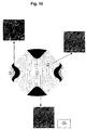
- Fig. 10 and Fig. 11 show SEM images of the structure.
- positions 1 and 2 in Fig. 10 corresponding to Fig. 5 ultrafine ferrite grains of 1 micron or less are produced, while ultrafine grains are not found at position of 3.
- the microstructure of Fig. 11 corresponding to Fig. 7 almost entire region is covered with ultrafine grain structure of ultrafine ferrite grains of 1 micron or less.
- Table 4 shows dynamic properties of material of 13 mm square after four passes. Properties of 24 square bar before rolling are shown for reference. Without causing brittle breakdown at double yield strength and liquid nitrogen temperature, an absorption energy of J was recognized.
- Table 4 Ferrite grain size ( ⁇ m) Yield strength (MPa) Tensile (Mpa) Ductile-brittle transition transition temperature (°C) Absorption energy (J) -120°C Central Vickers Vickers hardness (-) Embodiment 1 0.5 840 850 ⁇ -196 118 290 Embodiment 4 0,6 800 810 ⁇ -196 80 270-310 Comparative example 2 5 460 580 -40 0
- FIG. 12 (a), (b), (c) show SEM images of central part of steel bar (corresponding to position 1 in Fig. 10), in which fine ferrite grains of average grain size of 0.5, 1, and 1.5 microns are formed.
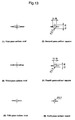
- a steel bar of 15 mm square having a ferrite + pearlite structure of average ferrite grain size of 20 microns of the composition shown in Table 1b was rolled in 6-pass caliber until diameter of 8 mm, using the caliber shown in Fig. 13 at rolling temperature of 450 to 550°C.
- Table 5 shows outline of caliber dimension.
- Fig. 14 shows the sectional shape changes and section reduction ratio in each pass of rolling.
- Fig. 15 shows SEM images of structure after six passes, in which a fine ferrite grain structure was formed in spite of section reduction ratio of about 74%.
- Concerning dynamic properties, the Vickers hardness is shown in the bottom of the photograph in Fig. 15, and an excellent property of over 800 MPa is obtained at tensile strength of 270 to 310.
- Table 5 Longer axis Shorter axis Radius of curvature 1st pass, oval 31 6.8 38 3rd pass, oval 27 5.3 35.9 5th pass, oval 15 6.5 10.7 6th pass, round
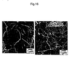
- a steel bar of 24 mm square having a ferrite + pearlite structure of average ferrite grain size of 5 microns of the composition shown in Table 1a was rolled in 7-pass caliber at section reduction ratio of 70% (strain 1.2) until 13 mm square, using the caliber shown in Fig. 1 at rolling temperature of 500°C. It was not rolled by oval shape caliber. As shown in SEM image in Fig. 16, fine grains were not formed in the center of the steel bar.
- a steel bar of 115 mm square of the composition shown in Table 1a was heated to 900°C, and rolled in caliber at section reduction ratio of 94% (strain 3.1) until 24 mm square, using the square shape caliber at rolling temperature of 870 to 850°C. It was not rolled by oval shape caliber. The average grain size was 5 ⁇ m, and fine grains were not formed. Dynamic properties ware shown in Table 2, and the yield strength and tensile strength were respectively 480 and 560 MPa.
- the invention presents a new warm rolling method capable of introducing a greater strain into the material by a smaller section reduction ratio and a smaller number of passes by an easier means, and further presents a manufacturing method of steel materials excellent in strength and ductility, having ultrafine grain structure.
Landscapes
- Chemical & Material Sciences (AREA)
- Engineering & Computer Science (AREA)
- Mechanical Engineering (AREA)
- Physics & Mathematics (AREA)
- Thermal Sciences (AREA)
- Crystallography & Structural Chemistry (AREA)
- Materials Engineering (AREA)
- Metallurgy (AREA)
- Organic Chemistry (AREA)
- Manufacturing & Machinery (AREA)
- Heat Treatment Of Steel (AREA)
- Metal Rolling (AREA)
Abstract
Description
- The present invention relates to a new warm rolling method for manufacturing an ultrafine grain steel material with an ultrafine grain structure of 3 µm or smaller in grain size and excellent in strength and ductility.
- An ultrafine grain steel material can be extremely enhanced in strength without adding alloying elements, and is considered to be decreased extremely in the ductile to brittle transition temperature at the same time, and hence the present inventors have been promoting researches in order to realize the ultrafine grain steel industrially, and have so far invented a method of warm multi-pass rolling (document 1) and a method of multi-directional working (document 2).
- If warm multi-directional rolling can be realized easily, it may lead to wider use of ultrafine grain steel, but it was found not easy in the process of studies by the inventors.
- As one of the technical difficulties, not less than a certain amount of strain must be introduced into the material. For example, the critical strain is 1.5 to 2.3, preferably about 3, and a strain of 3 corresponds to a section reduction ratio of 95%, and a large deformation processing is needed. To obtain a round bar of 10 mm in diameter as final product, warm rolling process must be started from diameter of 45 mm, and to introduce such large strain in warm rolling temperature region of high deformation resistance, a large material is needed. As a result, the number of rolling passes increases.
- If a larger strain can be introduced into the material by a smaller section reduction ratio and a smaller number of passes, an ultrafine grain structure can be obtained more easily, lots of industrial benefits are expected such as enhancement of rolling efficiency.
- The inventors have proposed various methods about multi-directional rolling, such as a method of compressing from multiple directions by using anvil (document 2) and two-directional screw-down rolling technology. Although the multi-directional working is a technology for introducing a large amount of strain efficiently, but processing from at least two directions involved very difficult technical problems.
- Document 1: Japanese Patent Application Laid-Open No. 2000-309850
- Document 2: Japanese Patent Application Laid-Open No. 2001-240912
- The present invention is devised in the light of the above background, and is intended to present a new multi-directional warm rolling method capable of introducing a large strain into the material by a smaller section reduction ratio and a smaller number of passes, by easier means, by further advancing from the findings obtained so far by the inventors, and a manufacturing method of steel material having ultrafine grain structure, and excellent in strength and ductility.
- To solve the problems, it is a first aspect of the invention to present a warm rolling method for manufacturing an ultrafine grain steel material having an ultrafine grain structure of average grain size of 3 µm or less, more particularly a warm rolling method characterized by rolling by a caliber of oval shape and rolling by a caliber of other shape at least once or more respectively, when rolling two passes or more in a rolling temperature range of steel material of 350 to 800°C, and it is a second aspect to present a warm rolling method, in which rolling by a caliber of oval shape is followed by rolling by a caliber of other shape.
- It is a third aspect to present the above-mentioned warm rolling method in which the caliber of other shape is square or round shape.
- It is a fourth aspect to present a warm rolling method in which the rolling by oval shape caliber is executed by 2 times or more to maximum N/2 times or less in the case of N>2, wherein N is the total number of passes, it is a fifth aspect to present a warm rolling method in which continuous two passes rolling are executed, it is a sixth aspect to present a warm rolling method in which the section reduction ratio after square shape caliber rolling from material is 20% or more in two passes rolling by calibers of oval shape and square shape, it is a seventh aspect to present a warm rolling method in which the section reduction ratio is 40% or more in combination rolling by two times, and the section reduction ratio is 60% or more in combination rolling by three times, in combination rolling of two passes rolling by calibers of oval shape and square shape.
- It is an eighth aspect of the invention to present any of the above-mentioned warm rolling methods including a rolling step in which the maximum shorter axis length of material after rolling by oval shape caliber is 75% or less of the material diagonal length before oval rolling, it is a ninth aspect to present a warm rolling method in which a plastic strain of 1.5 or more is introduced at least in a region of 50 vol.% inside of the material, it is a tenth aspect to present a warm rolling method in which a plastic strain of 2 or more is introduced in a region of 90 vol.% or more inside of the material, and it is an eleventh aspect to present a warm rolling method in which the rolling condition parameter Z expressed in the following formula (1) is 11 or more (the structure just before rolling is ferrite, bainite, martensite, pearlite or other Fe crystal structure of bcc) or 20 or more (structure just before rolling is austenite and Fe crystal structure of fcc).

- ε: strain
- τ: time from start of rolling till end (s)
- T: rolling temperature (°C, average of rolling temperature of each pass in the case of multi-pass rolling)
- Q: 254,000 if structure just before rolling is a primary phase of ferrite, bainite, martensite or pearlite; or 300,00 if mother phase is austenite.
- It is a twelfth aspect to present a warm rolling method in which the section reduction ratio of initial material to after final rolling is 90% or less, it is a thirteenth aspect to present a warm rolling method for manufacturing an ultrafine grain steel having an average grain size of C section or L section of 3 microns or less, and it is a fourteenth aspect to present a warm rolling method for manufacturing an ultrafine grain steel having an average grain size of C section or L section of 1 micron or less.
- The invention having such features is devised on the basis of new findings obtained by the investigations by the inventors. That is, hitherto, it is known that caliber rolling which is rolling by using a roll having a hole groove is common as the steel bar manufacturing method, and shapes of caliber are roughly classified into square shape (square shape, diamond shape), oval shape and round shape. By performing caliber (groove roll) rolling in warm rolling temperature region, a structure mainly composed of ultrafine grain ferrite is obtained by multi-pass rolling (document 1). By using the oval shape caliber, it is found to be effective for equiaxialization of ferrite grain shape of L section of steel bar (section parallel to longitudinal direction of bar).
- As a result of intensive studies by the inventors, it has been found that a large strain can be introduced into the material even at a relatively small section reduction ratio, by performing caliber rolling combining oval shape caliber and square, round or other shape caliber, in an appropriate temperature region, so that the technology is established.
-
- Fig. 1 is a diagram of caliber in
embodiment 1. - Fig. 2 is a photograph of C section of steel bar after rolling.
- Fig. 3 is a material mesh diagram.
- Fig. 4 is a diagram showing plastic strain after 1 pass of oval shape caliber rolling.
- Fig. 5 is a diagram showing plastic strain after 2 passes of square shape caliber rolling.
- Fig. 6 is a diagram showing plastic strain after 3 passes of oval shape caliber rolling.
- Fig. 7 is a diagram showing plastic strain after 4 passes of square shape caliber rolling.
- Fig. 8 is a diagram showing plastic strain after 5 passes of oval shape caliber rolling.
- Fig. 9 is a diagram showing plastic strain after 6 passes of round shape caliber rolling.
- Fig. 10 is a SEM image of structure after 2 passes of square shape caliber rolling.
- Fig. 11 is a SEM image of structure after 4 passes of square shape caliber rolling.
- Fig. 12 is a SEM image of structure in
embodiments 2 to 4. - Fig. 13 is a diagram of caliber.
- Fig. 14 is a photograph of C section of steel bar after rolling.
- Fig. 15 is a SEM image of structure.
- Fig. 16 is a SEM image of structure of comparative example 1.
- Fig. 17 is a diagram showing the relation of parameter Z and average grain size.
- The invention has the features as mentioned above, and the individual embodiments are described specifically below.
- The warm rolling method of the invention is capable of manufacturing an ultrafine grain steel material having an ultrafine grain structure of average grain size of 3 µm or less, as mentioned above, by combining rolling by a caliber of oval shape and rolling by a caliber of other shape. In this case, the caliber rolls used in rolling are oval shape caliber and other shape caliber.
- As for the caliber roll of oval shape caliber, the hole shape formed by upper die and lower die is not circular (round), but the shape that circular (round) is flattened. The caliber of other shape combined with the oval shape caliber includes square, rhombus (diamond), round or similar shapes thereof.
- In the invention, as the warm rolling method for manufacturing an ultrafine grain steel material having an ultrafine grain structure of average grain size of 3 µm or less, both of rolling by oval shape caliber and rolling by other shape caliber are executed at least once or more in rolling of two passes or more to steel material in rolling temperature range from 350 to 800°C.
- Actually, a preferable embodiment is that rolling by a caliber of oval shape is followed by rolling by a caliber of other shape, and that the rolling by oval shape caliber is executed by 2 times or more to maximum N/2 times or less in the case of N>2, wherein N is the total number of passes.
- For example, when combining oval shape caliber and square caliber, the rolling condition is considered so as to include, in all passes of rolling, two times or more of combination rolling using oval shape caliber and square shape caliber (oval-square), to include rolling by square shape caliber in the middle of combination rolling of oval-square such as oval-square-square-oval-square, or to roll of 4 passes of oval-square-oval-square, or to roll of 6 passes of oval-square-oval-square-oval-square. In this case, too, the square shape caliber may be replaced by a caliber of round, rhombus or other shape.
- In the rolling method of the invention, a microscopic local orientation difference caused by introduction of large strain by warm rolling originates ultrafine grain, and in the recovery process taking place during or after working, the dislocation density in grain decreases and grain boundary is formed at the same time, and thereby an ultrafine grain structure is formed. However, the recovery is not sufficient if the temperature is low, then deformation texture with high dislocation density is remained. On the other hand, if the temperature is too high, the grain becomes coarse due to discontinuous recrystallization or ordinary grain growth, and ultrafine grain structure of 3 µm or less is not formed. Hence, the rolling temperature is limited within 350 to 800°C.
- In the present invention, ultrafme grains are generated from the deformed grains flattened by warm rolling, and increase along with increase of strain. And, a strain of at least 1.5 is required in order to obtain a structure almost composed of ultrafine grains.
- More specifically, by introducing a plastic strain of 1.5 or more, preferably 2 or more, in the region of at least 50 vol.% of the material inside, ultrafine grains can be formed in this region. Preferably, by introducing a plastic strain of 2 or more in the region of 90 % or more of material inside, an ultrafine grain region can be formed in this region.
- The greater the strain to be introduced is, the greater the orientation differential angle among ultrafine grains is. That is, large angular grain boundaries increase. If a strain of 3 can be introduced, the rate of large angular grain boundaries is sufficient in the grain boundary of ultrafme grains. Therefore, as far as the region of strain of 3 or more is 50% or more, or preferably 80% or more of the entire section, a steel bar of excellent dynamic properties is obtained.
- In addition to processing in principal screw-down direction, when combined with screw-down from other direction forming an angle of about 90°, by applying processing strain from at least two directions, the orientation of ultrafine grains is dispersed, and the rate of large angular grain boundaries can be increased.
- According to the studies accumulated so far by the inventors, it has been disclosed that the average grain size of ultrafine grains formed by warm rolling depends on the processing temperature and strain speed. The grain size becomes smaller along with increase of rolling condition parameter Z of formula (1) as the function of rolling temperature and strain speed. To obtain a structure of average grain size of 1 µm or less, the rolling condition parameter Z must be set higher than a specific critical value. As a result of experiment by one-pass large strain compressive working using small samples, the critical value is found to be about 11 in the case of bcc structure iron (ferrite, bainite, martensite, pearlite, etc.), and about 20 in fcc structure (austenite) (Fig. 17).
- In formula (1), strain (ε) may be a true strain that is industrially easy-to-use strain. For example, supposing the initial area of steel bar to be So, and the area of C section after rolling to be S, the section reduction ratio R is


-
- 1. Obtain stress-strain curve corresponding to the processing temperature of material.
- 2. Prepare for finite element calculation method.
- (1) Create mesh in workpiece.
- (2) Determine contact condition: coefficient of friction = 0.3 coulomb condition.
- (3) Determine stress-strain curve, material property values.
- 3. On the basis of conditions of (1) to (3), calculate by universal finite element method, for example, ABAQUS. The plastic strain ε is calculated in the formula below, and each strain increment is calculated by the universal finite element method code.

- dεxdεydεx: strain increment of x, y, z
- dγxydγyzdγzx: shearing stress increment
- In the warm rolling method of the invention, hence, it is preferred to set the rolling condition so that parameter Z may be 11 or more (bcc structure) or 20 or more (fcc structure).
- Preferred embodiments of the invention include rolling processes wherein section reduction ratio is 20% or more in two passes rolling of oval shape caliber rolling and square shape caliber rolling to material, section reduction ratio is 40% or more in rolling of combined two times of two passes rolling by oval shape caliber and square shape caliber, section reduction ratio is 60% or more in rolling of combined three times of two passes rolling, and the maximum shorter axis length of material after rolling by oval shape caliber is 70% or less of the diagonal length of material before oval rolling.
- Further, concerning the composition of the steel material to which the warm rolling method of the invention can be applied, the composition of steel is not limited at all because mechanism for heightening the strength by phase transformation is not utilized at all and addition of alloying element is not needed for enhancing the strength, and therefore steel materials of wide composition range can be used such as steel types free from phase transformation, for example, ferrite single phase steel or austenite single phase steel.
More specifically, the following composition, by wt.%, is preferred. - C: 0.001% or more to 1.2% or less,
- Si: 0.1% or more to 2% or less,
- Mn: 0.1% or more to 3% or less,
- P: 0.2% or less,
- S: 0.2% or less,
- Al: 1.0% or less,
- N: 0.02% or less,
- Cr, Mo, Cu, and Ni in total: 30% or less,
- Nb, Ti, V in total: 0.5% or less,
- B: 0.01 or less, and
- balance of Fe and inevitable impurities. Such composition free from alloying elements may be presented as an example. The alloy elements such as Cr, Mo, Cu, Ni, Nb, T, V, B, etc. may be added more than the specified range as required, or may not be added at all.
- Presenting embodiments, the invention is more specifically described below. But it must be noted that the invention is not limited to the embodiments alone.
- Table 2 shows chemical composition of sample steels used in embodiments (the balance is Fe).
Table 2 Chemical composition of sample steels (mass %) C Si Mn P S Al a 0.15 0.3 1.5 0.01 0.001 0.03 b 0.11 0.3 0.5 0.02 0.005 0.03 - A steel bar of 24 mm square having a ferrite + pearlite structure of average ferrite grain size of 5 microns of the composition shown in Table 2a was rolled in 6-pass caliber using the caliber shown in Fig. 1 at rolling temperature of 520 to 450°C. In Fig. 1, the outline of caliber dimension (mm) is as shown in Table 3.
Table 3 Longer axis Shorter axis Radius of curvature 1st pass, oval 54 12 64 3rd pass, oval 41 9 49 5th pass, oval 19 10 12 6th pass, round Diameter 12 - Fig. 2 shows the sectional shape changes and section reduction ratio of each pass of rolling. The section reduction ratio of rolling the 24 x 24 mm square bar by oval shape caliber in the first pass is 37%, the section reduction ratio of rolling material by square shape caliber in the second pass is 21%, the section reduction ratio of rolling material by oval shape caliber in the third pass is 15%, the section reduction ratio of rolling material by square shape caliber in the fourth pass is 24%, the section reduction ratio of rolling material by oval shape caliber in the fifth pass is 13%, and the section reduction ratio of rolling material by round shape caliber in the sixth pass is 12%. The section reduction ratio from the material to the square bar of 17 mm in the second pass is 44%, the section reduction ratio from the material to the square bar of 13 mm in the fourth pass is 71%, and the section reduction ratio from the material to the round bar of 12.5 mm in the sixth pass is 80%.
- Fig. 3 to Fig. 9 show distribution of plastic strain in the material inside calculated by the finite element method. Fig. 5 suggests there is a region exceeding the plastic strain of 1.5 in the material already in the second pass of oval-square shape caliber. Its area rate is 75%. As shown in Fig. 6, after rolling of three passes of oval-square-oval, a region over plastic strain of 2 occupies 92% of all area, and in Fig. 7, after rolling of four passes of oval-square-oval-square, a region over plastic strain of 3 occupies 95%, and after oval-round rolling in Fig. 9, the plastic strain is 3 or more in 100% region.
- The section reduction ratio after two passes is about 44% (when section reduction ratio R is converted merely into true strain e, from e = -Ln(1-R/100), e = 0.67), after four passes, 71% (section reduction R merely converted into true strain of 1.23), and after six passes, 80% (section reduction R merely converted into true strain of 1.61), but it is found that a very large plastic strain is formed inside the material. This is because the oval shape caliber and square shape caliber are combined in rolling, and the strain is far larger than the strain calculated from a mere section reduction area.
- Fig. 10 and Fig. 11 show SEM images of the structure. In
positions - Table 4 shows dynamic properties of material of 13 mm square after four passes. Properties of 24 square bar before rolling are shown for reference. Without causing brittle breakdown at double yield strength and liquid nitrogen temperature, an absorption energy of J was recognized.
Table 4 Ferrite grain size (µm) Yield strength (MPa) Tensile (Mpa) Ductile-brittle transition transition temperature (°C) Absorption energy (J) -120°C Central Vickers Vickers hardness (-) Embodiment 10.5 840 850 <-196 118 290 Embodiment 40,6 800 810 <-196 80 270-310 Comparative example 2 5 460 580 -40 0 - A steel bar of 24 mm square having a ferrite + pearlite structure of average ferrite grain size of 5 microns of the composition shown in Table 1a was rolled in 2-pass caliber using the caliber shown in Fig. 1 (1), (2) at rolling temperature of 400°C, 600°C, and 700°C. Fig. 12 (a), (b), (c) show SEM images of central part of steel bar (corresponding to
position ① in Fig. 10), in which fine ferrite grains of average grain size of 0.5, 1, and 1.5 microns are formed. - A steel bar of 15 mm square having a ferrite + pearlite structure of average ferrite grain size of 20 microns of the composition shown in Table 1b was rolled in 6-pass caliber until diameter of 8 mm, using the caliber shown in Fig. 13 at rolling temperature of 450 to 550°C. Table 5 shows outline of caliber dimension. Fig. 14 shows the sectional shape changes and section reduction ratio in each pass of rolling. Fig. 15 shows SEM images of structure after six passes, in which a fine ferrite grain structure was formed in spite of section reduction ratio of about 74%. Concerning dynamic properties, the Vickers hardness is shown in the bottom of the photograph in Fig. 15, and an excellent property of over 800 MPa is obtained at tensile strength of 270 to 310.
Table 5 Longer axis Shorter axis Radius of curvature 1st pass, oval 31 6.8 38 3rd pass, oval 27 5.3 35.9 5th pass, oval 15 6.5 10.7 6th pass, round Diameter 8 - A steel bar of 24 mm square having a ferrite + pearlite structure of average ferrite grain size of 5 microns of the composition shown in Table 1a was rolled in 7-pass caliber at section reduction ratio of 70% (strain 1.2) until 13 mm square, using the caliber shown in Fig. 1 at rolling temperature of 500°C. It was not rolled by oval shape caliber. As shown in SEM image in Fig. 16, fine grains were not formed in the center of the steel bar.
- A steel bar of 115 mm square of the composition shown in Table 1a was heated to 900°C, and rolled in caliber at section reduction ratio of 94% (strain 3.1) until 24 mm square, using the square shape caliber at rolling temperature of 870 to 850°C. It was not rolled by oval shape caliber. The average grain size was 5 µm, and fine grains were not formed. Dynamic properties ware shown in Table 2, and the yield strength and tensile strength were respectively 480 and 560 MPa.
- As described herein, the invention presents a new warm rolling method capable of introducing a greater strain into the material by a smaller section reduction ratio and a smaller number of passes by an easier means, and further presents a manufacturing method of steel materials excellent in strength and ductility, having ultrafine grain structure.
Claims (14)
- A warm rolling method for manufacturing an ultrafine grain steel material having an ultrafine grain structure of average grain size of 3 µm or less, which comprises rolling by a caliber of oval shape and rolling by a caliber of other shape at least once or more each when rolling two passes or more to a steel material in a rolling temperature range of 350 to 800°C.
- The warm rolling method of claim 1, wherein rolling by a caliber of oval shape is followed by rolling by a caliber of other shape.
- The warm rolling method of claim 1 or 2, wherein the caliber of other shape is square or round shape.
- The warm rolling method of any one of claims 1 to 3, wherein the rolling by oval shape caliber is executed by 2 times or more to maximum N/2 times or less in the case of N>2, wherein N is the total number of passes.
- The warm rolling method of any one of claims 1 to 3, wherein continuous two passes rolling are executed.
- The warm rolling method of claim 5, wherein the section reduction ratio after square shape caliber rolling from material is 20% or more in two passes rolling by calibers of oval shape and square shape.
- The warm rolling method of any one of claims 1 to 3, wherein the section reduction ratio is, in combination rolling of two passes rolling by calibers of oval shape and square shape, 40% or more in combination rolling by two times, and the section reduction ratio is 60% or more in combination rolling by three times.
- The warm rolling method of any one of claims 1 to 7, further including a rolling step in which the maximum shorter axis length of material after rolling by oval shape caliber is 75% or less of the material diagonal length before oval rolling.
- The warm rolling method of any one of claims 1 to 8, wherein a plastic strain of 1.5 or more is introduced at least in a region of 50 vol.% inside of the material.
- The warm rolling method of claim 9, wherein a plastic strain of 2 or more is introduced in a region of 90 vol.% or more inside of the material.
- The warm rolling method of any one of claims 1 to 10, wherein the rolling condition parameter Z expressed in the following formula (1) is 11 or more in the case that crystal structure of Fe just before rolling is bcc such as the structure of ferrite, bainite, martensite, pearlite or other, or 20 or more in the case that structure just before rolling is austenite and Fe crystal structure is fcc;
 ε: straint: time from start of rolling till end (s)T: rolling temperature (°C, average of rolling temperature of each pass in the case of multi-pass rolling)Q: 254,000 if structure just before rolling is a primary phase of ferrite, bainite, martensite or pearlite; or 300,00 if mother phase is austenite.
 - The warm rolling method of any one of claims 1 to 11, wherein the section reduction ratio of initial material to final rolling is 90% or less.
- The warm rolling method of any one of claims 1 to 12, wherein an ultrafine grain steel having an average grain size of C section or L section of 3 microns or less is manufactured.
- The warm rolling method of any one of claims 1 to 12, wherein an ultrafine grain steel having an average grain size of C section or L section of 1 micron or less is manufactured.
Applications Claiming Priority (2)
| Application Number | Priority Date | Filing Date | Title |
|---|---|---|---|
| JP2003180290A JP4221497B2 (en) | 2003-05-20 | 2003-05-20 | Warm rolling method for ultra-fine grain steel |
| PCT/JP2004/007277 WO2004104235A1 (en) | 2003-05-20 | 2004-05-20 | Warm rolling method |
Publications (3)
| Publication Number | Publication Date |
|---|---|
| EP1642988A1 true EP1642988A1 (en) | 2006-04-05 |
| EP1642988A4 EP1642988A4 (en) | 2006-11-15 |
| EP1642988B1 EP1642988B1 (en) | 2011-07-20 |
Family
ID=33475458
Family Applications (1)
| Application Number | Title | Priority Date | Filing Date |
|---|---|---|---|
| EP04734146A Expired - Lifetime EP1642988B1 (en) | 2003-05-20 | 2004-05-20 | Warm rolling method |
Country Status (7)
| Country | Link |
|---|---|
| US (1) | US20060191613A1 (en) |
| EP (1) | EP1642988B1 (en) |
| JP (1) | JP4221497B2 (en) |
| KR (1) | KR100749381B1 (en) |
| CN (1) | CN100366761C (en) |
| TW (1) | TWI266659B (en) |
| WO (1) | WO2004104235A1 (en) |
Cited By (1)
| Publication number | Priority date | Publication date | Assignee | Title |
|---|---|---|---|---|
| RU2515781C1 (en) * | 2012-12-28 | 2014-05-20 | Анатолий Васильевич Алдунин | Method to produce metal rhombic profiles |
Families Citing this family (9)
| Publication number | Priority date | Publication date | Assignee | Title |
|---|---|---|---|---|
| JP4992064B2 (en) * | 2008-01-09 | 2012-08-08 | タマティーエルオー株式会社 | Strong processing apparatus and strong processing method |
| JP5843127B2 (en) * | 2011-02-28 | 2016-01-13 | 国立研究開発法人物質・材料研究機構 | Manufacturing method of high strength nonmagnetic austenitic stainless steel |
| JP5733857B2 (en) * | 2011-02-28 | 2015-06-10 | 国立研究開発法人物質・材料研究機構 | Non-magnetic high-strength molded article and its manufacturing method |
| CN102284488B (en) * | 2011-07-22 | 2013-01-30 | 四川三洲特种钢管有限公司 | Symmetric hole-shaped curve cycle roll |
| KR101355464B1 (en) * | 2011-12-20 | 2014-01-28 | 주식회사 포스코 | Rolling method of carbon steels |
| CN102825097A (en) * | 2012-09-07 | 2012-12-19 | 白银有色集团股份有限公司 | Production method of alloy HMn60-3-1-0.75 large section bar |
| JP5988065B2 (en) * | 2015-05-14 | 2016-09-07 | 国立研究開発法人物質・材料研究機構 | High strength nonmagnetic austenitic stainless steel |
| CN109127730B (en) * | 2018-08-28 | 2019-10-01 | 成都蜀虹装备制造股份有限公司 | A kind of 5356 aluminium alloy rod continuous casting and rolling production systems |
| CN111360080B (en) * | 2020-03-10 | 2024-10-15 | 宝鸡市天罡钛业有限责任公司 | Pass system for rolling hexagonal section titanium and titanium alloy section bar and rolling method |
Family Cites Families (13)
| Publication number | Priority date | Publication date | Assignee | Title |
|---|---|---|---|---|
| JPS5816704A (en) * | 1981-07-21 | 1983-01-31 | Sumitomo Metal Ind Ltd | Caliber rolling method |
| CA1262226A (en) * | 1984-12-28 | 1989-10-10 | Fukukazu Nakasato | Method for producing steel bars having improved low temperature toughness and steel bars produced thereby |
| CA2066475C (en) * | 1991-05-06 | 1997-06-03 | Terence M. Shore | Method and apparatus for continuously hot rolling of ferrous long products |
| EP1010476A3 (en) * | 1998-12-14 | 2003-09-03 | SMS Demag AG | Roll stand arrangement for the rolling of wire |
| JP3904351B2 (en) * | 1999-02-26 | 2007-04-11 | 独立行政法人物質・材料研究機構 | High-strength and high-toughness rod and its manufacturing method |
| JP2000301204A (en) * | 1999-04-15 | 2000-10-31 | Daido Steel Co Ltd | Multi-size wire rod and bar rolling method and rolling device |
| JP2000309823A (en) * | 1999-04-23 | 2000-11-07 | Nippon Steel Corp | Method for producing hot-rolled silicon steel sheet with uniform magnetic properties |
| JP3796536B2 (en) | 2000-02-29 | 2006-07-12 | 独立行政法人物質・材料研究機構 | Large strain uniform introduction processing method |
| US6546777B2 (en) * | 2000-09-08 | 2003-04-15 | Morgan Construction Company | Method and apparatus for reducing and sizing hot rolled ferrous products |
| JP2002137002A (en) * | 2000-10-30 | 2002-05-14 | Daido Steel Co Ltd | Guideless rolling method in hot rolling |
| JP2002192201A (en) * | 2000-12-26 | 2002-07-10 | National Institute For Materials Science | Metal processing method to introduce large strain by forging / rolling line |
| JP3983065B2 (en) * | 2002-02-28 | 2007-09-26 | 独立行政法人物質・材料研究機構 | Manufacturing method of thick steel plate having ultrafine grain structure and thick steel plate |
| CN1705763A (en) * | 2002-10-17 | 2005-12-07 | 独立行政法人物质·材料研究机构 | Formed product and method for production thereof |
-
2003
- 2003-05-20 JP JP2003180290A patent/JP4221497B2/en not_active Expired - Lifetime
-
2004
- 2004-05-20 TW TW093114215A patent/TWI266659B/en not_active IP Right Cessation
- 2004-05-20 WO PCT/JP2004/007277 patent/WO2004104235A1/en not_active Ceased
- 2004-05-20 KR KR1020057021834A patent/KR100749381B1/en not_active Expired - Lifetime
- 2004-05-20 US US10/557,416 patent/US20060191613A1/en not_active Abandoned
- 2004-05-20 EP EP04734146A patent/EP1642988B1/en not_active Expired - Lifetime
- 2004-05-20 CN CNB2004800136487A patent/CN100366761C/en not_active Expired - Lifetime
Cited By (1)
| Publication number | Priority date | Publication date | Assignee | Title |
|---|---|---|---|---|
| RU2515781C1 (en) * | 2012-12-28 | 2014-05-20 | Анатолий Васильевич Алдунин | Method to produce metal rhombic profiles |
Also Published As
| Publication number | Publication date |
|---|---|
| CN1791688A (en) | 2006-06-21 |
| US20060191613A1 (en) | 2006-08-31 |
| TWI266659B (en) | 2006-11-21 |
| EP1642988A4 (en) | 2006-11-15 |
| JP4221497B2 (en) | 2009-02-12 |
| JP2004346420A (en) | 2004-12-09 |
| TW200510084A (en) | 2005-03-16 |
| KR20060035603A (en) | 2006-04-26 |
| WO2004104235A1 (en) | 2004-12-02 |
| CN100366761C (en) | 2008-02-06 |
| EP1642988B1 (en) | 2011-07-20 |
| KR100749381B1 (en) | 2007-08-14 |
Similar Documents
| Publication | Publication Date | Title |
|---|---|---|
| DE68922075T2 (en) | Process for the production of a metallic material with an ultrafine grain structure. | |
| EP1309734B1 (en) | Highly stable, steel and steel strips or steel sheets cold-formed, method for the production of steel strips and uses of said steel | |
| CN104540974B (en) | Cold forging round stock | |
| EP2177634B1 (en) | Process for production of duplex stainless steel tubes | |
| EP2042616B1 (en) | ROLLED AUSTENITE STAINLESS STEEL PLATE HAVING THICHKESS OF 100 mm OR MORE AND METHOD FOR PRODUCTION THEREOF | |
| CN108474073B (en) | Steel wire for non-quenched and tempered mechanical parts and non-quenched and tempered mechanical parts | |
| EP3597783B1 (en) | H-section steel and method of producing the same | |
| EP2792761B1 (en) | High-strength extra-thick steel h-beam | |
| EP1573075A1 (en) | Method for producing a steel product | |
| EP1699582B1 (en) | Method for the generation of hot strips of light gauge steel | |
| EP0903412A2 (en) | Ultra-fine texture steel and method for producing it | |
| EP1642988B1 (en) | Warm rolling method | |
| EP3521475A1 (en) | Electric resistance-welded steel pipe for torsion beam | |
| JP2004211199A (en) | High-strength hot-rolled steel sheet having excellent fatigue resistance and excellent strength-ductility balance, and method for producing the same | |
| EP3754044B1 (en) | High-strength steel sheet with excellent ductility and hole-expandability | |
| EP1398390B1 (en) | Steel with a very fine ferritic and martensitic microstructure having a high tensile strength | |
| EP4206337A1 (en) | Plate and thermomechanical processing method of a raw material for producing a plate | |
| JP4164589B2 (en) | Manufacturing method of ultra-fine structure steel | |
| KR20050072762A (en) | Formed product and method for production thereof | |
| JP2004060046A (en) | Molded product and its manufacturing method | |
| JP2003253332A (en) | Method of manufacturing thick steel plate having ultra-fine grain structure and thick steel plate | |
| JP2000309850A (en) | High strength and high toughness bar and its manufacturing method | |
| JP2001247931A (en) | Non-tempered high-strength seamless steel pipe and method for producing the same | |
| EP1627928B1 (en) | Controlled warm-rolling method | |
| DE69611950T2 (en) | Process for the production of hot-rolled steel sheet with a very high elastic limit and steel sheet |
Legal Events
| Date | Code | Title | Description |
|---|---|---|---|
| PUAI | Public reference made under article 153(3) epc to a published international application that has entered the european phase |
Free format text: ORIGINAL CODE: 0009012 |
|
| 17P | Request for examination filed |
Effective date: 20051220 |
|
| AK | Designated contracting states |
Kind code of ref document: A1 Designated state(s): DE FR GB IT |
|
| DAX | Request for extension of the european patent (deleted) | ||
| RBV | Designated contracting states (corrected) |
Designated state(s): DE FR GB IT |
|
| A4 | Supplementary search report drawn up and despatched |
Effective date: 20061018 |
|
| RIC1 | Information provided on ipc code assigned before grant |
Ipc: C21D 8/00 20060101ALI20061012BHEP Ipc: C21D 8/06 20060101AFI20041208BHEP Ipc: B21B 1/18 20060101ALI20061012BHEP |
|
| 17Q | First examination report despatched |
Effective date: 20070302 |
|
| GRAP | Despatch of communication of intention to grant a patent |
Free format text: ORIGINAL CODE: EPIDOSNIGR1 |
|
| GRAS | Grant fee paid |
Free format text: ORIGINAL CODE: EPIDOSNIGR3 |
|
| GRAA | (expected) grant |
Free format text: ORIGINAL CODE: 0009210 |
|
| AK | Designated contracting states |
Kind code of ref document: B1 Designated state(s): DE FR GB IT |
|
| REG | Reference to a national code |
Ref country code: GB Ref legal event code: FG4D |
|
| REG | Reference to a national code |
Ref country code: DE Ref legal event code: R096 Ref document number: 602004033547 Country of ref document: DE Effective date: 20110915 |
|
| PLBE | No opposition filed within time limit |
Free format text: ORIGINAL CODE: 0009261 |
|
| STAA | Information on the status of an ep patent application or granted ep patent |
Free format text: STATUS: NO OPPOSITION FILED WITHIN TIME LIMIT |
|
| 26N | No opposition filed |
Effective date: 20120423 |
|
| REG | Reference to a national code |
Ref country code: DE Ref legal event code: R097 Ref document number: 602004033547 Country of ref document: DE Effective date: 20120423 |
|
| REG | Reference to a national code |
Ref country code: FR Ref legal event code: PLFP Year of fee payment: 13 |
|
| REG | Reference to a national code |
Ref country code: FR Ref legal event code: PLFP Year of fee payment: 14 |
|
| REG | Reference to a national code |
Ref country code: FR Ref legal event code: PLFP Year of fee payment: 15 |
|
| REG | Reference to a national code |
Ref country code: DE Ref legal event code: R082 Ref document number: 602004033547 Country of ref document: DE Representative=s name: DEHNS GERMANY PARTNERSCHAFT MBB, DE Ref country code: DE Ref legal event code: R082 Ref document number: 602004033547 Country of ref document: DE Representative=s name: DEHNSGERMANY PARTNERSCHAFT VON PATENTANWAELTEN, DE |
|
| PGFP | Annual fee paid to national office [announced via postgrant information from national office to epo] |
Ref country code: IT Payment date: 20230526 Year of fee payment: 20 Ref country code: FR Payment date: 20230525 Year of fee payment: 20 Ref country code: DE Payment date: 20220620 Year of fee payment: 20 |
|
| PGFP | Annual fee paid to national office [announced via postgrant information from national office to epo] |
Ref country code: GB Payment date: 20230523 Year of fee payment: 20 |
|
| REG | Reference to a national code |
Ref country code: DE Ref legal event code: R071 Ref document number: 602004033547 Country of ref document: DE |
|
| REG | Reference to a national code |
Ref country code: GB Ref legal event code: PE20 Expiry date: 20240519 |
|
| PG25 | Lapsed in a contracting state [announced via postgrant information from national office to epo] |
Ref country code: GB Free format text: LAPSE BECAUSE OF EXPIRATION OF PROTECTION Effective date: 20240519 |
|
| PG25 | Lapsed in a contracting state [announced via postgrant information from national office to epo] |
Ref country code: GB Free format text: LAPSE BECAUSE OF EXPIRATION OF PROTECTION Effective date: 20240519 |