EP1641040A2 - Thermally conductive sheet and method for producing the same - Google Patents
Thermally conductive sheet and method for producing the same Download PDFInfo
- Publication number
- EP1641040A2 EP1641040A2 EP20050020238 EP05020238A EP1641040A2 EP 1641040 A2 EP1641040 A2 EP 1641040A2 EP 20050020238 EP20050020238 EP 20050020238 EP 05020238 A EP05020238 A EP 05020238A EP 1641040 A2 EP1641040 A2 EP 1641040A2
- Authority
- EP
- European Patent Office
- Prior art keywords
- sheet
- thermally conductive
- thin film
- film
- conductive sheet
- Prior art date
- Legal status (The legal status is an assumption and is not a legal conclusion. Google has not performed a legal analysis and makes no representation as to the accuracy of the status listed.)
- Granted
Links
- 238000004519 manufacturing process Methods 0.000 title claims abstract description 10
- 239000010410 layer Substances 0.000 claims abstract description 112
- 239000010409 thin film Substances 0.000 claims abstract description 110
- 229920000058 polyacrylate Polymers 0.000 claims abstract description 31
- 239000000853 adhesive Substances 0.000 claims abstract description 25
- 230000001070 adhesive effect Effects 0.000 claims abstract description 25
- 239000011231 conductive filler Substances 0.000 claims abstract description 23
- 239000002344 surface layer Substances 0.000 claims abstract description 23
- 239000010408 film Substances 0.000 claims description 162
- 239000000463 material Substances 0.000 claims description 105
- 239000012779 reinforcing material Substances 0.000 claims description 42
- 238000000034 method Methods 0.000 claims description 14
- 238000000465 moulding Methods 0.000 claims description 14
- 239000000835 fiber Substances 0.000 claims description 7
- 239000012209 synthetic fiber Substances 0.000 claims 1
- 229920002994 synthetic fiber Polymers 0.000 claims 1
- 239000000126 substance Substances 0.000 abstract description 18
- 229920000642 polymer Polymers 0.000 abstract description 13
- 239000000178 monomer Substances 0.000 abstract description 12
- 150000001875 compounds Chemical class 0.000 abstract description 8
- 238000005336 cracking Methods 0.000 abstract description 7
- 238000012360 testing method Methods 0.000 description 22
- 239000011248 coating agent Substances 0.000 description 19
- 238000000576 coating method Methods 0.000 description 19
- 229920006267 polyester film Polymers 0.000 description 19
- 230000000052 comparative effect Effects 0.000 description 15
- 239000000203 mixture Substances 0.000 description 15
- YCKRFDGAMUMZLT-UHFFFAOYSA-N Fluorine atom Chemical compound [F] YCKRFDGAMUMZLT-UHFFFAOYSA-N 0.000 description 14
- 239000011737 fluorine Substances 0.000 description 14
- 229910052731 fluorine Inorganic materials 0.000 description 14
- NIXOWILDQLNWCW-UHFFFAOYSA-N acrylic acid group Chemical group C(C=C)(=O)O NIXOWILDQLNWCW-UHFFFAOYSA-N 0.000 description 11
- 229920000728 polyester Polymers 0.000 description 11
- 229920005989 resin Polymers 0.000 description 10
- 239000011347 resin Substances 0.000 description 10
- 150000001252 acrylic acid derivatives Chemical class 0.000 description 8
- UHESRSKEBRADOO-UHFFFAOYSA-N ethyl carbamate;prop-2-enoic acid Chemical compound OC(=O)C=C.CCOC(N)=O UHESRSKEBRADOO-UHFFFAOYSA-N 0.000 description 8
- 230000015572 biosynthetic process Effects 0.000 description 7
- IFXDUNDBQDXPQZ-UHFFFAOYSA-N 2-methylbutan-2-yl 2-ethylhexaneperoxoate Chemical compound CCCCC(CC)C(=O)OOC(C)(C)CC IFXDUNDBQDXPQZ-UHFFFAOYSA-N 0.000 description 6
- NIXOWILDQLNWCW-UHFFFAOYSA-M Acrylate Chemical compound [O-]C(=O)C=C NIXOWILDQLNWCW-UHFFFAOYSA-M 0.000 description 6
- -1 alumina Chemical compound 0.000 description 6
- 239000003795 chemical substances by application Substances 0.000 description 6
- 150000002222 fluorine compounds Chemical class 0.000 description 6
- 229910044991 metal oxide Inorganic materials 0.000 description 6
- 150000004706 metal oxides Chemical class 0.000 description 6
- 125000005395 methacrylic acid group Chemical group 0.000 description 6
- 229920001296 polysiloxane Polymers 0.000 description 6
- 229910052782 aluminium Inorganic materials 0.000 description 5
- XAGFODPZIPBFFR-UHFFFAOYSA-N aluminium Chemical compound [Al] XAGFODPZIPBFFR-UHFFFAOYSA-N 0.000 description 5
- 125000000524 functional group Chemical group 0.000 description 5
- UCNNJGDEJXIUCC-UHFFFAOYSA-L hydroxy(oxo)iron;iron Chemical compound [Fe].O[Fe]=O.O[Fe]=O UCNNJGDEJXIUCC-UHFFFAOYSA-L 0.000 description 5
- TWNQGVIAIRXVLR-UHFFFAOYSA-N oxo(oxoalumanyloxy)alumane Chemical compound O=[Al]O[Al]=O TWNQGVIAIRXVLR-UHFFFAOYSA-N 0.000 description 5
- CPLXHLVBOLITMK-UHFFFAOYSA-N Magnesium oxide Chemical compound [Mg]=O CPLXHLVBOLITMK-UHFFFAOYSA-N 0.000 description 4
- VYPSYNLAJGMNEJ-UHFFFAOYSA-N Silicium dioxide Chemical compound O=[Si]=O VYPSYNLAJGMNEJ-UHFFFAOYSA-N 0.000 description 4
- 238000005520 cutting process Methods 0.000 description 4
- 239000000945 filler Substances 0.000 description 4
- 239000004519 grease Substances 0.000 description 4
- 239000002245 particle Substances 0.000 description 4
- WZESLRDFSNLECD-UHFFFAOYSA-N phenyl prop-2-eneperoxoate Chemical compound C=CC(=O)OOC1=CC=CC=C1 WZESLRDFSNLECD-UHFFFAOYSA-N 0.000 description 4
- KCTAWXVAICEBSD-UHFFFAOYSA-N prop-2-enoyloxy prop-2-eneperoxoate Chemical compound C=CC(=O)OOOC(=O)C=C KCTAWXVAICEBSD-UHFFFAOYSA-N 0.000 description 4
- 230000001681 protective effect Effects 0.000 description 4
- 239000004743 Polypropylene Substances 0.000 description 3
- 239000006087 Silane Coupling Agent Substances 0.000 description 3
- 230000006835 compression Effects 0.000 description 3
- 238000007906 compression Methods 0.000 description 3
- 229910052751 metal Inorganic materials 0.000 description 3
- 239000002184 metal Substances 0.000 description 3
- 229920001778 nylon Polymers 0.000 description 3
- 229920001155 polypropylene Polymers 0.000 description 3
- 229910052582 BN Inorganic materials 0.000 description 2
- PZNSFCLAULLKQX-UHFFFAOYSA-N Boron nitride Chemical compound N#B PZNSFCLAULLKQX-UHFFFAOYSA-N 0.000 description 2
- RYGMFSIKBFXOCR-UHFFFAOYSA-N Copper Chemical compound [Cu] RYGMFSIKBFXOCR-UHFFFAOYSA-N 0.000 description 2
- 229910052581 Si3N4 Inorganic materials 0.000 description 2
- BQCADISMDOOEFD-UHFFFAOYSA-N Silver Chemical compound [Ag] BQCADISMDOOEFD-UHFFFAOYSA-N 0.000 description 2
- PNEYBMLMFCGWSK-UHFFFAOYSA-N aluminium oxide Inorganic materials [O-2].[O-2].[O-2].[Al+3].[Al+3] PNEYBMLMFCGWSK-UHFFFAOYSA-N 0.000 description 2
- 238000003490 calendering Methods 0.000 description 2
- 239000004020 conductor Substances 0.000 description 2
- 239000010949 copper Substances 0.000 description 2
- 229910052802 copper Inorganic materials 0.000 description 2
- PMHQVHHXPFUNSP-UHFFFAOYSA-M copper(1+);methylsulfanylmethane;bromide Chemical compound Br[Cu].CSC PMHQVHHXPFUNSP-UHFFFAOYSA-M 0.000 description 2
- 238000004132 cross linking Methods 0.000 description 2
- 238000007756 gravure coating Methods 0.000 description 2
- 239000007788 liquid Substances 0.000 description 2
- 239000000395 magnesium oxide Substances 0.000 description 2
- 238000005259 measurement Methods 0.000 description 2
- 238000000691 measurement method Methods 0.000 description 2
- 150000002739 metals Chemical class 0.000 description 2
- 238000002156 mixing Methods 0.000 description 2
- 230000003014 reinforcing effect Effects 0.000 description 2
- 239000000377 silicon dioxide Substances 0.000 description 2
- HQVNEWCFYHHQES-UHFFFAOYSA-N silicon nitride Chemical compound N12[Si]34N5[Si]62N3[Si]51N64 HQVNEWCFYHHQES-UHFFFAOYSA-N 0.000 description 2
- 229920002379 silicone rubber Polymers 0.000 description 2
- 239000004945 silicone rubber Substances 0.000 description 2
- 229910052709 silver Inorganic materials 0.000 description 2
- 239000004332 silver Substances 0.000 description 2
- 238000010345 tape casting Methods 0.000 description 2
- 229920000049 Carbon (fiber) Polymers 0.000 description 1
- 229920000742 Cotton Polymers 0.000 description 1
- 239000004820 Pressure-sensitive adhesive Substances 0.000 description 1
- 235000010724 Wisteria floribunda Nutrition 0.000 description 1
- 229920000800 acrylic rubber Polymers 0.000 description 1
- 229920006231 aramid fiber Polymers 0.000 description 1
- 239000004917 carbon fiber Substances 0.000 description 1
- 238000001816 cooling Methods 0.000 description 1
- KPUWHANPEXNPJT-UHFFFAOYSA-N disiloxane Chemical class [SiH3]O[SiH3] KPUWHANPEXNPJT-UHFFFAOYSA-N 0.000 description 1
- 230000001747 exhibiting effect Effects 0.000 description 1
- 239000003365 glass fiber Substances 0.000 description 1
- 239000012784 inorganic fiber Substances 0.000 description 1
- 230000010354 integration Effects 0.000 description 1
- VNWKTOKETHGBQD-UHFFFAOYSA-N methane Chemical compound C VNWKTOKETHGBQD-UHFFFAOYSA-N 0.000 description 1
- 239000004745 nonwoven fabric Substances 0.000 description 1
- 239000003960 organic solvent Substances 0.000 description 1
- 238000013031 physical testing Methods 0.000 description 1
- 229920013716 polyethylene resin Polymers 0.000 description 1
- 229920003225 polyurethane elastomer Polymers 0.000 description 1
- 230000005855 radiation Effects 0.000 description 1
- 229920002050 silicone resin Polymers 0.000 description 1
- 229920003002 synthetic resin Polymers 0.000 description 1
- 239000000057 synthetic resin Substances 0.000 description 1
- 229920001187 thermosetting polymer Polymers 0.000 description 1
- 239000002759 woven fabric Substances 0.000 description 1
Images
Classifications
-
- H—ELECTRICITY
- H01—ELECTRIC ELEMENTS
- H01L—SEMICONDUCTOR DEVICES NOT COVERED BY CLASS H10
- H01L23/00—Details of semiconductor or other solid state devices
- H01L23/34—Arrangements for cooling, heating, ventilating or temperature compensation ; Temperature sensing arrangements
- H01L23/36—Selection of materials, or shaping, to facilitate cooling or heating, e.g. heatsinks
- H01L23/373—Cooling facilitated by selection of materials for the device or materials for thermal expansion adaptation, e.g. carbon
- H01L23/3735—Laminates or multilayers, e.g. direct bond copper ceramic substrates
-
- H—ELECTRICITY
- H01—ELECTRIC ELEMENTS
- H01L—SEMICONDUCTOR DEVICES NOT COVERED BY CLASS H10
- H01L21/00—Processes or apparatus adapted for the manufacture or treatment of semiconductor or solid state devices or of parts thereof
- H01L21/02—Manufacture or treatment of semiconductor devices or of parts thereof
- H01L21/04—Manufacture or treatment of semiconductor devices or of parts thereof the devices having at least one potential-jump barrier or surface barrier, e.g. PN junction, depletion layer or carrier concentration layer
- H01L21/48—Manufacture or treatment of parts, e.g. containers, prior to assembly of the devices, using processes not provided for in a single one of the subgroups H01L21/06 - H01L21/326
- H01L21/4814—Conductive parts
- H01L21/4871—Bases, plates or heatsinks
- H01L21/4882—Assembly of heatsink parts
-
- H—ELECTRICITY
- H01—ELECTRIC ELEMENTS
- H01L—SEMICONDUCTOR DEVICES NOT COVERED BY CLASS H10
- H01L23/00—Details of semiconductor or other solid state devices
- H01L23/34—Arrangements for cooling, heating, ventilating or temperature compensation ; Temperature sensing arrangements
- H01L23/36—Selection of materials, or shaping, to facilitate cooling or heating, e.g. heatsinks
- H01L23/373—Cooling facilitated by selection of materials for the device or materials for thermal expansion adaptation, e.g. carbon
- H01L23/3737—Organic materials with or without a thermoconductive filler
-
- H—ELECTRICITY
- H01—ELECTRIC ELEMENTS
- H01L—SEMICONDUCTOR DEVICES NOT COVERED BY CLASS H10
- H01L2924/00—Indexing scheme for arrangements or methods for connecting or disconnecting semiconductor or solid-state bodies as covered by H01L24/00
- H01L2924/0001—Technical content checked by a classifier
- H01L2924/0002—Not covered by any one of groups H01L24/00, H01L24/00 and H01L2224/00
-
- Y—GENERAL TAGGING OF NEW TECHNOLOGICAL DEVELOPMENTS; GENERAL TAGGING OF CROSS-SECTIONAL TECHNOLOGIES SPANNING OVER SEVERAL SECTIONS OF THE IPC; TECHNICAL SUBJECTS COVERED BY FORMER USPC CROSS-REFERENCE ART COLLECTIONS [XRACs] AND DIGESTS
- Y10—TECHNICAL SUBJECTS COVERED BY FORMER USPC
- Y10T—TECHNICAL SUBJECTS COVERED BY FORMER US CLASSIFICATION
- Y10T428/00—Stock material or miscellaneous articles
- Y10T428/31504—Composite [nonstructural laminate]
- Y10T428/31855—Of addition polymer from unsaturated monomers
Definitions
- the present invention relates to thermally conductive sheets that are used when mounting electronic components generating a large amount of heat to the cooling portions of heat sinks, radiators and the like, and to methods for producing such thermally conductive sheets.
- Thermally conductive materials are used when mounting electronic components generating a large amount of heat, such as power transistors and power modules (hereinafter, referred to as "heat-generating electronic components"), to heat sinks, radiators and the like for eliminating gaps between the components and conducting the heat that is generated by the heat-generating electronic components to the heat sinks, the radiators and the like efficiently.
- heat-generating electronic components such as power transistors and power modules
- thermally conductive materials there have been proposed, for example, heat-radiating grease and heat-radiating compounds that are formed by mixing liquid silicone with a metal oxide, and thermally conductive heat-radiating members that are fabricated by mixing silicone rubber with a metal oxide and molding it into a sheet (JP H9-207275A and JP H10-183110A).
- thermoly conductive sheet having high thermal conductivity, good dimensional stability, softness, excellent loading characteristics and resistance to cracking, by using a polymer compound that does not create the possibility that a low molecular weight substance such as a monomer or an oligomer will bleed out, and a method for producing the thermally conductive sheet.
- a thermally conductive sheet according to the present invention is a thermally conductive sheet including, as a main component, an acrylic polymer into which a thermally conductive filler is mixed, wherein an inner layer or one side of the sheet is a solventless, adhesive elastic product, and a cured thin film layer is formed integrally with a surface layer portion on at least one selected from top and bottom surfaces of the sheet.
- a method for producing a thermally conductive sheet according to the present invention is a method for producing a thermally conductive sheet including, as a main component, an acrylic polymer into which a thermally conductive filler is mixed, the method including the steps of: forming a cured thin film material layer wherein a material for a thermally conductive, cured thin film layer is applied uniformly as a thin film onto a surface of at least one selected from a top release film and a bottom release film; providing, when one of the films includes the cured thin film material layer, a release film as the other film; supplying, between the top film and the bottom film, a sheet base material including, as a main component, an acrylic polymer into which a thermally conductive filler is mixed, and molding the sheet base material into a sheet having a predetermined thickness; and thereafter curing only a surface layer portion of the sheet and then removing the films, thereby producing a thermally conductive sheet wherein an inner layer or one side of the sheet is a solventless, adhesive elastic product
- the thermally conductive sheet of the present invention includes, as the main component, an acrylic polymer into which a thermally conductive filler is mixed.
- main component refers to a component that constitutes at least 20 mass% of 100 mass% of the total organic components.
- an inner layer or one side of the thermally conductive sheet of the present invention is a solventless, adhesive elastic product.
- solventless as used herein means that the elastic product is formed without actively using an organic solvent.
- the elastic product may contain moisture in the air adsorbed thereto. Accordingly, when attaching the thermally conductive sheet to a heat-generating product such as an electronic component, the thermally conductive sheet freely can change its shape in the thickness direction so as to be attached to the heat-generating product without any gap, thus achieving high heat conductivity and high heat radiation.
- a cured thin film layer is formed integrally with a surface layer portion on at least one selected from the top and bottom surfaces of the sheet. Accordingly, while the inner layer or one side of the thermally conductive sheet is soft, like dough, the thermally conductive sheet is easy to handle because it has a hard thin film layer as the surface layer.
- the method for producing a thermally conductive sheet according to the present invention provides a thermally conductive sheet of the present invention by attaching a thin layer of the material for a thermally conductive, cured thin film layer onto the surface layer of a soft sheet base material by using a so-called transfer method, and then curing only the surface layer of the above-described sheet.
- the thermally conductive sheet is produced by applying the material for a thermally conductive, cured thin film layer uniformly as a thin film onto a release resin film, supplying, onto the surface on which the above-mentioned material has been applied, a sheet base material including, as the main component, an acrylic polymer into which a thermally conductive filler is mixed, placing the release resin film or the release resin film onto which the thermally conductive, cured thin film layer material is applied uniformly as a thin film, over the sheet base material, and molding the sheet base material into a sheet having a predetermined thickness, and thereafter curing only the surface layer portion of the above-described sheet, and then removing the above-described films.
- the cured thin film layer that is formed integrally with one or both sides of the thermally conductive sheet, or the thermally conductive, cured thin film layer has a thickness in the range from 0.001 mm to 0.50 mm. It is preferable that the thermally conductive sheet has an overall thickness of 0.10 mm to 10 mm. Furthermore, a sheet-like reinforcing material may be embedded near the surface layer portion of one of the top and bottom surfaces, and it is preferable that the thickness of the thermally conductive sheet is larger than that of the sheet-like reinforcing material.
- the present invention provides a thermally conductive sheet including, as the main component, an acrylic polymer into which a thermally conductive filler is mixed, wherein the inner surface or one side of the above-described sheet is a solventless, adhesive elastic product, and a cured thin film layer is formed integrally with the surface layer portion of at least one selected from the top and bottom surfaces of the above-described sheet. Accordingly, it is possible to provide a thermally conductive sheet that does not provide the possibility that a low molecular weight substance such as a monomer or an oligomer will bleed out, while having high thermal conductivity, good dimensional stability, softness, excellent loading characteristics and resistance to cracking, and a method for producing such a thermally conductive sheet.
- the elongation of the product at the time of removal from a release sheet can be reduced significantly, resulting in better handleability.
- the ratio between a modified acrylate and an acrylic monomer, or the ratio between a modified acrylate and an acrylic polymer to a suitable ratio, the sheet will not crack when it is bent.
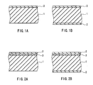
- FIG. 1A is a cross-sectional view showing a thermally conductive sheet according to an embodiment of the present invention.
- the thermally conductive sheet includes a solventless, adhesive elastic product layer 1 including, as the main component, an acrylic polymer into which a thermally conductive filler is mixed, and a cured thin film layer 2 in which a thermally conductive filler is mixed. That is, the cured thin film layer 2 is formed on the surface layer portion of one side of the solventless, adhesive elastic product layer 1.
- FIG. 1B shows an example in which the cured thin film layer 2 is formed on the surface layer portion of both sides of the solventless, adhesive elastic product layer 1.
- FIG. 2A is a cross-sectional view showing a thermally conductive sheet according to another embodiment of the present invention.
- the thermally conductive sheet includes a solventless, adhesive elastic product layer 1 including, as the main component, an acrylic polymer into which a thermally conductive filler is mixed, a sheet-like reinforcing material 3, and a cured thin film layer 2 that is provided as the surface layer of the sheet-like reinforcing material 3 and in which a thermally conductive filler is mixed.
- the sheet-like reinforcing material 3 is embedded in the solventless, adhesive elastic product layer 1.
- FIG. 2B is a cross-sectional view showing a thermally conductive sheet according to yet another embodiment of the present invention.
- the thermally conductive sheet includes a solventless, adhesive elastic product layer 1 including, as the main component, an acrylic polymer into which a thermally conductive filler is mixed, a sheet-like reinforcing material 3, and a cured thin film layer 2 that is provided as the surface layer of the sheet-like reinforcing material 3 and in which a thermally conductive filler is mixed, and a cured thin film layer 2 that is provided on the back side of the solventless, adhesive elastic product layer 1.
- a mesh structure made of, for example, polyester fiber, heat-resistant nylon fiber, aramid fiber or cotton fiber may be used as the sheet-like reinforcing material 3, it is preferable to use polyester fiber or heat-resistant nylon fiber from the view point of heat resistance.
- test sheet having a thickness of 0.5 mm was half-cut precisely into a square shape with a length of 25 mm and a width of 25 mm on a release sheet (note here that ''half-cut'' means only the test sheet formed of a thermally conductive sheet is cut without cutting the release sheet), using a cutting machine. Then, the test sheet was removed by fingers from the release sheet to be collected, and its dimensions were measured precisely to determine the elongation of the test sheet.
- test sheet having a thickness of 3.0 mm was used, and the hardness of the test sheet was measured according to JIS-K7312 (Physical testing methods for molded products of thermosetting polyurethane elastomers).
- Load refers to a compression force at which the sheet deforms when compressing the sheet.
- the purpose of measuring the load was to show the degree of deformation by compression of the sheet when the sheet included the cured thin film. A higher load indicates a higher resistance to deformation.
- a test sheet having a thickness of 3.0 mm was cut into a square shape with a length of 25 mm and a width of 25 mm, and the test sheet was then attached to the center of an aluminum plate (length: 27 mm, width: 27 mm, height: 3 mm) substantially accurately. Then, the test sheet was compressed using a MODEL 310N (compressing load measuring apparatus) manufactured by AIKOH Engineering Co. Ltd. that was provided with a load cell of 200 Kgf at a speed of 5 mm/min until the thickness of the test sheet became 50% of its original thickness, and the load was measured.
- MODEL 310N compressor load measuring apparatus
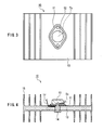
- the thermal resistance value was measured using a test sheet having a thickness of 0.5 mm.
- a thermal resistance value measuring apparatus 10 as shown in FIG. 3 (plan view taken from the top) and FIG. 4 (cross-sectional side view) was used.
- a sample 11 that had been punched into a predetermined shape was prepared, and the sample 11 was inserted and attached between a transistor 12 and a radiator 13 (15 denotes heat-radiating fins).
- the sample 11 was attached by tightening a M3 screw 14 with a predetermined torque (5 kg-cm) using a torque driver. After attaching the sample 11, a DC voltage of 10 V and a current of 2 A (20 W) was applied to the transistor 12.
- test sheet having a thickness of 0.5 mm was wrapped around a metal rod having a diameter of 4 mm, and the presence or absence of cracking was evaluated by determining whether the test sheet cracked.
- the adhesive strength was measured according to JIS-Z-0237 (Testing methods of pressure-sensitive adhesive tapes and sheets).
- This test measured the removability of the sheet when the sheet was deformed by compression.
- a test sheet having a thickness of 3.00 mm was cut into a square shape with a length of 50 mm and a width of 50 mm, and the test sheet then was attached to the center of an aluminum plate (length: 55 mm, width: 55 mm, height: 3 mm) substantially accurately.
- the test sheet was compressed using a MODEL 310N (compressing load measuring apparatus) manufactured by AIKOH Engineering Co. Ltd. that was provided with a load cell of 200 Kgf at a speed of 5 mm/min until the thickness of the test sheet became 50% (1.50 mm) of its original thickness. After releasing the load, the removability was evaluated by determining whether the aluminum plate could be removed manually.
- Urethane acrylate product name: ARONIX M-1200 manufactured by Toagosei Co., Ltd.
- ARONIX M-1200 manufactured by Toagosei Co., Ltd.
- this film is referred to as "film 1".
- a polyester film having a thickness of 0.10 mm that had been surface-treated with a fluorine compound was used as the release film.
- the sheet-like reinforcing material was formed by cutting a polyester fiber mesh (product name: C33 A2-100E11 with a thickness of 0.16 mm, manufactured by UNITIKA GLASS FIBER CO., LTD.) into a predetermined size in such a manner that no grease or dirt would adhere onto the surface of the mesh.
- a polyester fiber mesh product name: C33 A2-100E11 with a thickness of 0.16 mm, manufactured by UNITIKA GLASS FIBER CO., LTD.
- the thermally conductive sheet base material was placed on the reinforcing material, and a sheet of the release film was placed on the sheet base material so as to form a sandwich structure. Thereafter, the whole structure was heated and pressure molded at 120°C for 30 minutes, thereby forming sheets (A2) with thicknesses of 0.5 mm and 3.0 mm that contained the sheet-like reinforcing material and on one side of which the cured thin film layer was formed integrally.
- a sheet of the film 1 was placed on the sheet base material so as to form a sandwich structure. Thereafter, the whole structure was heated and pressure molded at 120°C for 30 minutes, thereby forming sheets (A3) with thicknesses of 0.5 mm and 3.0 mm, on both sides of which the cured thin film layer was formed integrally.
- the thermally conductive sheet base material was placed on the reinforcing material, and a sheet of the film 1 was placed on the sheet base material so as to form a sandwich structure. Thereafter, the whole structure was heated and pressure molded at 120°C for 30 minutes, thereby forming sheets (A4) with thicknesses of 0.5 mm and 3.0 mm that contained the sheet-like reinforcing material and on both sides of which the cured thin film layer was formed integrally.
- Table 1 shows the results on the above-described sheets.
- Table 1 Sample No. A1 A2 A3 A4 B1 Cured thin film one side only one side only both sides both sides not provided Sheet-like reinforcing material not provided provided not provided provided not provided not provided Elongation (mm) 0 0 0 0 0.4 Hardness (Asker C) 25 37 32 40 20 Load (Kgf) 40 50 50 55 25 Thermal resistance value (°C/W) 0.84 0.81 0.90 0.93 0.80
- the sheets on the surface of which the cured thin film layer was formed integrally had good handleability.
- the elongation of the sheets at the time of removal from the release film could be reduced significantly by providing the reinforcing layer on the surface.
- the cured thin film layer was formed from a mixture of a modified acrylate and an acrylic monomer, or a mixture of a modified acrylate and an acrylic polymer, the elongation of the sheet at the time of removal could be reduced to nearly "0". Additionally, the sheet did not crack when it was bent.
- the thermally conductive sheet base material was formed in the same manner as Test ⁇ 1.
- Urethane acrylate (product name: ARONIX M-1200 manufactured by Toagosei Co., Ltd.) was applied uniformly as a thin film with a thickness of 2 ⁇ m using a coating machine onto a polyester film having a thickness of 0.10 mm that had been subjected to a mold release treatment with fluorine, thereby forming a film 2.
- Epoxy acrylate (product name: 8101 manufactured by Japan U-PiCA Company, Ltd.) was applied uniformly as a thin film with a thickness of 2 ⁇ m using a coating machine onto a polyester film having a thickness of 0.10 mm that had been subjected to a mold release treatment with fluorine, thereby forming a film 3.
- Polyester acrylate (product name: M-8060 manufactured by Toagosei Co., Ltd.) was applied uniformly as a thin film with a thickness of 2 ⁇ m using a coating machine onto a polyester film having a thickness of 0.10 mm that had been subjected to a mold release treatment with fluorine, thereby forming a film 4.
- urethane acrylate product name: ARONIXM-1200 manufactured by Toagosei Co., Ltd.
- phenoxy acrylate manufactured by OSAKA ORGANIC CHEMICAL INDUSTRY LTD.
- epoxy acrylate product name: 8101 manufactured by Japan U-PiCA Company, Ltd.
- phenoxy acrylate manufactured by OSAKA ORGANIC CHEMICAL INDUSTRY LTD.
- polyester acrylate product name: M-8060 manufactured by Toagosei Co., Ltd.
- phenoxy acrylate manufactured by OSAKA ORGANIC CHEMICAL INDUSTRY LTD.
- an acrylic polymer product name: JDX-P1020 manufactured by JOHNSON POLYMER CORPORATION
- phenoxy acrylate manufactured by OSAKA ORGANIC CHEMICAL INDUSTRY LTD.
- an acrylic polymer product name: JDX-P1020 manufactured by JOHNSON POLYMER CORPORATION
- urethane acrylate product name: ARONIX M-1200 manufactured by manufactured by Toagosei Co., Ltd.
- a polyester film with a thickness of 0.10 mm that had been surface-treated with a fluorine compound was used as the release film.
- a sheet of the release film was placed on the sheet base material so as to form a sandwich structure. Thereafter, the whole structure was heated and pressure molded at 120°C for 30 minutes, followed by removing the top and bottom films, thereby forming sheets (A5) with thicknesses of 0.5 mm and 3.0 mm, on one side of which the cured thin film layer was formed integrally.
- a sheet of the release film was placed on the sheet base material so as to form a sandwich structure. Thereafter, the whole structure was heated and pressure molded at 120°C for 30 minutes, followed by removing the top and bottom films, thereby forming sheets (A6) with thicknesses of 0.5 mm and 3.0 mm, on one side of which the cured thin film layer was formed integrally.
- a sheet of the release film was placed on the sheet base material so as to form a sandwich structure. Thereafter, the whole structure was heated and pressure molded at 120°C for 30 minutes, followed by removing the top and bottom films, thereby forming sheets (A7) with thicknesses of 0.5 mm and 3.0 mm, on one side of which the cured thin film layer was formed integrally.
- a sheet of the release film was placed on the sheet base material so as to form a sandwich structure. Thereafter, the whole structure was heated and pressure molded at 120°C for 30 minutes, followed by removing the top and bottom films, thereby forming sheets (A8) with thicknesses of 0.5 mm and 3.0 mm, on one side of which the cured thin film layer was formed integrally.
- a sheet of the release film was placed on the sheet base material so as to form a sandwich structure. Thereafter, the whole structure was heated and pressure molded at 120°C for 30 minutes, followed by removing the top and bottom films, thereby forming sheets (A9) with thicknesses of 0.5 mm and 3.0 mm, on one side of which the cured thin film layer was formed integrally.
- a sheet of the release film was placed on the sheet base material so as to form a sandwich structure. Thereafter, the whole structure was heated and pressure molded at 120°C for 30 minutes, followed by removing the top and bottom films, thereby forming sheets (A10) with thicknesses of 0.5 mm and 3.0 mm, on one side of which the cured thin film layer was formed integrally.
- a sheet of the release film was placed on the sheet base material so as to form a sandwich structure. Thereafter, the whole structure was heated and pressure molded at 120°C for 30 minutes, followed by removing the top and bottom films, thereby forming sheets (A11) with thicknesses of 0.5 mm and 3.0 mm, on one side of which the cured thin film layer was formed integrally.
- a sheet of the release film was placed on the sheet base material so as to form a sandwich structure. Thereafter, the whole structure was heated and pressure molded at 120°C for 30 minutes, followed by removing the top and bottom films, thereby forming sheets (A12) with thicknesses of 0.5 mm and 3.0 mm, on one side of which the cured thin film layer was formed integrally.
- the cured thin film was formed only from a modified acrylate. Since a modified acrylate includes a large number of functional groups in its molecules, the cross-linking density of the cured thin film layer was higher and the cured thin film cracked easily. However, in the case of the sample Nos. A9 to A12 of Working Example 9 to Working Example 12, an acrylic monomer or an acrylic rubber was added to the modified acrylate to decrease the cross-linking density of the cured thin film layer, so that the cured thin film was imparted with flexibility and thus became more difficult to crack.
- the sample No. B2 of Comparative Example 2 was an example in which the sample was formed only from the thermally conductive sheet base material.
- the sheet of the sample No. B2 of Comparative Example 2 was not desirable since it was elongated and deformed.
- the sheets of the sample Nos. A9 to A12 of Working Example 9 to Working Example 12 deformed in the thickness direction, but not in the longitudinal direction, exhibiting good form stability.
- the thermally conductive sheet base material was formed in the same manner as Test ⁇ 1.
- film 11 to film 14 below were formed.
- urethane acrylate product name: ARONIX M-1200 manufactured by Toagosei Co., Ltd.
- aluminum oxide product name: AL-43L manufactured by SHOWA DENKO K.K.
- iron black 1 part by mass of a curing agent (chemical name: t-Amyl peroxy-2-ethylhexanoate manufactured by Kayaku Akzo Corporation) were mixed sufficiently in a mixer. Then, the mixture was applied uniformly as a thin film with a thickness of 2 ⁇ m using a coating machine onto a polyester film having a thickness of 0.10 mm that had been subjected to a mold release treatment with fluorine, thereby forming a film 11.
- polyester acrylate product name: M-6100 manufactured by Toagosei Co., Ltd.
- aluminum oxide product name: AL-43L manufactured by SHOWA DENKO K.K.
- iron black 1 part by mass of a curing agent (chemical name: t-Amyl peroxy-2-ethylhexanoate manufactured by Kayaku Akzo Corporation) were mixed sufficiently in a mixer. Then, the mixture was applied uniformly as a thin film with a thickness of 2 ⁇ m using a coating machine onto a polyester film having a thickness of 0.10 mm that had been subjected to a mold release treatment with fluorine, thereby forming a film 12.
- the mixture was applied uniformly as a thin film with a thickness of 2 ⁇ m using a coating machine onto a polyester film having a thickness of 0.10 mm that had been subjected to a mold release treatment with fluorine, thereby forming a film 13.
- the mixture was applied uniformly as a thin film with a thickness of 2 ⁇ m using a coating machine onto a polyester film having a thickness of 0.10 mm that had been subjected to a mold release treatment with fluorine, thereby forming a film 14.
- a polyester film having a thickness of 0.10 mm that had been surface-treated with a fluorine compound was used as a film 15.
- the sheet-like reinforcing material was formed by cutting a polyester fiber mesh (product name: C33 A2-100E 11 with a thickness of 0.16 mm, manufactured by UNITIKA GLASS FIBER CO., LTD.) into a predetermined size in such a manner that no grease or dirt would adhere onto the surface of the mesh.
- a polyester fiber mesh product name: C33 A2-100E 11 with a thickness of 0.16 mm, manufactured by UNITIKA GLASS FIBER CO., LTD.
- a polyester film having a thickness of 0.10 mm that had been surface-treated with a fluorine compound was used as the release film.
- the thermally conductive sheet base material was placed on the reinforcing material, and a sheet of the release film was placed further on the sheet base material so as to form a sandwich structure. Thereafter, the whole structure was heated and pressure molded at 120°C for 30 minutes, followed by removing the top and bottom films, thereby forming sheets (A13) with thicknesses of 0.5 mm and 3.0 mm, on one side of which the thermally conductive, cured thin film layer was formed integrally.
- a sheet of the release film was placed on the sheet base material so as to form a sandwich structure. Thereafter, the whole structure was heated and pressure molded at 120°C for 30 minutes, followed by removing the top and bottom films, thereby forming sheets (A14) with thicknesses of 0.5 mm and 3.0 mm, on one side of which the thermally conductive, cured thin film layer was formed integrally.
- the thermally conductive sheet base material was placed on the reinforcing material, and a sheet of the release film was placed further on the sheet base material so as to form a sandwich structure. Thereafter, the whole structure was heated and pressure molded at 120°C for 30 minutes, followed by removing the top and bottom films, thereby forming sheets (A15) with thicknesses of 0.5 mm and 3.0 mm, on one side of which the thermally conductive, cured thin film layer was formed integrally.
- a sheet of the release film was placed on the sheet base material so as to form a sandwich structure. Thereafter, the whole structure was heated and pressure molded at 120°C for 30 minutes, followed by removing the top and bottom films, thereby forming sheets (A16) with thicknesses of 0.5 mm and 3.0 mm, on one side of which the thermally conductive, cured thin film layer was formed integrally.
- the thermally conductive sheet base material was placed on the reinforcing material, and a sheet of the release film was placed further on the sheet base material so as to form a sandwich structure. Thereafter, the whole structure was heated and pressure molded at 120°C for 30 minutes, followed by removing the top and bottom films, thereby forming sheets (A17) with thicknesses of 0.5 mm and 3.0 mm, on one side of which the thermally conductive, cured thin film layer was formed integrally.
- a sheet of the release film was placed on the sheet base material so as to form a sandwich structure. Thereafter, the whole structure was heated and pressure molded at 120°C for 30 minutes, followed by removing the top and bottom films, thereby forming sheets (A18) with thicknesses of 0.5 mm and 3.0 mm, on one side of which the thermally conductive, cured thin film layer was formed integrally.
- the thermally conductive sheet base material was placed on the reinforcing material, and a sheet of the release film was placed further on the sheet base material so as to form a sandwich structure. Thereafter, the whole structure was heated and pressure molded at 120°C for 30 minutes, followed by removing the top and bottom films, thereby forming sheets (A19) with thicknesses of 0.5 mm and 3.0 mm, on one side of which the thermally conductive, cured thin film layer was formed integrally.
- a sheet of the release film was placed on the sheet base material so as to form a sandwich structure. Thereafter, the whole structure was heated and pressure molded at 120°C for 30 minutes, followed by removing the top and bottom films, thereby forming sheets (A20) with thicknesses of 0.5 mm and 3.0 mm, on one side of which the thermally conductive, cured thin film layer was formed integrally.
- the thermally conductive sheet base material was placed on the reinforcing material, and a sheet of the release film was placed further on the sheet base material so as to form a sandwich structure. Thereafter, the whole structure was heated and pressure molded at 120°C for 30 minutes, followed by removing the top and bottom films, thereby forming sheets (B3) with thicknesses of 0.5 mm and 3.0 mm. ,
- a sheet of the release film was placed on the sheet base material so as to form a sandwich structure. Thereafter, the whole structure was heated and pressure molded at 120°C for 30 minutes, followed by removing the top and bottom films, thereby forming sheets (B4) with thicknesses of 0.5 mm and 3.0 mm.
- a sheet of the release film was placed further on the sheet base material so as to form a sandwich structure. Thereafter, the whole structure was heated and pressure molded at 120°C for 30 minutes, followed by removing the top and bottom films, thereby forming sheets (B5) with thicknesses of 0.5 mm and 3.0 mm.
- Tables 3 and 4 show the results on the above-described sheets.
- Table 3 Sample No. A13 A14 A15 A16 A17 A18 A19 A20 Sheet-like reinforcing material provided not provided provided not provided provided not provided Adhesive strength (g/25 mm) 0 0 0 0 0 0 0 0 0 0 Thermal resistance value (°C/W) 0.92 0.99 0.92 0.88 0.90 0.86 0.90 0.86 Removability easy easy easy easy easy easy easy easy easy easy easy easy easy easy easy Table 4 Sample No. B3 B4 B5 B6 Sheet-like reinforcing material provided not provided provided not provided not provided Adhesive strength (g/25 mm) 12 12 0 0 Thermal resistance value (°C /W) 0.38 0.36 0.94 0.92 Removability difficult difficult easy easy easy easy easy easy.
- the adhesive strength of the sample Nos. A13 to 20 of Working Examples 13 to 20 could be reduced to nearly "0" by forming the cured thin film layer. This made it possible to separate a heat-generating electronic component and a radiator readily, even after inserting the thermally conductive film between them. Furthermore, the thermal resistance value (°C/W) was improved even further by providing the cured thin film layer with thermal conductivity.
Abstract

Description
- The present invention relates to thermally conductive sheets that are used when mounting electronic components generating a large amount of heat to the cooling portions of heat sinks, radiators and the like, and to methods for producing such thermally conductive sheets.
- Thermally conductive materials are used when mounting electronic components generating a large amount of heat, such as power transistors and power modules (hereinafter, referred to as "heat-generating electronic components"), to heat sinks, radiators and the like for eliminating gaps between the components and conducting the heat that is generated by the heat-generating electronic components to the heat sinks, the radiators and the like efficiently. As such thermally conductive materials, there have been proposed, for example, heat-radiating grease and heat-radiating compounds that are formed by mixing liquid silicone with a metal oxide, and thermally conductive heat-radiating members that are fabricated by mixing silicone rubber with a metal oxide and molding it into a sheet (JP H9-207275A and JP H10-183110A).
- However, the use of grease, compounds and heat-radiating sheets that are made of liquid silicone resin and silicone rubber has been avoided recently, since low molecular weight siloxane is volatilized when the heat-radiating members are heated by the heat that is generated by operating the heat-generating electronic components, and the low molecular weight volatile silicone that is filled inside the electronic devices tends to cause a so-called "silicone trouble". Therefore, heat-radiating members that are made of materials other than silicone increasingly have been used recently.
- Therefore, with the foregoing in mind, it is an object of the present invention to provide a thermally conductive sheet having high thermal conductivity, good dimensional stability, softness, excellent loading characteristics and resistance to cracking, by using a polymer compound that does not create the possibility that a low molecular weight substance such as a monomer or an oligomer will bleed out, and a method for producing the thermally conductive sheet.
- A thermally conductive sheet according to the present invention is a thermally conductive sheet including, as a main component, an acrylic polymer into which a thermally conductive filler is mixed, wherein an inner layer or one side of the sheet is a solventless, adhesive elastic product, and a cured thin film layer is formed integrally with a surface layer portion on at least one selected from top and bottom surfaces of the sheet.
- A method for producing a thermally conductive sheet according to the present invention is a method for producing a thermally conductive sheet including, as a main component, an acrylic polymer into which a thermally conductive filler is mixed, the method including the steps of: forming a cured thin film material layer wherein a material for a thermally conductive, cured thin film layer is applied uniformly as a thin film onto a surface of at least one selected from a top release film and a bottom release film; providing, when one of the films includes the cured thin film material layer, a release film as the other film; supplying, between the top film and the bottom film, a sheet base material including, as a main component, an acrylic polymer into which a thermally conductive filler is mixed, and molding the sheet base material into a sheet having a predetermined thickness; and thereafter curing only a surface layer portion of the sheet and then removing the films, thereby producing a thermally conductive sheet wherein an inner layer or one side of the sheet is a solventless, adhesive elastic product, and a cured thin film layer is formed integrally with a surface layer portion on at least one selected from the top and bottom surfaces of the sheet.
- FIG. 1A is a cross-sectional view showing an embodiment of a thermally conductive sheet according to the present invention, and shows an example in which a cured thin film layer is formed on one side of a solventless, adhesive elastic product layer.
- FIG. 1B shows an example in which the cured thin film layer is formed on both sides of the adhesive elastic product layer.
- FIG. 2A is a cross-sectional view showing a thermally conductive sheet according to another embodiment of the present invention, and shows an example in which a sheet-like reinforcing material is embedded inside the surface of the solventless, adhesive elastic product layer, and the cured thin film layer is formed as the surface layer of the adhesive elastic product layer.
- FIG. 2B shows an example in which the cured thin film layer is formed in both surfaces of the adhesive elastic product layer.
- FIG. 3 is a plan view illustrating the method for measuring a thermal resistance value in the working examples and comparative examples of the present invention.
- FIG. 4 is a cross-sectional side view illustrating the same method.
- Hereinafter, the present invention will be described by way of illustrative embodiments with reference to the drawings.
- The thermally conductive sheet of the present invention includes, as the main component, an acrylic polymer into which a thermally conductive filler is mixed. Here, "main component" refers to a component that constitutes at least 20 mass% of 100 mass% of the total organic components. Using an acrylic polymer as the base resin can eliminate the possibility that a low molecular weight substance such as a monomer or an oligomer will bleed out. This is a property inherent to acrylic polymers.
- Furthermore, an inner layer or one side of the thermally conductive sheet of the present invention is a solventless, adhesive elastic product. It should be noted here that the term "solventless" as used herein means that the elastic product is formed without actively using an organic solvent. Thus, the elastic product may contain moisture in the air adsorbed thereto. Accordingly, when attaching the thermally conductive sheet to a heat-generating product such as an electronic component, the thermally conductive sheet freely can change its shape in the thickness direction so as to be attached to the heat-generating product without any gap, thus achieving high heat conductivity and high heat radiation. A cured thin film layer is formed integrally with a surface layer portion on at least one selected from the top and bottom surfaces of the sheet. Accordingly, while the inner layer or one side of the thermally conductive sheet is soft, like dough, the thermally conductive sheet is easy to handle because it has a hard thin film layer as the surface layer.
- The method for producing a thermally conductive sheet according to the present invention provides a thermally conductive sheet of the present invention by attaching a thin layer of the material for a thermally conductive, cured thin film layer onto the surface layer of a soft sheet base material by using a so-called transfer method, and then curing only the surface layer of the above-described sheet. That is, the thermally conductive sheet is produced by applying the material for a thermally conductive, cured thin film layer uniformly as a thin film onto a release resin film, supplying, onto the surface on which the above-mentioned material has been applied, a sheet base material including, as the main component, an acrylic polymer into which a thermally conductive filler is mixed, placing the release resin film or the release resin film onto which the thermally conductive, cured thin film layer material is applied uniformly as a thin film, over the sheet base material, and molding the sheet base material into a sheet having a predetermined thickness, and thereafter curing only the surface layer portion of the above-described sheet, and then removing the above-described films.
- It is preferable that the cured thin film layer that is formed integrally with one or both sides of the thermally conductive sheet, or the thermally conductive, cured thin film layer has a thickness in the range from 0.001 mm to 0.50 mm. It is preferable that the thermally conductive sheet has an overall thickness of 0.10 mm to 10 mm. Furthermore, a sheet-like reinforcing material may be embedded near the surface layer portion of one of the top and bottom surfaces, and it is preferable that the thickness of the thermally conductive sheet is larger than that of the sheet-like reinforcing material.
- In the following, various materials and the manufacturing steps will be described.
- (1) Thermally conductive sheet base material including, as the main component, an acrylic polymer into which thermally conductive filler is mixed.
As the acrylic polymer that is the main component of the thermally conductive sheet base material, it is preferable to use, for example, a single oligomer or polymer having at least two acrylic groups or methacrylic groups as the functional groups, a mixture of an oligomer and a monomer having at least two acrylic groups or methacrylic groups as the functional groups, a mixture of a polymer and a monomer having acrylic groups or methacrylic groups as the functional groups, or a mixture of a polymer, an oligomer and a monomer having at least two acrylic groups or methacrylic groups as the functional groups.
It is preferable that the thermally conductive sheet base material is a mixture in which 50 parts by mass to 3000 parts by mass of a thermally conductive substance per 100 parts by mass of an acrylic polymer is mixed, and the filled amount of the thermally conductive substance is preferably 500 parts by mass to 2500 parts by mass. In that case, the viscosity of the mixture is preferably in the range from 10000 to 3000000 cP. - (2) Thermally conductive filler
The thermally conductive filler that is mixed in the thermally conductive sheet base material of the present invention may be, for example, a powdered, fibrous, acicular, flakey or spherical filler that is made of one or more materials selected from the group consisting of metals such as aluminum, copper and silver, metal oxides such as alumina, magnesia and silica, and aluminum nitride, boron nitride, silicon nitride and the like. In the present invention, it is preferable to use metal oxides. The thermally conductive filler may be surface-treated with a known silane coupling agent that is selected in accordance with its properties. Furthermore, the above-described filler, when in the form of particles, preferably has an average particle size of 0.2 to 100 µm, and it is preferable that the size of the filler in other forms is in a range that is substantially equivalent to this particle size. - (3) Material for cured thin film layer
The material for the cured thin film layer of the present invention may be an oligomer or a polymer that has at least two acrylic groups or methacrylic groups, and examples include urethane acrylate, epoxy acrylate and polyester acrylate. Commercially available products of these may be used suitably, either alone or as a mixture of two or more of them. The material for the cured thin film layer is solventless. The viscosity of the material is preferably 50 to 20000 cP, more preferably in the range from 1000 to 10000 cP. - (4) Film provided with cured thin film layer
In the production of the cured thin film layer, the material for the cured thin film layer is applied uniformly as a thin film onto a resin film whose surface has been subjected to a mold release treatment in advance, by knife coating, bar coating, gravure coating or multistage roll coating, for example, thereby forming a film on the resin film. - (5) Integration by transferring
In the present invention, it is preferable to use a method that includes filling a thermally conductive sheet base material into the surface film on which the material of a cured thin film layer is formed uniformly, removing the film after curing the base material, and integrating the cured thin film layer material with the surface of the thermally conductive sheet by transferring. Examples of the molding method include press molding, coating molding and calendaring molding, and any of these molding methods may be selected freely in accordance with the degree of viscosity of the compound. - (6) Sheet-like reinforcing material
The sheet-like reinforcing material is contained in the inner layer of the thermally conductive sheet for reinforcing the sheet to prevent a significant deformation. Examples of the sheet-like reinforcing material include a woven or nonwoven fabric of, for example, plain weave, twill weave, satin weave, leno weave or mock leno weave of inorganic fiber such as glass fiber and carbon fiber, or synthetic resin fiber such as polyester fiber and nylon fiber. The sheet-like reinforcing material may be surface-treated with a known silane coupling agent that is selected in accordance with its properties. It is preferable that the sheet-like reinforcing material of the present invention is contained completely in the inner layer or one side of the thermally conductive sheet so as not to be exposed from the inner layer or one side. If the reinforcing material is exposed on the surface, then the surface of the thermally conductive sheet becomes uneven, leading to an insufficient adhesion between the heat-generating electronic components and a heat sink, a radiator or the like and thus causing gaps between the components. Accordingly, it is difficult to conduct the heat that is generated by the heat-generating electronic components to the heat sink, the radiator or the like efficiently. - (7) Material for thermally conductive, cured thin film layer
The material for the thermally conductive, cured thin film layer according to a preferred embodiment of the present invention may be an oligomer or polymer that has at least two acrylic groups or methacrylic groups, and examples include urethane acrylate, epoxy acrylate and polyester acrylate. Commercially available products of these may be used suitably, either alone or as a mixture of two or more of them. Further, the thermally conductive substance that is mixed in the cured thin film layer may be, for example, a powdered, fibrous, acicular, flakey or spherical filler that is made of one or more materials selected from the group consisting of metals such as aluminum, copper and silver, metal oxides such as alumina, magnesia and silica, and aluminum nitride, boron nitride, silicon nitride and the like. In the present invention, the particle size of the metal oxides is preferably 0.2 to 8 µm. The thermally conductive substance may be surface-treated with a known silane coupling agent that is selected in accordance with its properties. The material for the cured thin film layer is solventless. The viscosity of the material is preferably 50 to 20000 cP, more preferably in the range from 1000 to 10000 cP. - (8) Film provided with thermally conductive, cured thin film layer
The thermally conductive, cured thin film layer is formed by applying the material for the thermally conductive cured thin film layer uniformly as a thin film onto a resin film that has been subjected to a mold release treatment, by knife coating, bar coating, gravure coating or multistage roll coating, for example, thereby forming a film on the resin film. Then, it is preferable to perform a method that includes filling, into a surface on which the material for the cured thin film layer is formed uniformly, a sheet base material including, as the main component, an acrylic polymer into which a thermally conductive filler is mixed, thereafter curing the mixture and then removing the film that has been subjected to a mold release treatment, and integrating the thermally conductive, cured thin film layer material with the surface of the thermally conductive sheet by transferring. Examples of the molding method include press molding, coating molding and calendaring, and any of these molding methods may be selected freely in accordance with the degree of viscosity of the compound. In any case, it is preferable to use, for example, a polyester film or a polypropylene film that has been surface-treated with a fluorine compound or a silicone compound, as the film on which the cured thin film layer is placed. - (9) Release film
The release film may be selected suitably from, for example, a polyester film, a polypropylene film and a fluorine film that have been surface-treated with a fluorine compound or a silicone compound. - (10) Protective film
It is preferable that the other side of the thermally conductive sheet that does not have the cured thin film layer is covered with, for example, an embossed protective film. An embossed film is a film whose surface is provided with protrusions and depressions. The density of the roughness may be adjusted appropriately in accordance with the difference in adhesive strength with the thermally conductive sheet. The protective film is like a sheet provided on a poultice. While any resin film may be used as the material for the protective film, it is preferable to use a film made of polyethylene resin or polypropylene resin having a thickness of about 30 µm to about 80 µm. It is preferable that the embossed surface has a level difference of at least 120 µm. - The present invention provides a thermally conductive sheet including, as the main component, an acrylic polymer into which a thermally conductive filler is mixed, wherein the inner surface or one side of the above-described sheet is a solventless, adhesive elastic product, and a cured thin film layer is formed integrally with the surface layer portion of at least one selected from the top and bottom surfaces of the above-described sheet. Accordingly, it is possible to provide a thermally conductive sheet that does not provide the possibility that a low molecular weight substance such as a monomer or an oligomer will bleed out, while having high thermal conductivity, good dimensional stability, softness, excellent loading characteristics and resistance to cracking, and a method for producing such a thermally conductive sheet. In addition, by molding a cured thin film layer that has been cured or embedding a sheet-like reinforcing material on the surface layer portion of at least one side of the thermally conductive sheet, the elongation of the product at the time of removal from a release sheet can be reduced significantly, resulting in better handleability. Moreover, by setting the ratio between a modified acrylate and an acrylic monomer, or the ratio between a modified acrylate and an acrylic polymer to a suitable ratio, the sheet will not crack when it is bent.
- FIG. 1A is a cross-sectional view showing a thermally conductive sheet according to an embodiment of the present invention. As shown in FIG. 1A, the thermally conductive sheet includes a solventless, adhesive elastic product layer 1 including, as the main component, an acrylic polymer into which a thermally conductive filler is mixed, and a cured
thin film layer 2 in which a thermally conductive filler is mixed. That is, the curedthin film layer 2 is formed on the surface layer portion of one side of the solventless, adhesive elastic product layer 1. FIG. 1B shows an example in which the curedthin film layer 2 is formed on the surface layer portion of both sides of the solventless, adhesive elastic product layer 1. - FIG. 2A is a cross-sectional view showing a thermally conductive sheet according to another embodiment of the present invention. As shown in FIG. 2A, the thermally conductive sheet includes a solventless, adhesive elastic product layer 1 including, as the main component, an acrylic polymer into which a thermally conductive filler is mixed, a sheet-like reinforcing
material 3, and a curedthin film layer 2 that is provided as the surface layer of the sheet-like reinforcingmaterial 3 and in which a thermally conductive filler is mixed. The sheet-like reinforcingmaterial 3 is embedded in the solventless, adhesive elastic product layer 1. - FIG. 2B is a cross-sectional view showing a thermally conductive sheet according to yet another embodiment of the present invention. As shown in FIG. 2B, the thermally conductive sheet includes a solventless, adhesive elastic product layer 1 including, as the main component, an acrylic polymer into which a thermally conductive filler is mixed, a sheet-like reinforcing
material 3, and a curedthin film layer 2 that is provided as the surface layer of the sheet-like reinforcingmaterial 3 and in which a thermally conductive filler is mixed, and a curedthin film layer 2 that is provided on the back side of the solventless, adhesive elastic product layer 1. While a mesh structure made of, for example, polyester fiber, heat-resistant nylon fiber, aramid fiber or cotton fiber may be used as the sheet-like reinforcingmaterial 3, it is preferable to use polyester fiber or heat-resistant nylon fiber from the view point of heat resistance. - In the following, the measurement methods of various tests that were carried out in the working examples and comparative examples of the present invention will be described.
- In this measurement, the elongation (degree of deformation) in the longitudinal direction of the sheet was measured. A test sheet having a thickness of 0.5 mm was half-cut precisely into a square shape with a length of 25 mm and a width of 25 mm on a release sheet (note here that ''half-cut'' means only the test sheet formed of a thermally conductive sheet is cut without cutting the release sheet), using a cutting machine. Then, the test sheet was removed by fingers from the release sheet to be collected, and its dimensions were measured precisely to determine the elongation of the test sheet.
- A test sheet having a thickness of 3.0 mm was used, and the hardness of the test sheet was measured according to JIS-K7312 (Physical testing methods for molded products of thermosetting polyurethane elastomers).
- "Load" as used herein refers to a compression force at which the sheet deforms when compressing the sheet. The purpose of measuring the load was to show the degree of deformation by compression of the sheet when the sheet included the cured thin film. A higher load indicates a higher resistance to deformation. In this measurement, a test sheet having a thickness of 3.0 mm was cut into a square shape with a length of 25 mm and a width of 25 mm, and the test sheet was then attached to the center of an aluminum plate (length: 27 mm, width: 27 mm, height: 3 mm) substantially accurately. Then, the test sheet was compressed using a MODEL 310N (compressing load measuring apparatus) manufactured by AIKOH Engineering Co. Ltd. that was provided with a load cell of 200 Kgf at a speed of 5 mm/min until the thickness of the test sheet became 50% of its original thickness, and the load was measured.
- The thermal resistance value was measured using a test sheet having a thickness of 0.5 mm. A thermal resistance
value measuring apparatus 10 as shown in FIG. 3 (plan view taken from the top) and FIG. 4 (cross-sectional side view) was used. First, asample 11 that had been punched into a predetermined shape was prepared, and thesample 11 was inserted and attached between atransistor 12 and a radiator 13 (15 denotes heat-radiating fins). Thesample 11 was attached by tightening aM3 screw 14 with a predetermined torque (5 kg-cm) using a torque driver. After attaching thesample 11, a DC voltage of 10 V and a current of 2 A (20 W) was applied to thetransistor 12. Three minutes later, the transistor temperature To and the radiator temperature Tf were measured by temperature sensors provided at predetermined positions. Then, the thermal resistance value was calculated from the temperatures at the two points, using an equation. Specifically, the thermal resistance value was calculated using a transistor: 2SC2245 manufactured by FUJI ELECTRIC HOLDINGS CO., LTD., a radiator: 40CH104L-90-K manufactured by Ryosan Co., Ltd., and temperature sensors: 2SC1-OHK300 manufactured by CHINO CORPORATION, at ambient temperature and humidity: 25°C, 60% RH, by the following thermal resistance calculation equation:
- θ : thermal resistance value (°C/W)
- Tc: transistor temperature (°C)
- Tf: radiator temperature (°C)
- PC: power applied to the transistor
- A test sheet having a thickness of 0.5 mm was wrapped around a metal rod having a diameter of 4 mm, and the presence or absence of cracking was evaluated by determining whether the test sheet cracked.
- The adhesive strength was measured according to JIS-Z-0237 (Testing methods of pressure-sensitive adhesive tapes and sheets).
- This test measured the removability of the sheet when the sheet was deformed by compression. A test sheet having a thickness of 3.00 mm was cut into a square shape with a length of 50 mm and a width of 50 mm, and the test sheet then was attached to the center of an aluminum plate (length: 55 mm, width: 55 mm, height: 3 mm) substantially accurately. Then, the test sheet was compressed using a MODEL 310N (compressing load measuring apparatus) manufactured by AIKOH Engineering Co. Ltd. that was provided with a load cell of 200 Kgf at a speed of 5 mm/min until the thickness of the test sheet became 50% (1.50 mm) of its original thickness. After releasing the load, the removability was evaluated by determining whether the aluminum plate could be removed manually.
- In the following, the working examples and the comparative examples will be described.
- 100 parts by mass of an acrylic polymer (product name: JDX-P1020 manufactured by JOHNSON POLYMER CORPORATION) and 20 parts by mass of an acrylic monomer (product name: FA-511A manufactured by Hitachi Chemical Co., Ltd.) were kneaded in a mixer, together with 300 parts by mass of aluminum oxide (product name: AS30 manufactured by SHOWA DENKO K.K.) and 2 parts by mass of iron black, 1.0 part by mass of a curing agent (chemical name: t-Amyl peroxy-2-ethylhexanoate manufactured by Kayaku Akzo Corporation), thereby forming a thermally conductive sheet base material. The thermal conductivity was 0.8 W/m-K.
- Urethane acrylate (product name: ARONIX M-1200 manufactured by Toagosei Co., Ltd.) as the material for the cured thin film layer was applied uniformly as a thin film with a thickness of 2 µm using a coating machine onto a polyester film with a thickness of 0.10 mm that had been subjected to a mold release treatment with fluorine, thereby forming a film provided with the cured thin film layer. Hereinafter, this film is referred to as "film 1".
- A polyester film having a thickness of 0.10 mm that had been surface-treated with a fluorine compound was used as the release film.
- The sheet-like reinforcing material was formed by cutting a polyester fiber mesh (product name: C33 A2-100E11 with a thickness of 0.16 mm, manufactured by UNITIKA GLASS FIBER CO., LTD.) into a predetermined size in such a manner that no grease or dirt would adhere onto the surface of the mesh.
- After placing the thermally conductive sheet base material on a sheet of the film 1, a sheet of the release film was placed on the sheet base material so as to form a sandwich structure. Thereafter, the whole structure was heated and pressure molded at 120°C for 30 minutes, thereby forming sheets (A1) with thicknesses of 0.5 mm and 3.0 mm, on one side of which the cured thin film layer was formed integrally.
- After placing the sheet-like reinforcing material on a sheet of the film 1, the thermally conductive sheet base material was placed on the reinforcing material, and a sheet of the release film was placed on the sheet base material so as to form a sandwich structure. Thereafter, the whole structure was heated and pressure molded at 120°C for 30 minutes, thereby forming sheets (A2) with thicknesses of 0.5 mm and 3.0 mm that contained the sheet-like reinforcing material and on one side of which the cured thin film layer was formed integrally.
- After placing the thermally conductive sheet base material on a sheet of the film 1, a sheet of the film 1 was placed on the sheet base material so as to form a sandwich structure. Thereafter, the whole structure was heated and pressure molded at 120°C for 30 minutes, thereby forming sheets (A3) with thicknesses of 0.5 mm and 3.0 mm, on both sides of which the cured thin film layer was formed integrally.
- After placing the sheet-like reinforcing material on a sheet of the film 1, the thermally conductive sheet base material was placed on the reinforcing material, and a sheet of the film 1 was placed on the sheet base material so as to form a sandwich structure. Thereafter, the whole structure was heated and pressure molded at 120°C for 30 minutes, thereby forming sheets (A4) with thicknesses of 0.5 mm and 3.0 mm that contained the sheet-like reinforcing material and on both sides of which the cured thin film layer was formed integrally.
- After placing the thermally conductive sheet base material on a sheet of the release film, a sheet of the same release film was placed on the sheet base material so as to form a sandwich structure. Thereafter, the whole structure was heated and pressure molded at 120°C for 30 minutes, thereby forming sheets (B1) with thicknesses of 0.5 mm and 3.0 mm.
- Table 1 shows the results on the above-described sheets.
Table 1 Sample No. A1 A2 A3 A4 B1 Cured thin film one side only one side only both sides both sides not provided Sheet-like reinforcing material not provided provided not provided provided not provided Elongation (mm) 0 0 0 0 0.4 Hardness (Asker C) 25 37 32 40 20 Load (Kgf) 40 50 50 55 25 Thermal resistance value (°C/W) 0.84 0.81 0.90 0.93 0.80 - As is clearly seen from Table 1, the sheets on the surface of which the cured thin film layer was formed integrally had good handleability. In addition, the elongation of the sheets at the time of removal from the release film could be reduced significantly by providing the reinforcing layer on the surface. Furthermore, when the cured thin film layer was formed from a mixture of a modified acrylate and an acrylic monomer, or a mixture of a modified acrylate and an acrylic polymer, the elongation of the sheet at the time of removal could be reduced to nearly "0". Additionally, the sheet did not crack when it was bent.
- The elongation of the sheets of Working Examples 1 to 5 at the time of removal from the release film could be significantly lower than that of the sheet of Comparative Example 1, so the sheets of Working Examples 1 to 5 exhibited good handleability.
- The thermally conductive sheet base material was formed in the same manner as Test―1.
- In order to carry out the tests by using a variety of materials for the cured thin film layer that was formed integrally with the surface layer portion,
film 2 to film 9 below were formed - Urethane acrylate (product name: ARONIX M-1200 manufactured by Toagosei Co., Ltd.) was applied uniformly as a thin film with a thickness of 2 µm using a coating machine onto a polyester film having a thickness of 0.10 mm that had been subjected to a mold release treatment with fluorine, thereby forming a
film 2. - Epoxy acrylate (product name: 8101 manufactured by Japan U-PiCA Company, Ltd.) was applied uniformly as a thin film with a thickness of 2 µm using a coating machine onto a polyester film having a thickness of 0.10 mm that had been subjected to a mold release treatment with fluorine, thereby forming a
film 3. - Polyester acrylate (product name: M-8060 manufactured by Toagosei Co., Ltd.) was applied uniformly as a thin film with a thickness of 2 µm using a coating machine onto a polyester film having a thickness of 0.10 mm that had been subjected to a mold release treatment with fluorine, thereby forming a film 4.
- A solution in which 80 parts by mass of urethane acrylate (product name: ARONIXM-1200 manufactured by Toagosei Co., Ltd.) and 20 parts by mass of phenoxy acrylate (manufactured by OSAKA ORGANIC CHEMICAL INDUSTRY LTD.) were mixed homogeneously was applied uniformly as a thin film with a thickness of 2 µm using a coating machine onto a polyester film having a thickness of 0.10 mm that had been subjected to a mold release treatment with fluorine, thereby forming a film 5.
- A solution in which 80 parts by mass of epoxy acrylate (product name: 8101 manufactured by Japan U-PiCA Company, Ltd.) and 20 parts by mass of phenoxy acrylate (manufactured by OSAKA ORGANIC CHEMICAL INDUSTRY LTD.) were mixed homogeneously was applied uniformly as a thin film with a thickness of 2 µm using a coating machine onto a polyester film having a thickness of 0.10 mm that had been subjected to a mold release treatment with fluorine, thereby forming a film 6.
- A solution in which 80 parts by mass of polyester acrylate (product name: M-8060 manufactured by Toagosei Co., Ltd.) and 20 parts by mass of phenoxy acrylate (manufactured by OSAKA ORGANIC CHEMICAL INDUSTRY LTD.) were mixed homogeneously was applied uniformly as a thin film with a thickness of 2 µm using a coating machine onto a polyester film having a thickness of 0.10 mm that had been subjected to a mold release treatment with fluorine, thereby forming a film 7.
- A solution in which 80 parts by mass of an acrylic polymer (product name: JDX-P1020 manufactured by JOHNSON POLYMER CORPORATION) and 20 parts by mass of phenoxy acrylate (manufactured by OSAKA ORGANIC CHEMICAL INDUSTRY LTD.) were mixed homogeneously was applied uniformly as a thin film with a thickness of 2 µm using a coating machine onto a polyester film having a thickness of 0.10 mm that had been subjected to a mold release treatment with fluorine, thereby forming a film 8.
- A solution in which 80 parts by mass of an acrylic polymer (product name: JDX-P1020 manufactured by JOHNSON POLYMER CORPORATION) and 20 parts by mass of urethane acrylate (product name: ARONIX M-1200 manufactured by manufactured by Toagosei Co., Ltd.) were mixed homogeneously was applied uniformly as a thin film with a thickness of 2 µm using a coating machine onto a polyester film having a thickness of 0.10 mm that had been subjected to a mold release treatment with fluorine, thereby forming a film 9.
- A polyester film with a thickness of 0.10 mm that had been surface-treated with a fluorine compound was used as the release film.
- After placing the thermally conductive sheet base material on a sheet of the
film 2, a sheet of the release film was placed on the sheet base material so as to form a sandwich structure. Thereafter, the whole structure was heated and pressure molded at 120°C for 30 minutes, followed by removing the top and bottom films, thereby forming sheets (A5) with thicknesses of 0.5 mm and 3.0 mm, on one side of which the cured thin film layer was formed integrally. - After placing the thermally conductive sheet base material on a sheet of the
film 3, a sheet of the release film was placed on the sheet base material so as to form a sandwich structure. Thereafter, the whole structure was heated and pressure molded at 120°C for 30 minutes, followed by removing the top and bottom films, thereby forming sheets (A6) with thicknesses of 0.5 mm and 3.0 mm, on one side of which the cured thin film layer was formed integrally. - After placing the thermally conductive sheet base material on a sheet of the film 4, a sheet of the release film was placed on the sheet base material so as to form a sandwich structure. Thereafter, the whole structure was heated and pressure molded at 120°C for 30 minutes, followed by removing the top and bottom films, thereby forming sheets (A7) with thicknesses of 0.5 mm and 3.0 mm, on one side of which the cured thin film layer was formed integrally.
- After placing the thermally conductive sheet base material on a sheet of the film 5, a sheet of the release film was placed on the sheet base material so as to form a sandwich structure. Thereafter, the whole structure was heated and pressure molded at 120°C for 30 minutes, followed by removing the top and bottom films, thereby forming sheets (A8) with thicknesses of 0.5 mm and 3.0 mm, on one side of which the cured thin film layer was formed integrally.
- After placing the thermally conductive sheet base material on a sheet of the film 6, a sheet of the release film was placed on the sheet base material so as to form a sandwich structure. Thereafter, the whole structure was heated and pressure molded at 120°C for 30 minutes, followed by removing the top and bottom films, thereby forming sheets (A9) with thicknesses of 0.5 mm and 3.0 mm, on one side of which the cured thin film layer was formed integrally.
- After placing the thermally conductive sheet base material on a sheet of the film 7, a sheet of the release film was placed on the sheet base material so as to form a sandwich structure. Thereafter, the whole structure was heated and pressure molded at 120°C for 30 minutes, followed by removing the top and bottom films, thereby forming sheets (A10) with thicknesses of 0.5 mm and 3.0 mm, on one side of which the cured thin film layer was formed integrally.
- After placing the thermally conductive sheet base material on a sheet of the film 8, a sheet of the release film was placed on the sheet base material so as to form a sandwich structure. Thereafter, the whole structure was heated and pressure molded at 120°C for 30 minutes, followed by removing the top and bottom films, thereby forming sheets (A11) with thicknesses of 0.5 mm and 3.0 mm, on one side of which the cured thin film layer was formed integrally.
- After placing the thermally conductive sheet base material on a sheet of the film 9, a sheet of the release film was placed on the sheet base material so as to form a sandwich structure. Thereafter, the whole structure was heated and pressure molded at 120°C for 30 minutes, followed by removing the top and bottom films, thereby forming sheets (A12) with thicknesses of 0.5 mm and 3.0 mm, on one side of which the cured thin film layer was formed integrally.
- After placing the thermally conductive sheet base material on a sheet of the release film, a sheet of the same release film was placed on the sheet base material so as to form a sandwich structure. Thereafter, the whole structure was heated and pressure molded at 120°C for 30 minutes, thereby forming sheets (B2) with thicknesses of 0.5 mm and 3.0 mm. Table 2 shows the results on the above-described sheets.
Table 2 Sample No. A5 A6 A7 A8 A9 A10 A11 A12 B2 Hardness (Asker C) 25 25 23 30 30 30 30 30 20 Load (Kgf) 48 45 43 50 52 52 50 51 35 Elongation (mm) 0.1 0.1 0.1 0 0 0 0 0 0.4 Cracking present present present absent absent absent absent absent absent Thermal resistance value (°C/W) 0.81 0.83 0.80 0.84 0.82 0.82 0.81 0.84 0.82 - As is clearly seen from Table 2, the elongation of the sheets according to the working examples of the present invention at the time of removal from the release film could be reduced by forming the cured thin film layer integrally. Accordingly, it was possible to prevent deformation of the sheets.
- Further, in the case of the sheets on which the cured thin film layer made of a material in which a modified acrylate was mixed with an acrylic monomer or an acrylic polymer at the ratio of 8:2 was formed integrally, the elongation of the sheets at the time removal from the release film was nearly "0", and the sheets did not crack when they were bent. This confirmed that these sheets had good handleability. Among them, the sample Nos. A9 to A12 of Working Examples 9 to 12 exhibited particularly high resistance to cracking when they were bent.
- Furthermore, in the case of the sample Nos. A6 to A8 of Working Example 6 to Working Example 8, the cured thin film was formed only from a modified acrylate. Since a modified acrylate includes a large number of functional groups in its molecules, the cross-linking density of the cured thin film layer was higher and the cured thin film cracked easily. However, in the case of the sample Nos. A9 to A12 of Working Example 9 to Working Example 12, an acrylic monomer or an acrylic rubber was added to the modified acrylate to decrease the cross-linking density of the cured thin film layer, so that the cured thin film was imparted with flexibility and thus became more difficult to crack.
- The sample No. B2 of Comparative Example 2 was an example in which the sample was formed only from the thermally conductive sheet base material. The sheet of the sample No. B2 of Comparative Example 2 was not desirable since it was elongated and deformed. In contrast, the sheets of the sample Nos. A9 to A12 of Working Example 9 to Working Example 12 deformed in the thickness direction, but not in the longitudinal direction, exhibiting good form stability.
- The thermally conductive sheet base material was formed in the same manner as Test―1.
- In order to carry out the tests by using a variety of materials for the thermally conductive, cured thin film layer that was formed integrally with the surface layer portion,
film 11 to film 14 below were formed. - To 100 parts by mass of urethane acrylate (product name: ARONIX M-1200 manufactured by Toagosei Co., Ltd.), 200 parts by mass of aluminum oxide (product name: AL-43L manufactured by SHOWA DENKO K.K.), 2 parts by mass of iron black, 1 part by mass of a curing agent (chemical name: t-Amyl peroxy-2-ethylhexanoate manufactured by Kayaku Akzo Corporation) were mixed sufficiently in a mixer. Then, the mixture was applied uniformly as a thin film with a thickness of 2 µm using a coating machine onto a polyester film having a thickness of 0.10 mm that had been subjected to a mold release treatment with fluorine, thereby forming a
film 11. - To 100 parts by mass of polyester acrylate (product name: M-6100 manufactured by Toagosei Co., Ltd.), 200 parts by mass of aluminum oxide (product name: AL-43L manufactured by SHOWA DENKO K.K.), 2 parts by mass of iron black, 1 part by mass of a curing agent (chemical name: t-Amyl peroxy-2-ethylhexanoate manufactured by Kayaku Akzo Corporation) were mixed sufficiently in a mixer. Then, the mixture was applied uniformly as a thin film with a thickness of 2 µm using a coating machine onto a polyester film having a thickness of 0.10 mm that had been subjected to a mold release treatment with fluorine, thereby forming a
film 12. - To 30 parts by mass of an acrylic polymer (product name: JDX-P1020 manufactured by JOHNSON POLYMER CORPORATION) and 70 parts by mass of urethane acrylate (product name: ARONIX M-1100 manufactured by Toagosei Co., Ltd.), 200 parts by mass of aluminum oxide (product name: AL-43L manufactured by SHOWA DENKO K.K.), 2 parts by mass of iron black, and 1 part by mass of a curing agent (chemical name: t-Amyl peroxy-2-ethylhexanoate manufactured by Kayaku Akzo Corporation) were mixed sufficiently in a mixer. Then, the mixture was applied uniformly as a thin film with a thickness of 2 µm using a coating machine onto a polyester film having a thickness of 0.10 mm that had been subjected to a mold release treatment with fluorine, thereby forming a
film 13. - To 30 parts by mass of an acrylic polymer (product name: JDX-P1020 manufactured by JOHNSON POLYMER CORPORATION) and 70 parts by mass of polyester acrylate (product name: M-6100 manufactured by Toagosei Co., Ltd.), 200 parts by mass of aluminum oxide (product name: AL-43L manufactured by SHOWA DENKO K.K.), 2 parts by mass of iron black, and 1 part by mass of a curing agent (chemical name: t-Amyl peroxy-2-ethylhexanoate manufactured by Kayaku Akzo Corporation) were mixed sufficiently in a mixer. Then, the mixture was applied uniformly as a thin film with a thickness of 2 µm using a coating machine onto a polyester film having a thickness of 0.10 mm that had been subjected to a mold release treatment with fluorine, thereby forming a
film 14. - A polyester film having a thickness of 0.10 mm that had been surface-treated with a fluorine compound was used as a
film 15. - The sheet-like reinforcing material was formed by cutting a polyester fiber mesh (product name: C33 A2-
100E 11 with a thickness of 0.16 mm, manufactured by UNITIKA GLASS FIBER CO., LTD.) into a predetermined size in such a manner that no grease or dirt would adhere onto the surface of the mesh. - A polyester film having a thickness of 0.10 mm that had been surface-treated with a fluorine compound was used as the release film.
- After placing the sheet-like reinforcing material on a sheet of the
film 11, the thermally conductive sheet base material was placed on the reinforcing material, and a sheet of the release film was placed further on the sheet base material so as to form a sandwich structure. Thereafter, the whole structure was heated and pressure molded at 120°C for 30 minutes, followed by removing the top and bottom films, thereby forming sheets (A13) with thicknesses of 0.5 mm and 3.0 mm, on one side of which the thermally conductive, cured thin film layer was formed integrally. - After placing the thermally conductive sheet base material on a sheet of the
film 11, a sheet of the release film was placed on the sheet base material so as to form a sandwich structure. Thereafter, the whole structure was heated and pressure molded at 120°C for 30 minutes, followed by removing the top and bottom films, thereby forming sheets (A14) with thicknesses of 0.5 mm and 3.0 mm, on one side of which the thermally conductive, cured thin film layer was formed integrally. - After placing the sheet-like reinforcing material on a sheet of the
film 12, the thermally conductive sheet base material was placed on the reinforcing material, and a sheet of the release film was placed further on the sheet base material so as to form a sandwich structure. Thereafter, the whole structure was heated and pressure molded at 120°C for 30 minutes, followed by removing the top and bottom films, thereby forming sheets (A15) with thicknesses of 0.5 mm and 3.0 mm, on one side of which the thermally conductive, cured thin film layer was formed integrally. - After placing the thermally conductive sheet base material on a sheet of the
film 12, a sheet of the release film was placed on the sheet base material so as to form a sandwich structure. Thereafter, the whole structure was heated and pressure molded at 120°C for 30 minutes, followed by removing the top and bottom films, thereby forming sheets (A16) with thicknesses of 0.5 mm and 3.0 mm, on one side of which the thermally conductive, cured thin film layer was formed integrally. - After placing the sheet-like reinforcing material on a sheet of the
film 13, the thermally conductive sheet base material was placed on the reinforcing material, and a sheet of the release film was placed further on the sheet base material so as to form a sandwich structure. Thereafter, the whole structure was heated and pressure molded at 120°C for 30 minutes, followed by removing the top and bottom films, thereby forming sheets (A17) with thicknesses of 0.5 mm and 3.0 mm, on one side of which the thermally conductive, cured thin film layer was formed integrally. - After placing the thermally conductive sheet base material on a sheet of the
film 13, a sheet of the release film was placed on the sheet base material so as to form a sandwich structure. Thereafter, the whole structure was heated and pressure molded at 120°C for 30 minutes, followed by removing the top and bottom films, thereby forming sheets (A18) with thicknesses of 0.5 mm and 3.0 mm, on one side of which the thermally conductive, cured thin film layer was formed integrally. - After placing the sheet-like reinforcing material on a sheet of the
film 14, the thermally conductive sheet base material was placed on the reinforcing material, and a sheet of the release film was placed further on the sheet base material so as to form a sandwich structure. Thereafter, the whole structure was heated and pressure molded at 120°C for 30 minutes, followed by removing the top and bottom films, thereby forming sheets (A19) with thicknesses of 0.5 mm and 3.0 mm, on one side of which the thermally conductive, cured thin film layer was formed integrally. - After placing the thermally conductive sheet base material on a sheet of the
film 14, a sheet of the release film was placed on the sheet base material so as to form a sandwich structure. Thereafter, the whole structure was heated and pressure molded at 120°C for 30 minutes, followed by removing the top and bottom films, thereby forming sheets (A20) with thicknesses of 0.5 mm and 3.0 mm, on one side of which the thermally conductive, cured thin film layer was formed integrally. - After placing the sheet-like reinforcing material on a sheet of the
film 15, the thermally conductive sheet base material was placed on the reinforcing material, and a sheet of the release film was placed further on the sheet base material so as to form a sandwich structure. Thereafter, the whole structure was heated and pressure molded at 120°C for 30 minutes, followed by removing the top and bottom films, thereby forming sheets (B3) with thicknesses of 0.5 mm and 3.0 mm. , - After placing the thermally conductive sheet base material on a sheet of the
film 15, a sheet of the release film was placed on the sheet base material so as to form a sandwich structure. Thereafter, the whole structure was heated and pressure molded at 120°C for 30 minutes, followed by removing the top and bottom films, thereby forming sheets (B4) with thicknesses of 0.5 mm and 3.0 mm. - After placing the thermally conductive sheet base material on a sheet of the release film, a sheet of the release film was placed further on the sheet base material so as to form a sandwich structure. Thereafter, the whole structure was heated and pressure molded at 120°C for 30 minutes, followed by removing the top and bottom films, thereby forming sheets (B5) with thicknesses of 0.5 mm and 3.0 mm.
- 10 parts by mass of an acrylic polymer (product name: JDX-P1020 manufactured by JOHNSON POLYMER CORPORATION) and 90 parts by mass of ester acrylate (product name: ARONIX M-8530 manufactured by Toagosei Co., Ltd.) were kneaded in a mixer, together with 1.0 part by mass of a curing agent (chemical name: t-Amyl peroxy-2-ethylhexanoate manufactured by Kayaku Akzo Corporation). After a sheet of the release film was placed on both sides of the mixture so as to form a sandwich structure, the whole structure was heated and pressure molded at 120°C for 30 minutes, followed by removing the top and bottom films, thereby forming sheets (B6) with thicknesses of 0.5 mm and 3.0 mm.
- Tables 3 and 4 show the results on the above-described sheets.
Table 3 Sample No. A13 A14 A15 A16 A17 A18 A19 A20 Sheet-like reinforcing material provided not provided provided not provided provided not provided provided not provided Adhesive strength (g/25 mm) 0 0 0 0 0 0 0 0 Thermal resistance value (°C/W) 0.92 0.99 0.92 0.88 0.90 0.86 0.90 0.86 Removability easy easy easy easy easy easy easy easy Table 4 Sample No. B3 B4 B5 B6 Sheet-like reinforcing material provided not provided provided not provided Adhesive strength (g/25 mm) 12 12 0 0 Thermal resistance value (°C /W) 0.38 0.36 0.94 0.92 Removability difficult difficult easy easy - As is clearly seen from Tables 3 and 4, the adhesive strength of the sample Nos. A13 to 20 of Working Examples 13 to 20 could be reduced to nearly "0" by forming the cured thin film layer. This made it possible to separate a heat-generating electronic component and a radiator readily, even after inserting the thermally conductive film between them. Furthermore, the thermal resistance value (°C/W) was improved even further by providing the cured thin film layer with thermal conductivity.
Claims (10)
- A thermally conductive sheet comprising, as a main component, an acrylic polymer into which a thermally conductive filler is mixed,
wherein an inner layer or one side of the sheet is a solventless, adhesive elastic product, and
a cured thin film layer is formed integrally with a surface layer portion on at least one selected from top and bottom surfaces of the sheet. - The thermally conductive sheet according to claim 1,
wherein the thermally conductive sheet has a thickness in the range from 0.10 to 10 mm, and
wherein the cured thin film layer has a thickness in the range from 0.001 to 0.50 mm. - The thermally conductive sheet according to claim 1 or 2,
wherein a portion of the sheet that constitutes the inner layer or one side has a viscosity in the range from 1 × 10⁴ to 3 × 10⁶ cP. - The thermally conductive sheet according to any of claims 1 to 3,
wherein, in the thermally conductive sheet, the thermally conductive filler in the range from 50 to 3000 parts by mass per 100 parts by mass of the acrylic polymer is mixed. - The thermally conductive sheet according to claim any of claims 1 to 4,
wherein the thermally conductive sheet has a thermal conductivity of 0.5 to 5.0 W/m•K, and
wherein the thermally conductive, cured thin film layer has a thermal conductivity of 0.20 to 2.5 W/m•K. - The thermally conductive sheet according to any of claims 1 to 5,
wherein the main component acrylic polymer into which the thermally conductive filler is mixed has an ASKER C hardness in the range from 5 to 95, after curing the sheet. - The thermally conductive sheet according to any of claims 1 to 6,
wherein a sheet-like reinforcing material further is embedded in the surface layer portion on said one of the top and bottom surfaces of the sheet. - The thermally conductive sheet according to claim 7,
wherein the sheet-like reinforcing material is embedded at a depth in the range from more than 0 mm to 1.00 mm from the surface, and the sheet has a thickness of 0.10 mm to 10.0 mm. - The thermally conductive sheet according to claim 7 or 8,
wherein the sheet-like reinforcing material is a mesh structure that is formed from at least one selected from synthetic fiber and natural fiber. - A method for producing a thermally conductive sheet comprising, as a main component, an acrylic polymer into which a thermally conductive filler is mixed, the method comprising the steps of:forming a cured thin film material layer wherein a material for a thermally conductive, cured thin film layer is applied uniformly as a thin film onto a surface of at least one selected from a top release film and a bottom release film;providing, when one of the films includes the cured thin film material layer, a release film as the other film;supplying, between the top film and the bottom film, a sheet base material comprising, as a main component, an acrylic polymer into which a thermally conductive filler is mixed, and molding the sheet base material into a sheet having a predetermined thickness; andthereafter curing only a surface layer portion of the sheet and then removing the films, therebyproducing the thermally conductive sheet according to any of claims 1 to 9 wherein an inner layer or one side of the sheet is a solventless, adhesive elastic product, and a cured thin film layer is formed integrally with a surface layer portion on at least one selected from the top and bottom surfaces of the sheet.
Applications Claiming Priority (1)
| Application Number | Priority Date | Filing Date | Title |
|---|---|---|---|
| JP2004275968 | 2004-09-22 |
Publications (3)
| Publication Number | Publication Date |
|---|---|
| EP1641040A2 true EP1641040A2 (en) | 2006-03-29 |
| EP1641040A3 EP1641040A3 (en) | 2008-10-22 |
| EP1641040B1 EP1641040B1 (en) | 2018-11-07 |
Family
ID=35482158
Family Applications (1)
| Application Number | Title | Priority Date | Filing Date |
|---|---|---|---|
| EP05020238.1A Active EP1641040B1 (en) | 2004-09-22 | 2005-09-16 | Thermally conductive sheet and method for producing the same |
Country Status (4)
| Country | Link |
|---|---|
| US (1) | US20060063017A1 (en) |
| EP (1) | EP1641040B1 (en) |
| CN (1) | CN100433312C (en) |
| TW (1) | TWI295095B (en) |
Cited By (4)
| Publication number | Priority date | Publication date | Assignee | Title |
|---|---|---|---|---|
| EP2207674A2 (en) * | 2007-11-05 | 2010-07-21 | Laird Technologies, Inc. | Thermal interface material with thin transfer film or metallization |
| US8445102B2 (en) | 2007-11-05 | 2013-05-21 | Laird Technologies, Inc. | Thermal interface material with thin transfer film or metallization |
| US20130265721A1 (en) * | 2007-11-05 | 2013-10-10 | Laird Technologies, Inc. | Thermal Interface Materials with Thin Film or Metallization |
| US9627293B2 (en) | 2014-06-04 | 2017-04-18 | Mitsubishi Electric Corporation | Semiconductor device and heat-conductive sheet |
Families Citing this family (8)
| Publication number | Priority date | Publication date | Assignee | Title |
|---|---|---|---|---|
| JP5156511B2 (en) * | 2008-07-11 | 2013-03-06 | ポリマテック株式会社 | Thermally conductive sheet composite and method for producing the same |
| JP5740103B2 (en) * | 2009-10-19 | 2015-06-24 | 日東電工株式会社 | Thermally conductive member and assembled battery device using the same |
| WO2011084804A2 (en) * | 2009-12-21 | 2011-07-14 | Saint-Gobain Performance Plastics Corporation | Thermally conductive foam material |
| JP5892734B2 (en) | 2011-05-02 | 2016-03-23 | スリーエム イノベイティブ プロパティズ カンパニー | Thermally conductive sheet |
| JP5766335B2 (en) * | 2013-07-01 | 2015-08-19 | デクセリアルズ株式会社 | Method for manufacturing heat conductive sheet, heat conductive sheet, and heat dissipation member |
| JP6261386B2 (en) * | 2014-03-04 | 2018-01-17 | デクセリアルズ株式会社 | Multilayer thermal conductive sheet and method for producing multilayer thermal conductive sheet |
| JP2016082155A (en) * | 2014-10-21 | 2016-05-16 | 信越化学工業株式会社 | Heat dissipation sheet |
| US10825780B2 (en) * | 2016-11-29 | 2020-11-03 | Taiwan Semiconductor Manufacturing Company, Ltd. | Semiconductor device with electromagnetic interference protection and method of manufacture |
Citations (8)
| Publication number | Priority date | Publication date | Assignee | Title |
|---|---|---|---|---|
| US4685987A (en) * | 1983-09-02 | 1987-08-11 | The Bergquist Company | Method of preparing interfacings of heat sinks with electrical devices |
| USH1699H (en) * | 1995-10-31 | 1997-12-02 | The United States Of America As Represented By The Secretary Of The Navy | Thermal bond system |
| US6090484A (en) * | 1995-05-19 | 2000-07-18 | The Bergquist Company | Thermally conductive filled polymer composites for mounting electronic devices and method of application |
| EP1067164A1 (en) * | 1999-07-08 | 2001-01-10 | Saint-Gobain Performance Plastics Corporation | Phase change thermal interface material |
| US20020012762A1 (en) * | 1997-07-28 | 2002-01-31 | Michael H. Bunyan | Double-side thermally conductive adhesive tape for plastic-packaged electronic components |
| US20020135984A1 (en) * | 2001-01-22 | 2002-09-26 | Greenwood Alfred W. | Clean release, phase change thermal interface |
| US6644395B1 (en) * | 1999-11-17 | 2003-11-11 | Parker-Hannifin Corporation | Thermal interface material having a zone-coated release linear |
| US6657297B1 (en) * | 2002-08-15 | 2003-12-02 | The Bergquist Company | Flexible surface layer film for delivery of highly filled or low cross-linked thermally conductive interface pads |
Family Cites Families (6)
| Publication number | Priority date | Publication date | Assignee | Title |
|---|---|---|---|---|
| US5213868A (en) * | 1991-08-13 | 1993-05-25 | Chomerics, Inc. | Thermally conductive interface materials and methods of using the same |
| US6083853A (en) * | 1996-11-06 | 2000-07-04 | Fuji Polymer Industries Co., Ltd. | Formed sheet of thermoconductive silicone gel and method for producing the same |
| CA2273289A1 (en) * | 1996-11-29 | 1998-06-04 | Takao Yoshikawa | Thermally conductive pressure-sensitive adhesive and adhesive sheet containing the same |
| US6123799A (en) * | 1996-12-04 | 2000-09-26 | Nitto Denko Corporation | Thermally conductive pressure-sensitive adhesive, adhesive sheet containing the same, and method for fixing electronic part to heat-radiating member with the same |
| JP2004035721A (en) * | 2002-07-03 | 2004-02-05 | Kanegafuchi Chem Ind Co Ltd | Thermally conductive thermoplastic elastomer composition and thermally conductive thermoplastic elastomer sheet |
| JP2004031968A (en) * | 2003-06-30 | 2004-01-29 | Mochida Shoko Kk | Heat dissipation sheet and its manufacturing method |
-
2005
- 2005-09-15 US US11/227,496 patent/US20060063017A1/en not_active Abandoned
- 2005-09-15 TW TW94131765A patent/TWI295095B/en active
- 2005-09-16 EP EP05020238.1A patent/EP1641040B1/en active Active
- 2005-09-22 CN CNB200510106806XA patent/CN100433312C/en active Active
Patent Citations (8)
| Publication number | Priority date | Publication date | Assignee | Title |
|---|---|---|---|---|
| US4685987A (en) * | 1983-09-02 | 1987-08-11 | The Bergquist Company | Method of preparing interfacings of heat sinks with electrical devices |
| US6090484A (en) * | 1995-05-19 | 2000-07-18 | The Bergquist Company | Thermally conductive filled polymer composites for mounting electronic devices and method of application |
| USH1699H (en) * | 1995-10-31 | 1997-12-02 | The United States Of America As Represented By The Secretary Of The Navy | Thermal bond system |
| US20020012762A1 (en) * | 1997-07-28 | 2002-01-31 | Michael H. Bunyan | Double-side thermally conductive adhesive tape for plastic-packaged electronic components |
| EP1067164A1 (en) * | 1999-07-08 | 2001-01-10 | Saint-Gobain Performance Plastics Corporation | Phase change thermal interface material |
| US6644395B1 (en) * | 1999-11-17 | 2003-11-11 | Parker-Hannifin Corporation | Thermal interface material having a zone-coated release linear |
| US20020135984A1 (en) * | 2001-01-22 | 2002-09-26 | Greenwood Alfred W. | Clean release, phase change thermal interface |
| US6657297B1 (en) * | 2002-08-15 | 2003-12-02 | The Bergquist Company | Flexible surface layer film for delivery of highly filled or low cross-linked thermally conductive interface pads |
Cited By (7)
| Publication number | Priority date | Publication date | Assignee | Title |
|---|---|---|---|---|
| EP2207674A2 (en) * | 2007-11-05 | 2010-07-21 | Laird Technologies, Inc. | Thermal interface material with thin transfer film or metallization |
| EP2207674A4 (en) * | 2007-11-05 | 2011-02-16 | Laird Technologies Inc | Thermal interface material with thin transfer film or metallization |
| US8445102B2 (en) | 2007-11-05 | 2013-05-21 | Laird Technologies, Inc. | Thermal interface material with thin transfer film or metallization |
| US8545987B2 (en) | 2007-11-05 | 2013-10-01 | Laird Technologies, Inc. | Thermal interface material with thin transfer film or metallization |
| US20130265721A1 (en) * | 2007-11-05 | 2013-10-10 | Laird Technologies, Inc. | Thermal Interface Materials with Thin Film or Metallization |
| US9795059B2 (en) | 2007-11-05 | 2017-10-17 | Laird Technologies, Inc. | Thermal interface materials with thin film or metallization |
| US9627293B2 (en) | 2014-06-04 | 2017-04-18 | Mitsubishi Electric Corporation | Semiconductor device and heat-conductive sheet |
Also Published As
| Publication number | Publication date |
|---|---|
| EP1641040B1 (en) | 2018-11-07 |
| CN1753171A (en) | 2006-03-29 |
| US20060063017A1 (en) | 2006-03-23 |
| EP1641040A3 (en) | 2008-10-22 |
| CN100433312C (en) | 2008-11-12 |
| TW200627612A (en) | 2006-08-01 |
| TWI295095B (en) | 2008-03-21 |
Similar Documents
| Publication | Publication Date | Title |
|---|---|---|
| EP1641040B1 (en) | Thermally conductive sheet and method for producing the same | |
| EP3018708B1 (en) | Method of manufacturing heat conductive sheet, heat conductive sheet, and heat dissipation member | |
| EP1976005A2 (en) | Thermally conductive sheet and method of manufacturing the same | |
| CN108461462B (en) | Method for manufacturing thermally conductive sheet, and heat dissipating member | |
| JP3498823B2 (en) | Heat radiation spacer and its use | |
| US20030075312A1 (en) | Structure and method of attaching a heat transfer part having a compressible interface | |
| JP4530283B2 (en) | Thermally conductive sheet and method for producing the same | |
| KR20020070449A (en) | Heat conductive sheet and method of producing the sheet | |
| CN109997423B (en) | Heat sink with high load resistance and high thermal conductivity | |
| EP3533579A1 (en) | Three-dimensionally shaped thermally conductive molded body, and manufacturing method thereof | |
| EP2496732A2 (en) | Materials and methods for thermal and electrical conductivity | |
| US20210254910A1 (en) | Thermal interface materials | |
| EP3826052A1 (en) | Heat-conductive sheet, method for manufacturing same, and method for mounting heat-conductive sheet | |
| EP0805618B1 (en) | Heat dissipating spacer for electronic equipments | |
| EP1274561A1 (en) | Thermally conductive sheet | |
| JP4446514B2 (en) | Thermally conductive silicone molded body heat dissipation member | |
| JP4514344B2 (en) | Thermally conductive resin molding and its use | |
| JP3092699B2 (en) | Heat radiation spacer, its use and silicone composition | |
| EP4307363A1 (en) | Thermally conductive resin sheet | |
| EP4020543A1 (en) | Heat dissipation sheet, heat dissipation sheet layered body, structure, and method for dissipating heat from heat-generating element | |
| JP2007128829A (en) | Sheet for thermocompression bonding | |
| JP3838994B2 (en) | Heat dissipation member | |
| EP4303270A1 (en) | Soft heat-conducting member | |
| JPH1121388A (en) | Polymeric material molding and its use | |
| WO2022181206A1 (en) | Heat-conducting sheet, heat-conducting sheet production method, and electronic device |
Legal Events
| Date | Code | Title | Description |
|---|---|---|---|
| PUAI | Public reference made under article 153(3) epc to a published international application that has entered the european phase |
Free format text: ORIGINAL CODE: 0009012 |
|
| AK | Designated contracting states |
Kind code of ref document: A2 Designated state(s): AT BE BG CH CY CZ DE DK EE ES FI FR GB GR HU IE IS IT LI LT LU LV MC NL PL PT RO SE SI SK TR |
|
| AX | Request for extension of the european patent |
Extension state: AL BA HR MK YU |
|
| PUAL | Search report despatched |
Free format text: ORIGINAL CODE: 0009013 |
|
| AK | Designated contracting states |
Kind code of ref document: A3 Designated state(s): AT BE BG CH CY CZ DE DK EE ES FI FR GB GR HU IE IS IT LI LT LU LV MC NL PL PT RO SE SI SK TR |
|
| AX | Request for extension of the european patent |
Extension state: AL BA HR MK YU |
|
| 17P | Request for examination filed |
Effective date: 20090113 |
|
| AKX | Designation fees paid |
Designated state(s): DE FR |
|
| 17Q | First examination report despatched |
Effective date: 20100205 |
|
| STAA | Information on the status of an ep patent application or granted ep patent |
Free format text: STATUS: EXAMINATION IS IN PROGRESS |
|
| GRAP | Despatch of communication of intention to grant a patent |
Free format text: ORIGINAL CODE: EPIDOSNIGR1 |
|
| STAA | Information on the status of an ep patent application or granted ep patent |
Free format text: STATUS: GRANT OF PATENT IS INTENDED |
|
| INTG | Intention to grant announced |
Effective date: 20180724 |
|
| GRAS | Grant fee paid |
Free format text: ORIGINAL CODE: EPIDOSNIGR3 |
|
| GRAA | (expected) grant |
Free format text: ORIGINAL CODE: 0009210 |
|
| STAA | Information on the status of an ep patent application or granted ep patent |
Free format text: STATUS: THE PATENT HAS BEEN GRANTED |
|
| AK | Designated contracting states |
Kind code of ref document: B1 Designated state(s): DE FR |
|
| RAP1 | Party data changed (applicant data changed or rights of an application transferred) |
Owner name: FUJI POLYMER INDUSTRIES CO., LTD. |
|
| RIN1 | Information on inventor provided before grant (corrected) |
Inventor name: FUNAHASHI, HAJIME |
|
| REG | Reference to a national code |
Ref country code: DE Ref legal event code: R096 Ref document number: 602005054932 Country of ref document: DE |
|
| REG | Reference to a national code |
Ref country code: DE Ref legal event code: R097 Ref document number: 602005054932 Country of ref document: DE |
|
| PLBE | No opposition filed within time limit |
Free format text: ORIGINAL CODE: 0009261 |
|
| STAA | Information on the status of an ep patent application or granted ep patent |
Free format text: STATUS: NO OPPOSITION FILED WITHIN TIME LIMIT |
|
| 26N | No opposition filed |
Effective date: 20190808 |
|
| PGFP | Annual fee paid to national office [announced via postgrant information from national office to epo] |
Ref country code: FR Payment date: 20230928 Year of fee payment: 19 Ref country code: DE Payment date: 20230920 Year of fee payment: 19 |