EP4020543A1 - Heat dissipation sheet, heat dissipation sheet layered body, structure, and method for dissipating heat from heat-generating element - Google Patents
Heat dissipation sheet, heat dissipation sheet layered body, structure, and method for dissipating heat from heat-generating element Download PDFInfo
- Publication number
- EP4020543A1 EP4020543A1 EP20869225.1A EP20869225A EP4020543A1 EP 4020543 A1 EP4020543 A1 EP 4020543A1 EP 20869225 A EP20869225 A EP 20869225A EP 4020543 A1 EP4020543 A1 EP 4020543A1
- Authority
- EP
- European Patent Office
- Prior art keywords
- heat
- radiating
- radiating sheet
- grease
- sheet
- Prior art date
- Legal status (The legal status is an assumption and is not a legal conclusion. Google has not performed a legal analysis and makes no representation as to the accuracy of the status listed.)
- Granted
Links
- 238000000034 method Methods 0.000 title claims abstract description 21
- 230000017525 heat dissipation Effects 0.000 title 2
- 239000004519 grease Substances 0.000 claims abstract description 133
- 239000011521 glass Substances 0.000 claims abstract description 49
- 238000012360 testing method Methods 0.000 claims abstract description 40
- 229910052782 aluminium Inorganic materials 0.000 claims abstract description 25
- XAGFODPZIPBFFR-UHFFFAOYSA-N aluminium Chemical compound [Al] XAGFODPZIPBFFR-UHFFFAOYSA-N 0.000 claims abstract description 25
- 229920005989 resin Polymers 0.000 description 44
- 239000011347 resin Substances 0.000 description 44
- 239000000463 material Substances 0.000 description 35
- 239000000945 filler Substances 0.000 description 24
- 239000002245 particle Substances 0.000 description 17
- 239000004744 fabric Substances 0.000 description 16
- 239000000203 mixture Substances 0.000 description 13
- 239000011256 inorganic filler Substances 0.000 description 12
- 229910003475 inorganic filler Inorganic materials 0.000 description 12
- 238000009413 insulation Methods 0.000 description 12
- 229910052582 BN Inorganic materials 0.000 description 11
- PZNSFCLAULLKQX-UHFFFAOYSA-N Boron nitride Chemical compound N#B PZNSFCLAULLKQX-UHFFFAOYSA-N 0.000 description 11
- 230000003014 reinforcing effect Effects 0.000 description 11
- 229920001721 polyimide Polymers 0.000 description 9
- 239000002243 precursor Substances 0.000 description 9
- 239000011230 binding agent Substances 0.000 description 8
- 229920002050 silicone resin Polymers 0.000 description 8
- 230000000052 comparative effect Effects 0.000 description 7
- -1 polybutylene terephthalate Polymers 0.000 description 7
- 239000011342 resin composition Substances 0.000 description 7
- 238000003825 pressing Methods 0.000 description 6
- 230000003746 surface roughness Effects 0.000 description 6
- 239000000835 fiber Substances 0.000 description 5
- 229910052751 metal Inorganic materials 0.000 description 5
- 239000002184 metal Substances 0.000 description 5
- 238000012986 modification Methods 0.000 description 5
- 230000004048 modification Effects 0.000 description 5
- 229920001296 polysiloxane Polymers 0.000 description 5
- 239000004642 Polyimide Substances 0.000 description 4
- PNEYBMLMFCGWSK-UHFFFAOYSA-N aluminium oxide Inorganic materials [O-2].[O-2].[O-2].[Al+3].[Al+3] PNEYBMLMFCGWSK-UHFFFAOYSA-N 0.000 description 4
- 229920006310 Asahi-Kasei Polymers 0.000 description 3
- RYGMFSIKBFXOCR-UHFFFAOYSA-N Copper Chemical compound [Cu] RYGMFSIKBFXOCR-UHFFFAOYSA-N 0.000 description 3
- 239000004952 Polyamide Substances 0.000 description 3
- YXFVVABEGXRONW-UHFFFAOYSA-N Toluene Chemical compound CC1=CC=CC=C1 YXFVVABEGXRONW-UHFFFAOYSA-N 0.000 description 3
- 229920004482 WACKER® Polymers 0.000 description 3
- 238000007259 addition reaction Methods 0.000 description 3
- 230000015556 catabolic process Effects 0.000 description 3
- 229910052802 copper Inorganic materials 0.000 description 3
- 239000010949 copper Substances 0.000 description 3
- 230000000694 effects Effects 0.000 description 3
- 238000011156 evaluation Methods 0.000 description 3
- 239000007788 liquid Substances 0.000 description 3
- 238000004519 manufacturing process Methods 0.000 description 3
- 238000000691 measurement method Methods 0.000 description 3
- 229920002647 polyamide Polymers 0.000 description 3
- 229920000728 polyester Polymers 0.000 description 3
- 229920000642 polymer Polymers 0.000 description 3
- 229920000098 polyolefin Polymers 0.000 description 3
- 239000000047 product Substances 0.000 description 3
- 239000000126 substance Substances 0.000 description 3
- 238000012546 transfer Methods 0.000 description 3
- 229920000178 Acrylic resin Polymers 0.000 description 2
- 239000004925 Acrylic resin Substances 0.000 description 2
- VTYYLEPIZMXCLO-UHFFFAOYSA-L Calcium carbonate Chemical compound [Ca+2].[O-]C([O-])=O VTYYLEPIZMXCLO-UHFFFAOYSA-L 0.000 description 2
- 229920003043 Cellulose fiber Polymers 0.000 description 2
- 229920000877 Melamine resin Polymers 0.000 description 2
- PXHVJJICTQNCMI-UHFFFAOYSA-N Nickel Chemical compound [Ni] PXHVJJICTQNCMI-UHFFFAOYSA-N 0.000 description 2
- 239000004962 Polyamide-imide Substances 0.000 description 2
- 239000004697 Polyetherimide Substances 0.000 description 2
- PPBRXRYQALVLMV-UHFFFAOYSA-N Styrene Chemical compound C=CC1=CC=CC=C1 PPBRXRYQALVLMV-UHFFFAOYSA-N 0.000 description 2
- 239000004809 Teflon Substances 0.000 description 2
- 229920006362 Teflon® Polymers 0.000 description 2
- XLOMVQKBTHCTTD-UHFFFAOYSA-N Zinc monoxide Chemical compound [Zn]=O XLOMVQKBTHCTTD-UHFFFAOYSA-N 0.000 description 2
- 229920006231 aramid fiber Polymers 0.000 description 2
- 239000003054 catalyst Substances 0.000 description 2
- 230000008602 contraction Effects 0.000 description 2
- 229920001971 elastomer Polymers 0.000 description 2
- 230000009477 glass transition Effects 0.000 description 2
- 239000012535 impurity Substances 0.000 description 2
- 238000011835 investigation Methods 0.000 description 2
- 238000005259 measurement Methods 0.000 description 2
- 238000000465 moulding Methods 0.000 description 2
- 229920001778 nylon Polymers 0.000 description 2
- BASFCYQUMIYNBI-UHFFFAOYSA-N platinum Chemical compound [Pt] BASFCYQUMIYNBI-UHFFFAOYSA-N 0.000 description 2
- 229920002312 polyamide-imide Polymers 0.000 description 2
- 229920000515 polycarbonate Polymers 0.000 description 2
- 239000004417 polycarbonate Substances 0.000 description 2
- 229920000570 polyether Polymers 0.000 description 2
- 229920006393 polyether sulfone Polymers 0.000 description 2
- 229920001601 polyetherimide Polymers 0.000 description 2
- 229920001343 polytetrafluoroethylene Polymers 0.000 description 2
- 239000004810 polytetrafluoroethylene Substances 0.000 description 2
- 230000005855 radiation Effects 0.000 description 2
- 229920002803 thermoplastic polyurethane Polymers 0.000 description 2
- NLHHRLWOUZZQLW-UHFFFAOYSA-N Acrylonitrile Chemical compound C=CC#N NLHHRLWOUZZQLW-UHFFFAOYSA-N 0.000 description 1
- IJGRMHOSHXDMSA-UHFFFAOYSA-N Atomic nitrogen Chemical compound N#N IJGRMHOSHXDMSA-UHFFFAOYSA-N 0.000 description 1
- 244000025254 Cannabis sativa Species 0.000 description 1
- 235000012766 Cannabis sativa ssp. sativa var. sativa Nutrition 0.000 description 1
- 235000012765 Cannabis sativa ssp. sativa var. spontanea Nutrition 0.000 description 1
- 239000004215 Carbon black (E152) Substances 0.000 description 1
- 229920000742 Cotton Polymers 0.000 description 1
- YCKRFDGAMUMZLT-UHFFFAOYSA-N Fluorine atom Chemical compound [F] YCKRFDGAMUMZLT-UHFFFAOYSA-N 0.000 description 1
- 229920000106 Liquid crystal polymer Polymers 0.000 description 1
- 239000004977 Liquid-crystal polymers (LCPs) Substances 0.000 description 1
- 239000004695 Polyether sulfone Substances 0.000 description 1
- 239000004721 Polyphenylene oxide Substances 0.000 description 1
- 239000004734 Polyphenylene sulfide Substances 0.000 description 1
- 229910052581 Si3N4 Inorganic materials 0.000 description 1
- BLRPTPMANUNPDV-UHFFFAOYSA-N Silane Chemical compound [SiH4] BLRPTPMANUNPDV-UHFFFAOYSA-N 0.000 description 1
- 239000006087 Silane Coupling Agent Substances 0.000 description 1
- XUIMIQQOPSSXEZ-UHFFFAOYSA-N Silicon Chemical group [Si] XUIMIQQOPSSXEZ-UHFFFAOYSA-N 0.000 description 1
- BQCADISMDOOEFD-UHFFFAOYSA-N Silver Chemical compound [Ag] BQCADISMDOOEFD-UHFFFAOYSA-N 0.000 description 1
- 229920001807 Urea-formaldehyde Polymers 0.000 description 1
- BZHJMEDXRYGGRV-UHFFFAOYSA-N Vinyl chloride Chemical compound ClC=C BZHJMEDXRYGGRV-UHFFFAOYSA-N 0.000 description 1
- 241000276425 Xiphophorus maculatus Species 0.000 description 1
- NIXOWILDQLNWCW-UHFFFAOYSA-N acrylic acid group Chemical group C(C=C)(=O)O NIXOWILDQLNWCW-UHFFFAOYSA-N 0.000 description 1
- 229920000800 acrylic rubber Polymers 0.000 description 1
- 229920000122 acrylonitrile butadiene styrene Polymers 0.000 description 1
- 239000000654 additive Substances 0.000 description 1
- 230000000996 additive effect Effects 0.000 description 1
- 150000001334 alicyclic compounds Chemical class 0.000 description 1
- 125000003342 alkenyl group Chemical group 0.000 description 1
- 239000004760 aramid Substances 0.000 description 1
- 229920003235 aromatic polyamide Polymers 0.000 description 1
- 125000003118 aryl group Chemical group 0.000 description 1
- 239000012298 atmosphere Substances 0.000 description 1
- 230000015572 biosynthetic process Effects 0.000 description 1
- KGBXLFKZBHKPEV-UHFFFAOYSA-N boric acid Chemical compound OB(O)O KGBXLFKZBHKPEV-UHFFFAOYSA-N 0.000 description 1
- 239000004327 boric acid Substances 0.000 description 1
- QHIWVLPBUQWDMQ-UHFFFAOYSA-N butyl prop-2-enoate;methyl 2-methylprop-2-enoate;prop-2-enoic acid Chemical compound OC(=O)C=C.COC(=O)C(C)=C.CCCCOC(=O)C=C QHIWVLPBUQWDMQ-UHFFFAOYSA-N 0.000 description 1
- 239000006227 byproduct Substances 0.000 description 1
- 229910000019 calcium carbonate Inorganic materials 0.000 description 1
- 235000009120 camo Nutrition 0.000 description 1
- 235000005607 chanvre indien Nutrition 0.000 description 1
- 238000006243 chemical reaction Methods 0.000 description 1
- 239000003153 chemical reaction reagent Substances 0.000 description 1
- 239000003795 chemical substances by application Substances 0.000 description 1
- 230000001112 coagulating effect Effects 0.000 description 1
- 239000011248 coating agent Substances 0.000 description 1
- 238000000576 coating method Methods 0.000 description 1
- 239000003086 colorant Substances 0.000 description 1
- 230000006835 compression Effects 0.000 description 1
- 238000007906 compression Methods 0.000 description 1
- 238000001816 cooling Methods 0.000 description 1
- 229920001577 copolymer Polymers 0.000 description 1
- PMHQVHHXPFUNSP-UHFFFAOYSA-M copper(1+);methylsulfanylmethane;bromide Chemical compound Br[Cu].CSC PMHQVHHXPFUNSP-UHFFFAOYSA-M 0.000 description 1
- 238000005260 corrosion Methods 0.000 description 1
- 230000007797 corrosion Effects 0.000 description 1
- 150000001993 dienes Chemical class 0.000 description 1
- 150000005690 diesters Chemical class 0.000 description 1
- 229910001873 dinitrogen Inorganic materials 0.000 description 1
- USIUVYZYUHIAEV-UHFFFAOYSA-N diphenyl ether Chemical compound C=1C=CC=CC=1OC1=CC=CC=C1 USIUVYZYUHIAEV-UHFFFAOYSA-N 0.000 description 1
- 238000007606 doctor blade method Methods 0.000 description 1
- 239000000806 elastomer Substances 0.000 description 1
- 238000004049 embossing Methods 0.000 description 1
- 230000002708 enhancing effect Effects 0.000 description 1
- 239000003822 epoxy resin Substances 0.000 description 1
- 150000002148 esters Chemical class 0.000 description 1
- HQQADJVZYDDRJT-UHFFFAOYSA-N ethene;prop-1-ene Chemical group C=C.CC=C HQQADJVZYDDRJT-UHFFFAOYSA-N 0.000 description 1
- 238000001125 extrusion Methods 0.000 description 1
- 230000002349 favourable effect Effects 0.000 description 1
- 229910052731 fluorine Inorganic materials 0.000 description 1
- 239000011737 fluorine Substances 0.000 description 1
- 239000011888 foil Substances 0.000 description 1
- 150000002366 halogen compounds Chemical class 0.000 description 1
- LNEPOXFFQSENCJ-UHFFFAOYSA-N haloperidol Chemical compound C1CC(O)(C=2C=CC(Cl)=CC=2)CCN1CCCC(=O)C1=CC=C(F)C=C1 LNEPOXFFQSENCJ-UHFFFAOYSA-N 0.000 description 1
- 238000010438 heat treatment Methods 0.000 description 1
- 239000011487 hemp Substances 0.000 description 1
- 229930195733 hydrocarbon Natural products 0.000 description 1
- 150000002430 hydrocarbons Chemical class 0.000 description 1
- 125000004435 hydrogen atom Chemical group [H]* 0.000 description 1
- 238000006459 hydrosilylation reaction Methods 0.000 description 1
- 238000001746 injection moulding Methods 0.000 description 1
- 238000004898 kneading Methods 0.000 description 1
- JDSHMPZPIAZGSV-UHFFFAOYSA-N melamine Chemical compound NC1=NC(N)=NC(N)=N1 JDSHMPZPIAZGSV-UHFFFAOYSA-N 0.000 description 1
- 239000002480 mineral oil Substances 0.000 description 1
- 238000002156 mixing Methods 0.000 description 1
- 229910052759 nickel Inorganic materials 0.000 description 1
- 239000004745 nonwoven fabric Substances 0.000 description 1
- 239000003921 oil Substances 0.000 description 1
- 239000005011 phenolic resin Substances 0.000 description 1
- 150000003018 phosphorus compounds Chemical class 0.000 description 1
- 229910052697 platinum Inorganic materials 0.000 description 1
- 150000003058 platinum compounds Chemical class 0.000 description 1
- 229920003207 poly(ethylene-2,6-naphthalate) Polymers 0.000 description 1
- 229920003223 poly(pyromellitimide-1,4-diphenyl ether) Polymers 0.000 description 1
- 229920002492 poly(sulfone) Polymers 0.000 description 1
- 229920000058 polyacrylate Polymers 0.000 description 1
- 229920001707 polybutylene terephthalate Polymers 0.000 description 1
- 229920000647 polyepoxide Polymers 0.000 description 1
- 239000011112 polyethylene naphthalate Substances 0.000 description 1
- 229920000139 polyethylene terephthalate Polymers 0.000 description 1
- 239000005020 polyethylene terephthalate Substances 0.000 description 1
- 229920000151 polyglycol Polymers 0.000 description 1
- 239000010695 polyglycol Substances 0.000 description 1
- 229920005862 polyol Polymers 0.000 description 1
- 229920001955 polyphenylene ether Polymers 0.000 description 1
- 229920000069 polyphenylene sulfide Polymers 0.000 description 1
- 230000000717 retained effect Effects 0.000 description 1
- 238000007788 roughening Methods 0.000 description 1
- 238000007650 screen-printing Methods 0.000 description 1
- 238000004904 shortening Methods 0.000 description 1
- 229910000077 silane Inorganic materials 0.000 description 1
- 229910052710 silicon Inorganic materials 0.000 description 1
- HBMJWWWQQXIZIP-UHFFFAOYSA-N silicon carbide Chemical compound [Si+]#[C-] HBMJWWWQQXIZIP-UHFFFAOYSA-N 0.000 description 1
- 229910010271 silicon carbide Inorganic materials 0.000 description 1
- 150000003377 silicon compounds Chemical class 0.000 description 1
- HQVNEWCFYHHQES-UHFFFAOYSA-N silicon nitride Chemical compound N12[Si]34N5[Si]62N3[Si]51N64 HQVNEWCFYHHQES-UHFFFAOYSA-N 0.000 description 1
- 229920002545 silicone oil Polymers 0.000 description 1
- 229910052709 silver Inorganic materials 0.000 description 1
- 239000004332 silver Substances 0.000 description 1
- 239000007787 solid Substances 0.000 description 1
- 229910001220 stainless steel Inorganic materials 0.000 description 1
- 239000010935 stainless steel Substances 0.000 description 1
- 238000003756 stirring Methods 0.000 description 1
- 239000000758 substrate Substances 0.000 description 1
- BFKJFAAPBSQJPD-UHFFFAOYSA-N tetrafluoroethene Chemical group FC(F)=C(F)F BFKJFAAPBSQJPD-UHFFFAOYSA-N 0.000 description 1
- 229920006305 unsaturated polyester Polymers 0.000 description 1
- 239000004034 viscosity adjusting agent Substances 0.000 description 1
- 239000011787 zinc oxide Substances 0.000 description 1
Images


Classifications
-
- H—ELECTRICITY
- H01—ELECTRIC ELEMENTS
- H01L—SEMICONDUCTOR DEVICES NOT COVERED BY CLASS H10
- H01L23/00—Details of semiconductor or other solid state devices
- H01L23/34—Arrangements for cooling, heating, ventilating or temperature compensation ; Temperature sensing arrangements
- H01L23/36—Selection of materials, or shaping, to facilitate cooling or heating, e.g. heatsinks
- H01L23/373—Cooling facilitated by selection of materials for the device or materials for thermal expansion adaptation, e.g. carbon
- H01L23/3737—Organic materials with or without a thermoconductive filler
-
- H—ELECTRICITY
- H01—ELECTRIC ELEMENTS
- H01L—SEMICONDUCTOR DEVICES NOT COVERED BY CLASS H10
- H01L21/00—Processes or apparatus adapted for the manufacture or treatment of semiconductor or solid state devices or of parts thereof
- H01L21/02—Manufacture or treatment of semiconductor devices or of parts thereof
- H01L21/04—Manufacture or treatment of semiconductor devices or of parts thereof the devices having at least one potential-jump barrier or surface barrier, e.g. PN junction, depletion layer or carrier concentration layer
- H01L21/50—Assembly of semiconductor devices using processes or apparatus not provided for in a single one of the subgroups H01L21/06 - H01L21/326, e.g. sealing of a cap to a base of a container
-
- H—ELECTRICITY
- H01—ELECTRIC ELEMENTS
- H01L—SEMICONDUCTOR DEVICES NOT COVERED BY CLASS H10
- H01L23/00—Details of semiconductor or other solid state devices
- H01L23/34—Arrangements for cooling, heating, ventilating or temperature compensation ; Temperature sensing arrangements
- H01L23/36—Selection of materials, or shaping, to facilitate cooling or heating, e.g. heatsinks
- H01L23/367—Cooling facilitated by shape of device
- H01L23/3672—Foil-like cooling fins or heat sinks
-
- H—ELECTRICITY
- H01—ELECTRIC ELEMENTS
- H01L—SEMICONDUCTOR DEVICES NOT COVERED BY CLASS H10
- H01L23/00—Details of semiconductor or other solid state devices
- H01L23/34—Arrangements for cooling, heating, ventilating or temperature compensation ; Temperature sensing arrangements
- H01L23/36—Selection of materials, or shaping, to facilitate cooling or heating, e.g. heatsinks
- H01L23/373—Cooling facilitated by selection of materials for the device or materials for thermal expansion adaptation, e.g. carbon
- H01L23/3735—Laminates or multilayers, e.g. direct bond copper ceramic substrates
Definitions
- the present invention relates to a heat-radiating sheet, a heat-radiating sheet laminate including the heat-radiating sheet, a structure including the heat-radiating sheet, and a heat-radiating treatment method of a heat-generating element using the heat-radiating sheet.
- heat-generating elements such as power devices, transistors, thyristors, and CPUs
- the heat radiation has hitherto been performed by conducting the heat generated from the heat-generating element into a heat-radiating component, such as a heat sink.
- a heat-radiating component such as a heat sink.
- Heat-radiating sheets have hitherto been used as such a heat-radiating material because of easy handling (see, for example, PTL 1).
- an object of the present invention is to provide a heat-radiating sheet which when allowing a heat-radiating grease to intervene between a heat-generating element and a heat-radiating sheet, is able to suppress a pump-out phenomenon of the heat-radiating grease, a heat-radiating sheet laminate including the heat-radiating sheet, a structure including the heat-radiating sheet, and a heat-radiating treatment method of a heat-generating element using the heat-radiating sheet.
- the present inventors made extensive and intensive investigations. As a result, it has been found that in the case of performing a predetermined heat cycle test by sandwiching a heat-radiating grease by a heat-radiating sheet placed on an aluminum plate and a glass plate, the aforementioned object can be achieved by using a heat-radiating sheet in which an area ratio of an area of the heat-radiating grease after the heat cycle test to an area of the heat-radiating grease before the heat cycle test falls within a predetermined range.
- the present invention is based on the aforementioned findings, and a gist thereof is as follows.
- a heat-radiating sheet which when allowing a heat-radiating grease to intervene between a heat-generating element and a heat-radiating sheet, is able to suppress a pump-out phenomenon of the heat-radiating grease, a heat-radiating sheet laminate including the heat-radiating sheet, a structure including the heat-radiating sheet, and a heat-radiating treatment method of a heat-generating element using the heat-radiating sheet.
- the heat-radiating sheet of the present invention is such that when a heat cycle test of one cycle in which 3.2 mL of a heat-radiating grease having a viscosity at 25°C at a shear velocity of 10 s -1 of 22 Pa ⁇ s and a bond line thickness of 52 ⁇ m is sandwiched between a heat-radiating sheet of 180 mm ⁇ 100 mm arranged on an aluminum plate and a glass plate by a clamping force of 0.2 MPa per unit area, and after expanding the heat-radiating grease, the heat-radiating sheet is held at a temperature of -40°C for 30 minutes and then held at a temperature of 125°C for 30 minutes, is performed 100 cycles, an area ratio (S2/S1) of an area (S2) of the heat-radiating grease after performing the heat cycle test of 100 cycles to an area (S1) of the heat-radiating grease expanded before performing the heat cycle test is 1.0 to 2.0.
- the area ratio (S2/S1) of the area (S2) of the heat-radiating grease after performing the heat cycle test of 100 cycles to the area (S1) of the heat-radiating grease expanded before performing the heat cycle test is 1.0 to 2.0.
- the aforementioned area ratio (S2/S1) is larger than 2.0, at the time of allowing the heat-radiating grease layer to intervene between the heat-generating element and the heat-radiating sheet, there is a case where the pump-out phenomenon of the heat-radiating grease becomes remarkable.
- the viscosity value "22 Pa ⁇ s" at 25°C of the heat-radiating grease is typically one of values of viscosity at 25°C of the heat-radiating grease to be used.
- the bond line thickness value "52 pm" of the heat-radiating grease is typically one of values of bond line thicknesses of the heat-radiating grease to be used.
- the bond line thickness can be measured using a viscoelasticity measuring device.
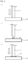
- the measurement method of the bond line thickness using a viscoelasticity measuring device is explained by reference to Fig. 5 .
- a cylindrical measuring tool having a diameter of 8 mm and a disc-shaped measuring tool are installed in a viscoelasticity measuring device.
- a cylindrical measuring tool 41 is pressed at a stress of 10 N against a disc-shaped measuring tool 42 as shown in Fig. 5(a) .
- a gap between the cylindrical measuring tool 41 and the disc-shaped measuring tool 42 is set to zero. Subsequently, as shown in Fig.
- the cylindrical measuring tool 41 is kept apart from the disc-shaped measuring tool 42 such that the gap between the cylindrical measuring tool 41 and the disc-shaped measuring tool 42 becomes 1 mm. Then, a heat-radiating grease 43 is arranged between the cylindrical measuring tool 41 and the disc-shaped measuring tool 42. As shown in Fig. 5(c) , the cylindrical measuring tool 41 is again pressed at a stress of 10 N against the disc-shaped measuring tool 42. Since the heat-radiating grease 43 is present between the cylindrical measuring tool 41 and the disc-shaped measuring tool 42, the gap between the cylindrical measuring tool 41 and the disc-shaped measuring tool 42 becomes larger than zero. The gap between the cylindrical measuring tool 41 and the disc-shaped measuring tool 42 at this time is expressed as the bond line thickness.
- the heat-radiating sheet in which the aforementioned area ratio (S2/S1) can be adjusted to 1.0 to 2.0 can be obtained by forming linear grooves intersecting each other on the surface of the heat-radiating sheet by means of embossing or the like.
- the aforementioned area ratio (S2/S1) it is especially efficient to form linear grooves on the whole heat-radiating sheet. It may be considered that by forming the plural grooves entirely on the heat-radiating sheet, even if expansion or contraction occurs in the heat-radiating sheet or the like, the heat-radiating grease can be retained in the grooves, whereby the aforementioned area ratio (S2/S1) can be made small.
- a distance between the adjacent grooves to each other is 100 to 1,500 ⁇ m
- a depth of the groove is 5 to 25 ⁇ m
- a width of the groove is 5 to 25 ⁇ m.
- the aforementioned area ratio (S2/S1) can be made small by shortening the distance between the adjacent grooves to each other, making the depth of the groove deep, or making the width of the groove large.
- the grooves may be formed on only one surface of the two main surfaces of the heat-radiating sheet, or the grooves may be formed on the both surfaces thereof.
- an area ratio (S2/S1) of an area (S2) of the heat-radiating grease after performing the heat cycle test of 100 cycles to an area (S1) of the heat-radiating grease expanded before performing the heat cycle test is 1.0 to 2.0, preferably 1.0 to 1.7, more preferably 1.0 to 1.5, and still more preferably 1.0 to 1.3.
- a surface roughness of the heat-radiating sheet of the present invention is preferably 1.2 to 3.5 ⁇ m, more preferably 1.5 to 3.2 pm, and still more preferably 2.0 to 3.0 pm in terms of an arithmetic average roughness (Ra).
- the surface roughness of the heat-radiating sheet of the present invention is preferably 10 to 25 ⁇ m, more preferably 14 to 23 pm, and still more preferably 17 to 23 pm in terms of a ten-point average roughness (Rz).
- the arithmetic average roughness (Ra) and the ten-point average roughness (Rz) are each a value measured in conformity with JIS B0601:2013.
- the area ratio (S2/S 1) can be adjusted by, for example, physically adjusting the surface through groove formation or the like, other method may also be adopted.
- the S2/S1 may be adjusted by chemically adjusting the surface state of the heat-radiating sheet. Specifically, there may be considered a method of modifying the surface with high compatibility with the heat-radiating grease.
- the components of the heat-radiating sheet of the present invention are not particularly limited so long as they are a component which is usually used for a heat-radiating sheet.
- the heat-radiating sheet of the present invention can contain a resin binder and a filler having a high thermal conductivity.
- the resin binder used for the heat-radiating sheet of the present invention is not particularly limited so long as it is a resin binder which is usually used for a heat-radiating sheet.
- the resin binder which is used for the heat-radiating sheet of the present invention include epoxy resins, silicone resins, acrylic resins, phenol resins, melamine resins, urea resins, unsaturated polyesters, fluorine resins, urethane resins, polyamides (for example, polyimide, polyamide-imide, and polyether imide), polyesters (for example, polybutylene terephthalate and polyethylene terephthalate), polyphenylene ethers, polyphenylene sulfides, wholly aromatic polyesters, polysulfones, liquid crystal polymers, polyether sulfones, polycarbonates, maleimide-modified resins, ABS resins, AAS (acrylonitrile-acrylic rubber/styrene) resins, and AES (acrylonitrile/ethylene/prop
- the resin binder is preferably a rubber or an elastomer.
- silicone resins are preferred from the viewpoint of heat resistance, weather resistance, electric insulation, and chemical stability.
- the silicone resin which is used for the heat-radiating sheet of the present invention is preferably an addition reaction type silicone resin.
- the addition reaction type silicone resin is one resulting from curing through a hydrosilylation reaction between an alkenyl group and a hydrogen atom bound to a silicon atom by using a platinum compound as a catalyst.
- Examples of the addition reaction type silicone resin include a trade name "LR3303-20A/B", manufactured by Wacker Asahikasei Silicone Co., Ltd.
- the filler used for the heat-radiating sheet of the present invention is not particularly limited so long as it is a filler which is usually used for a heat-radiating sheet.
- the filler used for the heat-radiating sheet of the present invention include an inorganic filler and a metal-based filler.
- the inorganic filler include zinc oxide, alumina, boron nitride, aluminum nitride, silicon carbide, and silicon nitride.
- Examples of the metal-based filler include aluminum, silver, and copper. These can be used either alone or in combination of two or more thereof. Of these, an inorganic filler is preferred from the viewpoint of electric insulation.
- boron nitride is more preferred from the viewpoint of thermal conductivity and chemical stability.
- a massive boron nitride particle in which the anisotropy of thermal conductivity is suppressed is still more preferred.
- the massive boron nitride particle is a particle resulting from massively coagulating flaky particles of hexagonal boron nitride.
- An average particle diameter of the filler is preferably 8 to 90 pm.
- the average particle diameter of the filler is 8 pm or more, the content of the filler can be made high.
- the average particle diameter of the filler is 90 pm or less, the heat-radiating sheet can be made thin.
- the average particle diameter of the filler is more preferably 20 to 70 pm, still more preferably 25 to 50 pm, and especially preferably 25 to 45 pm.
- the average particle diameter of the filler can be, for example, measured using a laser diffraction scattering particle size analyzer (LS-13 320), manufactured by Beckman-Coulter, Inc.
- LS-13 320 laser diffraction scattering particle size analyzer
- the obtained average particle diameter is, for example, an average particle diameter in terms of a volume statistics value.
- the content of the filler relative to 100% by volume of the total of the resin binder and the filler is preferably 30 to 85% by volume, and more preferably 40 to 80% by volume.
- the content of the filler is 30% by volume or more, the thermal conductivity of the heat-radiating sheet is improved, and a sufficient heat-radiating performance is readily obtained.
- the content of the filler is 85% by volume or less, the matter that the voids are liable to be formed at the time of molding the heat-radiating sheet can be suppressed, and the insulation and mechanical strength of the heat-radiating sheet can be enhanced.
- the heat-radiating sheet of the present invention may include a reinforcing layer.
- the reinforcing layer takes a role to further improve the mechanical strength of the heat-radiating sheet, and moreover, when the heat-radiating sheet is compressed in the thickness direction, there is also brought an effect for suppressing elongation of the heat-radiating sheet to the planar direction, thereby securing the insulation.
- the reinforcing layer examples include a glass cloth; an alumina cloth; a resin film made of polyester, polyamide, polyimide, polycarbonate, acrylic resin, etc.; a cloth fiber mesh cloth made of cotton, hemp, aramid fiber, cellulose fiber, nylon fiber, polyolefin fiber, etc.; a nonwoven fabric made of aramid fiber, cellulose fiber, nylon fiber, polyolefin fiber, etc.; a metal fiber mesh cloth made of stainless steel, copper, aluminum, etc.; and a metal foil made of copper, nickel, aluminum, etc. These can be used either alone or in combination of two or more thereof. Of these, a glass cloth is preferred from the viewpoint of thermal conductivity, insulation and costs.
- a thickness of the glass cloth is preferably 10 pm to 150 pm, more preferably 20 to 90 ⁇ m, and still more preferably 30 to 60 ⁇ m.
- the thickness of the glass cloth is 10 ⁇ m or more, the glass cloth can be suppressed from breakage at the time of handling.
- the thickness of the glass cloth is 150 pm or less, a lowering of the thermal conductivity of the heat-radiating sheet owing to the glass cloth can be suppressed.
- marketed glass cloths there are ones having a fiber diameter of 4 to 9 ⁇ m, and these can be used for the heat-radiating sheet 1.
- a tensile strength of the glass cloth is, for example, 100 to 1,000 N/25 mm.
- a length of one side of the opening of the glass cloth is preferably 0.1 to 1.0 mm from the viewpoint of balancing between the thermal conductivity and the strength.
- the glass cloth which can be used for the heat-radiating sheet 1 include a trade name "H25 F104", manufactured by Unitika Ltd.
- the heat-radiating sheet may be produced by applying a composition for heat-radiating sheet on both surfaces of the reinforcing layer such that the reinforcing layer is arranged in the center in the thickness direction of the heat-radiating sheet, or the heat-radiating sheet may be produced by applying a composition for heat-radiating sheet on one surface of the reinforcing layer.
- the heat-radiating sheet of the present invention may contain other component than the resin binder, the filler, and the reinforcing layer.
- the other component include an additive, a flame retarder, a silicone oil, a silane material, a silane coupling agent, a platinum catalyst, a curing agent, and a coloring agent.
- the content of the other component in 100% by volume of the volume of the heat-radiating sheet is, for example, 5% by volume or less, preferably 3% by volume or less, and more preferably 1% by volume or less.
- the heat-radiating sheet of the present invention may be provided with a base material resin layer.
- the base material resin layer takes a role to further improve the heat resistance of the heat-radiating sheet.
- the heat-radiating sheet of the present invention includes a resin composition layer containing the aforementioned resin binder and filler and a base material resin layer adjacent to this resin composition layer. Then, it is preferred that one surface of the resin composition layer is a surface in which the aforementioned area ratio (S2/S1) is 1.0 to 2.0, and the base material resin layer is arranged on the other surface of the resin composition layer.
- the resin composition layer may include the aforementioned reinforcing layer.
- the base material resin layer preferably contains a resin having a glass transition point of 200°C or higher. When the glass transition point is 200°C or higher, sufficient heat resistance is obtained, and the insulation or thermal conductivity of the laminate can be maintained favorable.
- the base material resin layer may be a layer formed of a coating film or may be formed of a film.
- the resin constituting the base material resin layer examples include a polyimide, a polyamide-imide, a polyamide (in particular, an aromatic polyamide), a polyether sulfone, a polyether imide, polyethylene naphthalate, polytetrafluoroethylene (PTFE), and a tetrafluoroethylene/perfluoroalkyl vinyl ether copolymer (PFA).
- a polyimide is preferred.
- these resins can be used either alone or in combination of several kinds thereof.
- the content of the resin in the base material resin layer is not particularly limited, a lower limit thereof is preferably 78% by volume or more, more preferably 80% by volume or more, and still more preferably 82% by volume or more.
- An upper limit thereof is preferably 92% by volume or less, more preferably 90% by volume or less, and still more preferably 88% by volume or less.
- the base material resin layer contains an inorganic filler.
- the insulation, thermal conductivity, peel strength, and so on can be improved.
- the rise of the peel strength resides in the matter that unevennesses are formed at an interface between the base material resin layer and the resin composition layer owing to the inorganic filler, whereby an anchor effect is produced.
- the inorganic filler the same materials as those in the aforementioned filler can be used.
- the content of the inorganic filler in the base material resin layer is not particularly limited, a lower limit thereof is preferably 8% by volume or more, more preferably 10% by volume or more, and still more preferably 12% by volume or more.
- An upper limit thereof is preferably 22% by volume or less, more preferably 20% by volume or less, and still more preferably 18% by volume or less.
- the aforementioned other component may be contained in a small amount, and impurities may be contained in small amounts.
- the total content of the aforementioned resin and inorganic filler is preferably 90% by volume or more, more preferably 95% by volume or more, and still more preferably 97% by volume or more.
- the thickness of the base material resin layer is preferably the following range.
- a lower limit thereof is preferably 0.010 mm or more.
- the thickness of the base material resin layer is more preferably 0.012 mm or more, and still more preferably 0.015 mm or more.
- An upper limit thereof is preferably 0.100 mm or less, more preferably 0.070 mm or less, and still more preferably 0.050 mm or less.
- the film serving as the base material resin layer can be fabricated in conformity with a known film fabricating method.
- products which are on sale in the market may be acquired and used.
- the resin composition (composition for heat-radiating sheet) is applied on a base material sheet serving as the base material resin layer.
- a conventionally known method for example, a coater method, a doctor blade method, an extrusion molding method, an injection molding method, and a press molding method, can be adopted.
- the composition for heat-radiating sheet may be applied on both surfaces of the base material resin layer such that the base material resin layer is arranged in the center in the thickness direction of the heat-radiating sheet, or the composition for heat-radiating sheet may be applied on only one surface thereof,
- the form of the heat-radiating sheet of the present invention is not particularly limited.
- the heat-radiating sheet of the present invention may be any of a sheet product and a roll product.
- a heat-radiating sheet laminate 10 of an embodiment of the present invention includes a heat-radiating sheet 1 of an embodiment of the present invention and a heat-radiating grease layer 11 formed on a surface of the heat-radiating sheet 1. According to this, not only the contact thermal resistance between a heat-generating element 21 and the heat-radiating sheet 1 can be reduced, but also the pump-out phenomenon of the heat-radiating grease can be suppressed.
- the surface of the heat-radiating sheet 1 on which the heat-radiating grease layer 11 is formed has a surface state in which the area ratio (S2/S1) falls within the aforementioned range.
- the heat-radiating grease 11 which is used for the heat-radiating sheet laminate 10 of an embodiment of the present invention is not particularly limited so long as it is a heat-radiating grease which is usually used as a heat-radiating material.
- the heat-radiating grease is one prepared by kneading a liquid polymer and a filler in a paste-like form.
- the filler for example, the same materials as those in the aforementioned filler used for the heat-radiating sheet of the present invention can be used. Of these, from the viewpoint of electric insulation, inorganic fillers are preferred, and among the inorganic fillers, alumina is more preferred from the viewpoint of thermal conductivity and insulation as well as costs.
- the shape of the alumina may be any of a spherical shape, a granular shape, a platy shape, and an amorphous shape, it is especially preferably a spherical shape from the viewpoint of fluidity.
- liquid polymer examples include hydrocarbon oils, such as a polyolefin, an alkyl aromatic compound, and an alicyclic compound; polyethers, such as a polyglycol and a phenyl ether; esters, such as a diester and a polyol ester; phosphorus compounds, such as an aromatic phosphoric acid ester; silicon compounds, such as a silicone; halogen compounds, such as a fluorinated polyether; mineral oils; fluorosilicones; acrylic reins; and urethane resins.
- silicones are preferred from the viewpoint of heat resistance, weather resistance, electric insulation, and chemical stability.
- the kind of the heat-radiating grease is not particularly limited, a value of the viscosity at 25°C of a usual heat-radiating grease is 10 to 400 Pa ⁇ s, and in the case of using a usual heat-radiating grease having such a viscosity, the pump-out phenomenon can be more effectively suppressed.
- the heat-radiating sheet of the present invention is effective for a heat-radiating grease having a low viscosity. What the viscosity is lower is preferred from the viewpoint of easiness of handling of the heat-radiating grease, etc., but there is involved such a problem that the pump-out phenomenon is liable to occur.
- the heat-radiating grease having a low viscosity as referred to herein means a heat-radiating grease having a value of viscosity at 25°C of 300 Pa ⁇ s or less.
- a value of the bond line thickness of a usual heat-radiating grease is 10 to 120 ⁇ m, and in the case of using a usual heat-radiating grease having such a bond line thickness, the pump-out phenomenon can be more effectively suppressed.
- the heat-radiating sheet of the present invention is effective for a heat-radiating grease having a small bond line thickness. What the bond line thickness is smaller is preferred from the viewpoint of thermal resistance, etc., but there is involved such a problem that the pump-out phenomenon is liable to occur.
- the heat-radiating grease having a small bond line thickness as referred to herein means a heat-radiating grease having a value of bond line thickness of 60 pm or less.
- the use amount of the heat-radiating grease 11 which is used for the heat-radiating sheet laminate 10 of an embodiment of the present invention may be 1.5 to 8.0 mL, may be 2.3 to 4.5 mL, or may be 2.6 to 3.8 mL per 180 mm ⁇ 100 mm of the heat-radiating sheet so long as the shape of the groove, or the like falls within the aforementioned preferred range.
- the viscosity may be adjusted by, for example, a method of vacuum defoaming/mixing.
- the heat-radiating sheet laminate of an embodiment of the present invention can be modified as follows.
- the heat-radiating grease 11 is arranged on only one surface side of the heat-radiating sheet 1. But, as in a heat-radiating sheet laminate 10A shown in Fig. 2 , the heat-radiating grease 11 and 12 may be arranged on the both sides of the heat-radiating sheet 1. According to this, the contact thermal resistance between the heat-radiating sheet 1 and a heat sink 30 can also be reduced. In this case, the both surfaces of the heat-radiating sheet 1 have a surface state such that the aforementioned area ratio (S2/S1) of the heat-radiating grease falls within the aforementioned range.
- a structure 20 of an embodiment of the present invention includes the heat-radiating sheet 1 of an embodiment of the present invention, the heat-generating element 21 placed on the heat-radiating sheet 1, and the heat-radiating grease 11 intervening between the heat-generating sheet 1 and the heat-generating element 21.
- the surface of the heat-radiating sheet 1 having the heat-radiating grease 11 arranged therein has a surface state such that the aforementioned area ratio (S2/S1) of the heat-radiating grease falls within the aforementioned range.
- the same materials as those in the aforementioned heat-radiating grease used for the aforementioned heat-radiating sheet laminate can be used.
- heat-generating element examples include power devices, transistors, thyristors, CPUs, IGBT modules, and diodes.
- the heat-radiating grease 11 is arranged on only one surface side of the heat-radiating sheet 1. But, as in a structure 20A shown in Fig. 2 , the heat-radiating grease 11 and 12 may be arranged on the both sides of the heat-radiating sheet 1. According to this, the contact thermal resistance between the heat-radiating sheet 1 and the heat sink 30 can be reduced, too. In this case, the both surfaces of the heat-radiating sheet 1 have a surface state such that the aforementioned area ratio (S2/S 1) of the heat-radiating grease falls within the aforementioned range.
- a substrate having a heat-generating element mounted therein may be placed on the heat-radiating sheet.
- a heat-radiating treatment method of a heat-generating element of the present invention includes a step of applying the heat-radiating sheet of the present invention, which has a first surface and a second surface on the opposite side to the first surface, with a heat-radiating grease on at least one surface of the first surface and the second surface; and a step of arranging a heat-generating element on the surface of the heat-radiating sheet, on which the heat-radiating grease has been applied. According to this, not only the contact thermal resistance between the heat-generating element and the heat-radiating sheet can be reduced, but also the pump-out phenomenon of the heat-radiating grease can be suppressed.
- an auto dispense or screen printing method is adopted for the application with the heat-radiating grease.
- heat-radiating sheet laminate 10 and structure 20 of an embodiment of the present invention and modified examples 10A and 20A thereof are each merely one mode and do not limit the heat-radiating sheet laminate and structure of the present invention.
- the thickness of the heat-radiating sheet was measured with a thickness gauge (Model No.: 547-301, manufactured by Mitutoyo Corporation) with respect to ten optional places, and an average value thereof was expressed as the thickness of the heat-radiating sheet.
- the surface roughness of the heat-radiating sheet was measured with a confocal microscope (trade name: LT ⁇ 9010M, manufactured by Keyence Corporation) under conditions of a measured length of 10,000 pm, a measured pitch of 10 pm, and a measured velocity of 500 pm in conformity with JIS B0601:2013.
- a heat cycle test was performed using an area ratio evaluating tool 100 shown in Fig. 3 , to examine the aforementioned area ratio (S2/S1) of the heat-radiating grease.
- the area ratio evaluating tool 100 is described by reference to Fig. 3 .
- the area ratio evaluating tool 100 includes an aluminum plate 110 on which a heat-radiating sheet 200 is placed; a transparent glass plate 120 sandwiching the heat-radiating sheet 200 and a heat-radiating grease 300 to be dropped on the heat-radiating sheet in combination with the aluminum plate 110; a transparent resin-made glass plate fixing plate 130 fixing the glass plate 120; and bolts 140 and nuts 150 used for fastening a gap between the aluminum plate 110 and the glass plate 120.
- the aluminum plate 110 is provided with holes 111 for passing screw parts 141 of the bolts 140 therethrough.
- the glass plate fixing plate 130 is provided with hollow parts 131 for fitting the glass plate 120 and holes 132 for passing the screw parts 141 of the bolts 140 therethrough. The depth of the hollow part 131 is slightly smaller than the thickness of the glass plate 120.
- the aluminum plate 110 an aluminum plate having a quality of material of A-5052 was used.
- the size of the aluminum plate 110 was 180 mm ⁇ 100 mm ⁇ 10 mm.
- the size of the glass plate 120 was 70 mm ⁇ 55 mm ⁇ 10 mm.
- a vinyl chloride-based resin was used for the glass plate fixing plate 130.
- the size of the glass plate fixing plate 130 was 180 mm ⁇ 100 mm ⁇ 30 mmmm.
- the heat-radiating sheet 200 provided with holes 210 for passing the screw parts 141 of the bolt 140 therethrough and having a size of 180 mm ⁇ 100 m was placed on the aluminum plate 110. Then, 3.2 mL of the heat-radiating grease 300 was dropped on the heat-radiating sheet 110 placed on the aluminum plate 110. A position of the heat-radiating sheet 200 at which the heat-radiating grease 300 was dropped was a position corresponding to the center of the glass plate 120 to be placed on the heat-radiating grease 300.
- the glass plate fixing plate 130 having the glass plate 120 fitted therein was placed on the heat-radiating sheet 200 on which the heat-radiating grease 300 had been dropped. According to this, the heat-radiating grease 300 was sandwiched by the heat-radiating sheet 200 and the glass plate 120. Then, the screw parts 141 of the bolts 140 were inserted into the holes 111 of the aluminum plate 110, the holes 210 of the heat-radiating sheet 200, and the holes 131 of the glass plate fixing plate 130, respectively, and then, the gap between the aluminum plate 110 and the glass plate 120 was fasten using the nuts 150. A fastening force per unit area of the gap between the aluminum plate 110 and the glass plate 120 was 0.2 MPa. As shown in Fig.
- the spread state of the heat-radiating grease 300 could be seen through the glass plate 120 and the glass plate fixing plate 130. Then, the heat-radiating grease 300 was photographed through the glass plate 120 and the glass plate fixing plate 130, and an area (S1) of the spread heat-radiating grease 300 was measured from the photographed image. In Fig. 4 , an area of the heat-radiating grease 300 sandwiched between the glass plate 120 and the heat-radiating sheet is corresponding to the area (S1) of the heat-radiating grease in the heat-radiating sheet of the present invention.
- the area ratio evaluating tool 100 having the heat-radiating sheet 200 and the heat-radiating grease 300 sandwiched therein was made horizontal to perform the heat cycle test.
- the heat cycle test in which the operation of holding at a temperature of -40°C for 30 minutes and then holding at a temperature of 125°C for 30 minutes was one cycle was performed 100 cycles.
- the heat-radiating grease 300 was photographed through the glass plate 120 and the glass plate-fixing plate 130, an area (S2) of the spread heat-radiating grease 300 was measured from the photographed image.
- S2 area of the spread heat-radiating grease 300
- an area of the heat-radiating grease 300 sandwiched between the glass plate 120 and the heat-radiating sheet after the heat cycle test of 100 cycles is corresponding to the area (S2) of the heat-radiating grease in the heat-radiating sheet of the present invention. Then, the area ratio (S2/S1) of the area (S2) of the heat-radiating grease after the heat cycle test of 100 cycles to the area (S1) of the heat-radiating grease before the heat cycle test was calculated. For the area ratio evaluating test, the following heat-radiating grease was used.
- Heat-radiating grease Trade name: GFC-PF3, manufactured by Denka Company Limited, viscosity at 25°C at a shear velocity of 10 s -1 : 22 Pa ⁇ s, bond line thickness: 52 pm, dropped amount: 3.2 mL
- a power module assembly (PM-Assy) (Model No.: TO-3P Shape Transistor, manufactured by Toshiba Corporation) was arranged in place of the glass plate 120 and the glass plate fixing plate 130, and the heat cycle test was performed.
- PM-Assy Power module assembly
- TO-3P Shape Transistor manufactured by Toshiba Corporation
- the heat cycle test 0.16 mL of the heat-radiating grease was dropped on the heat-radiating sheet placed on an aluminum plate (Model No.: 40CH104, manufactured by Ryosan Company, Limited).
- a position of the heat-radiating sheet at which the heat-radiating grease was dropped was a position corresponding to the center of the PM-Assy to be placed on the heat-radiating grease.
- the PM-Assy was placed on the heat-radiating sheet on which the heat-radiating greased had been dropped. According to this, the heat-radiating grease was sandwiched by the heat-radiating sheet and the PM-Assy. Then, the screw parts of the bolts were inserted into the holes of the aluminum plate, the holes of the heat-radiating sheet, and the holes of the PM-Assy, respectively, and then, the gap between the aluminum plate and the PM-Assy was fasten using the nuts. A fastening force per unit area of the gap between the aluminum plate and the PM-Assy was 1.0 MPa.
- the PM-Assy was made horizontal to perform the heat cycle test.
- the heat cycle test in which the operation of holding at a temperature of -40°C for 30 minutes and the holding at a temperature of 125°C for 30 minutes was one cycle was performed 100 cycles. Then, after the heat cycle test of 100 cycles, the presence or absence of flowing out of the heat-radiating grease from the gap between the PM-Assy and the heat-radiating sheet was confirmed.
- the heat-radiating sheets of the Examples and Comparative Example were fabricated in the following manner.
- Boric acid, melamine, and calcium carbonate (all being a special grade reagent) were mixed in a proportion of 70/50/5 in terms of a mass ratio; the temperature was raised in a nitrogen gas atmosphere from room temperature to 1,400°C over 1 hour; after retaining at 1,400°C for 3 hours, the temperature was raised to 1,900°C over 4 hours; and after retaining at 1,900°C for 2 hours, cooling to room temperature was performed to produce hexagonal boron nitride. After crushing this, the resultant was pulverized and sieved to fabricate a massive boron nitride particle. An average particle diameter of the fabricated massive boron nitride particle was 50 ⁇ m.
- the aforementioned composition for heat-radiating sheet was applied in a thickness of 0.5 mm per surface by using a comma coater and dried at 75°C for 5 minutes. Thereafter, using a flat plate pressing machine (manufactured by Yanase Seisakusho Co., Ltd.), pressing was performed for 10 minutes under conditions at a temperature of 120°C and a pressure of 50 kgf/cm 2 , to fabricate a sheet having a thickness of 0.30 mm. Subsequently, secondary heating was performed at atmospheric pressure at a temperature of 150°C for 4 hours, to fabricate a heat-radiating sheet precursor sheet.
- a flat plate pressing machine manufactured by Yanase Seisakusho Co., Ltd.
- a transfer sheet on the surface of which plural first projections extending in a first direction and plural second projections extending in a second direction different from the first direction and intersecting the first grooves were provided, was prepared.
- a distance between the adjacent first projections to each other and a distance between the adjacent second projections to each other were each 1.0 mm.
- a width of each of the first projections and the second projections was 10 pm.
- a height of each of the first projections and the second projections was 20 pm.
- an angle formed by the first direction and the second direction was 90°.
- the first projections and the second projections were each a linearly extending projection.
- a shape of the cross-section of each of the first projections and the second projections was quadrilateral.
- the aforementioned transfer sheet was placed on the heat-radiating sheet precursor sheet, and then, using a flat plate pressing machine (manufactured by Yanase Seisakusho Co., Ltd.), pressing was performed for 30 minutes under conditions at a temperature of 165°C and a pressure of 150 kgf/cm 2 , to form grooves on the surface of the heat-radiating sheet precursor sheet. There was thus fabricated a heat-radiating sheet of Example 1.
- a heat-radiating sheet of Example 2 was fabricated in the same manner as in Example 1, except that the pressure of the flat pressing machine at the time of forming grooves on the surface of the heat-radiating sheet precursor sheet was changed from 150 kgf/cm 2 to 220 kgf/cm 2 .
- a heat-radiating sheet of Example 3 was fabricated in the same manner as in Example 1, except that the pressure of the flat pressing machine at the time of forming grooves on the surface of the heat-radiating sheet precursor sheet was changed from 150 kgf/cm 2 to 50 kgf/cm 2 .
- a polyimide film (trade name: Kapton 100H, manufactured by "DU PONT-TORAY CO., LTD., thickness: 0.026 mm) was arranged as a base material resin layer on a Teflon (registered trademark) sheet, and then, the aforementioned composition for heat-radiating sheet was applied in a thickness of 0.2 mm on the polyimide film by using a comma coater and dried at 75°C for 5 minutes, to apply the composition for heat-radiating sheet on one surface of the polyimide film.
- a polyimide film trade name: Kapton 100H, manufactured by "DU PONT-TORAY CO., LTD., thickness: 0.026 mm
- Teflon registered trademark
- the resultant was turned over such that the polyimide film was located on the upper side; the composition for heat-radiating sheet was applied in a thickness of 0.2 mm on the polyimide film by using a comma coater and then dried at 75°C for 5 minutes, to fabricate a sheet of the composition for heat-radiating sheet having the composition for heat-radiating sheet on the both surfaces thereof.
- the same method as in Example 1 was performed to fabricate a heat-radiating sheet of Example 4.
- a heat-radiating sheet of Comparative Example 1 was fabricated in the same manner as in Example 1, except that no groove was formed on the surface of the heat-radiating sheet precursor sheet.
- the dielectric breakdown voltage of Examples 1 and 4 was evaluated by a short-time breakdown test (at room temperature: 23°C) in conformity with JIS C2110. As a result, in Examples 4, the dielectric breakdown voltage was higher by about 3 kV.
Abstract
Description
- The present invention relates to a heat-radiating sheet, a heat-radiating sheet laminate including the heat-radiating sheet, a structure including the heat-radiating sheet, and a heat-radiating treatment method of a heat-generating element using the heat-radiating sheet.
- In heat-generating elements, such as power devices, transistors, thyristors, and CPUs, how to efficiently radiate heat generated at the time of use is an important issue. As a countermeasure against such heat radiation, in general, the heat radiation has hitherto been performed by conducting the heat generated from the heat-generating element into a heat-radiating component, such as a heat sink. In order to thermally conduct the heat generated from the heat-generating element with efficiency into the heat-radiating component, it is desired to fill an air gap with a heat-radiating material at a contact interface between the heat-generating element and the heat-radiating component. Heat-radiating sheets have hitherto been used as such a heat-radiating material because of easy handling (see, for example, PTL 1).
- PTL:
JP 2012-39060 A - However, since the heat-radiating sheet cannot follow micro unevennesses on the mounting surface of the heat-generating element, there is a case where adhesion of the heat-radiating sheet to the heat-generating element is insufficient. Accordingly, there was a case where contact thermal resistance between the heat-generating element and the heat-generating sheet becomes large.
- As a result of extensive and intensive investigations made by the present inventors, it has been found that by allowing a heat-radiating grease to intervene between the heat-generating element and the heat-radiating sheet, the contact thermal resistance between the heat-generating element and the heat-radiating sheet can be reduced. But, the present inventors have also found that when the heat-radiating grease is allowed to intervene between the heat-generating element and the heat-radiating sheet, a remarkable pump-out phenomenon (phenomenon in which the heat-radiating grease flows out from a mounting section) occurs in the heat-radiating grease due to thermal expansion and thermal contraction of the heat-radiating sheet.
- Then, an object of the present invention is to provide a heat-radiating sheet which when allowing a heat-radiating grease to intervene between a heat-generating element and a heat-radiating sheet, is able to suppress a pump-out phenomenon of the heat-radiating grease, a heat-radiating sheet laminate including the heat-radiating sheet, a structure including the heat-radiating sheet, and a heat-radiating treatment method of a heat-generating element using the heat-radiating sheet.
- In order to achieve the aforementioned object, the present inventors made extensive and intensive investigations. As a result, it has been found that in the case of performing a predetermined heat cycle test by sandwiching a heat-radiating grease by a heat-radiating sheet placed on an aluminum plate and a glass plate, the aforementioned object can be achieved by using a heat-radiating sheet in which an area ratio of an area of the heat-radiating grease after the heat cycle test to an area of the heat-radiating grease before the heat cycle test falls within a predetermined range.
- The present invention is based on the aforementioned findings, and a gist thereof is as follows.
- [1] A heat-radiating sheet, wherein when a heat cycle test of one cycle in which 3.2 mL of a heat-radiating grease having a viscosity at 25°C at a shear velocity of 10 s-1 of 22 Pa·s and a bond line thickness (BLT) of 52 pm is sandwiched between a heat-radiating sheet of 180 mm × 100 mm arranged on an aluminum plate and a glass plate by a clamping force of 0.2 MPa per unit area, and after expanding the heat-radiating grease, the heat-radiating sheet is held at a temperature of -40°C for 30 minutes and then held at a temperature of 125°C for 30 minutes, is performed 100 cycles, an area ratio (S2/S1) of an area (S2) of the heat-radiating grease after performing the heat cycle test of 100 cycles to an area (S1) of the heat-radiating grease expanded before performing the heat cycle test is 1.0 to 2.0.
- [2] The heat-radiating sheet as set forth above in [1], wherein the area ratio (S2/S1) is 1.0 to 1.7.
- [3] A heat-radiating sheet laminate including the heat-radiating sheet as set forth above in [1] or [2], which has a first surface and a second surface on the opposite side to the first surface; and a heat-radiating grease layer formed on at least one surface of the first surface and the second surface of the heat-radiating sheet.
- [4] A structure including the heat-radiating sheet as set forth above in [1] or [2], a heat-generating element placed on the heat-radiating sheet, and a heat-radiating grease intervening between the heat-radiating sheet and the heat-generating element.
- [5] A heat-radiating treatment method including a step of applying the heat-radiating sheet according to claim 1 or 2, which has a first surface and a second surface on the opposite side to the first surface, with a heat-radiating grease on at least one surface of the first surface and the second surface; and a step of arranging a heat-generating element on the surface of the heat-radiating sheet, on which the heat-radiating grease has been applied.
- In accordance with the present invention, it is possible to provide a heat-radiating sheet which when allowing a heat-radiating grease to intervene between a heat-generating element and a heat-radiating sheet, is able to suppress a pump-out phenomenon of the heat-radiating grease, a heat-radiating sheet laminate including the heat-radiating sheet, a structure including the heat-radiating sheet, and a heat-radiating treatment method of a heat-generating element using the heat-radiating sheet.
-
- "
Fig. 1 " is a view for explaining heat-radiating sheet laminate and structure of an embodiment of the present invention. - "
Fig. 2 " is a view for explaining a modification example of heat-radiating sheet laminate and structure of an embodiment of the present invention. - "
Fig. 3 " is an exploded view of an area ratio evaluating tool used for the heat cycle test in the Examples. - "
Fig. 4 " is a view for explaining an expanse of a heat-radiating grease in an area ratio evaluating tool. - "
Fig. 5 " is a view for explaining a measurement method of a bond line thickness using a viscoelasticity measuring device. - The heat-radiating sheet of the present invention is such that when a heat cycle test of one cycle in which 3.2 mL of a heat-radiating grease having a viscosity at 25°C at a shear velocity of 10 s-1 of 22 Pa·s and a bond line thickness of 52 µm is sandwiched between a heat-radiating sheet of 180 mm × 100 mm arranged on an aluminum plate and a glass plate by a clamping force of 0.2 MPa per unit area, and after expanding the heat-radiating grease, the heat-radiating sheet is held at a temperature of -40°C for 30 minutes and then held at a temperature of 125°C for 30 minutes, is performed 100 cycles, an area ratio (S2/S1) of an area (S2) of the heat-radiating grease after performing the heat cycle test of 100 cycles to an area (S1) of the heat-radiating grease expanded before performing the heat cycle test is 1.0 to 2.0. Specifically, in the heat-radiating sheet of the present invention, in the heat cycle test using a glass plate as mentioned in the section of Examples as mentioned later, the area ratio (S2/S1) of the area (S2) of the heat-radiating grease after performing the heat cycle test of 100 cycles to the area (S1) of the heat-radiating grease expanded before performing the heat cycle test is 1.0 to 2.0. When the aforementioned area ratio (S2/S1) is larger than 2.0, at the time of allowing the heat-radiating grease layer to intervene between the heat-generating element and the heat-radiating sheet, there is a case where the pump-out phenomenon of the heat-radiating grease becomes remarkable. The viscosity value "22 Pa·s" at 25°C of the heat-radiating grease is typically one of values of viscosity at 25°C of the heat-radiating grease to be used. In addition, the bond line thickness value "52 pm" of the heat-radiating grease is typically one of values of bond line thicknesses of the heat-radiating grease to be used. By adjusting the aforementioned area ratio measured using the heat-radiating grease having such viscosity and bond line thickness so as to fall within the specified range, in the case of using a typical heat-radiating grease, the pump-out phenomenon can be effectively suppressed.
- The bond line thickness can be measured using a viscoelasticity measuring device. The measurement method of the bond line thickness using a viscoelasticity measuring device is explained by reference to
Fig. 5 . A cylindrical measuring tool having a diameter of 8 mm and a disc-shaped measuring tool are installed in a viscoelasticity measuring device. Then, utilizing a function of the viscoelasticity measuring device to deform a sample in the compression direction, acylindrical measuring tool 41 is pressed at a stress of 10 N against a disc-shaped measuring tool 42 as shown inFig. 5(a) . At this time, a gap between thecylindrical measuring tool 41 and the disc-shaped measuring tool 42 is set to zero. Subsequently, as shown inFig. 5(b) , thecylindrical measuring tool 41 is kept apart from the disc-shaped measuring tool 42 such that the gap between thecylindrical measuring tool 41 and the disc-shaped measuring tool 42 becomes 1 mm. Then, a heat-radiatinggrease 43 is arranged between thecylindrical measuring tool 41 and the disc-shaped measuring tool 42. As shown inFig. 5(c) , thecylindrical measuring tool 41 is again pressed at a stress of 10 N against the disc-shaped measuring tool 42. Since the heat-radiating grease 43 is present between thecylindrical measuring tool 41 and the disc-shaped measuring tool 42, the gap between thecylindrical measuring tool 41 and the disc-shaped measuring tool 42 becomes larger than zero. The gap between thecylindrical measuring tool 41 and the disc-shaped measuring tool 42 at this time is expressed as the bond line thickness. - For example, the heat-radiating sheet in which the aforementioned area ratio (S2/S1) can be adjusted to 1.0 to 2.0 can be obtained by forming linear grooves intersecting each other on the surface of the heat-radiating sheet by means of embossing or the like. In adjusting the aforementioned area ratio (S2/S1), it is especially efficient to form linear grooves on the whole heat-radiating sheet. It may be considered that by forming the plural grooves entirely on the heat-radiating sheet, even if expansion or contraction occurs in the heat-radiating sheet or the like, the heat-radiating grease can be retained in the grooves, whereby the aforementioned area ratio (S2/S1) can be made small. In addition, it is preferred that a distance between the adjacent grooves to each other is 100 to 1,500 µm, a depth of the groove is 5 to 25 µm, and a width of the groove is 5 to 25 µm. In addition, the aforementioned area ratio (S2/S1) can be made small by shortening the distance between the adjacent grooves to each other, making the depth of the groove deep, or making the width of the groove large. The grooves may be formed on only one surface of the two main surfaces of the heat-radiating sheet, or the grooves may be formed on the both surfaces thereof.
- When the heat-radiating grease is allowed to intervene between the heat-generating element and the heat-radiating sheet, from the viewpoint that the pump-out phenomenon of the heat-radiating grease can be suppressed more largely, an area ratio (S2/S1) of an area (S2) of the heat-radiating grease after performing the heat cycle test of 100 cycles to an area (S1) of the heat-radiating grease expanded before performing the heat cycle test is 1.0 to 2.0, preferably 1.0 to 1.7, more preferably 1.0 to 1.5, and still more preferably 1.0 to 1.3.
- When the heat-radiating grease is allowed to intervene between the heat-generating element and the heat-radiating sheet, from the viewpoint that the pump-out phenomenon of the heat-radiating grease can be suppressed more largely, a surface roughness of the heat-radiating sheet of the present invention is preferably 1.2 to 3.5 µm, more preferably 1.5 to 3.2 pm, and still more preferably 2.0 to 3.0 pm in terms of an arithmetic average roughness (Ra). In addition, the surface roughness of the heat-radiating sheet of the present invention is preferably 10 to 25 µm, more preferably 14 to 23 pm, and still more preferably 17 to 23 pm in terms of a ten-point average roughness (Rz). The arithmetic average roughness (Ra) and the ten-point average roughness (Rz) are each a value measured in conformity with JIS B0601:2013.
- As mentioned above, though the area ratio (S2/S 1) can be adjusted by, for example, physically adjusting the surface through groove formation or the like, other method may also be adopted. For example, the S2/S1 may be adjusted by chemically adjusting the surface state of the heat-radiating sheet. Specifically, there may be considered a method of modifying the surface with high compatibility with the heat-radiating grease.
- The components of the heat-radiating sheet of the present invention are not particularly limited so long as they are a component which is usually used for a heat-radiating sheet. For example, the heat-radiating sheet of the present invention can contain a resin binder and a filler having a high thermal conductivity.
- The resin binder used for the heat-radiating sheet of the present invention is not particularly limited so long as it is a resin binder which is usually used for a heat-radiating sheet. Examples of the resin binder which is used for the heat-radiating sheet of the present invention include epoxy resins, silicone resins, acrylic resins, phenol resins, melamine resins, urea resins, unsaturated polyesters, fluorine resins, urethane resins, polyamides (for example, polyimide, polyamide-imide, and polyether imide), polyesters (for example, polybutylene terephthalate and polyethylene terephthalate), polyphenylene ethers, polyphenylene sulfides, wholly aromatic polyesters, polysulfones, liquid crystal polymers, polyether sulfones, polycarbonates, maleimide-modified resins, ABS resins, AAS (acrylonitrile-acrylic rubber/styrene) resins, and AES (acrylonitrile/ethylene/propylene/diene rubber-styrene) resins. These can be used either alone or in combination of two or more thereof. From the viewpoint of facilitating handling of the heat-radiating sheet and the viewpoint of more enhancing adhesion of the heat-radiating sheet, the resin binder is preferably a rubber or an elastomer. Of these, silicone resins are preferred from the viewpoint of heat resistance, weather resistance, electric insulation, and chemical stability.
- From the viewpoint that ionic impurities as a cause of metal corrosion are not contained and that by-products are not formed after the reaction, the silicone resin which is used for the heat-radiating sheet of the present invention is preferably an addition reaction type silicone resin. The addition reaction type silicone resin is one resulting from curing through a hydrosilylation reaction between an alkenyl group and a hydrogen atom bound to a silicon atom by using a platinum compound as a catalyst. Examples of the addition reaction type silicone resin include a trade name "LR3303-20A/B", manufactured by Wacker Asahikasei Silicone Co., Ltd.
- The filler used for the heat-radiating sheet of the present invention is not particularly limited so long as it is a filler which is usually used for a heat-radiating sheet. Examples of the filler used for the heat-radiating sheet of the present invention include an inorganic filler and a metal-based filler. Examples of the inorganic filler include zinc oxide, alumina, boron nitride, aluminum nitride, silicon carbide, and silicon nitride. Examples of the metal-based filler include aluminum, silver, and copper. These can be used either alone or in combination of two or more thereof. Of these, an inorganic filler is preferred from the viewpoint of electric insulation. Among the inorganic fillers, boron nitride is more preferred from the viewpoint of thermal conductivity and chemical stability. In addition, since the boron nitride has anisotropy in the thermal conductivity, a massive boron nitride particle in which the anisotropy of thermal conductivity is suppressed is still more preferred. The massive boron nitride particle is a particle resulting from massively coagulating flaky particles of hexagonal boron nitride.
- An average particle diameter of the filler is preferably 8 to 90 pm. When the average particle diameter of the filler is 8 pm or more, the content of the filler can be made high. On the other hand, when the average particle diameter of the filler is 90 pm or less, the heat-radiating sheet can be made thin. From such viewpoint, the average particle diameter of the filler is more preferably 20 to 70 pm, still more preferably 25 to 50 pm, and especially preferably 25 to 45 pm. The average particle diameter of the filler can be, for example, measured using a laser diffraction scattering particle size analyzer (LS-13 320), manufactured by Beckman-Coulter, Inc. As the average particle diameter of the filler, one measured without applying a homogenizer thereto before the measurement treatment can be adopted. The obtained average particle diameter is, for example, an average particle diameter in terms of a volume statistics value.
- The content of the filler relative to 100% by volume of the total of the resin binder and the filler is preferably 30 to 85% by volume, and more preferably 40 to 80% by volume. In the case where the content of the filler is 30% by volume or more, the thermal conductivity of the heat-radiating sheet is improved, and a sufficient heat-radiating performance is readily obtained. In addition, in the case where the content of the filler is 85% by volume or less, the matter that the voids are liable to be formed at the time of molding the heat-radiating sheet can be suppressed, and the insulation and mechanical strength of the heat-radiating sheet can be enhanced.
- The heat-radiating sheet of the present invention may include a reinforcing layer. The reinforcing layer takes a role to further improve the mechanical strength of the heat-radiating sheet, and moreover, when the heat-radiating sheet is compressed in the thickness direction, there is also brought an effect for suppressing elongation of the heat-radiating sheet to the planar direction, thereby securing the insulation. Examples of the reinforcing layer include a glass cloth; an alumina cloth; a resin film made of polyester, polyamide, polyimide, polycarbonate, acrylic resin, etc.; a cloth fiber mesh cloth made of cotton, hemp, aramid fiber, cellulose fiber, nylon fiber, polyolefin fiber, etc.; a nonwoven fabric made of aramid fiber, cellulose fiber, nylon fiber, polyolefin fiber, etc.; a metal fiber mesh cloth made of stainless steel, copper, aluminum, etc.; and a metal foil made of copper, nickel, aluminum, etc. These can be used either alone or in combination of two or more thereof. Of these, a glass cloth is preferred from the viewpoint of thermal conductivity, insulation and costs.
- In the case of using a glass cloth as the reinforcing layer, a generally marketed glass cloth having openings can be used. From the viewpoint of thermal conductivity, a thickness of the glass cloth is preferably 10 pm to 150 pm, more preferably 20 to 90 µm, and still more preferably 30 to 60 µm. In the case where the thickness of the glass cloth is 10 µm or more, the glass cloth can be suppressed from breakage at the time of handling. On the other hand, in the case where the thickness of the glass cloth is 150 pm or less, a lowering of the thermal conductivity of the heat-radiating sheet owing to the glass cloth can be suppressed. Among marketed glass cloths, there are ones having a fiber diameter of 4 to 9 µm, and these can be used for the heat-radiating
sheet 1. In addition, a tensile strength of the glass cloth is, for example, 100 to 1,000 N/25 mm. In addition, a length of one side of the opening of the glass cloth is preferably 0.1 to 1.0 mm from the viewpoint of balancing between the thermal conductivity and the strength. Examples of the glass cloth which can be used for the heat-radiatingsheet 1 include a trade name "H25 F104", manufactured by Unitika Ltd. - In the case of using the reinforcing layer, the heat-radiating sheet may be produced by applying a composition for heat-radiating sheet on both surfaces of the reinforcing layer such that the reinforcing layer is arranged in the center in the thickness direction of the heat-radiating sheet, or the heat-radiating sheet may be produced by applying a composition for heat-radiating sheet on one surface of the reinforcing layer.
- The heat-radiating sheet of the present invention may contain other component than the resin binder, the filler, and the reinforcing layer. Examples of the other component include an additive, a flame retarder, a silicone oil, a silane material, a silane coupling agent, a platinum catalyst, a curing agent, and a coloring agent. The content of the other component in 100% by volume of the volume of the heat-radiating sheet is, for example, 5% by volume or less, preferably 3% by volume or less, and more preferably 1% by volume or less.
- The heat-radiating sheet of the present invention may be provided with a base material resin layer. The base material resin layer takes a role to further improve the heat resistance of the heat-radiating sheet. In this case, the heat-radiating sheet of the present invention includes a resin composition layer containing the aforementioned resin binder and filler and a base material resin layer adjacent to this resin composition layer. Then, it is preferred that one surface of the resin composition layer is a surface in which the aforementioned area ratio (S2/S1) is 1.0 to 2.0, and the base material resin layer is arranged on the other surface of the resin composition layer. In addition, the resin composition layer may include the aforementioned reinforcing layer.
- The base material resin layer preferably contains a resin having a glass transition point of 200°C or higher. When the glass transition point is 200°C or higher, sufficient heat resistance is obtained, and the insulation or thermal conductivity of the laminate can be maintained favorable. The base material resin layer may be a layer formed of a coating film or may be formed of a film.
- Examples of the resin constituting the base material resin layer include a polyimide, a polyamide-imide, a polyamide (in particular, an aromatic polyamide), a polyether sulfone, a polyether imide, polyethylene naphthalate, polytetrafluoroethylene (PTFE), and a tetrafluoroethylene/perfluoroalkyl vinyl ether copolymer (PFA). Above all, a polyimide is preferred. In addition, these resins can be used either alone or in combination of several kinds thereof.
- Although the content of the resin in the base material resin layer is not particularly limited, a lower limit thereof is preferably 78% by volume or more, more preferably 80% by volume or more, and still more preferably 82% by volume or more. An upper limit thereof is preferably 92% by volume or less, more preferably 90% by volume or less, and still more preferably 88% by volume or less.
- It is preferred that the base material resin layer contains an inorganic filler. When the base material resin layer contains an inorganic filler, the insulation, thermal conductivity, peel strength, and so on can be improved. In particular, it may be assumed that the rise of the peel strength resides in the matter that unevennesses are formed at an interface between the base material resin layer and the resin composition layer owing to the inorganic filler, whereby an anchor effect is produced. As the inorganic filler, the same materials as those in the aforementioned filler can be used.
- Although the content of the inorganic filler in the base material resin layer is not particularly limited, a lower limit thereof is preferably 8% by volume or more, more preferably 10% by volume or more, and still more preferably 12% by volume or more. An upper limit thereof is preferably 22% by volume or less, more preferably 20% by volume or less, and still more preferably 18% by volume or less.
- In the base material resin layer, the aforementioned other component may be contained in a small amount, and impurities may be contained in small amounts. In the base material resin layer, the total content of the aforementioned resin and inorganic filler is preferably 90% by volume or more, more preferably 95% by volume or more, and still more preferably 97% by volume or more.
- From the viewpoint of insulation, thermal conductivity, and processability, the thickness of the base material resin layer is preferably the following range. A lower limit thereof is preferably 0.010 mm or more. By setting the thickness of the base material resin layer to 0.010 mm or more, not only the insulation can be further improved, but also the processability can be improved, too. The thickness of the base material resin layer is more preferably 0.012 mm or more, and still more preferably 0.015 mm or more. An upper limit thereof is preferably 0.100 mm or less, more preferably 0.070 mm or less, and still more preferably 0.050 mm or less.
- The film serving as the base material resin layer can be fabricated in conformity with a known film fabricating method. In addition, products which are on sale in the market may be acquired and used.
- In the case of the heat-radiating sheet provided with the base material resin layer, the resin composition (composition for heat-radiating sheet) is applied on a base material sheet serving as the base material resin layer. As the application method on the base material sheet, a conventionally known method, for example, a coater method, a doctor blade method, an extrusion molding method, an injection molding method, and a press molding method, can be adopted. Even in the case of the heat-radiating sheet provided with the base material resin layer, the composition for heat-radiating sheet may be applied on both surfaces of the base material resin layer such that the base material resin layer is arranged in the center in the thickness direction of the heat-radiating sheet, or the composition for heat-radiating sheet may be applied on only one surface thereof,
- The form of the heat-radiating sheet of the present invention is not particularly limited. The heat-radiating sheet of the present invention may be any of a sheet product and a roll product.
- As shown in
Fig. 1 , a heat-radiatingsheet laminate 10 of an embodiment of the present invention includes a heat-radiatingsheet 1 of an embodiment of the present invention and a heat-radiating grease layer 11 formed on a surface of the heat-radiatingsheet 1. According to this, not only the contact thermal resistance between a heat-generating element 21 and the heat-radiatingsheet 1 can be reduced, but also the pump-out phenomenon of the heat-radiating grease can be suppressed. The surface of the heat-radiatingsheet 1 on which the heat-radiating grease layer 11 is formed has a surface state in which the area ratio (S2/S1) falls within the aforementioned range. - The heat-radiating grease 11 which is used for the heat-radiating
sheet laminate 10 of an embodiment of the present invention is not particularly limited so long as it is a heat-radiating grease which is usually used as a heat-radiating material. Examples of the heat-radiating grease is one prepared by kneading a liquid polymer and a filler in a paste-like form. As the filler, for example, the same materials as those in the aforementioned filler used for the heat-radiating sheet of the present invention can be used. Of these, from the viewpoint of electric insulation, inorganic fillers are preferred, and among the inorganic fillers, alumina is more preferred from the viewpoint of thermal conductivity and insulation as well as costs. In addition, though the shape of the alumina may be any of a spherical shape, a granular shape, a platy shape, and an amorphous shape, it is especially preferably a spherical shape from the viewpoint of fluidity. Examples of the liquid polymer include hydrocarbon oils, such as a polyolefin, an alkyl aromatic compound, and an alicyclic compound; polyethers, such as a polyglycol and a phenyl ether; esters, such as a diester and a polyol ester; phosphorus compounds, such as an aromatic phosphoric acid ester; silicon compounds, such as a silicone; halogen compounds, such as a fluorinated polyether; mineral oils; fluorosilicones; acrylic reins; and urethane resins. Of these liquid polymers, silicones are preferred from the viewpoint of heat resistance, weather resistance, electric insulation, and chemical stability. - As mentioned above, in the present invention, though the kind of the heat-radiating grease is not particularly limited, a value of the viscosity at 25°C of a usual heat-radiating grease is 10 to 400 Pa·s, and in the case of using a usual heat-radiating grease having such a viscosity, the pump-out phenomenon can be more effectively suppressed. In particular, the heat-radiating sheet of the present invention is effective for a heat-radiating grease having a low viscosity. What the viscosity is lower is preferred from the viewpoint of easiness of handling of the heat-radiating grease, etc., but there is involved such a problem that the pump-out phenomenon is liable to occur. In accordance with the heat-radiating sheet of the present invention, even if a heat-radiating grease having a low viscosity is used, the pump-out phenomenon can be suppressed from occurring. The heat-radiating grease having a low viscosity as referred to herein means a heat-radiating grease having a value of viscosity at 25°C of 300 Pa·s or less.
- As mentioned above, in the present invention, though the kind of the heat-radiating grease is not particularly limited, a value of the bond line thickness of a usual heat-radiating grease is 10 to 120 µm, and in the case of using a usual heat-radiating grease having such a bond line thickness, the pump-out phenomenon can be more effectively suppressed. In particular, the heat-radiating sheet of the present invention is effective for a heat-radiating grease having a small bond line thickness. What the bond line thickness is smaller is preferred from the viewpoint of thermal resistance, etc., but there is involved such a problem that the pump-out phenomenon is liable to occur. In accordance with the heat-radiating sheet of the present invention, even if a heat-radiating grease having a small bond line thickness is used, the pump-out phenomenon can be suppressed from occurring. The heat-radiating grease having a small bond line thickness as referred to herein means a heat-radiating grease having a value of bond line thickness of 60 pm or less.
- The use amount of the heat-radiating grease 11 which is used for the heat-radiating
sheet laminate 10 of an embodiment of the present invention may be 1.5 to 8.0 mL, may be 2.3 to 4.5 mL, or may be 2.6 to 3.8 mL per 180 mm × 100 mm of the heat-radiating sheet so long as the shape of the groove, or the like falls within the aforementioned preferred range. In addition, so long as a usual heat-radiating grease has a viscosity at 25°C at a shear velocity of 10 s-1 in a range of 15 to 1,000 Pa·s, such is effective, and in order to allow it to fall within the aforementioned range, the viscosity may be adjusted by, for example, a method of vacuum defoaming/mixing. - The heat-radiating sheet laminate of an embodiment of the present invention can be modified as follows.
- In the heat-radiating
sheet laminate 10 of an embodiment of the present invention as shown inFig. 1 , the heat-radiating grease 11 is arranged on only one surface side of the heat-radiatingsheet 1. But, as in a heat-radiatingsheet laminate 10A shown inFig. 2 , the heat-radiatinggrease 11 and 12 may be arranged on the both sides of the heat-radiatingsheet 1. According to this, the contact thermal resistance between the heat-radiatingsheet 1 and aheat sink 30 can also be reduced. In this case, the both surfaces of the heat-radiatingsheet 1 have a surface state such that the aforementioned area ratio (S2/S1) of the heat-radiating grease falls within the aforementioned range. - As shown in
Fig. 1 , astructure 20 of an embodiment of the present invention includes the heat-radiatingsheet 1 of an embodiment of the present invention, the heat-generating element 21 placed on the heat-radiatingsheet 1, and the heat-radiating grease 11 intervening between the heat-generatingsheet 1 and the heat-generating element 21. According to this, not only the contact thermal resistance between the heat-generating element 21 and the heat-radiatingsheet 1 can be reduced, but also the pump-out phenomenon of the heat-radiating grease 11 can be suppressed. The surface of the heat-radiatingsheet 1 having the heat-radiating grease 11 arranged therein has a surface state such that the aforementioned area ratio (S2/S1) of the heat-radiating grease falls within the aforementioned range. For the heat-radiating grease 11, the same materials as those in the aforementioned heat-radiating grease used for the aforementioned heat-radiating sheet laminate can be used. - Examples of the heat-generating element include power devices, transistors, thyristors, CPUs, IGBT modules, and diodes.
- The structure of an embodiment of the present invention can be modified as follows.
- In the
structure 20 of an embodiment of the present invention as shown inFig. 1 , the heat-radiating grease 11 is arranged on only one surface side of the heat-radiatingsheet 1. But, as in astructure 20A shown inFig. 2 , the heat-radiatinggrease 11 and 12 may be arranged on the both sides of the heat-radiatingsheet 1. According to this, the contact thermal resistance between the heat-radiatingsheet 1 and theheat sink 30 can be reduced, too. In this case, the both surfaces of the heat-radiatingsheet 1 have a surface state such that the aforementioned area ratio (S2/S 1) of the heat-radiating grease falls within the aforementioned range. - In place of the heat-generating element, a substrate having a heat-generating element mounted therein may be placed on the heat-radiating sheet.
- A heat-radiating treatment method of a heat-generating element of the present invention includes a step of applying the heat-radiating sheet of the present invention, which has a first surface and a second surface on the opposite side to the first surface, with a heat-radiating grease on at least one surface of the first surface and the second surface; and a step of arranging a heat-generating element on the surface of the heat-radiating sheet, on which the heat-radiating grease has been applied. According to this, not only the contact thermal resistance between the heat-generating element and the heat-radiating sheet can be reduced, but also the pump-out phenomenon of the heat-radiating grease can be suppressed. For the application with the heat-radiating grease, for example, an auto dispense or screen printing method is adopted.
- The foregoing heat-radiating
sheet laminate 10 andstructure 20 of an embodiment of the present invention and modified examples 10A and 20A thereof are each merely one mode and do not limit the heat-radiating sheet laminate and structure of the present invention. - The present invention is hereunder described in detail by reference to Examples and Comparative Example. It should be construed that the present invention is not limited to the following Examples.
- The heat-radiating sheets of the Examples and Comparative Example were subjected to the following evaluations.
- The thickness of the heat-radiating sheet was measured with a thickness gauge (Model No.: 547-301, manufactured by Mitutoyo Corporation) with respect to ten optional places, and an average value thereof was expressed as the thickness of the heat-radiating sheet.
- The surface roughness of the heat-radiating sheet was measured with a confocal microscope (trade name: LT·9010M, manufactured by Keyence Corporation) under conditions of a measured length of 10,000 pm, a measured pitch of 10 pm, and a measured velocity of 500 pm in conformity with JIS B0601:2013.
- A heat cycle test was performed using an area
ratio evaluating tool 100 shown inFig. 3 , to examine the aforementioned area ratio (S2/S1) of the heat-radiating grease. First, the arearatio evaluating tool 100 is described by reference toFig. 3 . - The area
ratio evaluating tool 100 includes analuminum plate 110 on which a heat-radiatingsheet 200 is placed; atransparent glass plate 120 sandwiching the heat-radiatingsheet 200 and a heat-radiatinggrease 300 to be dropped on the heat-radiating sheet in combination with thealuminum plate 110; a transparent resin-made glassplate fixing plate 130 fixing theglass plate 120; andbolts 140 andnuts 150 used for fastening a gap between thealuminum plate 110 and theglass plate 120. Thealuminum plate 110 is provided withholes 111 for passingscrew parts 141 of thebolts 140 therethrough. The glassplate fixing plate 130 is provided withhollow parts 131 for fitting theglass plate 120 andholes 132 for passing thescrew parts 141 of thebolts 140 therethrough. The depth of thehollow part 131 is slightly smaller than the thickness of theglass plate 120. - For the
aluminum plate 110, an aluminum plate having a quality of material of A-5052 was used. The size of thealuminum plate 110 was 180 mm × 100 mm × 10 mm. In addition, the size of theglass plate 120 was 70 mm × 55 mm × 10 mm. Furthermore, a vinyl chloride-based resin was used for the glassplate fixing plate 130. The size of the glassplate fixing plate 130 was 180 mm × 100 mm × 30 mmmm. - Next, the measurement method of the area ratio is described. The heat-radiating
sheet 200 provided withholes 210 for passing thescrew parts 141 of thebolt 140 therethrough and having a size of 180 mm × 100 m was placed on thealuminum plate 110. Then, 3.2 mL of the heat-radiatinggrease 300 was dropped on the heat-radiatingsheet 110 placed on thealuminum plate 110. A position of the heat-radiatingsheet 200 at which the heat-radiatinggrease 300 was dropped was a position corresponding to the center of theglass plate 120 to be placed on the heat-radiatinggrease 300. - Subsequently, the glass
plate fixing plate 130 having theglass plate 120 fitted therein was placed on the heat-radiatingsheet 200 on which the heat-radiatinggrease 300 had been dropped. According to this, the heat-radiatinggrease 300 was sandwiched by the heat-radiatingsheet 200 and theglass plate 120. Then, thescrew parts 141 of thebolts 140 were inserted into theholes 111 of thealuminum plate 110, theholes 210 of the heat-radiatingsheet 200, and theholes 131 of the glassplate fixing plate 130, respectively, and then, the gap between thealuminum plate 110 and theglass plate 120 was fasten using the nuts 150. A fastening force per unit area of the gap between thealuminum plate 110 and theglass plate 120 was 0.2 MPa. As shown inFig. 4 , the spread state of the heat-radiatinggrease 300 could be seen through theglass plate 120 and the glassplate fixing plate 130. Then, the heat-radiatinggrease 300 was photographed through theglass plate 120 and the glassplate fixing plate 130, and an area (S1) of the spread heat-radiatinggrease 300 was measured from the photographed image. InFig. 4 , an area of the heat-radiatinggrease 300 sandwiched between theglass plate 120 and the heat-radiating sheet is corresponding to the area (S1) of the heat-radiating grease in the heat-radiating sheet of the present invention. - The area
ratio evaluating tool 100 having the heat-radiatingsheet 200 and the heat-radiatinggrease 300 sandwiched therein was made horizontal to perform the heat cycle test. The heat cycle test in which the operation of holding at a temperature of -40°C for 30 minutes and then holding at a temperature of 125°C for 30 minutes was one cycle was performed 100 cycles. With respect to the arearatio evaluating tool 100 after performing the heat cycle test of 100 cycles, the heat-radiatinggrease 300 was photographed through theglass plate 120 and the glass plate-fixingplate 130, an area (S2) of the spread heat-radiatinggrease 300 was measured from the photographed image. InFig. 4 , an area of the heat-radiatinggrease 300 sandwiched between theglass plate 120 and the heat-radiating sheet after the heat cycle test of 100 cycles is corresponding to the area (S2) of the heat-radiating grease in the heat-radiating sheet of the present invention. Then, the area ratio (S2/S1) of the area (S2) of the heat-radiating grease after the heat cycle test of 100 cycles to the area (S1) of the heat-radiating grease before the heat cycle test was calculated. For the area ratio evaluating test, the following heat-radiating grease was used. - Heat-radiating grease: Trade name: GFC-PF3, manufactured by Denka Company Limited, viscosity at 25°C at a shear velocity of 10 s-1: 22 Pa·s, bond line thickness: 52 pm, dropped amount: 3.2 mL
- In the area
ratio evaluating tool 100, a power module assembly (PM-Assy) (Model No.: TO-3P Shape Transistor, manufactured by Toshiba Corporation) was arranged in place of theglass plate 120 and the glassplate fixing plate 130, and the heat cycle test was performed. In this heat cycle test, 0.16 mL of the heat-radiating grease was dropped on the heat-radiating sheet placed on an aluminum plate (Model No.: 40CH104, manufactured by Ryosan Company, Limited). A position of the heat-radiating sheet at which the heat-radiating grease was dropped was a position corresponding to the center of the PM-Assy to be placed on the heat-radiating grease. Then, the PM-Assy was placed on the heat-radiating sheet on which the heat-radiating greased had been dropped. According to this, the heat-radiating grease was sandwiched by the heat-radiating sheet and the PM-Assy. Then, the screw parts of the bolts were inserted into the holes of the aluminum plate, the holes of the heat-radiating sheet, and the holes of the PM-Assy, respectively, and then, the gap between the aluminum plate and the PM-Assy was fasten using the nuts. A fastening force per unit area of the gap between the aluminum plate and the PM-Assy was 1.0 MPa. At this stage, after confirming that the heat-radiating grease did not flow out from the gap between the PM-Assy and the heat-radiating sheet, the PM-Assy was made horizontal to perform the heat cycle test. The heat cycle test in which the operation of holding at a temperature of -40°C for 30 minutes and the holding at a temperature of 125°C for 30 minutes was one cycle was performed 100 cycles. Then, after the heat cycle test of 100 cycles, the presence or absence of flowing out of the heat-radiating grease from the gap between the PM-Assy and the heat-radiating sheet was confirmed. - The heat-radiating sheets of the Examples and Comparative Example were fabricated in the following manner.
- Boric acid, melamine, and calcium carbonate (all being a special grade reagent) were mixed in a proportion of 70/50/5 in terms of a mass ratio; the temperature was raised in a nitrogen gas atmosphere from room temperature to 1,400°C over 1 hour; after retaining at 1,400°C for 3 hours, the temperature was raised to 1,900°C over 4 hours; and after retaining at 1,900°C for 2 hours, cooling to room temperature was performed to produce hexagonal boron nitride. After crushing this, the resultant was pulverized and sieved to fabricate a massive boron nitride particle. An average particle diameter of the fabricated massive boron nitride particle was 50 µm.
- To 110 g of a silicone resin (Model No.: LR3303-20A, manufactured by Wacker Asahikasei Silicone Co., Ltd.) and 110 g of a silicone resin (Model No.: LR3303-20B, manufactured by Wacker Asahikasei Silicone Co., Ltd.), 650 g of the fabricated massive boron nitride particle was added; then, toluene was added as a viscosity modifier such that the solid component concentration was 60 wt%; and the contents were mixed with a stirrer (trade name: Three-One Motor, manufactured by HEIDON Inc.) using a turbine type stirring blade for 15 hours, to fabricate a composition for heat-radiating sheet.
- On a Teflon (registered trademark) sheet, the aforementioned composition for heat-radiating sheet was applied in a thickness of 0.5 mm per surface by using a comma coater and dried at 75°C for 5 minutes. Thereafter, using a flat plate pressing machine (manufactured by Yanase Seisakusho Co., Ltd.), pressing was performed for 10 minutes under conditions at a temperature of 120°C and a pressure of 50 kgf/cm2, to fabricate a sheet having a thickness of 0.30 mm. Subsequently, secondary heating was performed at atmospheric pressure at a temperature of 150°C for 4 hours, to fabricate a heat-radiating sheet precursor sheet.
- A transfer sheet, on the surface of which plural first projections extending in a first direction and plural second projections extending in a second direction different from the first direction and intersecting the first grooves were provided, was prepared. In the transfer sheet, a distance between the adjacent first projections to each other and a distance between the adjacent second projections to each other were each 1.0 mm. In addition, a width of each of the first projections and the second projections was 10 pm. Furthermore, a height of each of the first projections and the second projections was 20 pm. In addition, an angle formed by the first direction and the second direction was 90°. Furthermore, the first projections and the second projections were each a linearly extending projection. In addition, a shape of the cross-section of each of the first projections and the second projections was quadrilateral.
- The aforementioned transfer sheet was placed on the heat-radiating sheet precursor sheet, and then, using a flat plate pressing machine (manufactured by Yanase Seisakusho Co., Ltd.), pressing was performed for 30 minutes under conditions at a temperature of 165°C and a pressure of 150 kgf/cm2, to form grooves on the surface of the heat-radiating sheet precursor sheet. There was thus fabricated a heat-radiating sheet of Example 1.
- A heat-radiating sheet of Example 2 was fabricated in the same manner as in Example 1, except that the pressure of the flat pressing machine at the time of forming grooves on the surface of the heat-radiating sheet precursor sheet was changed from 150 kgf/cm2 to 220 kgf/cm2.
- A heat-radiating sheet of Example 3 was fabricated in the same manner as in Example 1, except that the pressure of the flat pressing machine at the time of forming grooves on the surface of the heat-radiating sheet precursor sheet was changed from 150 kgf/cm2 to 50 kgf/cm2.
- On the occasion of fabricating the heat-radiating sheet precursor sheet, a polyimide film (trade name: Kapton 100H, manufactured by "DU PONT-TORAY CO., LTD., thickness: 0.026 mm) was arranged as a base material resin layer on a Teflon (registered trademark) sheet, and then, the aforementioned composition for heat-radiating sheet was applied in a thickness of 0.2 mm on the polyimide film by using a comma coater and dried at 75°C for 5 minutes, to apply the composition for heat-radiating sheet on one surface of the polyimide film. Subsequently, the resultant was turned over such that the polyimide film was located on the upper side; the composition for heat-radiating sheet was applied in a thickness of 0.2 mm on the polyimide film by using a comma coater and then dried at 75°C for 5 minutes, to fabricate a sheet of the composition for heat-radiating sheet having the composition for heat-radiating sheet on the both surfaces thereof. Other than that, the same method as in Example 1 was performed to fabricate a heat-radiating sheet of Example 4.
- A heat-radiating sheet of Comparative Example 1 was fabricated in the same manner as in Example 1, except that no groove was formed on the surface of the heat-radiating sheet precursor sheet.
- The evaluation results of the heat-radiating sheets of Examples 1 to 3 and Comparative Example 1 are shown in Table 1.
Table 1 Unit Example 1 Example 2 Example 3 Example 4 Comparative Example 1 Thickness pm 0.301 0.312 0.304 0.237 0.299 Surface roughness Ra µm 1.8 2.7 1.5 1.9 0.9 Rz µm 16 19 12 19 9.2 Heat cycle test using glass plate Area (S1) of heat-radiating grease before heat cycle test cm2 36.0 33.0 37.0 34.5 34.2 Area (S2) of heat-radiating grease after heat cycle test of 100 cycles cm2 51.2 39.5 62.3 49.5 76.0 Area ratio (S2/S1) - 1.42 1.20 1.68 1.43 2.22 Heat cycle test using heat-generating element Presence or absence of flowing out of heat-radiating grease - No No No No Yes - From the foregoing evaluation results, it was noted that when the heat-radiating sheet having an area ratio (S2/S1) of 1.0 to 2.0 is used for mounting of the heat-generating element, the pump-out phenomenon is suppressed. On the other hand, it was noted that when the heat-radiating sheet having the aforementioned area ratio (S2/S1) of larger than 2.0 is used for mounting of the heat-generating element, the pump-out phenomenon remarkably occurs.
- In addition, the dielectric breakdown voltage of Examples 1 and 4 was evaluated by a short-time breakdown test (at room temperature: 23°C) in conformity with JIS C2110. As a result, in Examples 4, the dielectric breakdown voltage was higher by about 3 kV.
-
- 1, 200: Heat-radiating sheet
- 10, 10A: Heat-radiating sheet laminate
- 11, 11A, 12, 43, 300: Heat-radiating grease
- 20, 20A: Structure
- 21: Heat-generating element
- 30: Heat sink
- 41: Cylindrical measuring tool
- 42: Disc-shaped measuring tool
- 100: Area ratio evaluating tool
- 110: Aluminum plate
- 120: Glass plate
- 130: Glass plate fixing plate
- 140: Bolt
- 150: Nut
Claims (5)
- A heat-radiating sheet, whereinwhen a heat cycle test of one cycle in which 3.2 mL of a heat-radiating grease having a viscosity at 25°C at a shear velocity of 10 s-1 of 22 Pa·s and a bond line thickness (BLT) of 52 pm is sandwiched between a heat-radiating sheet of 180 mm × 100 mm arranged on an aluminum plate and a glass plate by a clamping force of 0.2 MPa per unit area, and after expanding the heat-radiating grease, the heat-radiating sheet is held at a temperature of -40°C for 30 minutes and then held at a temperature of 125°C for 30 minutes, is performed 100 cycles,an area ratio (S2/S1) of an area (S2) of the heat-radiating grease after performing the heat cycle test of 100 cycles to an area (S1) of the heat-radiating grease expanded before performing the heat cycle test is 1.0 to 2.0.
- The heat-radiating sheet according to claim 1, wherein the area ratio (S2/S1) is 1.0 to 1.7.
- A heat-radiating sheet laminate comprisingthe heat-radiating sheet according to claim 1 or 2, which has a first surface and a second surface on the opposite side to the first surface; anda heat-radiating grease layer formed on at least one surface of the first surface and the second surface of the heat-radiating sheet.
- A structure comprisingthe heat-radiating sheet according to claim 1 or 2,a heat-generating element placed on the heat-radiating sheet, anda heat-radiating grease intervening between the heat-radiating sheet and the heat-generating element.
- A heat-radiating treatment method of a heat-generating element comprisinga step of applying the heat-radiating sheet according to claim 1 or 2, which has a first surface and a second surface on the opposite side to the first surface, with a heat-radiating grease on at least one surface of the first surface and the second surface; anda step of arranging a heat-generating element on the surface of the heat-radiating sheet, on which the heat-radiating grease has been applied.
Applications Claiming Priority (2)
| Application Number | Priority Date | Filing Date | Title |
|---|---|---|---|
| JP2019173941 | 2019-09-25 | ||
| PCT/JP2020/035909 WO2021060319A1 (en) | 2019-09-25 | 2020-09-24 | Heat dissipation sheet, heat dissipation sheet layered body, structure, and method for dissipating heat from heat-generating element |
Publications (3)
| Publication Number | Publication Date |
|---|---|
| EP4020543A1 true EP4020543A1 (en) | 2022-06-29 |
| EP4020543A4 EP4020543A4 (en) | 2022-11-09 |
| EP4020543B1 EP4020543B1 (en) | 2023-08-30 |
Family
ID=75166978
Family Applications (1)
| Application Number | Title | Priority Date | Filing Date |
|---|---|---|---|
| EP20869225.1A Active EP4020543B1 (en) | 2019-09-25 | 2020-09-24 | Heat dissipation sheet, heat dissipation sheet layered body, structure, and method for dissipating heat from heat-generating element |
Country Status (5)
| Country | Link |
|---|---|
| US (1) | US20220392824A1 (en) |
| EP (1) | EP4020543B1 (en) |
| JP (1) | JPWO2021060319A1 (en) |
| CN (1) | CN114424337A (en) |
| WO (1) | WO2021060319A1 (en) |
Families Citing this family (1)
| Publication number | Priority date | Publication date | Assignee | Title |
|---|---|---|---|---|
| FR3089750B1 (en) * | 2018-12-11 | 2021-07-16 | Valeo Equip Electr Moteur | VOLTAGE CONVERTER AND METHOD FOR MANUFACTURING A VOLTAGE CONVERTER |
Family Cites Families (4)
| Publication number | Priority date | Publication date | Assignee | Title |
|---|---|---|---|---|
| JP4457694B2 (en) * | 2003-05-19 | 2010-04-28 | 株式会社デンソー | Heat dissipation structure for electronic components |
| JP4413649B2 (en) * | 2004-03-03 | 2010-02-10 | 日産自動車株式会社 | Heat dissipation structure and manufacturing method thereof |
| JP5383599B2 (en) * | 2010-06-21 | 2014-01-08 | 三菱電機株式会社 | Manufacturing method of semiconductor module unit |
| JP7027094B2 (en) * | 2017-09-28 | 2022-03-01 | デンカ株式会社 | Power module with heat dissipation parts |
-
2020
- 2020-09-24 EP EP20869225.1A patent/EP4020543B1/en active Active
- 2020-09-24 CN CN202080066100.8A patent/CN114424337A/en active Pending
- 2020-09-24 WO PCT/JP2020/035909 patent/WO2021060319A1/en unknown
- 2020-09-24 JP JP2021548952A patent/JPWO2021060319A1/ja active Pending
- 2020-09-24 US US17/762,235 patent/US20220392824A1/en active Pending
Also Published As
| Publication number | Publication date |
|---|---|
| WO2021060319A1 (en) | 2021-04-01 |
| US20220392824A1 (en) | 2022-12-08 |
| EP4020543A4 (en) | 2022-11-09 |
| JPWO2021060319A1 (en) | 2021-04-01 |
| EP4020543B1 (en) | 2023-08-30 |
| CN114424337A (en) | 2022-04-29 |
Similar Documents
| Publication | Publication Date | Title |
|---|---|---|
| KR101616239B1 (en) | Thermally conductive sheet, method for producing same, and semiconductor device | |
| US8758892B2 (en) | Thermally conductive foam product | |
| KR101715988B1 (en) | Thermally conductive sheet and process for producing same | |
| US20230040001A1 (en) | Thermal conduction sheet and heat dissipating device including thermal conduction sheet | |
| CN105829450B (en) | Curing type heat-conducting grease, heat dissipation structure and manufacturing method of heat dissipation structure | |
| EP3549974B1 (en) | Thermally conductive sheet | |
| KR102550135B1 (en) | Manufacturing method of semiconductor device, thermal conductive sheet, and thermal conductive sheet manufacturing method | |
| WO2020153377A1 (en) | Thermally-conductive resin sheet | |
| EP3643753A1 (en) | Resin material, method for producing resin material, and laminate | |
| EP3826052A1 (en) | Heat-conductive sheet, method for manufacturing same, and method for mounting heat-conductive sheet | |
| CN111944224A (en) | Flaky vertical particle heat conduction interface material and preparation method thereof | |
| EP4020543B1 (en) | Heat dissipation sheet, heat dissipation sheet layered body, structure, and method for dissipating heat from heat-generating element | |
| EP3761355A1 (en) | Insulating heat dissipation sheet | |
| WO2020149335A1 (en) | Heat-conductive sheet | |
| CN113998927B (en) | Low-resilience powder-falling-free silica gel heat conduction gasket and preparation method thereof | |
| EP4105173A1 (en) | Heat dissipation sheet and method for manufacturing heat dissipation sheet | |
| EP3668290A1 (en) | Heat dissipation sheet having high thermal conductivity and high electric insulation property | |
| KR102530044B1 (en) | Semiconductor device manufacturing method and thermal conductive sheet | |
| EP4307363A1 (en) | Thermally conductive resin sheet | |
| US20240010898A1 (en) | Thermally conductive sheet and method for manufacturing thermally conductive sheet | |
| EP4020544B1 (en) | Heat-dissipating sheet | |
| EP4020545B1 (en) | Heat dissipation sheet | |
| CN114207044A (en) | Thermally conductive sheet and method for producing thermally conductive sheet | |
| US20240124758A1 (en) | Heat-conductive sheet, heat-conductive sheet production method, and electronic equipment | |
| WO2022181206A1 (en) | Heat-conducting sheet, heat-conducting sheet production method, and electronic device |
Legal Events
| Date | Code | Title | Description |
|---|---|---|---|
| STAA | Information on the status of an ep patent application or granted ep patent |
Free format text: STATUS: THE INTERNATIONAL PUBLICATION HAS BEEN MADE |
|
| PUAI | Public reference made under article 153(3) epc to a published international application that has entered the european phase |
Free format text: ORIGINAL CODE: 0009012 |
|
| STAA | Information on the status of an ep patent application or granted ep patent |
Free format text: STATUS: REQUEST FOR EXAMINATION WAS MADE |
|
| 17P | Request for examination filed |
Effective date: 20220321 |
|
| AK | Designated contracting states |
Kind code of ref document: A1 Designated state(s): AL AT BE BG CH CY CZ DE DK EE ES FI FR GB GR HR HU IE IS IT LI LT LU LV MC MK MT NL NO PL PT RO RS SE SI SK SM TR |
|
| A4 | Supplementary search report drawn up and despatched |
Effective date: 20221010 |
|
| RIC1 | Information provided on ipc code assigned before grant |
Ipc: H01L 23/373 20060101ALI20221004BHEP Ipc: H05K 7/20 20060101ALI20221004BHEP Ipc: H01L 23/36 20060101AFI20221004BHEP |
|
| DAV | Request for validation of the european patent (deleted) | ||
| DAX | Request for extension of the european patent (deleted) | ||
| GRAP | Despatch of communication of intention to grant a patent |
Free format text: ORIGINAL CODE: EPIDOSNIGR1 |
|
| STAA | Information on the status of an ep patent application or granted ep patent |
Free format text: STATUS: GRANT OF PATENT IS INTENDED |
|
| RIC1 | Information provided on ipc code assigned before grant |
Ipc: H01L 23/373 20060101ALI20230426BHEP Ipc: H05K 7/20 20060101ALI20230426BHEP Ipc: H01L 23/36 20060101AFI20230426BHEP |
|
| INTG | Intention to grant announced |
Effective date: 20230515 |
|
| GRAS | Grant fee paid |
Free format text: ORIGINAL CODE: EPIDOSNIGR3 |
|
| GRAA | (expected) grant |
Free format text: ORIGINAL CODE: 0009210 |
|
| STAA | Information on the status of an ep patent application or granted ep patent |
Free format text: STATUS: THE PATENT HAS BEEN GRANTED |
|
| AK | Designated contracting states |
Kind code of ref document: B1 Designated state(s): AL AT BE BG CH CY CZ DE DK EE ES FI FR GB GR HR HU IE IS IT LI LT LU LV MC MK MT NL NO PL PT RO RS SE SI SK SM TR |
|
| REG | Reference to a national code |
Ref country code: GB Ref legal event code: FG4D |
|
| REG | Reference to a national code |
Ref country code: CH Ref legal event code: EP |
|
| P01 | Opt-out of the competence of the unified patent court (upc) registered |
Effective date: 20230809 |
|
| REG | Reference to a national code |
Ref country code: DE Ref legal event code: R096 Ref document number: 602020016960 Country of ref document: DE |
|
| REG | Reference to a national code |
Ref country code: IE Ref legal event code: FG4D |
|
| PGFP | Annual fee paid to national office [announced via postgrant information from national office to epo] |
Ref country code: DE Payment date: 20230929 Year of fee payment: 4 |
|
| REG | Reference to a national code |
Ref country code: LT Ref legal event code: MG9D |
|
| REG | Reference to a national code |
Ref country code: NL Ref legal event code: MP Effective date: 20230830 |
|
| REG | Reference to a national code |
Ref country code: AT Ref legal event code: MK05 Ref document number: 1606548 Country of ref document: AT Kind code of ref document: T Effective date: 20230830 |
|
| PG25 | Lapsed in a contracting state [announced via postgrant information from national office to epo] |
Ref country code: GR Free format text: LAPSE BECAUSE OF FAILURE TO SUBMIT A TRANSLATION OF THE DESCRIPTION OR TO PAY THE FEE WITHIN THE PRESCRIBED TIME-LIMIT Effective date: 20231201 |
|
| PG25 | Lapsed in a contracting state [announced via postgrant information from national office to epo] |
Ref country code: IS Free format text: LAPSE BECAUSE OF FAILURE TO SUBMIT A TRANSLATION OF THE DESCRIPTION OR TO PAY THE FEE WITHIN THE PRESCRIBED TIME-LIMIT Effective date: 20231230 |
|
| PG25 | Lapsed in a contracting state [announced via postgrant information from national office to epo] |
Ref country code: SE Free format text: LAPSE BECAUSE OF FAILURE TO SUBMIT A TRANSLATION OF THE DESCRIPTION OR TO PAY THE FEE WITHIN THE PRESCRIBED TIME-LIMIT Effective date: 20230830 Ref country code: RS Free format text: LAPSE BECAUSE OF FAILURE TO SUBMIT A TRANSLATION OF THE DESCRIPTION OR TO PAY THE FEE WITHIN THE PRESCRIBED TIME-LIMIT Effective date: 20230830 Ref country code: NO Free format text: LAPSE BECAUSE OF FAILURE TO SUBMIT A TRANSLATION OF THE DESCRIPTION OR TO PAY THE FEE WITHIN THE PRESCRIBED TIME-LIMIT Effective date: 20231130 Ref country code: LV Free format text: LAPSE BECAUSE OF FAILURE TO SUBMIT A TRANSLATION OF THE DESCRIPTION OR TO PAY THE FEE WITHIN THE PRESCRIBED TIME-LIMIT Effective date: 20230830 Ref country code: LT Free format text: LAPSE BECAUSE OF FAILURE TO SUBMIT A TRANSLATION OF THE DESCRIPTION OR TO PAY THE FEE WITHIN THE PRESCRIBED TIME-LIMIT Effective date: 20230830 Ref country code: IS Free format text: LAPSE BECAUSE OF FAILURE TO SUBMIT A TRANSLATION OF THE DESCRIPTION OR TO PAY THE FEE WITHIN THE PRESCRIBED TIME-LIMIT Effective date: 20231230 Ref country code: HR Free format text: LAPSE BECAUSE OF FAILURE TO SUBMIT A TRANSLATION OF THE DESCRIPTION OR TO PAY THE FEE WITHIN THE PRESCRIBED TIME-LIMIT Effective date: 20230830 Ref country code: GR Free format text: LAPSE BECAUSE OF FAILURE TO SUBMIT A TRANSLATION OF THE DESCRIPTION OR TO PAY THE FEE WITHIN THE PRESCRIBED TIME-LIMIT Effective date: 20231201 Ref country code: FI Free format text: LAPSE BECAUSE OF FAILURE TO SUBMIT A TRANSLATION OF THE DESCRIPTION OR TO PAY THE FEE WITHIN THE PRESCRIBED TIME-LIMIT Effective date: 20230830 Ref country code: AT Free format text: LAPSE BECAUSE OF FAILURE TO SUBMIT A TRANSLATION OF THE DESCRIPTION OR TO PAY THE FEE WITHIN THE PRESCRIBED TIME-LIMIT Effective date: 20230830 |
|
| PGFP | Annual fee paid to national office [announced via postgrant information from national office to epo] |
Ref country code: IT Payment date: 20230930 Year of fee payment: 4 |
|
| PG25 | Lapsed in a contracting state [announced via postgrant information from national office to epo] |
Ref country code: PL Free format text: LAPSE BECAUSE OF FAILURE TO SUBMIT A TRANSLATION OF THE DESCRIPTION OR TO PAY THE FEE WITHIN THE PRESCRIBED TIME-LIMIT Effective date: 20230830 Ref country code: NL Free format text: LAPSE BECAUSE OF FAILURE TO SUBMIT A TRANSLATION OF THE DESCRIPTION OR TO PAY THE FEE WITHIN THE PRESCRIBED TIME-LIMIT Effective date: 20230830 |
|
| PG25 | Lapsed in a contracting state [announced via postgrant information from national office to epo] |
Ref country code: ES Free format text: LAPSE BECAUSE OF FAILURE TO SUBMIT A TRANSLATION OF THE DESCRIPTION OR TO PAY THE FEE WITHIN THE PRESCRIBED TIME-LIMIT Effective date: 20230830 |
|
| PG25 | Lapsed in a contracting state [announced via postgrant information from national office to epo] |
Ref country code: SM Free format text: LAPSE BECAUSE OF FAILURE TO SUBMIT A TRANSLATION OF THE DESCRIPTION OR TO PAY THE FEE WITHIN THE PRESCRIBED TIME-LIMIT Effective date: 20230830 Ref country code: RO Free format text: LAPSE BECAUSE OF FAILURE TO SUBMIT A TRANSLATION OF THE DESCRIPTION OR TO PAY THE FEE WITHIN THE PRESCRIBED TIME-LIMIT Effective date: 20230830 Ref country code: ES Free format text: LAPSE BECAUSE OF FAILURE TO SUBMIT A TRANSLATION OF THE DESCRIPTION OR TO PAY THE FEE WITHIN THE PRESCRIBED TIME-LIMIT Effective date: 20230830 Ref country code: EE Free format text: LAPSE BECAUSE OF FAILURE TO SUBMIT A TRANSLATION OF THE DESCRIPTION OR TO PAY THE FEE WITHIN THE PRESCRIBED TIME-LIMIT Effective date: 20230830 Ref country code: DK Free format text: LAPSE BECAUSE OF FAILURE TO SUBMIT A TRANSLATION OF THE DESCRIPTION OR TO PAY THE FEE WITHIN THE PRESCRIBED TIME-LIMIT Effective date: 20230830 Ref country code: CZ Free format text: LAPSE BECAUSE OF FAILURE TO SUBMIT A TRANSLATION OF THE DESCRIPTION OR TO PAY THE FEE WITHIN THE PRESCRIBED TIME-LIMIT Effective date: 20230830 Ref country code: SK Free format text: LAPSE BECAUSE OF FAILURE TO SUBMIT A TRANSLATION OF THE DESCRIPTION OR TO PAY THE FEE WITHIN THE PRESCRIBED TIME-LIMIT Effective date: 20230830 Ref country code: PT Free format text: LAPSE BECAUSE OF FAILURE TO SUBMIT A TRANSLATION OF THE DESCRIPTION OR TO PAY THE FEE WITHIN THE PRESCRIBED TIME-LIMIT Effective date: 20240102 |
|
| REG | Reference to a national code |
Ref country code: CH Ref legal event code: PL |