EP1640740A2 - Mensch-Maschine Schnittstelle eines Bedrohungsbearbeitungssystemes - Google Patents
Mensch-Maschine Schnittstelle eines Bedrohungsbearbeitungssystemes Download PDFInfo
- Publication number
- EP1640740A2 EP1640740A2 EP05291954A EP05291954A EP1640740A2 EP 1640740 A2 EP1640740 A2 EP 1640740A2 EP 05291954 A EP05291954 A EP 05291954A EP 05291954 A EP05291954 A EP 05291954A EP 1640740 A2 EP1640740 A2 EP 1640740A2
- Authority
- EP
- European Patent Office
- Prior art keywords
- machine interface
- graphical representation
- building
- detection
- operator
- Prior art date
- Legal status (The legal status is an assumption and is not a legal conclusion. Google has not performed a legal analysis and makes no representation as to the accuracy of the status listed.)
- Withdrawn
Links
Images





Classifications
-
- G—PHYSICS
- G01—MEASURING; TESTING
- G01S—RADIO DIRECTION-FINDING; RADIO NAVIGATION; DETERMINING DISTANCE OR VELOCITY BY USE OF RADIO WAVES; LOCATING OR PRESENCE-DETECTING BY USE OF THE REFLECTION OR RERADIATION OF RADIO WAVES; ANALOGOUS ARRANGEMENTS USING OTHER WAVES
- G01S7/00—Details of systems according to groups G01S13/00, G01S15/00, G01S17/00
- G01S7/02—Details of systems according to groups G01S13/00, G01S15/00, G01S17/00 of systems according to group G01S13/00
- G01S7/04—Display arrangements
- G01S7/06—Cathode-ray tube displays or other two dimensional or three-dimensional displays
- G01S7/20—Stereoscopic displays; Three-dimensional [3D] displays; Pseudo-3D displays
-
- F—MECHANICAL ENGINEERING; LIGHTING; HEATING; WEAPONS; BLASTING
- F41—WEAPONS
- F41G—WEAPON SIGHTS; AIMING
- F41G5/00—Elevating or traversing control systems for guns
- F41G5/08—Ground-based tracking-systems for aerial targets
-
- G—PHYSICS
- G01—MEASURING; TESTING
- G01S—RADIO DIRECTION-FINDING; RADIO NAVIGATION; DETERMINING DISTANCE OR VELOCITY BY USE OF RADIO WAVES; LOCATING OR PRESENCE-DETECTING BY USE OF THE REFLECTION OR RERADIATION OF RADIO WAVES; ANALOGOUS ARRANGEMENTS USING OTHER WAVES
- G01S7/00—Details of systems according to groups G01S13/00, G01S15/00, G01S17/00
- G01S7/02—Details of systems according to groups G01S13/00, G01S15/00, G01S17/00 of systems according to group G01S13/00
- G01S7/04—Display arrangements
- G01S7/06—Cathode-ray tube displays or other two dimensional or three-dimensional displays
- G01S7/22—Producing cursor lines and indicia by electronic means
-
- G—PHYSICS
- G01—MEASURING; TESTING
- G01S—RADIO DIRECTION-FINDING; RADIO NAVIGATION; DETERMINING DISTANCE OR VELOCITY BY USE OF RADIO WAVES; LOCATING OR PRESENCE-DETECTING BY USE OF THE REFLECTION OR RERADIATION OF RADIO WAVES; ANALOGOUS ARRANGEMENTS USING OTHER WAVES
- G01S7/00—Details of systems according to groups G01S13/00, G01S15/00, G01S17/00
- G01S7/02—Details of systems according to groups G01S13/00, G01S15/00, G01S17/00 of systems according to group G01S13/00
- G01S7/04—Display arrangements
- G01S7/06—Cathode-ray tube displays or other two dimensional or three-dimensional displays
- G01S7/10—Providing two-dimensional [2D] co-ordinated display of distance and direction
- G01S7/12—Plan-position indicators, i.e. P.P.I.
Definitions
- the technical sector of the present invention is that of systems for dealing with threats directed against a building and more particularly that of the man-machine interfaces of such systems.
- a crew of a building has detection means, mainly visual, and mainly manual controls, response means.
- the crew composed of one or more operators, handles the threat handling by activating the responses according to the detections.
- the present invention aims to integrate the treatment of threats in a semi-automatic processing system to assist the crew in its mission.
- the subject of the invention is a man-machine interface of a threat processing system capable of threatening a building, said system comprising at least one threat detection means, at least one means of response, said interface comprising a rosette representative of a building environment.
- the rosette is a diagram in polar coordinates where the angle represents the deposit and the radius represents the site.
- the deposit is a sector between -180 ° and 180 ° and the site is a sector between -90 ° and 90 °.
- a graphic symbol indicating the type of a threat, is located on the escutcheon depending on the spatial situation of said threat.
- the graphic symbol is a circle or a sun, fixed or flashing, which can take different colors, if necessary overloaded with a label.
- the detection sector of a detection means is represented on the rosette by a specific color associated with said detection means.
- the field of action of a riposte means is represented on the escutcheon by a clean color associated with said means of riposte.
- the template of a mobile detection or riposte means is represented on the escutcheon by a contour in excess thickness.
- the man-machine interface comprises an active graphic representation of the detection means and an active graphical representation of the response means superimposed on a graphical representation of the building at a relative position indicative of the location on the building said means.
- the graphic representation of a detection means or a response means takes up the own color associated with said means.
- the graphical representation of the detection means, the graphical representation of the response means and the graphic representation of the building are placed in the center of the rosette.
- the man-machine interface comprises a first detailed information rosette combined with a graphic representation of the building, reduced detection means and response means, and a second simplified control rosette combined with a representation. graphic of the building, means of detection and means of response, enlarged.
- the detection means comprise at least one video camera, a viewfinder, a mask viewfinder, a panoramic viewfinder, a crown of fixed video cameras, at least one mobile camera in site and in the field, a laser warning detector, a shot start detector, a dotted optical detector or any other detection means.
- the response means includes a range finder, a designation laser, a pointed optical jammer, a wide band smoke, a combat identification device, at least one weapon or any other means of retaliation.
- the man-machine interface comprises a control means comprising means for controlling an action among CANCEL DETECTION, CONFIRM DETECTION, RECOPE, RALLY, ASSERVE, DEBRAYER, ZOOM, VALIDATE and CANCEL.
- the human machine interface comprises individually displayable display layers.
- the graphic representation of the building, the active graphic representation of the detection means, the active graphic representation of the response means, the control means and the rosette or rosettes are made by means of 'a touch screen.
- the processing method comprises a final additional step in which the human machine interface displays a graphical representation of a servo link between the graphical representation of the destination means and the graphical representation of the source means.
- the graphical representation of the servo link between the destination means and the source means is a graphical figure connecting the graphical representation of the means recipient and the graphical representation of the source medium.
- the graphical representation of the servocontrol link between the destination means and the source means is a symbol of the inherent color associated with the source means superimposed on the graphical representation of the destination means.
- the invention also relates to any system for dealing with threats directed against a building, comprising a human machine interface according to any one of the preceding characteristics, or implementing a method according to any one of the preceding characteristics.
- One advantage of the interface, the system or the method according to the invention is that it makes it possible to gather all the relevant information under one and the same clear display. readable quickly.
- Another advantage of the invention is to unify the operating mode of both the detection means and the response means.
- the building 3 is equipped with detection means 5 capable of detecting and / or characterizing an object / threat and response means 6.
- detection means 5 capable of detecting and / or characterizing an object / threat and response means 6.
- the details of the detection means 5 and the response means 6 will be described later. .
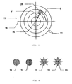
- Figure 2 illustrates the reference used to locate the threats 4 in the environment surrounding the building 3.
- a polar reference centered on the building 3 is advantageously used.
- the origin of the marker is permanently placed at the level of the building 3, even when the latter moves.
- a threat 4 located at a point in the space is marked by the indication of two angles: site S (angle marked with respect to the horizontal plane) and bearing G (angle identified with respect to a given direction, by example a vehicle mark), and a distance D between the threat 4 considered and the building 3.
- Some detection means 5 allow to know the distance D between a threat 4 and the building 3.
- Others only allow to know the site angles S and deposit G.
- the response means 6, when they are not omnidirectional, are characterized by a direction of action.
- the human machine interface 2 object of the invention focuses on a location and site location.
- a threat 4 is mainly identified by its location in the direction, namely its site S and its deposit G relative to the building 3.
- An essential characteristic of the human machine interface 2 which is the subject of the present invention is the use of a rosette 11 for mapping the spatial environment of the building 3.
- a rosette 11 is made of a diagram in plane polar coordinates.
- a point is indicated by a distance at origin 76 also called radius r and by an angular argument also called angle ⁇ .
- One of the important characteristics of the invention is to correspond to a direction of the surrounding space of the building 3 respectively marked in site S and in the field G, a point of said diagram, respectively marked by a radius r and an angle ⁇ .
- a circle or portion of a circle 77 concentric at the origin 76 represents directions of the environment having the same angle of elevation S.
- a straight line or segment 78 passing through the origin 76 represents directions of the environment with the same bearing angle G.
- These (portions of) circles 77 and these (segment of) straight 78 can respectively be graduated in angular measurement site and deposit. These measurements can be expressed in any angular unit (radians, gons, thousandths, degrees, ).
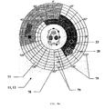
- Figures 8a, 8b, 9 show an embodiment in degrees. The reference elements that constitute these circles 77 and these lines 78 are advantageously regularly spaced. It is the same for the digital graduations 79.
- FIG. 8a illustrates for example a spacing of 10 ° for the circles 77 and 20 ° for the associated graduations 79 and a spacing of 15 ° for the straight lines 78 and 30 ° for the associated graduations 79.
- the direction of marking of the angles of deposit can be with the hourly or trigonometric choice.
- the figures show a partially hourly representation (from 0 ° to 180 °) and partially trigonometric (from -180 ° to 0 °).
- the origin (0 °) of the measurements is advantageously confused with the top of the diagram. This origin coincides with that adopted for the control of the displacement of the building 3 in that the 0 ° deposit is coincident with the longitudinal axis of the building 3 oriented towards the front.
- a threat 4 detected is at least known by its location in the S site and in the G-shaped field. It is thus possible to represent the location of such a threat 4 on the diagram of the rosette 11 of the man-machine interface 2 in the located at the point of the diagram corresponding to this angle of elevation S and this bearing angle G.
- a graphic symbol 20 is placed at the point of the diagram.
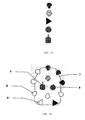
- Figure 4 illustrates examples of usable graphical symbols.
- the graphic symbol 20 may be a circle 21, a sun 22 or any other symbol. The color of this symbol may vary. It can be displayed in fixed or flashing mode.
- Figure 8a shows an example of a graphic symbol 20 overwritten with an "LTD" label 23.
- the graphic shape or attributes of this graphic symbol 20 may be indicative of other known attributes of the threat 4.
- the color , the form or wording 23 over-printed used may be the type of the threat.
- Other attributes of the threat may be figured.
- the color can indicate if the threat is a friend or an enemy.
- a threat 4 appears following detection by a detection means 5 and can be produced by another friendly building. This is for example a laser beam or a pointing of an optics made by a friendly building that is detected by the detection means 5 of the building 3.
- the wording 23 may, for example, indicate in real time, when known, the distance between the threat 4 and the building 3.
- a color change may also indicate a variation in the distance, or the state of the the threat: active, inactive, armed, fixed, mobile, destroyed, ...
- the flashing is, as described in the method, advantageously used to indicate a new threat 4 recently detected, its display becoming permanent when the detection of the threat 4 is confirmed or disappearing when threat 4 detection is canceled.
- FIG. 5a shows a detection means 5.
- This detection means 5 allows a useful detection in part of the environment of the building 3 that is designated detection area 24 and which characterizes the detection means 5.
- the area of detection 24 is limited by an area that can be circumscribed by two extreme angles of elevation SMIN and SMAX and by two extreme bearing angles GMIN and GMAX.
- Such a detection sector 24 can be represented on the diagram of the rosette 11 by a sector 24. corresponding as shown in Figure 5b.
- a response means 6 is characterized by a field of action 26 defined by the vision sensor associated with the weapon, which can be defined by two extreme angles of elevation SMIN and SMAX and two angles of extreme deposits GMIN and GMAX.
- a field of action 26 of a response means 6 can be represented on the diagram of the rosette 11 by a corresponding sector 26 as shown in Figure 5b.
- the angle GMIN may be equal to the angle GMAX.
- the representation sector 24, 26 on the rosette 11 is then a ring.
- Such a sector 24, 26 is advantageously filled with a clean color associated with the detection means 5 or by means of riposte 6.
- a color is defined here as a graphic pattern which may be a color, a gray pattern, a hatch pattern or any other identifiable uniform texture having identical display characteristics. The choice of this color is made so as to highlight the different detection areas 24 of the different detection means 5 and / or the different fields of action 26 of the different response means 6, with respect to each other.
- the display order or priority is advantageously chosen such that it limits the masking of one sector or field 24, 26 by another.
- a small sector 24, 26 is advantageously displayed above another sector 24, 26 more extensive.
- the display of the various sectors or fields 24, 26 on the rosette 11 is dynamic in that it is updated in time to correspond to an evolution of the configuration / position of the detection means 5 or the means 6. For example, for a detection means 5 having a detection sector 24 limited in the field but mobile in the field by means of a cupola, the representation of the detection area 24 on the rosette 11 moves on the diagram. agree with the rotation of said cupola.
- Some detection means 5 are mobile. This mobility is in site and / or in the field, for example by mounting said means on a cupola. Such an arrangement may make it possible, despite a detection sector 24 or a reduced field of action 26, to extend the useful zone of detection or action.
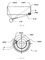
- Figures 6a and 6b illustrate the case of a gun type gun turret 45. Such a response means 6 has a reduced field of action 26.
- the useful area is extended to the whole of a template 27 of the weapon 45.
- This template 27 includes all the angular positions in site and in the field that can take the weapon 45.
- This template 27 is a sector of space limited by two extreme angles in SMIN and SMAX site and by two extreme angles in the GMIN and GMAX fields.
- the current position of the weapon 45 is dynamically represented by its field of action 26 and evolves as the weapon 45 moves.
- the template is represented by a fixed outline 27.
- This contour 27 is advantageously represented on the rose by a thickened line. This allows an operator to perceive, on the same display diagram, the current position of a detection or response means 6 and its complete operation domain represented by the template 27.
- One of the essential interests of the unified representation using the rosette 11 is to allow superimposing: the threats 4, the detection means 5 and the response means 6 combined with their possible templates 27. This allows a single at a glance to verify that a response is able to respond to a threat. Indeed, if a threat 4 is located outside the field of action 26 of a fixed riposte means 6 or outside the template 27 of a mobile riposte means 6, this means of riposte 6 is inoperative against said threat 4.
- the human machine interface 2 proposes tools making it possible to control the detection means 5 or the response means 6.
- each detection means 5 is associated with each detection means 5 a graphical representation 8 and each of these response means 6 is a graphic representation 9.
- These active graphic representations 8, 9 are said to be active in that they make it possible to designate and control the corresponding means 5, 6. This is for example achieved by means of a touch screen for producing a graphical display that can be used as a designation or control member.
- These active graphical representations 8, 9 are advantageously represented superimposed on a graphical representation 7 of the building 3.
- An advantageous embodiment consists of representing the building 3 by a schematic plan seen from above, on which the graphical representations 8, 9 means 5, 6 substantially in place on said plane that the means 5, 6 they represent occupy the actual building 3.
- graphical representations 8, 9 means 5, 6 substantially in place on said plane that the means 5, 6 they represent occupy the actual building 3.
- a given form is associated with a type of detection means 5 or riposte 6.
- a video camera can be represented by a semicircle and a panoramic viewfinder by an arrow circle.
- FIG. 7b shows an embodiment with a schematic graphical representation of the building 3, reduced to an outline showing the shape of the building 3.
- this graphical representation 7 are superimposed the graphical representations 8, 9 of various detection means 5 or riposte 6 in the place they occupy on the building 3.
- a single color is associated in each case with each detection means 5 or with each riposte means 6. This color is used for the graphic representation 8, 9 of said means 5, 6.
- the color used for the graphical representation 8, 9 of the means 5, 6 is the same as that used to represent on the escutcheon 11 its detection sector 24 or its field of action 26.
- the rosette 11 advantageously has an annular shape and frees a free space at its center.
- This space is not conducive to a representative display of the environment, the progressive reduction of space corresponding to a sector of the environment no longer allowing a sufficiently accurate display.
- This space left free is advantageously used to place there, as illustrated in FIGS. 8a, 8b or 9, the graphic representation 7 of the building 3, the graphic representations 8 of the detection means 5 and the graphic representations 9 of the response means 6.
- the graphical representation 7 indicates the orientation of said building 3 and makes it possible to distinguish the front of the rear.
- the graphical representation 7 of the building 3 is oriented in accordance with the orientation in the bearing of the rosette 11. The front of the building 3 is shown aligned with the 0 ° of the deposit.
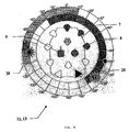
- the rosette 11 as represented in FIG. 9 has a reduced space for the superimposed representation of the graphical representations 7, 8, 9 of the detection means 5, the response means 6 and the building 3.
- the space dedicated to Rosette diagram allows to detail the position of a threat or the limits of a detection sector 24 or a field of action 26.
- This first rosette 12, adapted to the location information, is called rosace informative 12 or rosette of information.
- the rosette 11 of Figure 9 inverts the proportions.
- the central space and the graphical representations 7, 8, 9 have been greatly enlarged in order to separate them well and to make the different active graphical representations 7, 8, 9 appear, thus making it possible to select one of them, using a means of designation (mouse, joystick, finger ...) without risk of confusion between two neighboring graphical representations.
- This is done to the detriment of the rosette diagram which, represented on a smaller space is compressed in the radial direction corresponding to the direction of the site. This compression is done without loss of information. All indications, both threat 4 and detection area 24 or field of action 26 are still present.
- the detection means integrated in the system 1 may include any imager, sensor or measuring means for obtaining information on the objects of the environment. In the context of an application on a military building, these means are particularly directed towards the detection, recognition and identification of objects that may constitute potential threats.
- These detection means 5 may comprise one or more video cameras 30.
- the detection means 5 may comprise a viewfinder 31 or any similar optical device
- a response means 6 may be a rangefinder 40.
- the rangefinder 40 allows to aim at an object of the environment, likely to constitute a threat 4, to measure the distance separating said threat 4 from the building 3. This measure of distance makes it possible to specify the position of the said threat 4 in order, if necessary, to prepare a riposte.
- Another response means 6 is a smoke generator 43. Such a fumigant 43 produces a large amount of smoke that disturbs the enemy detection, observation or measurement means in order to protect the building 3. This means is implemented by triggering a pyrotechnic cartridge.
- Such pyrotechnic cartridges can be arranged in several positions distributed over the building 3.
- the operator can then advantageously take advantage of the indications of location of the threat 4 in order to trigger the most appropriate cartridge, that is to say in this case, that which will produce a cloud of smoke between the building 3 and the threat 4.
- the advantage of superimposing the location of the threat 4 on a rosette 11 having a graphic representation 9 of the response means 6, including the smoke 43, appearing their location on a graphical representation 7 of the building 3, on the same display appears here clearly.
- response means 6 are directional. They therefore need to be oriented, before their use, towards the threat 4. This can be achieved using a rally.
- Another means of response 6 may be a means of neutralizing the threat such as a weapon 45.
- a building 3 equipped with a system 1 according to the invention may be provided with one or more weapons 45. used, such a weapon 45 must before the shooting be oriented towards the threat 4. For this it is advantageously mounted on a turret or mobile turret in site and in relation to the building 3.
- the orientation of the weapon 45 by mobilization in the field and in the field of its turret / turret in order to point it towards the threat 4, can be carried out under the control of the system 1, by using a homing or servo-control function based on the direction in which is detected the threat 4 or the direction of the detection means 5 having detected the threat 4.
- the man-machine interface 2 advantageously comprises a control means 10.
- This control means 10 comprises means 50 for controlling actions of the interface. These actions comprise functions that can be performed by the detection means 5 or the response means 6 among which are comprised: CANCEL DETECTION 51, CONFIRM DETECTION 52, RECOPIER 53, RALLIER 54, ASSIGN 55, DEBRAYER 56 and dialogue or control functions of the interface 2, among which ZOOM 57, VALIDATE 58 and CANCEL 59 are included.
- the control means 10 may be a keyboard or a desk, each means 50 of which is to be controlled by a key associated with a command 51 to 59.
- control means 10 may also be a touch screen. FIG.
- each means 50 is recognizable in that it includes a wording 51 to 56, 58, 59 corresponding to the associated action or a pictogram, such as A magnifying glass for the ZOOM action 57.
- a pictogram such as A magnifying glass for the ZOOM action 57.
- the use of these means 50 for controlling actions 51 to 59 of the control means 10 is detailed later in the description of the methods of use of the interface 2.
- a layer may comprise the information relating to a detection means 5 or a response means 6: its graphic representation 8, 9, its detection area 24 or its field of action 26 and, if appropriate, its template 27. L activating such a layer causes all these elements to be displayed. Deactivation makes them disappear.
- a layer can thus be associated with all the graphic threat symbols or only with those of a certain type (friend / foe or by type of detection means, etc.).
- a layer can also be associated with the graduations 79 of the diagram of the rosette 11, 12, 13 or a grid of this same diagram. These different layers are selected by an operator by means of, for example, a second control means similar to the control means 10. Each layer is associated with a key of the second control means. A first press on the key displays the content of the layer whereas alternately a second key press deletes the said contents of the layer. Thus the operator can freely compose, at any moment, the display that suits him by showing the layers corresponding to the relevant information and hiding the layers that unnecessarily overload the display.
- the graphic representation 7 of the building 3, the active graphic representation 8 of the detection means 5, the active graphic representation 9 of the response means 6, the control means 10 and the rosette or rosettes 11, 12, 13 are made by means of a touch screen.
- a touch screen makes it possible to combine the display of information, with the attributes (color, blinking, updating, ...) necessary and the realization of commands superimposed with a graphical representation. It is appropriate to call active such graphic representations to control.
- the system 1 is on standby, its detection means 5 are on alert to detect, each in its field, the appearance of a threat 4. This occurrence occurs following the entry of a threat 4 in the detection area 24 of at least one detection means 5. This is consecutive to the movement of the threat 4 or the building 3.
- the detection means 5 detects the threat 4, measures the parameters of said threat 4 and transmits to the system 1 a detection information comprising the type and said parameters (site, field, distance, friend / enemy, ...) of said threat 4.
- the human machine interface 2 processes this information and displays on the diagram of the rosette 11 a graphic symbol 20 corresponding to the type of threat and the parameters.
- the interface 2 displays on the rosette 11 a sun overloaded with a label "LTD", located at the site and deposit of the rosette 11 corresponding to the angles of site and deposit detected.
- LTD label
- the sun can be displayed YELLOW at first to appear a NEUTRAL threat (waiting for its classification between AMI and ENNEMI). It may also be flashing to alert the operator that this threat has recently appeared pending CONFIRMATION DETECTION or CANCELLATION DETECTION.
- This display can, in the case of a critical threat 4, be redundant by the emission of an audible signal by the interface 2.
- the interface 2 is then placed waiting for a control action of the operator.
- the man-machine interface 2 erases the graphic symbol 20 corresponding to the threat 4 chosen. If this threat 4 had previously been accompanied by the emission of an audible signal and this signal continues, the interface 2 stops the transmission of this sound signal.
- the operator can opt for a threat detection confirmation 4.
- the operator activates the CONFIRM DETECTION action 52 by the appropriate key of the control means 10.
- the operator designates the threat 4 that he wishes to confirm among those displayed on the rosette 11 by actuating its active graphic symbol 20 on the rosette 11.
- the operator then confirms his command advantageously by pressing the VALIDATE key 58 of the control means 10.
- the human machine interface 2 stops the flashing and displays in fixed mode the graphic symbol 20 corresponding to the threat 4 chosen.
- the display of the graphic symbol 20 is located on the rosette in site and bearing corresponding to its position in the environment. This location is updated regularly according to any new detections made.
- the operator can control some of the detection means 5 or some of the response means 6 by means of actions making it possible to control the behavior of these means 5 , 6.
- the operator can thus RECOPIER 53, RALLIER 54, SERVE 55 or DEBRAYER 56.
- the action RECOPIER 53 applies to an image detection means 5, for example a camera.
- a camera for example a fixed or mobile camera is intended to provide an image whose content is analyzed by the operator.
- the latter has for displaying images, at least one display screen, one of which, predefined, is more particularly intended to receive the copied image.
- the operator has most often in a system 1 several cameras.
- the action RECOPIER 53 makes it possible to select which of these cameras is copied onto the predefined display screen.
- the operator controls the action RECOPIER 53 by means of the corresponding key of the control means 10. He then selects the desired camera by actuating the graphic representation 8 of this camera / detection means 5.
- the operator confirms advantageously its control by an action on the VALID key 58 of the control means 10.
- the human machine interface 2 transmits the copy order of the image of the camera to the predefined display screen.
- the action RALLIER 54 applies to a detection means 5 or to a mobile or multiple response means 6.
- Such a way 5, 6 is said mobile when orientable in site and / or in the field.
- Such means 5, 6 is said to be multiple when it consists of several complementary means. This is so with a crown of cameras whose fields complement each other.
- the rallying consists in this case to select the recipient camera (s) 62 aiming at best the direction indicated by the source means 61 among the cameras of the crown.
- the rallying of such a destination means 62, on another source means 61, which may be a means of detection or response, consists in moving the destination means 62 to coincide its orientation in site and / or in the field with that the source means 61.
- the operator controls the action RALLIER 54 by means of the corresponding key of the control means 10. He then selects the destination means 62 desired by actuating the graphical representation 8 of this means 62. He then selects the source means 61 desired by actuating the graphical representation 8 of this means 61.
- the source means 61 may be a moving or fixed means, as long as it indicates a direction, typically by its axis of sight.
- the operator then advantageously confirms his command by an action on the VALIDER key 58 of the control means 10. In response to this validation, the man-machine interface 2 transmits the rallying order of the destination means 62 to the on-site direction and or in the reservoir of the source means 61.
- the ASSERVE 55 action applies to a detection means 5 or to a mobile or multiple response means 6.
- a means 5, 6 is said to be mobile when it is orientable in site and / or in bearing.
- Such means 5, 6 is said to be multiple when it consists of several complementary means.
- rallying which is a one-time one-time action
- the slaving continues in time and a link is created between the source means 61 and the destination means 62.
- the recipient means 62 continues to move in order to to follow the movements of the medium source 61. For example, if an armed turret is enslaved on a mobile camera, the weapon remained permanently pointed towards what the camera sees.
- the operator who controls the movement of said camera indirectly controls in parallel the movement of the weapon, which remains permanently pointed towards what the operator observes via the camera.
- a riposte with the weapon can, if necessary, quickly be implemented as soon as the operator detects a threat by observing the video image from said camera.
- the slaving of a destination means 62, on another source means 61 consists of moving the destination means 62 to coincide its orientation in location and / or in register with that of the source means 61 and then to continue moving recipient means 62 so that its orientation remains in coincidence with that of the source means 61 at any time, even when the source means 61 moves.
- the operator controls the ASSERVE action 55 by means of the corresponding key of the control means 10.
- the man-machine interface 2 transmits the command servocontrol of the destination means 62 on the direction in site and / or in the reservoir of the source means 61. A servocontrol starts as a rallying, but the servo link between the source means 61 and the destination means 62 is maintained up to the counter order.
- a graphical representation of the servocontrol link is advantageously displayed by the human machine interface 2.
- This graphical representation 28 maps and relates the respective graphical representations of the source means 61 and the destination means 62.
- This graphical representation 28 can be a graphical figure 29 connecting the graphical representation of the recipient means 62 and the graphical representation of the means 61.
- This graphical figure 29 may be an outline surrounding together the two graphical representations 61, 62, a line joining the two graphical representations, an arrow or any other similar drawing showing a link between the two graphical representations.
- Figures 11a and 11b illustrate examples of use of a graphical figure 29 of type trait.
- this graphical representation 28 may be a symbol 29 ', made with the proper color associated with the source means 61, displayed superimposed on the graphical representation 62 of the destination means.
- This symbol may be a dot, a circle, a symbol in the form of the graphical representation 61 of the source means or any other symbol.
- Such a symbol 29 ' is chosen smaller than the graphic representation 61 so as not to mask the latter. It is, of course, possible to realize the opposite, namely a symbol 29 'of the color of the destination means 62 superimposed on the graphical representation 61 of the source means.
- Figures 11c and 11d illustrate examples of use of such symbols 29 '.
- the DEBRAYER 56 action is the counterorder of the ASSERVE action.
- the disengagement consists of deleting a servo link.
- the operator controls the DEBRAYER action 56 by means of the corresponding key of the control means 10. He then selects the source means 61 desired by actuating the graphical representation 8 of this means 61. The operator then advantageously confirms his command. by an action on the VALIDATE key 58 of the control means 10.
- the man-machine interface 2 transmits the disengagement command / end of the destination means 62 to the source means 61. It is possible to envisage to equally select the recipient means 62. If a graphical representation of the servo link existed, it is removed from the display accordingly.
- the man-machine interface 2 has two display modes: an information rosette 12 and a control rosette 13.
- the rosette information is more detailed and allows to display mainly information about the threats 4.
- the control rosette 13 which enlarges the central area and therefore the graphic representations 7 of the building, the detection means 8 and the response means 9 is more advantageous for carrying out a command and in particular for designating a detection means 5 or a riposte means 6.
- the passage of a rosette 12, 13 to the other is effected by an appropriate command of the control means 10: the ZOOM command 57.
- An action on this command 57 causes the display of the other rosette.
- the wording or the symbol represented on this command can advantageously change to reflect the taking into account of the command. It can for example display respectively a magnifying glass with a symbol "+" and a magnifying glass with a symbol "-".
- the method integrates a next automatic step.
- the default display is that of information rosette 12.
- the human machine interface 2 toggle the display on the control rosette 13. This prepares the immediately following operation of selecting a detection means 5 or riposte 6.
- the end of a sequence, marked by the action VALIDER 58 causes automatic display by the man-machine interface 2 of the information rosette 12.
- the invention also extends to any system 1 for dealing with threats 4 directed against a building 3 comprising a human machine interface 2 or a method according to any one of the preceding characteristics.
Landscapes
- Engineering & Computer Science (AREA)
- Computer Networks & Wireless Communication (AREA)
- Physics & Mathematics (AREA)
- General Physics & Mathematics (AREA)
- Radar, Positioning & Navigation (AREA)
- Remote Sensing (AREA)
- General Engineering & Computer Science (AREA)
- User Interface Of Digital Computer (AREA)
- Burglar Alarm Systems (AREA)
Applications Claiming Priority (1)
| Application Number | Priority Date | Filing Date | Title |
|---|---|---|---|
| FR0410066A FR2875613B1 (fr) | 2004-09-23 | 2004-09-23 | Interface homme machine d'un systeme de traitement de menaces |
Publications (2)
| Publication Number | Publication Date |
|---|---|
| EP1640740A2 true EP1640740A2 (de) | 2006-03-29 |
| EP1640740A3 EP1640740A3 (de) | 2006-09-20 |
Family
ID=34953293
Family Applications (1)
| Application Number | Title | Priority Date | Filing Date |
|---|---|---|---|
| EP05291954A Withdrawn EP1640740A3 (de) | 2004-09-23 | 2005-09-21 | Mensch-Maschine Schnittstelle eines Bedrohungsbearbeitungssystemes |
Country Status (2)
| Country | Link |
|---|---|
| EP (1) | EP1640740A3 (de) |
| FR (1) | FR2875613B1 (de) |
Cited By (2)
| Publication number | Priority date | Publication date | Assignee | Title |
|---|---|---|---|---|
| EP2131208A1 (de) * | 2008-06-03 | 2009-12-09 | Saab AB | Anzeigevorrichtung |
| FR2999725A1 (fr) * | 2012-12-18 | 2014-06-20 | Thales Sa | Procede de reglage d'un secteur de cision/masquage d'un dispositif de scrutation d'environnement, dispositif de reglage et terminal d'operateur correspondants |
Families Citing this family (2)
| Publication number | Priority date | Publication date | Assignee | Title |
|---|---|---|---|---|
| US7865836B1 (en) * | 2007-07-27 | 2011-01-04 | The United States Of America As Represented By The Secretary Of The Navy | Geospatial prioritized data acquisition analysis and presentation |
| FR3097651B1 (fr) * | 2019-06-20 | 2021-06-18 | Safran Electronics & Defense | Procédé de surveillance de l’environnement d’un véhicule |
Citations (2)
| Publication number | Priority date | Publication date | Assignee | Title |
|---|---|---|---|---|
| GB1605283A (en) * | 1973-10-01 | 1987-12-31 | Cossor Ltd A C | Vehicle identification |
| US5483865A (en) * | 1993-06-09 | 1996-01-16 | Eurocopter France | Aircraft sighting system |
Family Cites Families (8)
| Publication number | Priority date | Publication date | Assignee | Title |
|---|---|---|---|---|
| IL76817A (en) * | 1984-11-20 | 1991-06-10 | Hughes Aircraft Co | Indicating display of target deviations |
| DE3803893A1 (de) * | 1988-02-09 | 1989-08-17 | Siemens Ag | Verfahren zur radarbilddarstellung |
| CA2017331A1 (en) * | 1989-06-30 | 1990-12-31 | Jerry W. Huff | Three-dimensional perspective plan-view format for situation awareness displays |
| EP0855693A1 (de) * | 1997-01-24 | 1998-07-29 | Digital Equipment Corporation | System und Verfahren zur Darstellung blinkender Objekte auf einer Anzeigevorrichtung |
| FR2769699B1 (fr) * | 1997-10-10 | 1999-12-10 | Aerospatiale | Dispositif de guidage d'un engin volant, notamment un missile |
| US6211808B1 (en) * | 1999-02-23 | 2001-04-03 | Flight Safety Technologies Inc. | Collision avoidance system for use in aircraft |
| US6672534B2 (en) * | 2001-05-02 | 2004-01-06 | Lockheed Martin Corporation | Autonomous mission profile planning |
| DE10145641A1 (de) * | 2001-09-15 | 2003-04-10 | Krauss Maffei Wegmann Gmbh & C | Verfahren zur Erfassung einer Luftlage in einem Kampffahrzeug sowie Vorrichtung zur Durchführung des Verfahrens |
-
2004
- 2004-09-23 FR FR0410066A patent/FR2875613B1/fr not_active Expired - Lifetime
-
2005
- 2005-09-21 EP EP05291954A patent/EP1640740A3/de not_active Withdrawn
Patent Citations (2)
| Publication number | Priority date | Publication date | Assignee | Title |
|---|---|---|---|---|
| GB1605283A (en) * | 1973-10-01 | 1987-12-31 | Cossor Ltd A C | Vehicle identification |
| US5483865A (en) * | 1993-06-09 | 1996-01-16 | Eurocopter France | Aircraft sighting system |
Cited By (4)
| Publication number | Priority date | Publication date | Assignee | Title |
|---|---|---|---|---|
| EP2131208A1 (de) * | 2008-06-03 | 2009-12-09 | Saab AB | Anzeigevorrichtung |
| FR2999725A1 (fr) * | 2012-12-18 | 2014-06-20 | Thales Sa | Procede de reglage d'un secteur de cision/masquage d'un dispositif de scrutation d'environnement, dispositif de reglage et terminal d'operateur correspondants |
| WO2014095883A1 (fr) * | 2012-12-18 | 2014-06-26 | Thales | Procédé de réglage d'un secteur de vision/masquage d'un dispositif de scrutation d'environnement, dispositif de réglage et terminal d'opérateur correspondants |
| US9983762B2 (en) | 2012-12-18 | 2018-05-29 | Thales | Method for adjusting a viewing/masking sector of an environment scanning device, and corresponding adjusting device and operator terminal |
Also Published As
| Publication number | Publication date |
|---|---|
| FR2875613B1 (fr) | 2007-03-16 |
| EP1640740A3 (de) | 2006-09-20 |
| FR2875613A1 (fr) | 2006-03-24 |
Similar Documents
| Publication | Publication Date | Title |
|---|---|---|
| US10204454B2 (en) | Method and system for image georegistration | |
| US20200264696A1 (en) | Electronic Device Displays an Image of an Obstructed Target | |
| EP3019968B1 (de) | System und verfahren zum verarbeiten von taktischen informationen in kampffahrzeugen | |
| US10822110B2 (en) | Threat countermeasure assistance system | |
| NO20120341A1 (no) | Metode og anordning for å kontrollere og overvåke det omliggende område til et ubemannet luftfartøy | |
| KR20090034824A (ko) | 애플리케이션 제어 방법, 위치 정보 제공 시스템 및 컴퓨터판독가능 매체 | |
| EP1876413A2 (de) | Passiver optischer Lokalisator | |
| CN114930112B (zh) | 用于控制战斗车辆炮塔功能的智能系统 | |
| EP4296943A2 (de) | Verfahren und systeme zur 3d-kamerapositionsbestimmung | |
| EP1640740A2 (de) | Mensch-Maschine Schnittstelle eines Bedrohungsbearbeitungssystemes | |
| KR101076240B1 (ko) | 증강현실을 이용한 방공 전장상황 제공 장치 및 방법 | |
| CA2933954C (en) | Method, system and computer program for decision support | |
| KR101681530B1 (ko) | 함정전투체계의 전술금지구역 감시장치 | |
| EP3063550B1 (de) | Bedienerendgerät mitanzeige der zonen der bildaufnahmequalität | |
| EP2811465B1 (de) | Videoüberwachungssystem | |
| EP3529559A1 (de) | Verfahren zur unterstützung der position eines zieles und beobachtungsvorrichtung für die umsetzung dieses verfahrens | |
| EP1526733B1 (de) | Automatisches Verfahren zur Kontrolle der optischen Achsenausrichtung und des Blickfeldwinkels einer der elektronischen Kamera, insbesondere für die Videoüberwachung mit automatischer Zielverfolgung | |
| EP1688698B1 (de) | Verfahren zur Steuerung der Kapazitäten eines Plattforms und eine Vorrichtung zur Umsetzung des Verfahrens | |
| WO2007017599A1 (fr) | Dispositif d'entrainement au tir a partir d'une arme | |
| EP4064010B1 (de) | Verfahren und system zur visualisierung und verwaltung einer situation in der umgebung eines luftfahrzeugs | |
| FR2929700A1 (fr) | Dispositif decentralise d'autodefense comprenant un pointeur portable et mobile apte a assurer en urgence la defense rapprochee d'un navire ou d'une plate-forme en mer contre une menace de surface. | |
| Vyshak et al. | Hive Destruction Protocol: An Automated Defense System Utilizing YOLO Human Recognition and Real-Time GPS Tracking | |
| CA2919787A1 (fr) | Systeme de programmation d'un systeme d'analyse de situation embarque sur un porteur comportant au moins un systeme d'ecoute embarque | |
| FR2926143A1 (fr) | Procede de veille et de detection de cibles, notamment mobiles, pour une plate-forme et dispositif mettant en oeuvre un tel procede | |
| GB2585447A (en) | Imaging systems including real-time target-acquisition and triangulation features and human-machine interfaces therefor |
Legal Events
| Date | Code | Title | Description |
|---|---|---|---|
| PUAI | Public reference made under article 153(3) epc to a published international application that has entered the european phase |
Free format text: ORIGINAL CODE: 0009012 |
|
| AK | Designated contracting states |
Kind code of ref document: A2 Designated state(s): AT BE BG CH CY CZ DE DK EE ES FI FR GB GR HU IE IS IT LI LT LU LV MC NL PL PT RO SE SI SK TR |
|
| AX | Request for extension of the european patent |
Extension state: AL BA HR MK YU |
|
| PUAL | Search report despatched |
Free format text: ORIGINAL CODE: 0009013 |
|
| AK | Designated contracting states |
Kind code of ref document: A3 Designated state(s): AT BE BG CH CY CZ DE DK EE ES FI FR GB GR HU IE IS IT LI LT LU LV MC NL PL PT RO SE SI SK TR |
|
| AX | Request for extension of the european patent |
Extension state: AL BA HR MK YU |
|
| RAP1 | Party data changed (applicant data changed or rights of an application transferred) |
Owner name: NEXTER SYSTEMS |
|
| 17P | Request for examination filed |
Effective date: 20070228 |
|
| 17Q | First examination report despatched |
Effective date: 20070412 |
|
| AKX | Designation fees paid |
Designated state(s): AT BE BG CH CY CZ DE DK EE ES FI FR GB GR HU IE IS IT LI LT LU LV MC NL PL PT RO SE SI SK TR |
|
| STAA | Information on the status of an ep patent application or granted ep patent |
Free format text: STATUS: THE APPLICATION HAS BEEN WITHDRAWN |
|
| 18W | Application withdrawn |
Effective date: 20190720 |