EP1526733B1 - Automatisches Verfahren zur Kontrolle der optischen Achsenausrichtung und des Blickfeldwinkels einer der elektronischen Kamera, insbesondere für die Videoüberwachung mit automatischer Zielverfolgung - Google Patents
Automatisches Verfahren zur Kontrolle der optischen Achsenausrichtung und des Blickfeldwinkels einer der elektronischen Kamera, insbesondere für die Videoüberwachung mit automatischer Zielverfolgung Download PDFInfo
- Publication number
- EP1526733B1 EP1526733B1 EP04292502A EP04292502A EP1526733B1 EP 1526733 B1 EP1526733 B1 EP 1526733B1 EP 04292502 A EP04292502 A EP 04292502A EP 04292502 A EP04292502 A EP 04292502A EP 1526733 B1 EP1526733 B1 EP 1526733B1
- Authority
- EP
- European Patent Office
- Prior art keywords
- camera
- image
- variation
- angular field
- control process
- Prior art date
- Legal status (The legal status is an assumption and is not a legal conclusion. Google has not performed a legal analysis and makes no representation as to the accuracy of the status listed.)
- Expired - Lifetime
Links
- 238000000034 method Methods 0.000 title claims abstract description 35
- 230000003287 optical effect Effects 0.000 title claims abstract description 23
- 230000033001 locomotion Effects 0.000 claims abstract description 18
- 238000004458 analytical method Methods 0.000 claims abstract description 12
- 238000005070 sampling Methods 0.000 claims abstract description 6
- 230000008569 process Effects 0.000 claims description 17
- 230000006870 function Effects 0.000 claims description 12
- 238000009432 framing Methods 0.000 claims description 5
- 230000000750 progressive effect Effects 0.000 claims description 4
- 230000035807 sensation Effects 0.000 claims description 2
- 238000006073 displacement reaction Methods 0.000 description 9
- 238000012544 monitoring process Methods 0.000 description 6
- 230000008859 change Effects 0.000 description 5
- 238000001514 detection method Methods 0.000 description 5
- 238000009434 installation Methods 0.000 description 5
- 238000012545 processing Methods 0.000 description 5
- 238000010191 image analysis Methods 0.000 description 3
- 206010003830 Automatism Diseases 0.000 description 1
- 230000009471 action Effects 0.000 description 1
- 230000006978 adaptation Effects 0.000 description 1
- 238000013459 approach Methods 0.000 description 1
- 230000005540 biological transmission Effects 0.000 description 1
- 210000004556 brain Anatomy 0.000 description 1
- 239000003086 colorant Substances 0.000 description 1
- 238000004891 communication Methods 0.000 description 1
- 230000000881 depressing effect Effects 0.000 description 1
- 238000012986 modification Methods 0.000 description 1
- 230000004048 modification Effects 0.000 description 1
- 230000011514 reflex Effects 0.000 description 1
- 230000001960 triggered effect Effects 0.000 description 1
Images
Classifications
-
- H—ELECTRICITY
- H04—ELECTRIC COMMUNICATION TECHNIQUE
- H04N—PICTORIAL COMMUNICATION, e.g. TELEVISION
- H04N7/00—Television systems
- H04N7/18—Closed-circuit television [CCTV] systems, i.e. systems in which the video signal is not broadcast
- H04N7/183—Closed-circuit television [CCTV] systems, i.e. systems in which the video signal is not broadcast for receiving images from a single remote source
-
- H—ELECTRICITY
- H04—ELECTRIC COMMUNICATION TECHNIQUE
- H04N—PICTORIAL COMMUNICATION, e.g. TELEVISION
- H04N23/00—Cameras or camera modules comprising electronic image sensors; Control thereof
- H04N23/60—Control of cameras or camera modules
- H04N23/63—Control of cameras or camera modules by using electronic viewfinders
- H04N23/633—Control of cameras or camera modules by using electronic viewfinders for displaying additional information relating to control or operation of the camera
- H04N23/635—Region indicators; Field of view indicators
Definitions
- the present invention generally relates to video surveillance techniques, and more specifically, it relates to the automatic control of the direction of the optical axis and the angular field of a steerable electronic camera with variable angular field, giving an image that can be displayed on a screen.
- the document EP-1 107 584 relates to a device which follows displacements defined from predetermined positions and settings, without a general relationship between the direction and the angular field.
- Installations are also known which include steerable electronic cameras, generally along two axes perpendicular to each other, under the control of a joystick.
- a person in charge of monitoring having one or more controllers and one or more screens each displaying one or more images, can control the direction and the angular field of each camera.
- this person changes the direction of the optical axis of the camera.
- cameras controlled by a joystick are known in which the control of the displacement of the optical axis is carried out in a relation such that the speed of displacement of the optical axis is smaller when the angular field is small, as described. in EP-0966155.
- the user of a joystick is obliged to simultaneously perform the function of a very experienced operator for the operation of the joystick (direction and magnification), and the function of an observer of the framing image variable displayed the associated unique screen. If the operation of the joystick is excessively fast, the user can lose the feeling of continuity of the displacement of the image, and he does not know what part of the monitored premises he sees on the screen. He must control the joystick in a progressive way adapted to the image particular displayed. Since its operator function is slaved to its observer function, it is not possible for it to simultaneously observe images on other screens. This ignorance of these other images, and therefore of other events, and this enslavement, put him under stress.
- Another disadvantage is that the user can control only one gamepad at a time, and can only monitor one location at a time (a single image) when moving the joystick.
- the object of the invention is to remedy the disadvantages of these known game controller installations which require a great expertise of its users.
- the invention applies this phenomenon the automation of the control of monitoring facilities.
- the invention relates to the automatic control, without joystick, the direction of the optical axis and the angular field of an electronic camera.
- the method of the invention allows a progressive framing on the one hand and a suitable enlargement of the image on the other hand such that a sensation of continuity is automatically obtained by the observer , thanks to the use of a speed of displacement which is related to the angular field of the camera.
- the invention relates to a method for automatically controlling the direction of the optical axis and the angular field of a steerable electronic camera with variable angular field giving an image that can be displayed on a screen, of the type that includes the determining a target direction, controlling the direction of the optical axis of the camera so that it approaches the target direction, and adjusting the angular field of the camera; according to the invention, the control of the direction of the optical axis towards the target direction and the adjustment of the angular field of the camera are executed in a relation such that the speed of variation of the steering control is smaller when the field angular is small, and the control process begins to be executed when an event has occurred in the angular field of the camera.
- the relationship between the rate of change of the steering control and the angular field is determined by selection by the user.
- the relationship is determined by selecting a maximum speed for at least one determined angular field.
- the relationship depends on an additional global or extended parameter of the image, such as its brightness.
- the adjustment of the angular field of the camera is achieved by varying the focal length of a camera lens.
- the adjustment of the angular field is performed by digital processing of the camera signal.
- the camera has an automatically controlled zoom
- the event triggering the control method is the operation of the automatically controlled zoom.
- the event triggering the control method is the variation of the luminance or chrominance signal at least of the electronic camera.
- control method begins to be executed when a new target direction is determined.
- the determination of the target direction is performed by indicating a location on the screen.
- the indication of a location on the screen can be done by pointing, for example with a mouse or on a touch screen.
- the determination of the target direction is performed by indicating coordinates of a location on the screen.
- the determination of the target direction is performed by analyzing the camera image with reference to the variation of a luminance or chrominance component of at least a portion of the at least one part of the camera. picture of the camera.
- the analysis comprises determining the greatest variation among the determined variations in at least four regions disposed around the center of the image, and orienting the target direction to a region of greater variation.
- the determination of the greatest variation can be made by determining the variation at several points aligned on a grid.
- the camera gives a color image
- the analysis is performed on a single color channel of the camera signal.
- the analysis is done on the green color channel.
- the method is at least partially executed by a software module having a "multi-protocol" function.
- the camera it is advantageous for the camera to be rotatable about two perpendicular axes.
- the invention relates to the field of video surveillance using an automatic control method for enabling the observation and / or recording of images representing all movements in a monitored extended region. It allows an automatic tracking of all movements in this area.
- the purpose of CCTV includes first detecting the presence of a moving subject in a monitored area, and then automatically tracking the subject in that area, with observation and / or recording. For this observation and / or this recording to be optimal, it is essential that the framing and the magnification are optimized.
- the invention relates to a method of automatic control, particularly tracking, which ensures both such an optimized framing and obtaining an optimized magnification.
- the monitoring begins with the detection of a movement in the monitored area, i.e. in the image of the camera.
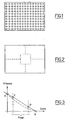
- the Figures 1 and 2 illustrate an example of determining a movement.
- the figure 1 represents a sampling grid; at each point, a parameter derived from a luminance and / or chrominance signal of the camera is, for example, averaged at each of the sampling points indicated on the figure 1 .
- a parameter derived from a luminance and / or chrominance signal of the camera is, for example, averaged at each of the sampling points indicated on the figure 1 .
- the motion can be detected by processing the samples of the grid points contained in each of the regions at the four corners of the image frame indicated on the figure 2 .
- a weighting can be introduced on the value of each point.
- a central part or "dead zone” is not taken into account and limits the insignificant movements of the cameras.
- This simple arrangement in four regions makes it possible to determine which of these four zones in which the variation of the processed signal is the greatest. This determination is used to control a displacement of the optical axis of the camera towards the region indicating the greatest displacement.
- This move operation can be executed until, given a threshold value, there is a balance between the four regions.
- the signal comprises twenty-four bits, the higher order bits being reserved for blue, the eight intermediate bits for red and the eight bits for green. If the processed channel is the blue or red channel, a shift of the video signal is necessary for the selection of suitable bits. If the processed channel is the green channel, no offset is needed, and all that is required is to keep the eight lower order bits. It is conceivable that the digital processing can thus be accelerated, that is to say that the necessary computing power can be reduced.
- the camera is arranged in a "dome" of a type well known in the art, in which the camera can be oriented in two directions. perpendicular axes, usually a horizontal axis and a vertical axis.
- the camera frequently includes continuously variable zoom optics, called zoom, with automatic focusing control.
- this determination of the target direction can be performed differently. For example, in a simple case, it is possible to indicate a location on the screen. This location may be designated by a pointing device, for example a mouse, or by contact with a touch screen that displays the image of the camera. It is also possible to determine the target direction by indicating coordinates of a location of the screen, by any means, even by input with a keyboard.
- the first embodiment described is more interesting because it is automatic: the determination of the target direction is done by analyzing the image of the camera, by determining the variations of a luminance or chrominance component.
- the automation is integral, since no operator function is necessary: the supervisor can devote himself to his only observation task which can then cover several screens, without being in a stress situation .
- the invention therefore has the important advantages of reducing the stress of the supervisors of a video surveillance system and increasing their monitoring possibilities.
- the triggering of the automatic control method was carried out by permanent analysis of the image and determination of an imbalance between the different regions of the image.
- the control method may be triggered by another event.
- this event occurs in the angular field of the camera.
- image analysis for determining an event.
- the event is not always the determination of a movement in an off-center part of the screen, because it can be simply the change of a global parameter of the image, for example its brightness.
- the triggering of the command may also be the result of an event that is not related to the content of the image, but to its form.
- the surveillance domes usually include a zoom with automatic focus control.
- the event that triggers the control process may be the operation of this zoom, that is to say a change in its setting.
- An essential feature of the invention is the relationship between the speed of movement of the optical axis of the camera and the size of the angular field. Not all individuals are equally sensitive to the rate of change in the direction of the optical axis as the angular field changes. It is therefore desirable that the relationship can be adapted to the particular user, preferably by the user himself.
- the figure 3 illustrates a possibility of such an adaptation of the relation between the speed of variation of the direction of the optical axis and the angular field.
- the figure 3 is a speed-focal length zoom chart.
- I1 indicates by the line in full line an example of relation between the speed of displacement of the optical axis and the adjustment of the zoom, that is to say the focal length of this one.
- the indicated range represents the limits of variation of the focal length.
- the user can for example determine the two points A and B, or both points C and D, the system then determining the line that connects them.
- the relationship depends on an additional global or extended parameter of the image, for example its brightness, so that it is well adapted to the physiological reactions of the eye and the vision system.
- the method of the invention is partially executed by a software module that is programmable and adaptable to numerous monitoring dome management protocols from different providers.
- the same module is suitable for many different domes of which only the basic functions of orientation control and field setting can be used.
- Transmission of data exchanged with a dome is advantageously carried out by telemetry, for example by an RS485 bus.
- the necessary information can be transmitted to the dome via simplex (two-wire) communication.
- This software module the time between image analysis and dome action is extremely short.
- This "multi-protocol" function of the software module is extremely useful because it allows a simple and progressive evolution of the installation used, for example during the exchange or replacement of one or more domes of the same type or types. different, and when increasing or reducing the extent of the area being monitored.
Landscapes
- Engineering & Computer Science (AREA)
- Multimedia (AREA)
- Signal Processing (AREA)
- Closed-Circuit Television Systems (AREA)
- Studio Devices (AREA)
Claims (11)
- Verfahren zur automatischen Kontrolle der Ausrichtung der optischen Achsen und des Blickfeldwinkels einer steuerbaren elektronischen Kamera mit verstellbarem Blickfeldwinkel, welche ein Bild liefert, das auf einem Bildschirm gezeigt werden kann, vom Typ mit:dem Durchführungsbeginn des Kontrollverfahrens,der Bestimmung einer Zielrichtung,der Kontrolle der Ausrichtung der optischen Achsen der Kamera, damit sie sich der Zielrichtung nähert, undder Einstellung des Blickfelelwinkels der Kamera,wobei sich die Kontrolle der Ausrichtung der optischen Achsen zur Zielrichtung hin nach einer Relation (A, B, C, D) derart vollzieht, dass die Geschwindigkeit der Veränderung der Richtungskontrolle kleiner ist, wenn der Blickfeldwinkel klein ist,dadurch gekennzeichnet, dassder Durchführungsbeginn des Kontrollverfahrens automatisch erfolgt, wenn in dem Blickfeldwinkel der Kamera ein Ereignis eingetreten ist,die automatische Kontrolle der Ausrichtung der optischen Achsen zur Zielrichtung hin und die Einstellung des Blickfeldwinkels der Kamera nach einer Relation (A, B, C, D) derart ausgeführt werden, dass die Geschwindigkeit der Veränderung der Richtungskontrolle kleiner ist, wenn der Blickfeldwinkel klein ist, wobei diese Relation für den Benutzer derart adaptionsfähig ist, dass man einerseits eine progressive Bildeinstellung und andererseits eine Vergrößerung des Bildes erhält, so dass durch den Benutzer automatisch eine kontinuierliche Wahrnehmung erhalten wird.
- Verfahren nach Anspruch 1, dadurch gekennzeichnet, dass ein Gitter zur Probenahme der Kamera benutzt wird, wobei ein zentraler Teil dieses Gitters nicht berücksichtigt wird und erlaubt, die nicht signifikanten Verschiebungen der Kamera zu begrenzen.
- Verfahren zur automatischen Kontrolle nach Anspruch 1 oder 2, dadurch gekennzeichnet, dass die Relation (A, B, C, D) durch Auswahl von dem Benutzer bestimmt wird.
- Verfahren zur automatischen Kontrolle nach einem der Ansprüche 1 bis 3, dadurch gekennzeichnet, dass die Einstellung des Blickfeldwinkels der Kamera durch Veränderung der Brennweite eines Objektivs der Kamera realisiert wird.
- Verfahren zur automatischen Kontrolle nach einem der vorhergehenden Ansprüche, dadurch gekennzeichnet, dass das Verfahren mindestens teilweise durch ein Softwaremodul durchgeführt wird, welches eine "Multiprotokoll"-Funktion hat.
- Verfahren zur automatischen Kontrolle nach einem der vorhergehenden Ansprüche, dadurch gekennzeichnet, dass das die Kontrolle auslösende Ereignis die Verbänderung eines Signals ist, das mindestens unter den Luminanzsignalen und den Chrominanzsignalen der elektronischen Kamera ausgewählt ist.
- Verfahren zur automatischen Kontrolle nach einem der vorhergehenden Ansprüche, dadurch gekennzeichnet, dass die Bestimmung der Zielrichtung durch Analyse des Bildes der Kamera unter Bezug auf die Veränderung einer Luminanz- oder Chrominanzkomponente mindestens eines Teils mindestens des Bildes der Kamera erfolgt.
- Verfahren zur automatischen Kontrolle nach Anspruch 7, dadurch gekennzeichnet, dass die Analyse die Bestimmung der größten Veränderung unter den vorbestimmten Veränderungen in mindestens vier um das Zentrum des Bildes angeordneten Bereichen und die Orientierung der Zielrichtung zu einem Bereich der größten Veränderung hin aufweist.
- Verfahren zur automatischen Kontrolle nach Anspruch 8, dadurch gekennzeichnet, dass die Bestimmung der größten Veränderung durch die Bestimmung der Veränderung an mehreren auf einem Gitter in Reihe angeordneten Punkten durchgeführt wird.
- Verfahren zur automatischen Kontrolle nach einem der Ansprüche 7 bis 9, dadurch gekennzeichnet, dass die Kamera ein farbiges Bild liefert und die Analyse auf einem einzigen Farbkanal des Signals der Kamera erfolgt.
- Verfahren zur automatischen Kontrolle nach Anspruch 10, dadurch gekennzeichnet, dass die Analyse auf dem Kanal der Farbe grün erfolgt.
Applications Claiming Priority (2)
| Application Number | Priority Date | Filing Date | Title |
|---|---|---|---|
| FR0312298 | 2003-10-21 | ||
| FR0312298A FR2861204B1 (fr) | 2003-10-21 | 2003-10-21 | Procede de commande automatique de la direction de l'axe optique et du champ angulaire d'une camera electronique, notamment pour videosurveillance par poursuite automatique |
Publications (2)
| Publication Number | Publication Date |
|---|---|
| EP1526733A1 EP1526733A1 (de) | 2005-04-27 |
| EP1526733B1 true EP1526733B1 (de) | 2010-11-17 |
Family
ID=34385348
Family Applications (1)
| Application Number | Title | Priority Date | Filing Date |
|---|---|---|---|
| EP04292502A Expired - Lifetime EP1526733B1 (de) | 2003-10-21 | 2004-10-21 | Automatisches Verfahren zur Kontrolle der optischen Achsenausrichtung und des Blickfeldwinkels einer der elektronischen Kamera, insbesondere für die Videoüberwachung mit automatischer Zielverfolgung |
Country Status (5)
| Country | Link |
|---|---|
| EP (1) | EP1526733B1 (de) |
| AT (1) | ATE488959T1 (de) |
| DE (1) | DE602004030083D1 (de) |
| ES (1) | ES2359716T3 (de) |
| FR (1) | FR2861204B1 (de) |
Families Citing this family (4)
| Publication number | Priority date | Publication date | Assignee | Title |
|---|---|---|---|---|
| JP4915655B2 (ja) * | 2006-10-27 | 2012-04-11 | パナソニック株式会社 | 自動追尾装置 |
| JP4697810B2 (ja) * | 2007-03-05 | 2011-06-08 | パナソニック株式会社 | 自動追尾装置及び自動追尾方法 |
| CN102425764B (zh) * | 2011-09-28 | 2013-05-08 | 长春德信光电技术有限公司 | 激光照明器光轴自动调节装置 |
| CN119526477B (zh) * | 2023-08-30 | 2025-09-23 | 武汉联影智融医疗科技有限公司 | 机械臂注册方法和机械臂注册装置 |
Family Cites Families (8)
| Publication number | Priority date | Publication date | Assignee | Title |
|---|---|---|---|---|
| JPH0414946A (ja) * | 1990-05-09 | 1992-01-20 | Fujitsu Ltd | 通信時間算出方式 |
| JP3302715B2 (ja) * | 1992-04-20 | 2002-07-15 | キヤノン株式会社 | ビデオカメラ装置 |
| JP3893480B2 (ja) * | 1994-09-28 | 2007-03-14 | 株式会社リコー | デジタル電子カメラ |
| JP3268953B2 (ja) * | 1995-02-27 | 2002-03-25 | 三洋電機株式会社 | 追尾領域設定装置,動きベクトル検出回路およびそれを用いた被写体追尾装置 |
| JPH09214946A (ja) * | 1996-02-07 | 1997-08-15 | Fujitsu General Ltd | 移動体追尾カメラシステム |
| JP2000002913A (ja) * | 1998-06-15 | 2000-01-07 | Matsushita Electric Ind Co Ltd | 監視カメラ旋回制御装置 |
| EP1107584B1 (de) * | 1999-12-03 | 2008-08-27 | Fujinon Corporation | Automatische Folgevorrichtung |
| US20030093430A1 (en) * | 2000-07-26 | 2003-05-15 | Mottur Peter A. | Methods and systems to control access to network devices |
-
2003
- 2003-10-21 FR FR0312298A patent/FR2861204B1/fr not_active Expired - Fee Related
-
2004
- 2004-10-21 ES ES04292502T patent/ES2359716T3/es not_active Expired - Lifetime
- 2004-10-21 DE DE602004030083T patent/DE602004030083D1/de not_active Expired - Lifetime
- 2004-10-21 AT AT04292502T patent/ATE488959T1/de not_active IP Right Cessation
- 2004-10-21 EP EP04292502A patent/EP1526733B1/de not_active Expired - Lifetime
Also Published As
| Publication number | Publication date |
|---|---|
| ATE488959T1 (de) | 2010-12-15 |
| EP1526733A1 (de) | 2005-04-27 |
| FR2861204A1 (fr) | 2005-04-22 |
| DE602004030083D1 (de) | 2010-12-30 |
| FR2861204B1 (fr) | 2009-01-16 |
| ES2359716T3 (es) | 2011-05-26 |
Similar Documents
| Publication | Publication Date | Title |
|---|---|---|
| EP2119223B1 (de) | Steuerverfahren auf der basis freiwilliger augensignale, im besonderen für filmaufnahmen | |
| JP7036423B2 (ja) | 制御装置、制御方法および制御プログラム | |
| US10469759B2 (en) | Combining optical and digital zoom under varying image capturing conditions | |
| JP3888996B2 (ja) | 小型デジタルカメラのズーム(zoom)方法 | |
| FR2827461A1 (fr) | Selection intelligente d'une particularite et commande de l'avancee sur gros plan et du recul sur panoramique par panoramique | |
| US20060044399A1 (en) | Control system for an image capture device | |
| EP3166305A1 (de) | Bilderfassungsvorrichtung | |
| US20080131109A1 (en) | Imaging Device | |
| CN1591305A (zh) | 保安摄像机控制用虚拟操纵杆系统及其控制方法 | |
| JP2015012304A (ja) | 画像処理装置、画像処理方法、及び、プログラム | |
| JP7178804B2 (ja) | 複数画像捕捉能力を有する触覚対応デバイス | |
| GB2499427A (en) | Video tracking apparatus having two cameras mounted on a moveable unit | |
| EP2098072B1 (de) | Vorrichtung für eine videokonferenz-kommunikation und entsprechendes kommunikationsverfahren | |
| EP1526733B1 (de) | Automatisches Verfahren zur Kontrolle der optischen Achsenausrichtung und des Blickfeldwinkels einer der elektronischen Kamera, insbesondere für die Videoüberwachung mit automatischer Zielverfolgung | |
| WO2009031978A1 (en) | Methods for processing a composite video image with feature indication | |
| JP5899745B2 (ja) | 画像処理装置、画像処理方法、及び、プログラム | |
| US20240397204A1 (en) | Imaging device, control method, and program | |
| WO2019239161A1 (en) | System and method for modifying image enhancement parameters for a portable display | |
| US11233931B2 (en) | Image processing device, imaging device, control method for image processing device, and recording medium | |
| EP3367353B1 (de) | Steuerverfahren für eine ptz-kamera, zugehöriges computerprogramm-produkt und steuervorrichtung | |
| JP2004215062A (ja) | 撮像装置 | |
| US8588530B2 (en) | Method and camera for detecting a region having a specific shape | |
| KR20200089607A (ko) | 촬상 장치 | |
| JP5265424B2 (ja) | 撮像装置、表示装置及びその制御方法 | |
| EP3441847A1 (de) | Steuergerät zur verwendung in einer anzeigevorrichtung |
Legal Events
| Date | Code | Title | Description |
|---|---|---|---|
| PUAI | Public reference made under article 153(3) epc to a published international application that has entered the european phase |
Free format text: ORIGINAL CODE: 0009012 |
|
| AK | Designated contracting states |
Kind code of ref document: A1 Designated state(s): AT BE BG CH CY CZ DE DK EE ES FI FR GB GR HU IE IT LI LU MC NL PL PT RO SE SI SK TR |
|
| AX | Request for extension of the european patent |
Extension state: AL HR LT LV MK |
|
| RIN1 | Information on inventor provided before grant (corrected) |
Inventor name: ANKRI, RENALD |
|
| 17P | Request for examination filed |
Effective date: 20051004 |
|
| AKX | Designation fees paid |
Designated state(s): AT BE BG CH CY CZ DE DK EE ES FI FR GB GR HU IE IT LI LU MC NL PL PT RO SE SI SK TR |
|
| 17Q | First examination report despatched |
Effective date: 20070103 |
|
| GRAP | Despatch of communication of intention to grant a patent |
Free format text: ORIGINAL CODE: EPIDOSNIGR1 |
|
| GRAS | Grant fee paid |
Free format text: ORIGINAL CODE: EPIDOSNIGR3 |
|
| GRAA | (expected) grant |
Free format text: ORIGINAL CODE: 0009210 |
|
| AK | Designated contracting states |
Kind code of ref document: B1 Designated state(s): AT BE BG CH CY CZ DE DK EE ES FI FR GB GR HU IE IT LI LU MC NL PL PT RO SE SI SK TR |
|
| REG | Reference to a national code |
Ref country code: GB Ref legal event code: FG4D Free format text: NOT ENGLISH |
|
| REG | Reference to a national code |
Ref country code: CH Ref legal event code: EP |
|
| REG | Reference to a national code |
Ref country code: IE Ref legal event code: FG4D |
|
| REF | Corresponds to: |
Ref document number: 602004030083 Country of ref document: DE Date of ref document: 20101230 Kind code of ref document: P |
|
| REG | Reference to a national code |
Ref country code: NL Ref legal event code: VDEP Effective date: 20101117 |
|
| REG | Reference to a national code |
Ref country code: ES Ref legal event code: FG2A Ref document number: 2359716 Country of ref document: ES Kind code of ref document: T3 Effective date: 20110526 |
|
| PG25 | Lapsed in a contracting state [announced via postgrant information from national office to epo] |
Ref country code: CY Free format text: LAPSE BECAUSE OF FAILURE TO SUBMIT A TRANSLATION OF THE DESCRIPTION OR TO PAY THE FEE WITHIN THE PRESCRIBED TIME-LIMIT Effective date: 20101117 Ref country code: BG Free format text: LAPSE BECAUSE OF FAILURE TO SUBMIT A TRANSLATION OF THE DESCRIPTION OR TO PAY THE FEE WITHIN THE PRESCRIBED TIME-LIMIT Effective date: 20110217 Ref country code: PT Free format text: LAPSE BECAUSE OF FAILURE TO SUBMIT A TRANSLATION OF THE DESCRIPTION OR TO PAY THE FEE WITHIN THE PRESCRIBED TIME-LIMIT Effective date: 20110317 Ref country code: AT Free format text: LAPSE BECAUSE OF FAILURE TO SUBMIT A TRANSLATION OF THE DESCRIPTION OR TO PAY THE FEE WITHIN THE PRESCRIBED TIME-LIMIT Effective date: 20101117 Ref country code: SI Free format text: LAPSE BECAUSE OF FAILURE TO SUBMIT A TRANSLATION OF THE DESCRIPTION OR TO PAY THE FEE WITHIN THE PRESCRIBED TIME-LIMIT Effective date: 20101117 Ref country code: NL Free format text: LAPSE BECAUSE OF FAILURE TO SUBMIT A TRANSLATION OF THE DESCRIPTION OR TO PAY THE FEE WITHIN THE PRESCRIBED TIME-LIMIT Effective date: 20101117 Ref country code: SE Free format text: LAPSE BECAUSE OF FAILURE TO SUBMIT A TRANSLATION OF THE DESCRIPTION OR TO PAY THE FEE WITHIN THE PRESCRIBED TIME-LIMIT Effective date: 20101117 Ref country code: FI Free format text: LAPSE BECAUSE OF FAILURE TO SUBMIT A TRANSLATION OF THE DESCRIPTION OR TO PAY THE FEE WITHIN THE PRESCRIBED TIME-LIMIT Effective date: 20101117 |
|
| REG | Reference to a national code |
Ref country code: IE Ref legal event code: FD4D |
|
| PG25 | Lapsed in a contracting state [announced via postgrant information from national office to epo] |
Ref country code: GR Free format text: LAPSE BECAUSE OF FAILURE TO SUBMIT A TRANSLATION OF THE DESCRIPTION OR TO PAY THE FEE WITHIN THE PRESCRIBED TIME-LIMIT Effective date: 20110218 |
|
| PG25 | Lapsed in a contracting state [announced via postgrant information from national office to epo] |
Ref country code: EE Free format text: LAPSE BECAUSE OF FAILURE TO SUBMIT A TRANSLATION OF THE DESCRIPTION OR TO PAY THE FEE WITHIN THE PRESCRIBED TIME-LIMIT Effective date: 20101117 Ref country code: CZ Free format text: LAPSE BECAUSE OF FAILURE TO SUBMIT A TRANSLATION OF THE DESCRIPTION OR TO PAY THE FEE WITHIN THE PRESCRIBED TIME-LIMIT Effective date: 20101117 Ref country code: IE Free format text: LAPSE BECAUSE OF FAILURE TO SUBMIT A TRANSLATION OF THE DESCRIPTION OR TO PAY THE FEE WITHIN THE PRESCRIBED TIME-LIMIT Effective date: 20101117 |
|
| PG25 | Lapsed in a contracting state [announced via postgrant information from national office to epo] |
Ref country code: SK Free format text: LAPSE BECAUSE OF FAILURE TO SUBMIT A TRANSLATION OF THE DESCRIPTION OR TO PAY THE FEE WITHIN THE PRESCRIBED TIME-LIMIT Effective date: 20101117 Ref country code: DK Free format text: LAPSE BECAUSE OF FAILURE TO SUBMIT A TRANSLATION OF THE DESCRIPTION OR TO PAY THE FEE WITHIN THE PRESCRIBED TIME-LIMIT Effective date: 20101117 Ref country code: PL Free format text: LAPSE BECAUSE OF FAILURE TO SUBMIT A TRANSLATION OF THE DESCRIPTION OR TO PAY THE FEE WITHIN THE PRESCRIBED TIME-LIMIT Effective date: 20101117 Ref country code: RO Free format text: LAPSE BECAUSE OF FAILURE TO SUBMIT A TRANSLATION OF THE DESCRIPTION OR TO PAY THE FEE WITHIN THE PRESCRIBED TIME-LIMIT Effective date: 20101117 |
|
| PLBE | No opposition filed within time limit |
Free format text: ORIGINAL CODE: 0009261 |
|
| STAA | Information on the status of an ep patent application or granted ep patent |
Free format text: STATUS: NO OPPOSITION FILED WITHIN TIME LIMIT |
|
| 26N | No opposition filed |
Effective date: 20110818 |
|
| PGFP | Annual fee paid to national office [announced via postgrant information from national office to epo] |
Ref country code: FR Payment date: 20110914 Year of fee payment: 8 |
|
| REG | Reference to a national code |
Ref country code: DE Ref legal event code: R097 Ref document number: 602004030083 Country of ref document: DE Effective date: 20110818 |
|
| PG25 | Lapsed in a contracting state [announced via postgrant information from national office to epo] |
Ref country code: IT Free format text: LAPSE BECAUSE OF FAILURE TO SUBMIT A TRANSLATION OF THE DESCRIPTION OR TO PAY THE FEE WITHIN THE PRESCRIBED TIME-LIMIT Effective date: 20101117 |
|
| PGFP | Annual fee paid to national office [announced via postgrant information from national office to epo] |
Ref country code: ES Payment date: 20111026 Year of fee payment: 8 |
|
| BERE | Be: lapsed |
Owner name: GIRAUD, PHILIPPE Effective date: 20111031 Owner name: EGREGORE II Effective date: 20111031 Owner name: ANKRI, RENALD Effective date: 20111031 |
|
| PG25 | Lapsed in a contracting state [announced via postgrant information from national office to epo] |
Ref country code: MC Free format text: LAPSE BECAUSE OF NON-PAYMENT OF DUE FEES Effective date: 20111031 |
|
| REG | Reference to a national code |
Ref country code: CH Ref legal event code: PL |
|
| PG25 | Lapsed in a contracting state [announced via postgrant information from national office to epo] |
Ref country code: BE Free format text: LAPSE BECAUSE OF NON-PAYMENT OF DUE FEES Effective date: 20111031 Ref country code: CH Free format text: LAPSE BECAUSE OF NON-PAYMENT OF DUE FEES Effective date: 20111031 Ref country code: LI Free format text: LAPSE BECAUSE OF NON-PAYMENT OF DUE FEES Effective date: 20111031 |
|
| PG25 | Lapsed in a contracting state [announced via postgrant information from national office to epo] |
Ref country code: LU Free format text: LAPSE BECAUSE OF NON-PAYMENT OF DUE FEES Effective date: 20111021 |
|
| GBPC | Gb: european patent ceased through non-payment of renewal fee |
Effective date: 20121021 |
|
| REG | Reference to a national code |
Ref country code: FR Ref legal event code: ST Effective date: 20130628 |
|
| PG25 | Lapsed in a contracting state [announced via postgrant information from national office to epo] |
Ref country code: DE Free format text: LAPSE BECAUSE OF NON-PAYMENT OF DUE FEES Effective date: 20130501 Ref country code: GB Free format text: LAPSE BECAUSE OF NON-PAYMENT OF DUE FEES Effective date: 20121021 |
|
| REG | Reference to a national code |
Ref country code: DE Ref legal event code: R119 Ref document number: 602004030083 Country of ref document: DE Effective date: 20130501 |
|
| PG25 | Lapsed in a contracting state [announced via postgrant information from national office to epo] |
Ref country code: FR Free format text: LAPSE BECAUSE OF NON-PAYMENT OF DUE FEES Effective date: 20121031 |
|
| PG25 | Lapsed in a contracting state [announced via postgrant information from national office to epo] |
Ref country code: TR Free format text: LAPSE BECAUSE OF FAILURE TO SUBMIT A TRANSLATION OF THE DESCRIPTION OR TO PAY THE FEE WITHIN THE PRESCRIBED TIME-LIMIT Effective date: 20101117 |
|
| PG25 | Lapsed in a contracting state [announced via postgrant information from national office to epo] |
Ref country code: HU Free format text: LAPSE BECAUSE OF FAILURE TO SUBMIT A TRANSLATION OF THE DESCRIPTION OR TO PAY THE FEE WITHIN THE PRESCRIBED TIME-LIMIT Effective date: 20101117 |
|
| REG | Reference to a national code |
Ref country code: ES Ref legal event code: FD2A Effective date: 20140115 |
|
| PG25 | Lapsed in a contracting state [announced via postgrant information from national office to epo] |
Ref country code: ES Free format text: LAPSE BECAUSE OF NON-PAYMENT OF DUE FEES Effective date: 20121022 |