EP1640510A1 - Well - Google Patents
Well Download PDFInfo
- Publication number
- EP1640510A1 EP1640510A1 EP04022867A EP04022867A EP1640510A1 EP 1640510 A1 EP1640510 A1 EP 1640510A1 EP 04022867 A EP04022867 A EP 04022867A EP 04022867 A EP04022867 A EP 04022867A EP 1640510 A1 EP1640510 A1 EP 1640510A1
- Authority
- EP
- European Patent Office
- Prior art keywords
- housing
- well
- fountain according
- housing portion
- fountain
- Prior art date
- Legal status (The legal status is an assumption and is not a legal conclusion. Google has not performed a legal analysis and makes no representation as to the accuracy of the status listed.)
- Granted
Links
Images


Classifications
-
- E—FIXED CONSTRUCTIONS
- E03—WATER SUPPLY; SEWERAGE
- E03F—SEWERS; CESSPOOLS
- E03F5/00—Sewerage structures
- E03F5/22—Adaptations of pumping plants for lifting sewage
Definitions
- the invention relates to a well with the features specified in the preamble of claim 1.
- Such wells are typically used as sewage wells, especially when height differences in the sewer pipe are to be overcome. Upon reaching a predetermined level height, the submersible pump located in the well and jumps the waste water collected in the well via a pressure line comparatively small cross-section.
- Such wells can also be used to collect rainwater or other purposes. They typically consist of a plastic housing, which is formed in known wells substantially cylindrical. In this case, a lower portion of the plastic housing forms the future well sump and the adjoining up the middle housing section the later well shaft, which is usually closed at the top by a cover.
- a disadvantage of wells known is that they collect comparatively much water due to their substantially cylindrical shape at the bottom, which can not be sucked by the pump design. Furthermore, it has been shown particularly in flood-prone areas that such wells, when they are pumped virtually empty, can float when the surrounding soil is sufficiently softened and enriched with water.
- the invention has for its object to provide a generic well, which avoids the aforementioned disadvantages.
- the well according to the invention is designed so that the lower housing portion is formed tapering towards the bottom, wherein the central housing portion is formed with respect to the adjoining part of the lower housing portion to spring back inside.
- This design has the great advantage that, on the one hand, in comparison to the well shaft, a large volume is formed in the lower housing section, which, however, can be almost completely pumped off due to the housing tapering towards the bottom.
- the residual volume remaining in the well is significantly smaller than in known designs, since due to the housing taper downwards, the free well cross-section and thus also the non-recoverable residual volume located there is significantly reduced.
- an upper plastic housing section advantageously joins the middle housing section, which has an inspection opening on its upper side, which can be closed by means of a lid.
- the well is accessible via the inspection opening, and all the units arranged within the well, in particular the submersible pump / submersible pumps and possibly the riser system connected thereto, are accessible via the inspection opening.
- the housing wall of the lower housing section tapering towards the bottom. It is particularly advantageous to form the housing in this tapered region at an angle to the housing longitudinal axis between 30 ° and 60 ° in the installed position.
- the upper housing portion at the outer edge of at least one receptacle for a sealant, for.
- Such reinforcing rings made of concrete are state of the art and are standardized, which is why it is expedient to form the upper housing section so that a standardized concrete fountain ring on the outside of the well housing is sealingly attachable.
- a plurality of sealing rings are provided one above the other, so that even when sagging the concrete fountain ring, as can be done for example by stress or Nachsacken the soil, the sealing contact is ensured at the well.
- Such standardized concrete well rings typically have their own concrete fountain roof, so as to prevent water in between laterally between the well ring and the well the fountain can enter or exit, a seal is provided.
- Such concrete well rings are typically used where increased loads are introduced at the top of the well, for example in the carriageway area or on squares where a particularly high load from above is to be expected from vehicles or other objects.
- the upper housing portion in the region of the sealant receiving a larger diameter than the shaft portion forming the middle housing section has. Only then is it ensured that the concrete fountain ring, which bears sealingly against the upper housing section, is also freely movable downwards, that is to say may sag, without undesired forces being introduced into the well structure, in particular the plastic housing.
- the well, z. B. if it is used without concrete fountain ring, has its own, preferably formed from plastic lid for closing the inspection opening. If necessary, such a cover can also be arranged under the concrete cover of the concrete fountain ring or replace a standardized concrete cover, which can likewise be incorporated in the inspection opening of the fountain. For concrete lids, the secure fit is usually ensured by its own weight.
- clamping or locking means are provided on the lid side, which define the lid in the inspection opening and which are preferably designed so that they are only externally by means of a Tool are accessible so that not unauthorized, especially playing children can remove the lid.
- the central housing portion is formed substantially cylindrical and has circumferential stiffening ribs, which are either provided on the housing or material saving preferably such that the housing itself is contoured rib-shaped, so as to ensure a high intrinsic stability with a comparatively small material thickness.
- the housing is provided with support ribs, which extend from the oblique housing wall down to the contact surface of the well housing and thus increase the stability of the well.
- support ribs are expediently formed integrally with the well housing and are preferably formed as a hollow body, which are not in line connection with the well interior.
- a constriction is provided in the region of the housing wall, which causes a closed inner wall to be formed during the production of the housing in the rotational casting process.
- the constriction may be formed such that the support ribs are indeed hollow, but with openings to the well interior, so that the ribs can fill with liquid, but essentially no fluid exchange takes place to the well out.
- a plurality of support ribs distributed around the housing axis are arranged to ensure stability in all directions.
- two staggered arranged by 180 ° to the housing longitudinal axis support ribs are provided, in particular if in the intervening areas by other embodiments of the housing in the bottom area care is taken that a corresponding support effect is given in these areas.
- This can be achieved, for example, by forming a receptacle for the lower end of at least one riser system leading to a submersible pump in the region between two support ribs.
- the housing is expediently designed in this area so that sufficient space remains for the riser system mounted vertically from above along the well wall, in particular the shaft wall, and a corresponding receptacle at the bottom End is provided.
- This receptacle can also be provided for receiving two riser systems, if two pump units are provided.
- the receptacle is advantageously designed so that the lower end of the riser system can be inserted from above into it in such a way that positive engagement is formed transversely to the longitudinal axis of the housing after insertion, ie the riser system is fixed with the lower end in the housing.
- the housing On the opposite side, so also between two offset by 180 ° to each other arranged support ribs, the housing advantageously opposite to the receiving a bulge, which extends to the bottom of the housing.
- This bulge also increases the stability to this side of the housing and gives the necessary space for the generally large-scale bottom suction port of the pump or pumps, if several are provided.
- the bulge is suitably adapted to the outer contour of the pump in this area.
- the riser system can be advantageously determined in the well according to the invention in the bottom-side receptacle of the housing by simply plugging in from above.
- a guide for the riser system may be provided in the lower housing portion, which preferably has a guide rail attached to the housing, to which the riser system is movable only in the direction of the housing longitudinal axis.
- Such a guide rail is advantageously made of stainless steel, but may also be formed of other materials. Both the bottom-side receptacle and the guide rail advantageously make it possible not only to pull the pump on the riser system, as is state-of-the-art, but also to remove the entire riser system from above the well in order to repair it if necessary or exchange.
- the riser system at two points, preferably near the bottom and the upper end of the fountain side set to to ensure a stable connection to the well housing. On the bottom side, this is done by the recording and / or arranged in the lower housing section guide rail. Both systems are designed so that replacement without direct access to the well, but only through the inspection opening at the top can be done.
- a flange connection is provided near the upper end of the well, which is arranged so that it is accessible from the inspection opening.
- the flange provided with slots which are arranged so that their long axis is arranged parallel to the longitudinal axis of the housing, d. H. that the flanges can be bolted to each other with a certain height clearance, without this having any effect on the thus formed line connection or the strength of the flange connection.
- the pipe mouths are formed slot-like in the flanges.
- the flanges with the arcuate tubular sections opening into them are each produced in one piece as castings of preferably stainless steel.
- the upper end of the riser system is attached via the flange to the pressure tube, which is releasably secured in the region between the housing passage and the flange on the housing, preferably screw-mounted.
- the housing is reinforced in the attachment, to ensure a stable and rigid connection to the housing.
- this attachment point in the housing is arranged so that they possible through the inspection opening is accessible from above, so that all located within the well components can be replaced through the inspection opening without having to get into the well.
- the well housing at least on the inside has a light color
- expediently the plastic forming the housing is of light color, so that even a low incidence of light is sufficient to allow an inspection of the inside of the well.
- the well-known plastic housing wells are typically dark, which is a considerable disadvantage, since the well inside can be inspected by visual inspection only through intensive additional lighting.
- the well housing according to the invention is advantageously formed in one piece and produced by rotational molding of plastic.
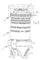
- the well illustrated with reference to the figures consists of a one-piece plastic housing made of plastic by rotational casting, which is formed by a lower housing section 1, a middle housing section 2 and an upper housing section 3.
- the lower housing section 1 forms the later pump sump of the well, the middle housing section 2 the well shaft and the upper housing section 3 a connection area for further below described components and an inspection opening 4, which is lockable by a cover 5.
- the well housing is essentially rotationally symmetrical about a longitudinal axis 6 which is approximately vertical in the installed position.
- the lower housing portion 1 has a cylindrical portion 7, which projects beyond the central housing portion 2 radially.
- the cylindrical portion 7 goes down into a tapered portion 8, which extends to the bottom 9 of the well housing.
- two support ribs 10 which are offset by 180 ° with respect to one another and are arranged on the axis 6 are provided, which are hollow and are formed integrally with the rest of the housing. These support ribs extend to the footprint of the well housing, stabilize the tapered portion 8 in the wall area and also form a particular support laterally to the bottom 9 to increase the footprint and thus the stability of the stand, especially when not yet installed.
- a bulge 11 is provided on one side and on the other side a receptacle 12, also in the form of a paragraph, as can be seen in particular from FIGS. 1 and 2 can be seen.
- Bulge 11 and receptacle 12 are arranged opposite one another and form, in particular Fig. 2 illustrates, also supports, which increase the footprint of the well housing.
- the bulge 11 is provided to have sufficient clearance for lowering the submersible pump unit 13 shown with reference to FIGS. 4 and 5, whereas the receptacle 12 is provided for fixing the lower end of a riser system 14, as can be seen in particular with reference to FIG ,
- the cylindrical section 7 In alignment with the receptacle 12, the cylindrical section 7 is retracted, such that a contact surface 15 extending essentially downwards therefrom of the middle housing section 2 is provided, which is provided on the inside of the well housing with a guide rail 16, which is also additionally or serves as an alternative to the lower attachment of the riser system 14.
- the lower housing section 1 is adjoined at the top by the middle housing section 2, which forms the later well shaft and is essentially cylindrical, but has a significantly smaller diameter than the cylindrical section 7 of the lower housing section 1 and thus springs back relative thereto.
- the middle housing portion 2 is formed ribbed in order to increase the stability.
- the here inwardly directed ribs 17 are formed by a meandering in cross-section housing wall However, they can also be reinforced if necessary by additional components, such as reinforcing rings and / or directed to the outside.
- the middle housing portion 2 goes up into the likewise cylindrical upper housing portion 1, which is, however, provided on its outer periphery with radially projecting rings 18, such that between two adjacent rings 18 each have a groove for receiving a circumferential rubber seal not shown here in detail is provided in the form of a sealing ring.
- These rubber seals serve to tightly connect a standardized concrete fountain ring 19, as shown by way of example in FIG. 7.
- the rings 18, as in particular also illustrated in FIG. 7, project radially relative to the middle housing section, such that the concrete fountain ring 19 is displaceable in the axial direction 6 of the well, that is to say also beyond the middle housing section 2.
- the upper housing portion 3 runs at its top to the inspection opening 4 toward, which is stepped, such that the cover 5 is optionally inserted sealingly in this, without the risk that this may fall into the well inside.
- the bolts themselves are rotatably mounted recessed from above, so that they are accessible and rotatable only with a special tool from the top of the lid ago.
- the clamping bolts 21 are pivoted into the clamping bolt receptacles 22 provided in this area in the upper housing section 3, whereby the cover 5 is braced against the housing section 3 and positively locked is locked.
- the inspection opening 4, which also forms the lid receptacle is designed so that instead of the plastic lid 5 and a standard metal / concrete lid can be used, as this also finds use in conventional wells.
- the entire well housing is typically up to the lid 5 below the surface or possibly even the lid itself.
- the top of the well is covered by a standard concrete fountain ring 19, which rests sealingly against the upper housing portion 3 , but otherwise freely movable in the direction of the longitudinal axis 6 of the well.
- the concrete fountain ring 19 is provided on its upper side with a lid, not shown, and known as such, which is why not described in detail here.
- a well known from the prior art riser system 14 is provided with which a submersible pump unit 13 can be discharged close to the bottom 9 of the well housing along the riser system 14 on a chain 23, which at the lower end automatically a fluid-conducting Making connection between the discharge nozzle of the pump assembly 13 and a riser pipe 24, which forms part of the riser system.
- the riser 24 is connected in parallel to a guide rail 25 fixedly connected thereto, on which the pump unit 13 is guided.
- the riser pipe 24 is bent at its upper end by 90 ° to a flange 26 which is provided for connection to an opposite flange 27 which is seated at the end of a pressure pipe 28, via which the pumped by the pump 13 liquid is discharged from the well ,
- the flanges 26 and 27 have, as can be seen with reference to FIG. 6, elongated holes 29 whose longitudinal axis is arranged parallel to the longitudinal axis 6 of the well.
- the line connections are also in this area formed slot-like, such that certain manufacturing tolerances in the direction of the axis 6 can be compensated, in which the flanges 26 and 27 not only aligned with each other, but to a certain extent in the direction of the axis 6 can be fixed to each other, without the To influence the functionality of the flange connection.
- the riser system 14 As shown with reference to FIG. 4, held with its lower end in the form provided in the lower housing section 1 receptacle 12, after this has been introduced from above into the receptacle 12. Secured to the top is the riser system 14 by a clamp 30 which connects the pressure tube 28 via a screw with the well housing.
- the riser system 14 may also be positively guided and fixed in the lower region on the guide rail 16 (FIG. 5), which is fastened to the contact surface 15 of the well housing, a securing against sliding upwards likewise takes place via the clamp fastening 30
- Both embodiments have the advantage that the entire riser system after loosening the flange connection, which can be done from above through the inspection opening 4, removed from the well and maintained or possibly replaced.
- a rod 31 is provided, to which various float switches 32 are attached, via which the pump control is activated and the level within the well can be determined.
- the rod 31 is fixed in the upper housing portion 3, so that these can be removed through the inspection opening 4 from above out.
Abstract
Description
Die Erfindung betrifft einen Brunnen mit den im Oberbegriff des Anspruchs 1 angegebenen Merkmalen.The invention relates to a well with the features specified in the preamble of
Derartige Brunnen werden typischerweise als Abwasserbrunnen eingesetzt, insbesondere dann, wenn Höhenunterschiede in der Abwasserleitung zu überwinden sind. Bei Erreichen einer vorbestimmten Füllstandshöhe springt die im Brunnen befindliche Tauchpumpe an und fördert das im Brunnen gesammelte Abwasser über eine Druckleitung vergleichsweise kleinen Querschnitts. Derartige Brunnen können auch zum Sammeln von Regenwasser oder andere Zwecke eingesetzt werden. Sie bestehen typischerweise aus einem Kunststoffgehäuse, das bei bekannten Brunnen im Wesentlichen zylindrisch ausgebildet ist. Dabei bildet ein unterer Abschnitt des Kunststoffgehäuses den späteren Brunnensumpf und der sich daran nach oben anschließende mittlere Gehäuseabschnitt den späteren Brunnenschacht, der nach oben hin meist durch einen Deckel abgeschlossen ist.Such wells are typically used as sewage wells, especially when height differences in the sewer pipe are to be overcome. Upon reaching a predetermined level height, the submersible pump located in the well and jumps the waste water collected in the well via a pressure line comparatively small cross-section. Such wells can also be used to collect rainwater or other purposes. They typically consist of a plastic housing, which is formed in known wells substantially cylindrical. In this case, a lower portion of the plastic housing forms the future well sump and the adjoining up the middle housing section the later well shaft, which is usually closed at the top by a cover.
Ein Nachteil bekannter Brunnen besteht darin, dass sie aufgrund ihrer im Wesentlichen zylindrischen Form am Boden vergleichsweise viel Wasser sammeln, was durch die Pumpe konstruktionsbedingt nicht abgesaugt werden kann. Weiterhin hat sich insbesondere in hochwassergefährdeten Gebieten gezeigt, dass solche Brunnen, wenn sie praktisch leer gepumpt sind, aufschwimmen können, wenn das umgebene Erdreich nur genügend aufgeweicht und mit Wasser angereichert ist.A disadvantage of wells known is that they collect comparatively much water due to their substantially cylindrical shape at the bottom, which can not be sucked by the pump design. Furthermore, it has been shown particularly in flood-prone areas that such wells, when they are pumped virtually empty, can float when the surrounding soil is sufficiently softened and enriched with water.
Vor diesem Hintergrund liegt der Erfindung die Aufgabe zugrunde, einen gattungsgemäßen Brunnen zu schaffen, der die vorgenannten Nachteile vermeidet.Against this background, the invention has for its object to provide a generic well, which avoids the aforementioned disadvantages.
Diese Aufgabe wird gemäß der Erfindung durch einen Brunnen mit den im Anspruch 1 angegebenen Merkmalen gelöst. Vorteilhafte Ausgestaltungen der Erfindungen sind in den Unteransprüchen, der nachfolgenden Beschreibung und der Zeichnung angegeben.This object is achieved according to the invention by a well having the features specified in
Der erfindungsgemäße Brunnen ist so ausgebildet, dass der untere Gehäuseabschnitt zum Boden hin verjüngend zulaufend ausgebildet ist, wobei der mittlere Gehäuseabschnitt gegenüber dem daran anschließenden Teil des unteren Gehäuseabschnitts nach innen zurückspringend ausgebildet ist. Diese Ausbildung hat den großen Vorteil, dass einerseits im Vergleich zum Brunnenschacht ein großes Volumen im unteren Gehäuseabschnitt gebildet ist, das jedoch aufgrund des nach unten zum Boden hin verjüngend zulaufenden Gehäuses nahezu vollständig abgepumpt werden kann. Das im Brunnen verbleibende Restvolumen ist deutlich kleiner als bei bekannten Ausführungen, da aufgrund der Gehäuseverjüngung nach unten hin der freie Brunnenquerschnitt und damit auch das dort befindliche nicht förderbare Restvolumen deutlich verkleinert ist.The well according to the invention is designed so that the lower housing portion is formed tapering towards the bottom, wherein the central housing portion is formed with respect to the adjoining part of the lower housing portion to spring back inside. This design has the great advantage that, on the one hand, in comparison to the well shaft, a large volume is formed in the lower housing section, which, however, can be almost completely pumped off due to the housing tapering towards the bottom. The residual volume remaining in the well is significantly smaller than in known designs, since due to the housing taper downwards, the free well cross-section and thus also the non-recoverable residual volume located there is significantly reduced.
Dadurch, dass der mittlere Gehäuseabschnitt, der den Brunnenschacht bildet, gegenüber dem daran anschließenden unteren Gehäuseabschnitt nach innen zurückspringt, kann der Materialeinsatz zur Herstellung des Brunnens bei vergleichbarer Stabilität deutlich verringert werden. Darüber hinaus ergibt sich durch den zurückspringenden Schacht der erhebliche Vorteil, dass der untere Gehäuseabschnitt von der Außenseite bis zu dem zurückspringenden mittleren Gehäuseabschnitt in eingebautem Zustand durch Erdreich überdeckt ist, und zwar über die gesamte Schachthöhe. Hierdurch wird zuverlässig ein Aufschwimmen des Brunnens verhindert, selbst wenn dieser leer ist und das umgebende Erdreich mit Wasser aufgeschwemmt ist.Due to the fact that the central housing section, which forms the well shaft, springs back inwards relative to the adjoining lower housing section, the material used to produce the well can be markedly reduced with comparable stability. In addition, resulting from the recessed shaft of the considerable advantage that the lower housing portion is covered by the outside to the recessed central housing portion in the installed state by soil, over the entire shaft height. This will reliably float prevents the well, even if it is empty and the surrounding soil is flooded with water.
Gemäß einer Weiterbildung der Erfindung schließt sich vorteilhaft an den mittleren Gehäuseabschnitt ein oberer Kunststoffgehäuseabschnitt an, der an seiner Oberseite eine Inspektionsöffnung aufweist, die mittels eines Deckels verschließbar ist. Über die Inspektionsöffnung ist der Brunnen zugänglich, über die Inspektionsöffnung sind auch sämtliche innerhalb des Brunnens angeordneten Aggregate, insbesondere die Tauchpumpe/Tauchpumpen und ggf. das damit verbundene Steigrohrsystem zugänglich.According to a development of the invention, an upper plastic housing section advantageously joins the middle housing section, which has an inspection opening on its upper side, which can be closed by means of a lid. The well is accessible via the inspection opening, and all the units arranged within the well, in particular the submersible pump / submersible pumps and possibly the riser system connected thereto, are accessible via the inspection opening.
Wie Eingangs erläutert, ist es aus mehreren Gründen zweckmäßig, die Gehäusewandung des unteren Gehäuseabschnitts zum Boden hin verjüngend auszubilden. Besonders vorteilhaft ist es dabei das Gehäuse in diesem verjüngenden Bereich in einem Winkel zur Gehäuselängsachse zwischen 30° und 60° in Einbaulage auszubilden.As explained at the beginning, it is expedient for a number of reasons to make the housing wall of the lower housing section tapering towards the bottom. It is particularly advantageous to form the housing in this tapered region at an angle to the housing longitudinal axis between 30 ° and 60 ° in the installed position.
Bevorzugt weist der obere Gehäuseabschnitt am Außenrand mindestens eine Aufnahme für ein Dichtmittel, z. B. in Form einer oder mehrerer Nuten zur Aufnahme einer oder mehrerer umlaufender Dichtringe auf, über die ein Verstärkungsring an der Außenseite des Brunnengehäuses dichtend anbindbar ist. Solche Verstärkungsringe aus Beton zählen zum Stand der Technik und sind genormt, weshalb es zweckmäßig ist, den oberen Gehäuseabschnitt so auszubilden, dass ein genormter Betonbrunnenring an der Außenseite des Brunnengehäuses dichtend anbindbar ist. Zweckmäßigerweise sind hier mehrere Dichtringe übereinander vorgesehen, damit auch bei Absacken des Betonbrunnenrings, wie dies beispielsweise durch Belastung oder Nachsacken des Erdreichs erfolgen kann, die dichtende Anlage am Brunnen gewährleistet ist. Dies ist deshalb wichtig, da solche genormten Betonbrunnenringe typischerweise einen eigenen Betonbrunnendeckel aufweisen, so dass, um zu verhindern, dass seitlich zwischen Brunnenring und Brunnen Wasser in den Brunnen ein- oder ausdringen kann, eine Abdichtung vorzusehen ist. Solche Betonbrunnenringe werden typischerweise dort eingesetzt, wo an der Oberseite des Brunnens erhöhte Belastungen eingebracht werden, beispielsweise im Fahrbahnbereich oder auf Plätzen, wo durch Fahrzeuge oder andere Gegenstände eine besonders hohe Belastung von oben zu erwarten ist.Preferably, the upper housing portion at the outer edge of at least one receptacle for a sealant, for. Example in the form of one or more grooves for receiving one or more circumferential sealing rings, via which a reinforcing ring on the outside of the well housing is sealingly attachable. Such reinforcing rings made of concrete are state of the art and are standardized, which is why it is expedient to form the upper housing section so that a standardized concrete fountain ring on the outside of the well housing is sealingly attachable. Conveniently, a plurality of sealing rings are provided one above the other, so that even when sagging the concrete fountain ring, as can be done for example by stress or Nachsacken the soil, the sealing contact is ensured at the well. This is important because such standardized concrete well rings typically have their own concrete fountain roof, so as to prevent water in between laterally between the well ring and the well the fountain can enter or exit, a seal is provided. Such concrete well rings are typically used where increased loads are introduced at the top of the well, for example in the carriageway area or on squares where a particularly high load from above is to be expected from vehicles or other objects.
Dabei ist es besonders vorteilhaft, wenn der obere Gehäuseabschnitt im Bereich der Dichtmittelaufnahme einen größeren Durchmesser als der den Schachtbereich bildenden mittlere Gehäuseabschnitt auf-weist. Nur dann ist nämlich sichergestellt, dass der Betonbrunnenring, der dichtend am oberen Gehäuseabschnitt anliegt, auch frei nach unten bewegbar ist, also ggf. absacken kann, ohne dass hierbei ungewollt Kräfte in die Brunnenstruktur, insbesondere das Kunststoffgehäuse eingeleitet werden.It is particularly advantageous if the upper housing portion in the region of the sealant receiving a larger diameter than the shaft portion forming the middle housing section has. Only then is it ensured that the concrete fountain ring, which bears sealingly against the upper housing section, is also freely movable downwards, that is to say may sag, without undesired forces being introduced into the well structure, in particular the plastic housing.
Gemäß einer Weiterbildung der Erfindung ist vorgesehen, dass der Brunnen, z. B. wenn er ohne Betonbrunnenring eingesetzt wird, einen eigenen, vorzugsweise aus Kunststoff gebildeten Deckel zum Verschließen der Inspektionsöffnung aufweist. Ein solcher Deckel kann ggf. auch zusätzlich unter dem Betondeckel des Betonbrunnenrings angeordnet sein oder einen genormten Betondeckel, der ebenfalls in der Inspektionsöffnung des Brunnens eingliederbar ist, ersetzen. Bei Betondeckeln ist der sichere Sitz üblicherweise durch Eigengewicht gewährleistet. Um dies auch bei einem vergleichsweise leichten Kunststoffdeckel zu erreichen, ist gemäß einer Weiterbildung der vorliegenden Erfindung vorgesehen, dass Spann- oder Verriegelungsmittel deckelseitig vorgesehen sind, welche den Deckel in der Inspektionsöffnung festlegen und die vorzugsweise so ausgebildet sind, dass sie von außen nur mittels eines Werkzeugs zugänglich sind, damit nicht unbefugte, insbesondere spielende Kinder den Deckel entfernen können.According to one embodiment of the invention, it is provided that the well, z. B. if it is used without concrete fountain ring, has its own, preferably formed from plastic lid for closing the inspection opening. If necessary, such a cover can also be arranged under the concrete cover of the concrete fountain ring or replace a standardized concrete cover, which can likewise be incorporated in the inspection opening of the fountain. For concrete lids, the secure fit is usually ensured by its own weight. In order to achieve this even with a comparatively lightweight plastic lid, it is provided according to a development of the present invention that clamping or locking means are provided on the lid side, which define the lid in the inspection opening and which are preferably designed so that they are only externally by means of a Tool are accessible so that not unauthorized, especially playing children can remove the lid.
Eine besonders hohe Stabilität bei vergleichsweise geringem Materialeinsatz erzielt man dann, wenn der Brunnen einen kreisrunden Querschnitt aufweist. Dabei ist insbesondere der mittlere Gehäuseabschnitt im Wesentlichen zylindrisch ausgebildet und weist umlaufende Versteifungsrippen auf, die entweder an der Gehäusewandung vorgesehen sind oder aber materialsparend bevorzugt derart, dass die Gehäusewandung selbst rippenförmig konturiert ist, um so bei vergleichsweise geringer Materialdicke eine hohe Eigenstabilität zu gewährleisten.A particularly high stability with comparatively low use of material is achieved when the well has a circular cross-section. In this case, in particular, the central housing portion is formed substantially cylindrical and has circumferential stiffening ribs, which are either provided on the housing or material saving preferably such that the housing itself is contoured rib-shaped, so as to ensure a high intrinsic stability with a comparatively small material thickness.
Die sich verjüngende Ausbildung des unteren Gehäuseabschnitts zum Boden hin hat zwar den Vorteil, dass das Restvolumen, das durch Abpumpen nicht entfernt werden kann, vergleichsweise gering bleibt, bedingt jedoch eine im Vergleich zu zylinderförmigen oder tonnenförmigen Brunnen eine kleinere Aufstandsfläche, was insbesondere in noch nicht eingebautem Zustand dazu führen kann, dass der Brunnen leicht umkippt. Um dies zu verhindern, ist gemäß der Erfindung vorgesehen, dass das Gehäuse mit Stützrippen versehen ist, welche sich von der schrägen Gehäusewandung nach unten zur Aufstandsebene des Brunnengehäuses erstrecken und so die Standstabilität des Brunnens erhöhen. Solche Stützrippen werden zweckmäßigerweise einstückig mit dem Brunnengehäuse ausgebildet und sind vorzugsweise als Hohlkörper ausgebildet, welche nicht mit dem Brunneninneren in Leitungsverbindung stehen. Dadurch wird einerseits verhindert, dass sich diese Stützrippen mit im Brunnen befindlicher Flüssigkeit füllen und andererseits, dass diese nicht aus Vollmaterial bestehen, was ungünstig wäre, da hierdurch einerseits ein hoher Materialaufwand bedingt wäre und zum anderen das Gewicht des Brunnens erhöht würde, was ebenfalls nicht erstrebenswert ist. Um die Hohlkörper auszubilden, ist im Bereich der Gehäusewandung eine Einschnürung vorgesehen, die bewirkt, dass sich beim Herstellen des Gehäuses im Rotationsgussverfahren eine geschlossene Innenwandung ausbildet. Alternativ kann die Einschnürung derart ausgebildet sein, dass die Stützrippen zwar hohl ausgebildet sind, aber mit Durchbrechungen zum Brunneninneren, so dass sich die Rippen mit Flüssigkeit füllen können, jedoch im Wesentlichen kein Flüssigkeitsaustausch zum Brunnen hin erfolgt.Although the tapered design of the lower housing portion towards the bottom has the advantage that the residual volume, which can not be removed by pumping, remains relatively low, but requires a compared to cylindrical or barrel-shaped wells a smaller footprint, which in particular not yet built-in condition can cause the well to tip over easily. To prevent this, it is provided according to the invention that the housing is provided with support ribs, which extend from the oblique housing wall down to the contact surface of the well housing and thus increase the stability of the well. Such support ribs are expediently formed integrally with the well housing and are preferably formed as a hollow body, which are not in line connection with the well interior. This prevents on the one hand, that fill these support ribs with befindlicher in the well liquid and on the other hand, that they are not made of solid material, which would be unfavorable, since this would on the one hand a high cost of materials would be required and on the other hand, the weight of the well would increase, which also not is desirable. In order to form the hollow body, a constriction is provided in the region of the housing wall, which causes a closed inner wall to be formed during the production of the housing in the rotational casting process. Alternatively, the constriction may be formed such that the support ribs are indeed hollow, but with openings to the well interior, so that the ribs can fill with liquid, but essentially no fluid exchange takes place to the well out.
Zweckmäßigerweise sind mehrere Stützrippen verteilt um die Gehäuseachse angeordnet, um Kippsicherheit in allen Richtungen zu gewährleisten. Bevorzugt sind zwei um 180° zur Gehäuselängsachse versetzt angeordnete Stützrippen vorgesehen, insbesondere wenn in den dazwischen liegenden Bereichen durch andere Ausgestaltungen des Gehäuses im Bodenbereich dafür Sorge getragen ist, dass eine entsprechende Stützwirkung auch in diesen Bereichen gegeben ist. Dies kann beispielsweise dadurch erreicht werden, dass im Bereich zwischen zwei Stützrippen eine Aufnahme für das untere Ende mindestens eines eine Tauchpumpe führenden Steigrohrsystems gebildet ist. Da das Steigrohrsystem so weit herunterreichen muss, dass die damit angeschlossene Tauchpumpe möglichst bodennah ansaugt, ist zweckmäßigerweise das Gehäuse in diesem Bereich so ausgebildet, dass ausreichend Raum für das senkrecht von oben längs der Brunnenwandung insbesondere der Schachtwandung angebrachte Steigrohrsystem verbleibt und eine entsprechende Aufnahme am unteren Ende vorgesehen ist. Diese Aufnahme kann auch zur Aufnahme von zwei Steigrohrsystemen vorgesehen sein, wenn zwei Pumpenaggregate vorgesehen sind.Conveniently, a plurality of support ribs distributed around the housing axis are arranged to ensure stability in all directions. Preferably, two staggered arranged by 180 ° to the housing longitudinal axis support ribs are provided, in particular if in the intervening areas by other embodiments of the housing in the bottom area care is taken that a corresponding support effect is given in these areas. This can be achieved, for example, by forming a receptacle for the lower end of at least one riser system leading to a submersible pump in the region between two support ribs. Since the riser system must extend so far that the submersible pump connected to it sucks as close to the ground as possible, the housing is expediently designed in this area so that sufficient space remains for the riser system mounted vertically from above along the well wall, in particular the shaft wall, and a corresponding receptacle at the bottom End is provided. This receptacle can also be provided for receiving two riser systems, if two pump units are provided.
Die Aufnahme ist dabei vorteilhaft so ausgebildet, dass das untere Ende des Steigrohrsystems von oben in diese derart eingliederbar ist, dass Formschluss quer zur Längsachse des Gehäuses nach Einsetzen gebildet ist, also das Steigrohrsystem mit dem unteren Ende im Gehäuse festgelegt ist.The receptacle is advantageously designed so that the lower end of the riser system can be inserted from above into it in such a way that positive engagement is formed transversely to the longitudinal axis of the housing after insertion, ie the riser system is fixed with the lower end in the housing.
Auf der gegenüberliegenden Seite, also ebenfalls zwischen zwei um 180° versetzt zueinander angeordneten Stützrippen weist das Gehäuse vorteilhaft gegenüberliegend zur Aufnahme eine Ausbauchung auf, welche sich bis zum Boden des Gehäuses erstreckt. Diese Ausbauchung erhöht ebenfalls die Standfestigkeit zu dieser Seite des Gehäuses und gibt den erforderlichen Freiraum für den in der Regel großflächigen bodenseitigen Saugmund der Pumpe bzw. der Pumpen, wenn mehrere vorgesehen sind. Die Ausbauchung ist zweckmäßigerweise an die Außenkontur der Pumpe in diesem Bereich angepasst.On the opposite side, so also between two offset by 180 ° to each other arranged support ribs, the housing advantageously opposite to the receiving a bulge, which extends to the bottom of the housing. This bulge also increases the stability to this side of the housing and gives the necessary space for the generally large-scale bottom suction port of the pump or pumps, if several are provided. The bulge is suitably adapted to the outer contour of the pump in this area.
Das Steigrohrsystem kann in dem Brunnen gemäß der Erfindung vorteilhaft in der bodenseitigen Aufnahme des Gehäuses durch einfaches Einstecken von oben festgelegt sein. Alternativ oder zusätzlich kann im unteren Gehäuseabschnitt eine Führung für das Steigrohrsystem vorgesehen sein, welche vorzugsweise eine am Gehäuse befestigte Führungsschiene aufweist, an welche das Steigrohrsystem nur in Richtung zur Gehäuselängsachse bewegbar ist. Eine solche Führungsschiene besteht vorteilhaft aus Edelstahl, kann jedoch auch aus anderen Materialien gebildet sein. Sowohl die bodenseitige Aufnahme als auch die Führungsschiene ermöglichen in vorteilhafter Weise, nicht nur die Pumpe am Steigrohrsystem zuziehen, wie dies zum Stand der Technik zählt, sondern darüber hinaus das gesamte Steigrohrsystem von oben aus dem Brunnen zu entfernen, um dies ggf. zu reparieren oder auszutauschen.The riser system can be advantageously determined in the well according to the invention in the bottom-side receptacle of the housing by simply plugging in from above. Alternatively or additionally, a guide for the riser system may be provided in the lower housing portion, which preferably has a guide rail attached to the housing, to which the riser system is movable only in the direction of the housing longitudinal axis. Such a guide rail is advantageously made of stainless steel, but may also be formed of other materials. Both the bottom-side receptacle and the guide rail advantageously make it possible not only to pull the pump on the riser system, as is state-of-the-art, but also to remove the entire riser system from above the well in order to repair it if necessary or exchange.
Um der Führungsschiene eine möglichst lange und vollflächige Anlage und damit eine stabile Befestigung zu gewährleisten, ist es vorteilhaft, im Bereich der Führungsschiene, also insbesondere im Bereich des unteren Gehäuseabschnitts diesen eingezogen auszubilden derart, dass die Führungsschiene über im Wesentlichen die ganze Höhe des unteren Gehäuseabschnitts flächig durch den eingezogenen Bereich der Gehäusewandung abgestützt ist. Da der eingezogene Bereich gegenüber dem übrigen Gehäuse zurückfällt, ist dieser durch die sich notwendigerweise ergebenden und etwa radial verlaufenden Wandabschnitte zusätzlich versteift und in diesem Bereich besonders formstabil.In order to ensure that the guide rail is as long and full-surface contact as possible and thus stable, it is advantageous to design it retracted in the region of the guide rail, in particular in the area of the lower housing section such that the guide rail extends over substantially the entire height of the lower housing section is supported flat by the retracted area of the housing. Since the retracted area falls back relative to the rest of the housing, this is additionally stiffened by the necessarily resulting and approximately radially extending wall sections and particularly dimensionally stable in this area.
Zweckmäßigerweise ist das Steigrohrsystem an zwei Stellen, bevorzugt nahe dem unteren und dem oberen Ende brunnenseitig festgelegt, um eine stabile Anbindung an das Brunnengehäuse sicherzustellen. Bodenseitig erfolgt dies durch die Aufnahme und/oder die im unteren Gehäuseabschnitt angeordnete Führungsschiene. Beide Systeme sind so ausgelegt, dass ein Austausch ohne unmittelbaren Zugang zum Brunnen, sondern nur durch die Inspektionsöffnung an der Oberseite erfolgen kann. Um dies auch im oberen Bereich sicherzustellen, insbesondere die Leitungsverbindung zwischen dem Steigrohrsystem und dem eigentlichen Druckrohr, welche die abführende Leitungsverbindung aus dem Brunnen nach außen bildet, sicherzustellen, ist deshalb nahe dem oberen Brunnenende innerhalb des Brunnens eine Flanschverbindung vorgesehen, die so angeordnet ist, dass sie von der Inspektionsöffnung her zugänglich ist.Conveniently, the riser system at two points, preferably near the bottom and the upper end of the fountain side set to to ensure a stable connection to the well housing. On the bottom side, this is done by the recording and / or arranged in the lower housing section guide rail. Both systems are designed so that replacement without direct access to the well, but only through the inspection opening at the top can be done. In order to ensure this in the upper area, in particular to ensure the line connection between the riser system and the actual pressure tube, which forms the laxative line connection from the well to the outside, therefore, a flange connection is provided near the upper end of the well, which is arranged so that it is accessible from the inspection opening.
Um eine höhenmäßige Anpassung zwischen dem brunnenseitigen Druckrohr einerseits und dem Steigrohr andererseits zu ermöglichen ist gemäß einer Weiterbildung der Erfindung die Flanschverbindung mit Langlöchern versehen, die so angeordnet sind, dass deren lange Achse parallel zur Längsachse des Gehäuses angeordnet ist, d. h. dass die Flansche mit einem gewissen Höhenspiel zueinander verschraubt werden können, ohne dass dies Einwirkungen auf die dadurch gebildete Leitungsverbindung oder die Festigkeit der Flanschverbindung hat. Entsprechend sind die Leitungsmündungen in den Flanschen langlochartig ausgebildet. Vorzugsweise sind die Flansche mit den darin mündenden bogenförmigen Rohrabschnitten jeweils einstückig als Gussteile aus vorzugsweise Edelstahl hergestellt.In order to allow a height adjustment between the well-side pressure tube on the one hand and the riser pipe on the other hand, according to an embodiment of the invention, the flange provided with slots which are arranged so that their long axis is arranged parallel to the longitudinal axis of the housing, d. H. that the flanges can be bolted to each other with a certain height clearance, without this having any effect on the thus formed line connection or the strength of the flange connection. Accordingly, the pipe mouths are formed slot-like in the flanges. Preferably, the flanges with the arcuate tubular sections opening into them are each produced in one piece as castings of preferably stainless steel.
Zweckmäßigerweise wird das obere Ende des Steigrohrsystems über die Flanschverbindung zum Druckrohr befestigt, welches im Bereich zwischen der Gehäusedurchführung und dem Flansch am Gehäuse lösbar befestigt ist, vorzugsweise schraubbefestigt ist. Dabei ist im Bereich der Befestigung das Gehäuse verstärkt, um eine stabile und verbindungssteife Anbindung an das Gehäuse sicherzustellen. Auch diese Befestigungsstelle im Gehäuse ist so angeordnet, dass sie nach Möglichkeit durch die Inspektionsöffnung von oben zugänglich ist, so dass sämtliche innerhalb des Brunnens befindliche Bauteile durch die Inspektionsöffnung ausgetauscht werden können, ohne in den Brunnen steigen zu müssen.Conveniently, the upper end of the riser system is attached via the flange to the pressure tube, which is releasably secured in the region between the housing passage and the flange on the housing, preferably screw-mounted. In this case, the housing is reinforced in the attachment, to ensure a stable and rigid connection to the housing. Also, this attachment point in the housing is arranged so that they possible through the inspection opening is accessible from above, so that all located within the well components can be replaced through the inspection opening without having to get into the well.
Besonders vorteilhaft ist es, wenn das Brunnengehäuse zumindest innenseitig eine helle Farbe aufweist, zweckmäßigerweise der das Gehäuse bildende Kunststoff von heller Farbe ist, so dass schon ein geringer Lichteinfall genügt, um eine Inaugenscheinnahme des Brunneninneren zu ermöglichen. Insbesondere die bekannten aus Kunststoff gebildeten Brunnengehäuse sind typischerweise dunkel, was von erheblichen Nachteil ist, da nur über intensive zusätzliche Beleuchtung das Brunneninnere durch Inaugenscheinnahme inspizierbar ist.It is particularly advantageous if the well housing at least on the inside has a light color, expediently the plastic forming the housing is of light color, so that even a low incidence of light is sufficient to allow an inspection of the inside of the well. In particular, the well-known plastic housing wells are typically dark, which is a considerable disadvantage, since the well inside can be inspected by visual inspection only through intensive additional lighting.
Das erfindungsgemäße Brunnengehäuse ist vorteilhaft einstückig ausgebildet und durch Rotationsguss aus Kunststoff hergestellt.The well housing according to the invention is advantageously formed in one piece and produced by rotational molding of plastic.
Die Erfindung ist nachfolgend anhand eines in der Zeichnung dargestellten Ausführungsbeispiels erläutert. Es zeigen:
- Fig. 1
- ein erfindungsgemäßes Brunnengehäuse in perspektivischer Seitenansicht mit abgehobenem Deckel,
- Fig. 2
- eine perspektivische Ansicht des Brunnengehäuses gemäß Fig. 1 von der Unterseite,
- Fig. 3
- einen Schnitt längs der Schnittebene III in Fig. 2,
- Fig. 4
- eine perspektivische Längsschnittdarstellung durch den fertigen Brunnen,
- Fig. 5
- eine alternative Ausführungsvariante in Darstellung nach Fig. 4,
- Fig. 6
- in perspektivischer vergrößerter Explosionsdarstellung die Flanschverbindung zwischen Steigrohrsystem und Druckrohr und
- Fig. 7
- ein Brunnengehäuse mit aufgesetztem genormten Betonbrunnenring in Darstellung nach Fig. 1.
- Fig. 1
- an inventive well housing in a perspective side view with lifted lid,
- Fig. 2
- 1 is a perspective view of the well housing according to FIG. 1 from the underside, FIG.
- Fig. 3
- a section along the sectional plane III in Fig. 2,
- Fig. 4
- a perspective longitudinal section through the finished well,
- Fig. 5
- an alternative embodiment in representation of FIG. 4,
- Fig. 6
- in an enlarged perspective exploded view of the flange connection between riser system and pressure tube and
- Fig. 7
- a well housing with attached standardized concrete fountain ring in the representation of FIG. 1.
Der anhand der Figuren dargestellte Brunnen besteht aus einem einstückigen, im Rotationsgussverfahren hergestellten Brunnengehäuse aus Kunststoff, welches durch einen unteren Gehäuseabschnitt 1, einen mittleren Gehäuseabschnitt 2 und einen oberen Gehäuseabschnitt 3 gebildet ist. Der untere Gehäuseabschnitt 1 bildet den späteren Pumpensumpf des Brunnens, der mittlere Gehäuseabschnitt 2 den Brunnenschacht und der obere Gehäuseabschnitt 3 einen Anschlussbereich für weiter unten noch im Einzelnen beschriebene Bauteile sowie eine Inspektionsöffnung 4, welche durch einen Deckel 5 abschließbar ist. Das Brunnengehäuse ist im Wesentlichen rotationsymmetrisch um eine in Einbaulage etwa senkrechte Längsachse 6 ausgebildet.The well illustrated with reference to the figures consists of a one-piece plastic housing made of plastic by rotational casting, which is formed by a
Der untere Gehäuseabschnitt 1 weist einen zylindrischen Abschnitt 7 auf, der den mittleren Gehäuseabschnitt 2 radial deutlich überragt. Der zylindrische Abschnitt 7 geht nach unten hin in einen konisch zulaufenden Abschnitt 8 über, der bis zum Boden 9 des Brunnengehäuses reicht. Im Bereich des konisch zulaufenden Abschnitts 8 sind zwei um 180° zueinander bezogen auf die Achse 6 versetzt angeordnete Stützrippen 10 vorgesehen, welche hohl sind und einstückig mit dem übrigen Gehäuse ausgebildet sind. Diese Stützrippen reichen bis zur Aufstandsfläche des Brunnengehäuses, stabilisieren den konisch zulaufenden Abschnitt 8 im Wandbereich und bilden darüber hinaus insbesondere eine Stütze seitlich zum Boden 9, um die Aufstandsfläche und damit die Standstabilität insbesondere bei noch nicht eingebautem Zustand zu erhöhen. Um die Stützrippen 10 als geschlossenen Hohlkörper auszubilden, sind nahe der Gehäusewandung eingeschnürte Bereiche 33 vorgesehen, welche sich beim Rotationsgussverfahren derart zusetzen, dass ein weiterer Materialfluss in den Stützfußbereich unterdrückt wird und eine geschlossene Brunneninnenwandung entsteht.The
Zwischen den Stützrippen 10, also jeweils um 90° zu einer Stützrippe 10 bezogen auf die Längsachse versetzt, ist zu einer Seite eine Ausbauchung 11 vorgesehen und zur anderen Seite eine Aufnahme 12, ebenfalls in Form eines Absatzes, wie sich dies insbesondere aus den Fig. 1 und 2 entnehmen lässt. Ausbauchung 11 und Aufnahme 12 sind gegenüberliegend angeordnet und bilden, wie insbesondere Fig. 2 verdeutlicht, ebenfalls Stützen, welche die Aufstandsfläche des Brunnengehäuses vergrößern. Die Ausbauchung 11 ist vorgesehen, um ausreichend Freiraum zum Absenken des anhand der Fig. 4 und 5 dargestellten Tauchpumpenaggregats 13 zu haben, wohingegen die Aufnahme 12 zur Festlegung des unteren Endes eines Steigrohrsystems 14 vorgesehen ist, wie dies insbesondere anhand von Fig. 4 ersichtlich ist.Between the
Fluchtend zur Aufnahme 12 ist der zylindrische Abschnitt 7 eingezogen ausgebildet, derart, dass sich dort eine im Wesentlichen die Wandung des mittleren Gehäuseabschnittes 2 nach unten fortsetzende Anlagefläche 15 ergibt, die an der Innenseite des Brunnengehäuses mit einer Führungsschiene 16 versehen ist, die ebenfalls zusätzlich oder alternativ zur unteren Befestigung des Steigrohrsystems 14 dient.In alignment with the
An den unteren Gehäuseabschnitt 1 schließt sich nach oben der mittlere Gehäuseabschnitt 2 an, welcher den späteren Brunnenschacht bildet und im Wesentlichen zylindrisch ausgebildet ist, jedoch einen deutlich kleineren Durchmesser als der zylindrische Abschnitt 7 des unteren Gehäuseabschnitt 1 aufweist und somit gegenüber diesem zurückspringt. Der mittlere Gehäuseabschnitt 2 ist berippt ausgebildet, um die Stabilität zu erhöhen. Die hier nach innen gerichteten Rippen 17 sind durch eine im Querschnitt mäanderförmig verlaufende Gehäusewandung gebildet, also durch entsprechende Ausformung des Gehäuses selbst. Sie können jedoch auch ggf. durch zusätzliche Bauteile, beispielsweise Armierungsringe verstärkt sein und/oder nach außen gerichtet.The
Der mittlere Gehäuseabschnitt 2 geht nach oben in den ebenfalls zylindrischen oberen Gehäuseabschnitt 1 über, der jedoch an seinem Außenumfang mit radial vorspringenden Ringen 18 versehen ist, derart, dass zwischen zwei benachbarten Ringen 18 jeweils eine Nut zur Aufnahme einer hier nicht im Einzelnen dargestellten umlaufenden Gummidichtung in Form eines Dichtrings vorgesehen ist. Diese Gummidichtungen dienen zum dichten Anschluss eines genormten Betonbrunnenrings 19, wie dieser beispielhaft in Fig. 7 dargestellt ist. Die Ringe 18 springen, wie insbesondere auch die Fig. 7 verdeutlicht, gegenüber dem mittleren Gehäuseabschnitt radial vor, derart, dass der Betonbrunnenring 19 in Achsrichtung 6 des Brunnens verschiebbar ist, also auch bis über den mittleren Gehäuseabschnitt 2.The
Der obere Gehäuseabschnitt 3 läuft an seiner Oberseite zur Inspektionsöffnung 4 hin zu, welche stufenförmig ausgebildet ist, derart, dass der Deckel 5 in diese ggf. dichtend einlegbar ist, ohne dass die Gefahr besteht, dass dieser ins Brunneninnere hineinfallen kann.The
Der in den Fig. dargestellte Deckel 5 besteht aus Kunststoff und weist drei drehbar im Deckel gelagerte Bolzen 20 auf, welche an ihrem unteren Ende mit einem sich quer zur Bolzenachse erstreckenden Spannriegel 21 versehen sind, die drehfest mit den Bolzen 20 verbunden sind. Die Bolzen selbst sind von oben gesehen versenkt drehbar gelagert, so dass sie nur mit einem Spezialwerkzeug von der Oberseite des Deckels her zugänglich und drehbar sind. Durch Drehen der Bolzen 20 werden die Spannriegel 21 in die in diesem Bereich im oberen Gehäuseabschnitt 3 vorgesehenen Spannriegelaufnahmen 22 geschwenkt, wodurch der Deckel 5 gegenüber dem Gehäuseabschnitt 3 verspannt und formschlüssig verriegelt wird. Die Inspektionsöffnung 4, die zugleich die Deckelaufnahme bildet, ist so gestaltet, dass anstelle des Kunststoffdeckels 5 auch ein genormter Metall-/Betondeckel eingesetzt werden kann, wie dieser auch bei herkömmlichen Brunnen Verwendung findet.The
In Einbaulage befindet sich das gesamte Brunnengehäuse typischerweise bis zum Deckel 5 unter der Erdoberfläche oder ggf. auch der Deckel selbst. Bei der Ausführungsvariante nach Fig. 7 ist die Oberseite des Brunnens durch einen genormten Betonbrunnenring 19 überdeckt, der dichtend an dem oberen Gehäuseabschnitt 3 anliegt, jedoch im Übrigen in Richtung der Längsachse 6 des Brunnens frei bewegbar ist. Der Betonbrunnenring 19 ist an seiner Oberseite mit einem nicht dargestellten Deckel versehen und als solcher bekannt, weshalb hier auch nicht im Einzelnen beschrieben.In installation position, the entire well housing is typically up to the
Innerhalb des Brunnengehäuses ist ein an sich ebenfalls aus dem Stand der Technik bekanntes Steigrohrsystem 14 vorgesehen, mit welchem ein Tauchpumpenaggregat 13 bis nahe zum Boden 9 des Brunnengehäuses längs des Steigrohrsystems 14 an einer Kette 23 abgelassen werden kann, das an dem unteren Endpunkt selbsttätig eine fluidleitende Verbindung zwischen dem Druckstutzen des Pumpenaggregats 13 und einem Steigrohr 24 herstellt, das Teil des Steigrohrsystems bildet. Das Steigrohr 24 ist parallel zu einer fest damit verbundenen Führungsschiene 25 verbunden, an der das Pumpenaggregat 13 geführt ist. Das Steigrohr 24 ist an seinem oberen Ende um 90° abgekröpft zu einem Flansch 26, der zum Anschluss an einen gegenüberliegenden Flansch 27 vorgesehen ist, der am Ende eines Druckrohres 28 sitzt, über welches die von der Pumpe 13 geförderte Flüssigkeit aus dem Brunnen abgeleitet wird.Within the well housing, a well known from the prior
Die Flansche 26 und 27 haben, wie anhand von Fig. 6 ersichtlich ist, Langlöcher 29, deren Längsachse parallel zur Längsachse 6 des Brunnens angeordnet ist. Darüber hinaus sind auch die Leitungsanschlüsse in diesem Bereich langlochartig ausgebildet, derart, dass gewisse Fertigungstoleranzen in Richtung der Achse 6 ausgeglichen werden können, in dem die Flansche 26 und 27 nicht nur fluchtend zueinander, sondern in einem gewissen Maße auch in Richtung der Achse 6 versetzt zueinander befestigt werden können, ohne die Funktionalität der Flanschverbindung zu beeinflussen.The
Bei dem beschriebenen Brunnen ist nicht nur das Pumpenaggregat 13 austauschbar, sondern das gesamte Steigrohrsystem 14 sowie auch die übrigen im Brunnen befindlichen Aggregatteile. Hierzu ist das Steigrohrsystem 14, wie anhand Fig. 4 dargestellt, mit seinem unteren Ende in der im unteren Gehäuseabschnitt 1 vorgesehenen Aufnahme 12 formschlüssig gehalten, nachdem dieses von oben in die Aufnahme 12 eingeführt worden ist. Nach oben hin gesichert ist das Steigrohrsystem 14 durch eine Schelle 30, welche das Druckrohr 28 über eine Schraubverbindung mit dem Brunnengehäuse fest verbindet.In the well described not only the
Alternativ oder zusätzlich kann das Steigrohrsystem 14 auch im unteren Bereich an der Führungsschiene 16 (Fig. 5), welche an der Anlagefläche 15 des Brunnengehäuses befestigt ist, formschlüssig geführt und festgelegt sein, eine Sicherung gegen Herausgleiten nach oben erfolgt dort ebenfalls über die Schellenbefestigung 30 des Druckrohrs 28. Beide Ausbildungen haben den Vorteil, dass das gesamte Steigrohrsystem nach Lösen der Flanschverbindung, was von oben durch die Inspektionsöffnung 4 erfolgen kann, aus dem Brunnen entnommen und gewartet oder ggf. ausgetauscht werden kann.Alternatively or additionally, the
Weiterhin ist innerhalb des Brunnens noch eine Stange 31 vorgesehen, an welcher diverse Schwimmerschalter 32 befestigt sind, über die die Pumpensteuerung aktiviert wird und der Füllstand innerhalb des Brunnens ermittelbar ist. Die Stange 31 ist im oberen Gehäuseabschnitt 3 befestigt, so dass auch diese durch die Inspektionsöffnung 4 von oben heraus entfernt werden kann.Furthermore, within the well still a rod 31 is provided, to which various float switches 32 are attached, via which the pump control is activated and the level within the well can be determined. The rod 31 is fixed in the
- 11
- unterer Gehäuseabschnittlower housing section
- 22
- mittlerer Gehäuseabschnittmiddle housing section
- 33
- oberer GehäuseabschnittUpper housing section
- 44
- Inspektionsöffnunginspection opening
- 55
- Deckelcover
- 66
- Längsachse des BrunnensLongitudinal axis of the fountain
- 77
- zylindrischer Abschnitt des unteren Gehäuseabschnittscylindrical portion of the lower housing portion
- 88th
- konisch zulaufender Abschnitt des unteren Gehäuseabschnittstapered portion of the lower housing portion
- 99
- Boden des unteren GehäuseabschnittsBottom of the lower housing section
- 1010
- Stützrippen des unteren GehäuseabschnittsSupport ribs of the lower housing section
- 1111
- Ausbauchung des unteren GehäuseabschnittsBulging of the lower housing section
- 1212
- Aufnahme des unteren GehäuseabschnittsPicture of the lower housing section
- 1313
- TauchpumpenaggregatA submersible pump unit
- 1414
- SteigrohrsystemRiser system
- 1515
- Anlageflächecontact surface
- 1616
- Führungsschieneguide rail
- 1717
- Rippen des mittleren GehäuseabschnittsRipping the middle housing section
- 1818
- Ringe des oberen GehäuseabschnittsRings of the upper housing section
- 1919
- BetonbrunnenringConcrete fountain ring
- 2020
- Bolzenbolt
- 2121
- Spannriegelclamping bolts
- 2222
- SpannriegelaufnahmenClamping locking recesses
- 2323
- KetteChain
- 2424
- Steigrohrriser
- 2525
- Führungsschieneguide rail
- 2626
- Flanschflange
- 2727
- Flanschflange
- 2828
- Druckrohrpressure pipe
- 2929
- Langlöcherslots
- 3030
- Schelleclamp
- 3131
- Stangepole
- 3232
- Schwimmerschalterfloat switch
- 3333
- Einschnürungconstriction
Claims (20)
Priority Applications (4)
| Application Number | Priority Date | Filing Date | Title |
|---|---|---|---|
| DE502004007849T DE502004007849D1 (en) | 2004-09-24 | 2004-09-24 | Fountain |
| EP04022867A EP1640510B1 (en) | 2004-09-24 | 2004-09-24 | Well |
| PL04022867T PL1640510T3 (en) | 2004-09-24 | 2004-09-24 | Well |
| AT04022867T ATE404741T1 (en) | 2004-09-24 | 2004-09-24 | SPRING |
Applications Claiming Priority (1)
| Application Number | Priority Date | Filing Date | Title |
|---|---|---|---|
| EP04022867A EP1640510B1 (en) | 2004-09-24 | 2004-09-24 | Well |
Publications (2)
| Publication Number | Publication Date |
|---|---|
| EP1640510A1 true EP1640510A1 (en) | 2006-03-29 |
| EP1640510B1 EP1640510B1 (en) | 2008-08-13 |
Family
ID=34926713
Family Applications (1)
| Application Number | Title | Priority Date | Filing Date |
|---|---|---|---|
| EP04022867A Active EP1640510B1 (en) | 2004-09-24 | 2004-09-24 | Well |
Country Status (4)
| Country | Link |
|---|---|
| EP (1) | EP1640510B1 (en) |
| AT (1) | ATE404741T1 (en) |
| DE (1) | DE502004007849D1 (en) |
| PL (1) | PL1640510T3 (en) |
Cited By (8)
| Publication number | Priority date | Publication date | Assignee | Title |
|---|---|---|---|---|
| WO2010077157A1 (en) * | 2008-12-30 | 2010-07-08 | Inwap Sp. Z.O.O. | A tank for a sewage pumping station |
| EP2221422A1 (en) * | 2009-02-21 | 2010-08-25 | Grundfos Management A/S | Collection container for waste water hoisting facility |
| EP2447190A1 (en) * | 2010-10-26 | 2012-05-02 | Wisy AG | Underground tank made of plastic |
| WO2017114486A1 (en) * | 2015-12-31 | 2017-07-06 | 格兰富控股联合股份公司 | Prefabricated pump station unit and water distribution unit |
| CN106930398A (en) * | 2015-12-31 | 2017-07-07 | 格兰富控股联合股份公司 | Prefabricated pumping plant unit and water dispensing unit |
| RU2736679C1 (en) * | 2020-05-28 | 2020-11-19 | Александр Иванович Худолий | Observation well of underground communications |
| CN112012330A (en) * | 2020-09-07 | 2020-12-01 | 中国十七冶集团有限公司 | Installation and construction method of integrated sewage lifting equipment under roadway |
| EP4327910A1 (en) * | 2022-08-25 | 2024-02-28 | AGU Arbeitsgemeinschaft Umwelt GmbH | Device for operating a water game |
Citations (6)
| Publication number | Priority date | Publication date | Assignee | Title |
|---|---|---|---|---|
| FR1544054A (en) * | 1966-08-23 | 1968-10-31 | Stenberg Flygt Ab | Group of construction elements, in particular for wells, interlocking and method of application thereof |
| US4472911A (en) * | 1981-02-13 | 1984-09-25 | Pont-A-Mousson S.A. | Construction for access to a buried pipeline |
| GB2145444A (en) * | 1983-08-05 | 1985-03-27 | John Patrick Telford | Manhole chambers |
| DE4315535A1 (en) * | 1993-05-10 | 1994-11-17 | Kordes Klaeranlagen U Pumpwerk | Plastic shaft |
| US5727901A (en) * | 1996-01-18 | 1998-03-17 | Rennie; David G. | Collection tank |
| GB2374379A (en) * | 2001-03-20 | 2002-10-16 | Shaun Hume | Domestic water tank |
-
2004
- 2004-09-24 EP EP04022867A patent/EP1640510B1/en active Active
- 2004-09-24 AT AT04022867T patent/ATE404741T1/en not_active IP Right Cessation
- 2004-09-24 DE DE502004007849T patent/DE502004007849D1/en active Active
- 2004-09-24 PL PL04022867T patent/PL1640510T3/en unknown
Patent Citations (6)
| Publication number | Priority date | Publication date | Assignee | Title |
|---|---|---|---|---|
| FR1544054A (en) * | 1966-08-23 | 1968-10-31 | Stenberg Flygt Ab | Group of construction elements, in particular for wells, interlocking and method of application thereof |
| US4472911A (en) * | 1981-02-13 | 1984-09-25 | Pont-A-Mousson S.A. | Construction for access to a buried pipeline |
| GB2145444A (en) * | 1983-08-05 | 1985-03-27 | John Patrick Telford | Manhole chambers |
| DE4315535A1 (en) * | 1993-05-10 | 1994-11-17 | Kordes Klaeranlagen U Pumpwerk | Plastic shaft |
| US5727901A (en) * | 1996-01-18 | 1998-03-17 | Rennie; David G. | Collection tank |
| GB2374379A (en) * | 2001-03-20 | 2002-10-16 | Shaun Hume | Domestic water tank |
Cited By (9)
| Publication number | Priority date | Publication date | Assignee | Title |
|---|---|---|---|---|
| WO2010077157A1 (en) * | 2008-12-30 | 2010-07-08 | Inwap Sp. Z.O.O. | A tank for a sewage pumping station |
| EP2221422A1 (en) * | 2009-02-21 | 2010-08-25 | Grundfos Management A/S | Collection container for waste water hoisting facility |
| EP2447190A1 (en) * | 2010-10-26 | 2012-05-02 | Wisy AG | Underground tank made of plastic |
| WO2017114486A1 (en) * | 2015-12-31 | 2017-07-06 | 格兰富控股联合股份公司 | Prefabricated pump station unit and water distribution unit |
| CN106930398A (en) * | 2015-12-31 | 2017-07-07 | 格兰富控股联合股份公司 | Prefabricated pumping plant unit and water dispensing unit |
| RU2736679C1 (en) * | 2020-05-28 | 2020-11-19 | Александр Иванович Худолий | Observation well of underground communications |
| CN112012330A (en) * | 2020-09-07 | 2020-12-01 | 中国十七冶集团有限公司 | Installation and construction method of integrated sewage lifting equipment under roadway |
| EP4327910A1 (en) * | 2022-08-25 | 2024-02-28 | AGU Arbeitsgemeinschaft Umwelt GmbH | Device for operating a water game |
| DE102022121596A1 (en) | 2022-08-25 | 2024-03-07 | AGU Arbeitsgemeinschaft Umwelt GmbH | Device for operating a water feature |
Also Published As
| Publication number | Publication date |
|---|---|
| PL1640510T3 (en) | 2009-01-30 |
| ATE404741T1 (en) | 2008-08-15 |
| EP1640510B1 (en) | 2008-08-13 |
| DE502004007849D1 (en) | 2008-09-25 |
Similar Documents
| Publication | Publication Date | Title |
|---|---|---|
| DE2701157A1 (en) | Odor trap for liquids | |
| EP2230359A2 (en) | Construction set for a connection of an inspection shaft with a drainage line | |
| EP1640510B1 (en) | Well | |
| WO2018104411A2 (en) | Pressure-flushing system for a toilet bowl | |
| EP2508686B1 (en) | Retention assembly for precipitation and waste water | |
| DE202005021846U1 (en) | Manhole frame with receptacle for boarding assistance | |
| DE3333883C2 (en) | ||
| EP3058145B1 (en) | Sewage pumping station | |
| DE602004007445T2 (en) | floor drain | |
| CH692789A5 (en) | Floating baffle. | |
| DE202004017607U1 (en) | Insert part and drainage system | |
| DE202006003408U1 (en) | Shaft covering with casted socket as access help e.g. for covering shaft for surface water drainage, has framework made from cast material and placeable on shaft with cover provided for locking shaft with framework | |
| DE19882781B4 (en) | Flush valve piecing | |
| DE3335435A1 (en) | Tank for a sewage pumping station | |
| DE102007020399B4 (en) | Tank, especially underground tank | |
| DE10052324A1 (en) | Underground tank, in particular, for storing rainwater or waste water takes the form of a tubular body which is located on a substantially horizontal plane and surrounds an interior area | |
| DE3044426C2 (en) | ||
| DE10204683B4 (en) | pool | |
| EP1942276A2 (en) | Material feed receptacle for a thick matter pump | |
| DE102004053056B3 (en) | Two-part waste water collection shaft assembled from two truncated cones joined by bolted flanges | |
| DE10337127B4 (en) | Post for insertion into a subsoil or subsoil | |
| DE19610858C2 (en) | Trash box | |
| DE19932859C2 (en) | Aseptic pump housing with switchable drainage | |
| EP4001655B1 (en) | Submersible pressure pump for liquid and use thereof | |
| DE19546102C2 (en) | Arrangement for preventing the entry of vermin from a downpipe into toilet bowls |
Legal Events
| Date | Code | Title | Description |
|---|---|---|---|
| PUAI | Public reference made under article 153(3) epc to a published international application that has entered the european phase |
Free format text: ORIGINAL CODE: 0009012 |
|
| AK | Designated contracting states |
Kind code of ref document: A1 Designated state(s): AT BE BG CH CY CZ DE DK EE ES FI FR GB GR HU IE IT LI LU MC NL PL PT RO SE SI SK TR |
|
| AX | Request for extension of the european patent |
Extension state: AL HR LT LV MK |
|
| 17P | Request for examination filed |
Effective date: 20060706 |
|
| 17Q | First examination report despatched |
Effective date: 20060804 |
|
| AKX | Designation fees paid |
Designated state(s): AT BE BG CH CY CZ DE DK EE ES FI FR GB GR HU IE IT LI LU MC NL PL PT RO SE SI SK TR |
|
| 17Q | First examination report despatched |
Effective date: 20060804 |
|
| GRAP | Despatch of communication of intention to grant a patent |
Free format text: ORIGINAL CODE: EPIDOSNIGR1 |
|
| GRAS | Grant fee paid |
Free format text: ORIGINAL CODE: EPIDOSNIGR3 |
|
| GRAA | (expected) grant |
Free format text: ORIGINAL CODE: 0009210 |
|
| AK | Designated contracting states |
Kind code of ref document: B1 Designated state(s): AT BE BG CH CY CZ DE DK EE ES FI FR GB GR HU IE IT LI LU MC NL PL PT RO SE SI SK TR |
|
| REG | Reference to a national code |
Ref country code: GB Ref legal event code: FG4D Free format text: NOT ENGLISH |
|
| REG | Reference to a national code |
Ref country code: CH Ref legal event code: EP |
|
| REG | Reference to a national code |
Ref country code: IE Ref legal event code: FG4D Free format text: LANGUAGE OF EP DOCUMENT: GERMAN |
|
| REF | Corresponds to: |
Ref document number: 502004007849 Country of ref document: DE Date of ref document: 20080925 Kind code of ref document: P |
|
| PG25 | Lapsed in a contracting state [announced via postgrant information from national office to epo] |
Ref country code: NL Free format text: LAPSE BECAUSE OF FAILURE TO SUBMIT A TRANSLATION OF THE DESCRIPTION OR TO PAY THE FEE WITHIN THE PRESCRIBED TIME-LIMIT Effective date: 20080813 Ref country code: ES Free format text: LAPSE BECAUSE OF FAILURE TO SUBMIT A TRANSLATION OF THE DESCRIPTION OR TO PAY THE FEE WITHIN THE PRESCRIBED TIME-LIMIT Effective date: 20081124 |
|
| REG | Reference to a national code |
Ref country code: PL Ref legal event code: T3 |
|
| PG25 | Lapsed in a contracting state [announced via postgrant information from national office to epo] |
Ref country code: FI Free format text: LAPSE BECAUSE OF FAILURE TO SUBMIT A TRANSLATION OF THE DESCRIPTION OR TO PAY THE FEE WITHIN THE PRESCRIBED TIME-LIMIT Effective date: 20080813 Ref country code: SI Free format text: LAPSE BECAUSE OF FAILURE TO SUBMIT A TRANSLATION OF THE DESCRIPTION OR TO PAY THE FEE WITHIN THE PRESCRIBED TIME-LIMIT Effective date: 20080813 |
|
| BERE | Be: lapsed |
Owner name: GRUNDFOS A/S Effective date: 20080930 |
|
| REG | Reference to a national code |
Ref country code: IE Ref legal event code: FD4D |
|
| PG25 | Lapsed in a contracting state [announced via postgrant information from national office to epo] |
Ref country code: MC Free format text: LAPSE BECAUSE OF NON-PAYMENT OF DUE FEES Effective date: 20080930 Ref country code: DK Free format text: LAPSE BECAUSE OF FAILURE TO SUBMIT A TRANSLATION OF THE DESCRIPTION OR TO PAY THE FEE WITHIN THE PRESCRIBED TIME-LIMIT Effective date: 20080813 Ref country code: IE Free format text: LAPSE BECAUSE OF FAILURE TO SUBMIT A TRANSLATION OF THE DESCRIPTION OR TO PAY THE FEE WITHIN THE PRESCRIBED TIME-LIMIT Effective date: 20080813 Ref country code: BG Free format text: LAPSE BECAUSE OF FAILURE TO SUBMIT A TRANSLATION OF THE DESCRIPTION OR TO PAY THE FEE WITHIN THE PRESCRIBED TIME-LIMIT Effective date: 20081113 |
|
| REG | Reference to a national code |
Ref country code: CH Ref legal event code: PL |
|
| PG25 | Lapsed in a contracting state [announced via postgrant information from national office to epo] |
Ref country code: SK Free format text: LAPSE BECAUSE OF FAILURE TO SUBMIT A TRANSLATION OF THE DESCRIPTION OR TO PAY THE FEE WITHIN THE PRESCRIBED TIME-LIMIT Effective date: 20080813 Ref country code: RO Free format text: LAPSE BECAUSE OF FAILURE TO SUBMIT A TRANSLATION OF THE DESCRIPTION OR TO PAY THE FEE WITHIN THE PRESCRIBED TIME-LIMIT Effective date: 20080813 Ref country code: PT Free format text: LAPSE BECAUSE OF FAILURE TO SUBMIT A TRANSLATION OF THE DESCRIPTION OR TO PAY THE FEE WITHIN THE PRESCRIBED TIME-LIMIT Effective date: 20090113 Ref country code: CZ Free format text: LAPSE BECAUSE OF FAILURE TO SUBMIT A TRANSLATION OF THE DESCRIPTION OR TO PAY THE FEE WITHIN THE PRESCRIBED TIME-LIMIT Effective date: 20080813 |
|
| PLBE | No opposition filed within time limit |
Free format text: ORIGINAL CODE: 0009261 |
|
| STAA | Information on the status of an ep patent application or granted ep patent |
Free format text: STATUS: NO OPPOSITION FILED WITHIN TIME LIMIT |
|
| 26N | No opposition filed |
Effective date: 20090514 |
|
| PG25 | Lapsed in a contracting state [announced via postgrant information from national office to epo] |
Ref country code: EE Free format text: LAPSE BECAUSE OF FAILURE TO SUBMIT A TRANSLATION OF THE DESCRIPTION OR TO PAY THE FEE WITHIN THE PRESCRIBED TIME-LIMIT Effective date: 20080813 Ref country code: BE Free format text: LAPSE BECAUSE OF NON-PAYMENT OF DUE FEES Effective date: 20080930 |
|
| PG25 | Lapsed in a contracting state [announced via postgrant information from national office to epo] |
Ref country code: AT Free format text: LAPSE BECAUSE OF NON-PAYMENT OF DUE FEES Effective date: 20080924 Ref country code: LI Free format text: LAPSE BECAUSE OF NON-PAYMENT OF DUE FEES Effective date: 20080930 Ref country code: CH Free format text: LAPSE BECAUSE OF NON-PAYMENT OF DUE FEES Effective date: 20080930 |
|
| PG25 | Lapsed in a contracting state [announced via postgrant information from national office to epo] |
Ref country code: SE Free format text: LAPSE BECAUSE OF FAILURE TO SUBMIT A TRANSLATION OF THE DESCRIPTION OR TO PAY THE FEE WITHIN THE PRESCRIBED TIME-LIMIT Effective date: 20081113 |
|
| PG25 | Lapsed in a contracting state [announced via postgrant information from national office to epo] |
Ref country code: CY Free format text: LAPSE BECAUSE OF FAILURE TO SUBMIT A TRANSLATION OF THE DESCRIPTION OR TO PAY THE FEE WITHIN THE PRESCRIBED TIME-LIMIT Effective date: 20080813 Ref country code: LU Free format text: LAPSE BECAUSE OF NON-PAYMENT OF DUE FEES Effective date: 20080924 Ref country code: HU Free format text: LAPSE BECAUSE OF FAILURE TO SUBMIT A TRANSLATION OF THE DESCRIPTION OR TO PAY THE FEE WITHIN THE PRESCRIBED TIME-LIMIT Effective date: 20090214 |
|
| PG25 | Lapsed in a contracting state [announced via postgrant information from national office to epo] |
Ref country code: TR Free format text: LAPSE BECAUSE OF FAILURE TO SUBMIT A TRANSLATION OF THE DESCRIPTION OR TO PAY THE FEE WITHIN THE PRESCRIBED TIME-LIMIT Effective date: 20080813 |
|
| PG25 | Lapsed in a contracting state [announced via postgrant information from national office to epo] |
Ref country code: GR Free format text: LAPSE BECAUSE OF FAILURE TO SUBMIT A TRANSLATION OF THE DESCRIPTION OR TO PAY THE FEE WITHIN THE PRESCRIBED TIME-LIMIT Effective date: 20081114 |
|
| REG | Reference to a national code |
Ref country code: FR Ref legal event code: PLFP Year of fee payment: 13 |
|
| REG | Reference to a national code |
Ref country code: FR Ref legal event code: PLFP Year of fee payment: 14 |
|
| REG | Reference to a national code |
Ref country code: FR Ref legal event code: PLFP Year of fee payment: 15 |
|
| REG | Reference to a national code |
Ref country code: DE Ref legal event code: R082 Ref document number: 502004007849 Country of ref document: DE |
|
| PGFP | Annual fee paid to national office [announced via postgrant information from national office to epo] |
Ref country code: GB Payment date: 20220920 Year of fee payment: 19 Ref country code: DE Payment date: 20220920 Year of fee payment: 19 |
|
| PGFP | Annual fee paid to national office [announced via postgrant information from national office to epo] |
Ref country code: PL Payment date: 20220915 Year of fee payment: 19 Ref country code: FR Payment date: 20220922 Year of fee payment: 19 |
|
| PGFP | Annual fee paid to national office [announced via postgrant information from national office to epo] |
Ref country code: IT Payment date: 20220926 Year of fee payment: 19 |