EP1640169A2 - Device to produce digital multi-colour images - Google Patents
Device to produce digital multi-colour images Download PDFInfo
- Publication number
- EP1640169A2 EP1640169A2 EP05020623A EP05020623A EP1640169A2 EP 1640169 A2 EP1640169 A2 EP 1640169A2 EP 05020623 A EP05020623 A EP 05020623A EP 05020623 A EP05020623 A EP 05020623A EP 1640169 A2 EP1640169 A2 EP 1640169A2
- Authority
- EP
- European Patent Office
- Prior art keywords
- light
- light source
- exposure
- exposure head
- interference filter
- Prior art date
- Legal status (The legal status is an assumption and is not a legal conclusion. Google has not performed a legal analysis and makes no representation as to the accuracy of the status listed.)
- Granted
Links
Images


Classifications
-
- B—PERFORMING OPERATIONS; TRANSPORTING
- B41—PRINTING; LINING MACHINES; TYPEWRITERS; STAMPS
- B41J—TYPEWRITERS; SELECTIVE PRINTING MECHANISMS, i.e. MECHANISMS PRINTING OTHERWISE THAN FROM A FORME; CORRECTION OF TYPOGRAPHICAL ERRORS
- B41J2/00—Typewriters or selective printing mechanisms characterised by the printing or marking process for which they are designed
- B41J2/435—Typewriters or selective printing mechanisms characterised by the printing or marking process for which they are designed characterised by selective application of radiation to a printing material or impression-transfer material
- B41J2/447—Typewriters or selective printing mechanisms characterised by the printing or marking process for which they are designed characterised by selective application of radiation to a printing material or impression-transfer material using arrays of radiation sources
- B41J2/46—Typewriters or selective printing mechanisms characterised by the printing or marking process for which they are designed characterised by selective application of radiation to a printing material or impression-transfer material using arrays of radiation sources characterised by using glass fibres
Definitions
- the invention relates to an apparatus and a method for producing a multicolor image from data of a digital image on a photosensitive material, corresponding to the features in the preambles of claims 1, 24 and 33.
- the document US Pat. No. 6,452,696 B1 discloses a method and a device for controlling a plurality of light sources in a digital printer.
- Digital image data are used to expose a photosensitive material by applying light point by point to the photographic paper.
- the light pulse for exposing a pixel on the photographic paper is in each case by a light-emitting diode (LED), according to the stored digital image information, generated and passed through an optical fiber in an exposure head, through which the light pulse is finally directed to the photographic paper.
- the outlet ends of a plurality of optical fibers are in a frame of the exposure head immediately adjacent to each other, strung together.
- the arrangement of the exit ends of the optical fibers is imaged by a lens system of the exposure head on the surface of the photographic paper, so that a plurality of pixels can be exposed simultaneously.
- the exposure head is moved across the photo paper so that at the same time a plurality of parts of pixels can be created during such movement.
- the photographic paper is then advanced by a length corresponding to the number of lines first produced, whereupon a further sequence of lines of pixels, through which the exposure head moving above the paper is transferred to the photographic paper.
- correction tables can be determined by which the non-uniform exposure effect, as a function of the exposure intensity and the exposure time, can be taken into account.
- the effect is corrected which is that the exposure effect having a first exposure intensity and a first exposure time is not equal to the exposure effect achieved, for example, by half the first exposure intensity over a period of twice the first exposure time.
- This effect is also called reciprocity failure.
- other corrections are required at the edges between two strips consisting of adjacent pixel lines, which are generated by the exposure head, than is the case with pixel lines in the interior of a strip is. To avoid banding and thus impairing the image quality.
- This object of the invention is achieved by the device according to the features of claim 1.
- coupling devices are formed in the device, are connected by a respective first, a second and a third light source with a single optical fiber and thus the light of the three light sources is combined into a single optical fiber, wherein the color of the first, the second and the third light source forms a triple of complementary primary colors
- the advantage is achieved so that the exposure head only requires a third of the number of optical fibers.
- this also has the further advantage that the three colors for generating a pixel are thus applied simultaneously, and thus a higher accuracy is achieved compared to the otherwise necessary, successive exposures of the individual colors on a pixel.
- the advantage of the design of the device according to claim 2 is that due to the characteristic of the course of the spectral transmittance of the interference filter used, an optimum yield of light of the light sources used is achieved.
- the design of the device according to claim 5 has the advantage that the light sources, the interference filter and the entrance hatch of the optical fiber in the coupling unit can be arranged very compact and space-saving.
- the coupling units are arranged in a stationary light source unit, the advantage is achieved that the weight of the exposure head is thus kept as low as possible.
- the advantage is achieved that the achievable light intensities of the exposure head can be easily checked and especially when using light emitting diodes as light sources whose nonlinear relationship between Drive current and light intensity measured and in the exposure of digital images, this relationship can be considered.
- the design of the device according to claim 14 has the advantage that the outlet ends of the optical fibers do not have to be moved directly over the photosensitive material. By imaging the exit ends of the optical fibers with the proposed lens system, the inaccuracies due to the divergence of the exiting light beam from the optical fibers can be avoided.
- the mask provided according to claim 15 ensures that both the position and the shape of the pixels can be determined with high precision and mechanical inaccuracies in the assembly of the optical fibers in the exposure head are canceled out.
- the embodiment of the device according to claims 20 and 21 achieves the advantage that overlapping in the lateral direction between pixels adjacent to each other within a line is achieved in the same way as overlapping of lines or intermediate lines. The formation of vertical stripes, which could be noticeable as corresponding artifacts, are thus avoided.
- the design of the device according to claim 23 has the advantage that masks with very high precision are available with the masks formed by coated glass sheets.
- the object of the invention is solved independently by the method according to the features of claim 24.
- the advantage here is that with one third of the optical fibers, the Aus GmbH can be found and at the same time a higher accuracy of the exposure of the individual pixels of the digital image can be achieved.
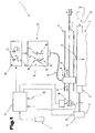
- FIG. 1 shows a device 1 for exposing a photosensitive material 2 with digital images 3 in a schematically simplified representation.
- the device 1 has for this purpose a transport device 4, with the aid of which the photosensitive material 2 can be moved in the feed direction 5.
- the photosensitive material 2 is formed by, for example, photographic paper or a film.
- a transport roller 7 operated by a motor 6 With the aid of a transport roller 7 operated by a motor 6, the material 2 is moved or positioned underneath an exposure head 8.
- the exposure head 8 can be moved back and forth along guides 9 oriented transversely or perpendicular to the feed direction 5 with the aid of an exposure head drive 10.
- the latter is alternately moved back in the direction 11 and in the direction 12, the material 2 being moved further in the feed direction 5 between the transverse movements of the exposure head 8 and being repositioned.
- There is such a line by line or pointwise exposure of the photosensitive material 2 by 8 light pulses are directed to the material 2 by the exposure head.
- the generation of the light pulses takes place in a light source unit 13 with light sources 14, 15, 16, which are preferably each formed by a light-emitting diode (LED). It is provided, for example, that the light source 14 of the generation of red light, the light source 15 of the generation of green light and the light source 16 of the generation of blue light, so that generates a triple of complementary primary colors by a triple of light sources 14, 15, 16 can be.
- the light sources 14, 15, 16 are to a coupling unit 17 summarized, wherein the light is merged or coupled into a single optical fiber 18.
- the light source unit 13 has a number of a plurality of such coupling units 17, the light of which is guided into the exposure head 8 through the optical fibers 18, which are combined to form a fiber bundle 19.
- each pixel can be exposed simultaneously with the three primary colors.
- the color components of the light sources 14, 15, 16 in that their light intensity is continuously variable, it is thus possible to produce any desired color on a pixel.
- each of the light sources 14, 15, 16 of each of the coupling units 17 has a drive circuit 20.
- Each of these drive circuits 20 comprises at least one digital / analog converter 21 and a timer 22.
- the execution of the exposure process of the device 1 by means of a central controller 23, the information of the digital image 3 in control signals for the transport device 4, the exposure head 10 and the driving circuits 20 for the light sources 14, 15, 16 converts.
- the controller 23 is connected to a displacement sensor 24 in connection.
- the device 1 additionally comprises a measuring cell 25 for measuring the light intensities of the exposure head 8.
- a measuring cell 25 for measuring the light intensities of the exposure head 8.
- the light sources 14, 15, 16 are formed by LEDs
- the strong, non-linearity of Connection, between drive current and light emission are measured.
- the correction parameters derived from this are taken into account during the exposure.
- This measuring cell 25 is preferably arranged in the region of a parking position of the exposure head 8 outside the actual exposure range of the device 1, so that measurements on the measuring cell 25 can also be carried out automatically.
- FIG. 2 shows a schematic diagram of one of the coupling-in units 17, according to FIG. 1.
- a fiber holder 27 for the inlet-side end of the optical fiber 18 is arranged on a frame 26 of the coupling-in unit 17.
- the optical fiber 18 is additionally attached in a socket 28, which can be inserted into the fiber holder 27 and fixed there.
- the fiber holder 27 has at one end a, corresponding to the longitudinal extension of the socket 28 of the optical fiber 18, aligned entrance hatch 29, through which the light of the light sources 14, 15, 16 enters or is coupled into the optical fiber.
- the light sources 14, 15, 16 are each held in a holder or a tube 30, 31, 32 and their light is focused in each case by a lens 33, 34, 35.
- the tubes 30, 31, 32 or optical axes 36, 37, 38 of the lenses 33, 34, 35 are aligned approximately star-shaped.
- the optical axis 38 of the lens 35 is aligned parallel and in alignment with respect to an optical axis 39 of the entrance hatch 29.
- the optical axes 36, 37 of the lenses 33, 34 with respect to the optical axis 39 of the engagement hatch 29 are obliquely aligned and passes the light of the light sources 14, 15 by deflection or reflection at an interference filter 40 or 41 in the entrance hatch 29th the fiber holder 27.
- the optical axes 36, 37 close with the optical axis 39 of the entrance hatch 29 preferably an angle of 60 °. This allows a very compact arrangement of the tubes 30, 31, 32 and the interference filter 40 with respect to the fiber holder 27th
- interference filter 40, 41 for deflecting the beam path of the light sources 14, 15 offers the advantage that light losses can be kept particularly low.
- interference filters are formed by alternating-layer systems, ie multiple layers with alternating high and low refractive indices. Since the layers are virtually free of absorption, a nearly lossless division of a spectral range to reflection and transmission is possible, the limit being determined by a steep edge of the transmission curve.
- a filter is used for the interference filter 40 whose spectral transmittance for red light is almost zero, while light of a smaller wavelength range, such as the green light of the light source 15 and the blue light of the light source 16 Interference filter can pass almost unattenuated.
- the red light of the light source 14 is reflected and passes through the entrance hatch 29 in the optical fiber 18.
- a filter is used as the interference filter 41 whose spectral transmittance for green Light is almost equal to 0, while the blue light of the light source 16 can pass almost lossless through the interference filter 41.
- the green light of the light source 15 is thus reflected to the interference filter 41 and passes through the engagement hatch 29 in the optical fiber 18.
- the peculiarity of the coupling unit 17 is thus that for the deflection of the beam path of the first light source 14 toward the entrance hatch 29 for the Optical fiber 18, an interference filter 40 is used whose spectral transmittance for the wavelength of the light of the light source 14 is almost 0, while the spectral transmittance for the wavelengths of light of the other light sources 15, 16, which must pass through the interference filter 40, almost equal 1 is.
- the second indifference filter 41 on the other hand, has a spectral transmittance which is almost equal to 0 for the wavelength of the light of the second light source 15, while the spectral transmittance of the light of the light source 16 which must pass through this indifference filter 41 is almost equal to 1.
- the light sources 14, 15, 16 in the respective tubes 30, 31, 32 can also be provided that their position with respect to the longitudinal extent of the respective tube 30, 31, 32 can be adjusted. Likewise, the position of the tubes 30, 31, 32 with respect to the frame 26 in the longitudinal extension of the tubes 30, 31, 32 are adjusted. This ensures that the light intensity that reaches the entrance hatch 29 of the fiber holder 27 has the maximum achievable value.
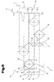
- FIG. 3 shows the exposure head 8 (shown in FIG. 1) arranged above the photosensitive material 2, shown in section.
- the photosensitive material 2 is guided in the region below the exposure head 8 via a table or a plate 42 with a flat upper side. This ensures that the material 2 is aligned parallel to the exit ends of the optical fibers 18.
- the optical fibers 18 guide the light into the exposure head 8.
- the optical fibers 18 each end in a socket 43, which are fastened in a carrier 44.
- the light from the optical fibers 18 is directed by the interposition of a lens system 45 on the photosensitive material 2.
- a mask 47 is arranged with hatches 48 or interposed.
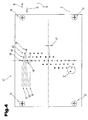
- FIG. 4 shows the mask 47 of the exposure head 8 according to FIG. 3.
- the gaps 48 are distributed in a grid-like manner on the mask 47, so that with respect to a direction perpendicular to the directions 11, 12 of the movement of the exposure head 8 successive gaps 48 are offset by a gap distance d 49.
- a total of 41 gaps 48 are present, so that when moving the exposure head 8 in one of the directions 11, 12 41 lines 40 of pixels on the material 2 can be exposed.
- this is indicated by way of example by the lines 50 shown in the upper area of the mask 47 for the direction of movement 11.
- the image inversion that occurs through the lens system 45 (FIG. 3) should be disregarded in the further description.
- the exit ends 46 of the optical waveguide fibers 18 In order to be able to position the exit ends 46 of the optical waveguide fibers 18 (FIG.
- the hatches 48 are in each case consecutive lines 50, also in the lateral direction, ie with respect to the directions 11, 12 added.
- this lateral displacement of the hatches 48 must be taken into account by a corresponding time delay of the transmission of the data of the digital image 3 to the drive circuit 20 (FIG.
- the mask 47 is preferably formed from a glass sheet provided with a coating. For exact mounting in the exposure head 8, the mask 47 also has centering marks 51.
- FIG. 5 shows a greatly enlarged detail of the mask 47 with two hatches 48, according to FIG. 4.
- the illustrated section shows two hatches 48 and dashed lines indicated exposure strips 52, as they are generated by the passage of the hatches 48 in the direction 11 on the photosensitive material 2.
- the exposure head 8 (FIG. 1) over the material 2 only every second line 50 is generated by the lines of the digital image 3 to be generated.
- the generation of corresponding intermediate lines 53 ensues, during a second movement of the exposure head 8, on the basis of the data of the digital image 3.
- successive lines 50, 53 thus have a line spacing z 54 whose value is equal to half the hatch distance d 49.
- This method of applying nested lines 50 and intermediate lines 53 is also referred to as interlacing.
- each hatch 48 perpendicular to the direction 11, 12 of the movement of the exposure head (8) has a height 55 whose value is greater than the line spacing z 54.
- the exposure strips 52 of lines 50 and exposure strips 56 of FIG Intermediate lines 53 between each successive lines 50 and intermediate lines 53 overlap each other. This can be avoided unwanted streaking.
- a width 57 of the hatch 48 has a value which is greater than the line spacing z 54. Both the height 55 and the width 57 of the hatch 48 thus extend beyond the maximum theoretical areal extent of a pixel. This corresponds just to a square with a side length which is equal to the line spacing z 54.
- width 57 of the hatch 48 is consequently also an overlap between adjacent Pixels within a line 50, 53 reached.
- the lateral overlap with respect to the direction 11, 12 is additionally increased by moving the exposure head 8 continuously over the photosensitive material 2 (FIG. 1). This overlap of the exposure areas of individual pixels in the lateral direction 11, 12 results from the path traveled by the exposure head 8 or the hatch 48 during the duration of an exposure pulse.
- the maximum duration of an exposure pulse is equal to the transit time for covering the width of an exposure point corresponding to FIG Line spacing z 54.
- a value between 60% and 95%, in particular 90%, of the propagation time for the width of an exposure point or the transit time for the distance of the line spacing z 54 is preferably selected.
- lateral contours 58, 59 correspond at least approximately to a Gaussian bell curve. Points of material 2 near the maximum width of the hatch 48, i. in an area near the width 57 of the hatch 48, are thus exposed to the exposure of a light pulse much longer than is the case for other points. This is symbolically indicated by exposure curves 60 of the exposure strips 52 and exposure curves 61 of the exposure strips 56, respectively. It is easy to see that in areas where exposure strips 52 and exposure strips 56 overlap one another, the exposure curves 60, 61 overlap, resulting in an overall exposure curve with approximately constant progression and no abrupt changes.
- the height 55 as well as the width 57 of the hatch 48 are preferably equal to 1.8 times the line spacing z 54.
- T difference stands for the time duration between the first exposure process and the second exposure process at the same location of the material 2.
- the method for correcting the intermittency effect thus consists in first producing at least one first line 50 of pixels 53 during a first movement of the exposure head 8 and subsequently producing at least one second line 53 of pixels 62 during a second movement of the exposure head the first row 50 and the second row 53 at least partially overlap each other.
- corrected image data for the second line 53 is calculated by compensating for the changed exposure effect of the second exposure process for each of the pixels 62. This compensation is effected by a change in the intensity and / or by the change in the pulse duration of the corresponding exposure pulse by a value which is proportional to the logarithm of the ratio of the time interval between the exposure of the pixel 63 and the exposure of the pixel 63 and a reference time interval.
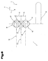
- FIG. 6 shows an enlarged section of the photosensitive material 2 with the lines 50 exposed thereon and an intermediate line 53.
- a pixel 62 of the intermediate line 53 and in each case a pixel 63 of the two adjacent rows 50 are indicated by a respective dashed square with the side length corresponding to the value of the line spacing z 54.
- Outlines of the hatches 48 are to be illustrated, the exposure takes place in accordance with the image data of the digital image 3 (FIG. 1), beyond the range of the theoretical maximum areal extent of the pixels 62, 63. The consequence is the overlap of the exposure strips 52, 56 already explained in the description of FIG. 5 (FIG. 5).
- the exposure of the photosensitive material 2 to the lines 50 occurs during movement of the exposure head 8 (FIG. 1) corresponding to the direction 11 (from left to right in FIG. 6).
- the exposure head 8 moves to the right edge of the image until the corresponding lines 50 have been completely exposed.
- the feeding head 8 changes its direction of movement in the direction 12 (from right to left in FIG. 6) and the intermediate line 53 is exposed until, finally, the pixel 62 is exposed at a second point in time.
- the time difference corresponds to a path 64 of the exposure head 8, as can be determined by detecting the position of the exposure head 8 by means of the encoder 24 ( Figure 1) and the speed of movement.
- the delay difference due to the lateral displacement of the hatches 48 would also have to be considered.
- this difference in transit time is negligible in relation to the total runtime.
- FIG. 7 shows a flowchart of the method for exposing digital images 3 with a correction of the intermittency effect.
- a first step 71 the image data is divided into image data corresponding to lines 50 and image data corresponding to intermediate lines 53 (FIGS. 5 and 6), in a further step 72 a recording of the movement sequence of the exposure head 8 and is carried out the advancing movement of the photosensitive material 2 (FIG. 1).
- a step 73 on the basis of this information, time intervals or differential times for adjacent pixels 62, 63 for lines 50 and intermediate lines 53 are determined.
- correction values for the exposure of the intermediate lines 53 are then calculated and thus new corrected image data for the intermediate lines 53 is determined.
- the control of the light sources 14, 15, 16, by the image data to the lines 50 and the intermediate lines 53 are alternately passed to the drive circuit 20.
- the exemplary embodiments show possible embodiments of the device or the method for generating a multicolored image from data of a digital image, it being noted at this point that the invention is not limited to the specifically illustrated embodiments of the same, but rather also various combinations of the individual embodiments are possible with each other and this possibility of variation due to the teaching of technical action by objective invention in the skill of working in this technical field expert. There are therefore also all possible embodiments, which are possible by combinations of individual details of the illustrated and described embodiment, the scope of protection.
Landscapes
- Health & Medical Sciences (AREA)
- General Health & Medical Sciences (AREA)
- Toxicology (AREA)
- Printers Or Recording Devices Using Electromagnetic And Radiation Means (AREA)
- Holo Graphy (AREA)
- Mechanical Optical Scanning Systems (AREA)
- Color, Gradation (AREA)
- Projection-Type Copiers In General (AREA)
Abstract
Description
Die Erfindung betrifft eine Vorrichtung und ein Verfahren zum Erzeugen eines mehrfarbigen Bildes aus Daten eines digitalen Bildes auf einem fotosensitivem Material, entsprechend den Merkmalen in den Oberbegriffen der Ansprüche 1, 24 und 33.The invention relates to an apparatus and a method for producing a multicolor image from data of a digital image on a photosensitive material, corresponding to the features in the preambles of
Aus dem Dokument US 6,452,696 B1 ist ein Verfahren und eine Vorrichtung zur Steuerung einer Mehrzahl von Lichtquellen in einem digitalen Drucker bekannt. Digitale Bilddaten werden dazu zur Belichtung eines fotosensitivem Materials verwendet, indem Licht punktweise auf das Fotopapier einwirkt. Der Lichtimpuls zur Belichtung eines Bildpunktes auf dem Fotopapier wird jeweils durch eine Leuchtdiode (LED), entsprechend der abgespeicherten, digitalen Bildinformation, erzeugt und durch eine Lichtleiterfaser in einen Belichtungskopf geleitet, durch den der Lichtimpuls schließlich auf das Fotopapier gerichtet wird. Die Austrittsenden einer Mehrzahl von Lichtleiterfasern sind in einem Rahmen des Belichtungskopfes unmittelbar nebeneinander liegend, aneinandergereiht. Die Anordnung der Austrittsenden der Lichtleiterfasern wird durch ein Linsensystem des Belichtungskopfes auf die Oberfläche des Fotopapiers abgebildet, sodass gleichzeitig eine Mehrzahl von Bildpunkten belichtet werden kann. Der Belichtungskopf wird quer über das Fotopapier bewegt, sodass während einer solchen Bewegung gleichzeitig eine Mehrzahl von Teilen von Bildpunkten erzeugt werden kann. Durch eine Transporteinrichtung wird sodann das Fotopapier um eine, der zuerst erzeugten Anzahl von Zeilen entsprechenden Länge, weitergeschoben, woraufhin eine weitere Folge von Zeilen von Bildpunkten, durch den sich über dem Papier bewegenden Belichtungskopf auf das Fotopapier übertragen wird. Aus dem Dokument US 6,452,696 B 1 ist außerdem bekannt, durch Ausführen von Testbelichtungen Korrekturtabellen zu bestimmen, durch die die ungleichförmige Belichtungswirkung, in Abhängigkeit von der Belichtungsintensität und der Belichtungsdauer, berücksichtigt werden kann. Damit wird der Effekt korrigiert, der darin besteht, dass die Belichtungswirkung mit einer ersten Belichtungsintensität und einer ersten Belichtungsdauer nicht gleich ist der Belichtungswirkung die beispielsweise erreicht wird, durch die Hälfte der ersten Belichtungsintensität über einen Zeitraum der doppelten ersten Belichtungszeit. Dieser Effekt wird auch als Reziprozitätsfehler bezeichnet. Es ist auch bereits bekannt, dass an den Kanten zwischen zwei aus nebeneinander liegenden Bildpunktzeilen bestehenden Streifen, die durch den Belichtungskopf erzeugt werden, andere Korrekturen erforderlich sind, als dies bei Bildpunktzeilen im Inneren eines Streifens der Fall ist. Um Streifenbildungen und damit Beeinträchtigungen der Bildqualität zu vermeiden.The document US Pat. No. 6,452,696 B1 discloses a method and a device for controlling a plurality of light sources in a digital printer. Digital image data are used to expose a photosensitive material by applying light point by point to the photographic paper. The light pulse for exposing a pixel on the photographic paper is in each case by a light-emitting diode (LED), according to the stored digital image information, generated and passed through an optical fiber in an exposure head, through which the light pulse is finally directed to the photographic paper. The outlet ends of a plurality of optical fibers are in a frame of the exposure head immediately adjacent to each other, strung together. The arrangement of the exit ends of the optical fibers is imaged by a lens system of the exposure head on the surface of the photographic paper, so that a plurality of pixels can be exposed simultaneously. The exposure head is moved across the photo paper so that at the same time a plurality of parts of pixels can be created during such movement. By means of a transport device, the photographic paper is then advanced by a length corresponding to the number of lines first produced, whereupon a further sequence of lines of pixels, through which the exposure head moving above the paper is transferred to the photographic paper. It is also known from US Pat. No. 6,452,696 B1 that, by carrying out test exposures, correction tables can be determined by which the non-uniform exposure effect, as a function of the exposure intensity and the exposure time, can be taken into account. Thus, the effect is corrected which is that the exposure effect having a first exposure intensity and a first exposure time is not equal to the exposure effect achieved, for example, by half the first exposure intensity over a period of twice the first exposure time. This effect is also called reciprocity failure. It is also already known that other corrections are required at the edges between two strips consisting of adjacent pixel lines, which are generated by the exposure head, than is the case with pixel lines in the interior of a strip is. To avoid banding and thus impairing the image quality.
Es ist die Aufgabe der Erfindung eine Vorrichtung bzw. ein Verfahren zum Erzeugen eines mehrfarbigen Bildes aus Daten eines digitalen Bildes auf einem fotosensitivem Material anzugeben, mit der bzw. dem Bilder hoher Qualität auf fotosensitiven Materialien erzeugt werden können.It is the object of the invention to provide an apparatus for producing a multicolor image from data of a digital image on a photosensitive material capable of producing high quality images on photosensitive materials.
Diese Aufgabe der Erfindung wird durch die Vorrichtung entsprechend den Merkmalen des Anspruchs 1 gelöst. Indem in der Vorrichtung Einkoppeleinheiten ausgebildet sind, durch die jeweils eine erste, eine zweite und eine dritte Lichtquelle mit einer einzigen Lichtleiterfaser verbunden sind und derart das Licht der drei Lichtquellen in eine einzige Lichtleiterfaser zusammengeführt wird, wobei die Farbe der ersten, der zweiten und der dritten Lichtquelle ein Tripel von komplementären Grundfarben bildet, wird der Vorteil erzielt, dass damit der Belichtungskopf nur noch ein Drittel der Anzahl der Lichtleiterfasern benötigt. Dies hat aber auch noch den weiteren Vorteil, dass damit die drei Farben zur Erzeugung eines Bildpunktes gleichzeitig aufgebracht werden und damit im Vergleich zu den sonst notwendigen, aufeinander folgenden Belichtungen der einzelnen Farben auf einem Bildpunkt, eine höhere Genauigkeit erreicht wird.This object of the invention is achieved by the device according to the features of claim 1. In that coupling devices are formed in the device, are connected by a respective first, a second and a third light source with a single optical fiber and thus the light of the three light sources is combined into a single optical fiber, wherein the color of the first, the second and the third light source forms a triple of complementary primary colors, the advantage is achieved so that the exposure head only requires a third of the number of optical fibers. However, this also has the further advantage that the three colors for generating a pixel are thus applied simultaneously, and thus a higher accuracy is achieved compared to the otherwise necessary, successive exposures of the individual colors on a pixel.
Der Vorteil der Ausbildung der Vorrichtung gemäß Anspruch 2 liegt darin, dass aufgrund der Charakteristik des Verlaufs des spektralen Transmissionsgrads der verwendeten Interferenzfilter, eine optimale Ausbeute des Lichts der verwendeten Lichtquellen erreicht wird.The advantage of the design of the device according to
Vorteilhaft sind auch die Weiterbildung der Vorrichtung gemäß den Ansprüchen 3 und 4, da damit eine sehr hohe Ausbeute der Lichtintensität der Lichtquellen erreicht werden kann.Also advantageous are the development of the device according to
Die Ausbildung der Vorrichtung gemäß Anspruch 5 hat den Vorteil, das derart die Lichtquellen die Interferenzfilter und die Eintrittsluke der Lichtfaser in der Einkoppeleinheit sehr kompakt und Platz sparend angeordnet werden können.The design of the device according to
Vorteilhaft ist auch die Ausbildung der Vorrichtung gemäß Anspruch 6. Diese ermöglicht eine einfache Montage bzw. Verbindung der Lichtleiterfasern mit der Einkoppeleinheit.Also advantageous is the design of the device according to
Durch die Weiterbildung der Vorrichtung gemäß Anspruch 7, wonach die Einkoppeleinheiten in einer stationären Lichtquelleneinheit angeordnet sind, wird der Vorteil erzielt, dass das Gewicht des Belichtungskopfes damit möglichst gering gehalten wird.Due to the development of the device according to
Vorteilhaft sind auch die Ausbildungen der Vorrichtung gemäß den Ansprüchen 8 und 9, da mit Leuchtdioden sehr präzise, kurze Lichtimpulse erzeugt werden können, sodass entsprechend hohe Geschwindigkeiten des Belichtungskopfes beim Bewegen über dem fotosensitivem Material möglich sind.Also advantageous are the embodiments of the device according to
Durch die Ausbildung der Vorrichtung gemäß Anspruch 10, stehen kontinuierlich veränderbare Lichtimpulse zur Belichtung zur Verfügung.Due to the design of the device according to
Durch die Ausbildung der Vorrichtung mit einer Messzelle zur Messung der Lichtintensitäten des Belichtungskopfes gemäß den Ansprüchen 11 und 12, wird der Vorteil erzielt, dass damit die erreichbaren Lichtintensitäten des Belichtungskopfes einfach überprüft werden können und insbesondere bei der Verwendung von Leuchtdioden als Lichtquellen deren nichtlinearer Zusammenhang zwischen Ansteuerstrom und Lichtintensität gemessen und bei der Belichtung von digitalen Bildern diese Beziehung berücksichtigt werden kann.By forming the device with a measuring cell for measuring the light intensities of the exposure head according to
Durch die Weiterbildung der Vorrichtung gemäß Anspruch 13, wonach ein Weggeber zur Erfassung der Position des Belichtungskopfes ausgebildet ist, wird der Vorteil erzielt, dass damit eine sehr präzise Steuerung der Bildpunkterzeugung entsprechend der seitlichen Position der entsprechenden Bildpunkte ermöglicht wird.The development of the device according to
Die Ausbildung der Vorrichtung gemäß Anspruch 14 hat den Vorteil, dass die Austrittsenden der Lichtleiterfasern nicht direkt über dem fotosensitivem Material bewegt werden müssen. Durch die Abbildung der Austrittsenden der Lichtleiterfasern mit dem vorgesehenen Linsensystem, können auch die Ungenauigkeiten infolge der Divergenz der austretenden Lichtbündel aus den Lichtleiterfasern vermieden werden.The design of the device according to
Durch die gemäß Anspruch 15 vorgesehene Maske wird erreicht, dass sowohl die Position als auch die Form der Bildpunkte mit hoher Präzision festgelegt werden kann und mechanische Ungenauigkeiten der Montage der Lichtleiterfasern in dem Belichtungskopf aufgehoben werden.The mask provided according to
Vorteilhaft sind auch die Weiterbildungen der Vorrichtung gemäß den Ansprüchen 16 und 17, da es damit möglich ist, das Auftragen der Bildpunkte durch abwechselndes Erzeugen von Zeilen und Zwischenzeilen, indem nur jeweils jede zweite Zeile des digitalen Bildes belichtet wird und daran anschließend entsprechende Zwischenzeilen belichtet werden, auszuführen.Also advantageous are the developments of the device according to
Durch die Ausbildung der Vorrichtung gemäß den Ansprüchen 18 und 19, ist in vorteilhafter Weise eine Überlappung von jeweils aufeinander folgenden Zeilen bzw. Zwischenzeilen möglich, wodurch Bildfehler infolge von Ungenauigkeiten, die sich durch horizontale Streifenbildungen bemerkbar machen könnten, vermieden werden können.Due to the design of the device according to
Durch die Ausbildung der Vorrichtung gemäß den Ansprüchen 20 und 21 wird der Vorteil erzielt, das damit auch eine der Überlappung von Zeilen bzw. Zwischenzeilen entsprechende Überlappung in seitlicher Richtung zwischen einander innerhalb einer Zeile benachbarten Bildpunkten erreicht wird. Die Ausbildung vertikaler Streifen, die sich als entsprechende Bildfehler bemerkbar machen könnten, werden damit vermieden.The embodiment of the device according to
Durch die Weiterbildung der Vorrichtung gemäß Anspruch 22, wonach seitliche Konturen der Luken in der Maske annähernd einer Gaußschen Glockenkurve entsprechen, wird erreicht, dass auch bei unpräziser Vorschubbewegung der Transporteinrichtung ein möglichst gleichmäßiger Verlauf der Gesamtbelichtung zwischen zwei einander benachbarten Zeilen bzw. Zwischenzeilen weitestgehend erhalten bleibt.Due to the development of the device according to
Die Ausbildung der Vorrichtung gemäß Anspruch 23 hat den Vorteil, dass mit den durch beschichtete Glasblättchen gebildeten Masken, Masken mit sehr hoher Präzision zur Verfügung stehen.The design of the device according to
Die Aufgabe der Erfindung wird eigenständig auch durch das Verfahren entsprechend den Merkmalen des Anspruches 24 gelöst. Von Vorteil ist dabei, dass mit einem Drittel der Lichtleiterfasern das Auslangen gefunden werden kann und gleichzeitig eine höhere Genauigkeit der Belichtung der einzelnen Bildpunkte des digitalen Bildes erzielbar ist.The object of the invention is solved independently by the method according to the features of
Vorteilhafte Weiterbildungen des Verfahrens sind auch in den Ansprüchen 25 bis 32 beschrieben.Advantageous developments of the method are also described in
Eine für sich eigenständige Lösung der Aufgabe der Erfindung ist auch durch das Verfahren gemäß Anspruch 33 beschrieben. Von Vorteil ist dabei, dass damit gleichzeitig eine gleichmäßig Gesamtbelichtungswirkung zwischen aufeinander folgenden Zeilen bzw. Zwischenzeilen des digitalen Bildes erreicht werden kann.An independent solution of the object of the invention is also described by the method according to
Vorteilhafte Ausbildungen des Verfahrens sind auch durch die Ansprüche 34 bis 40 beschrieben.Advantageous embodiments of the method are also described by the
Zum besseren Verständnis der Erfindung wird diese anhand der nachfolgenden Figuren näher erläutert.For a better understanding of the invention, this will be explained in more detail with reference to the following figures.
Es zeigen in schematisch vereinfachter Darstellung:
- Fig. 1
- eine Vorrichtung zum Belichten eines fotosensitivem Materials mit digitalen Bildern;
- Fig. 2
- eine Prinzipdarstellung einer Einkoppeleinheit, gemäß Fig. 1;
- Fig. 3
- den über dem fotosensitiven Material angeordneten Belichtungskopf (gemäß Fig. 1), geschnitten dargestellt;
- Fig. 4
- die Maske des Belichtungskopfes gemäß Fig. 3;
- Fig. 5
- ein stark vergrößertes Detail der Maske mit zwei Luken, gemäß Fig. 4;
- Fig. 6
- einen vergrößerten Ausschnitt des photosensitiven Materials mit den darauf belichteten Zeilen und einer Zwischenzeile;
- Fig. 7
- ein Ablaufschema des Verfahrens zum Belichten von digitalen Bildern mit einer Korrektur des Intermittenz-Effektes.
- Fig. 1
- an apparatus for exposing a photosensitive material to digital images;
- Fig. 2
- a schematic diagram of a coupling unit, according to FIG. 1;
- Fig. 3
- the exposure head arranged above the photosensitive material (according to FIG. 1) is shown in section;
- Fig. 4
- the mask of the exposure head of FIG. 3;
- Fig. 5
- a greatly enlarged detail of the mask with two hatches, as shown in FIG. 4;
- Fig. 6
- an enlarged section of the photosensitive material with the lines exposed thereon and an intermediate line;
- Fig. 7
- a flow chart of the method for exposing digital images with a correction of the Intermittenz effect.
Einführend sei festgehalten, dass in den unterschiedlich beschriebenen Ausführungsformen gleiche Teile mit gleichen Bezugszeichen bzw. gleichen Bauteilbezeichnungen versehen werden, wobei die in der gesamten Beschreibung enthaltenen Offenbarungen sinngemäß auf gleiche Teile mit gleichen Bezugszeichen bzw. gleichen Bauteilbezeichnungen übertragen werden können. Auch sind die in der Beschreibung gewählten Lageangaben, wie z.B. oben, unten, seitlich usw. auf die unmittelbar beschriebene sowie dargestellte Figur bezogen und sind bei einer Lageänderung sinngemäß auf die neue Lage zu übertragen. Weiters können auch Einzelmerkmale oder Merkmalskombinationen aus den gezeigten und beschriebenen unterschiedlichen Ausführungsbeispielen für sich eigenständige, erfinderische oder erfindungsgemäße Lösungen darstellen.By way of introduction, it should be noted that in the differently described embodiments, the same parts are provided with the same reference numerals or the same component names, wherein the disclosures contained in the entire description can be mutatis mutandis to the same parts with the same reference numerals or component names. Also, the location information chosen in the description, such as top, bottom, side, etc. related to the immediately described and illustrated figure and are to be transferred to the new situation mutatis mutandis when a change in position. Furthermore, individual features or combinations of features from the different exemplary embodiments shown and described can also represent independent, inventive or inventive solutions.
Die Fig. 1 zeigt eine Vorrichtung 1 zum Belichten eines fotosensitivem Materials 2 mit digitalen Bildern 3 in schematisch vereinfachter Darstellung.1 shows a device 1 for exposing a
Die Vorrichtung 1 verfügt dazu über eine Transporteinrichtung 4, mit deren Hilfe das fotosensitive Material 2 in Vorschubrichtung 5 bewegt werden kann. Das fotosensitive Material 2 wird beispielsweise durch Fotopapier oder einen Film gebildet. Mit Hilfe einer, durch einen Motor 6 betriebenen Transportwalze 7 wird das Material 2 unterhalb eines Belichtungskopfes 8 vorwärts bewegt bzw. positioniert. Der Belichtungskopf 8 ist entlang von quer bzw. senkrecht zur Vorschubrichtung 5 ausgerichteten Führungen 9 mit Hilfe eines Belichtungskopfsantriebs 10 hin und her bewegbar. Zur Belichtung des Materials 2 mit dem Belichtungskopf 8 wird dieser alternierend in Richtung 11 hin und in Richtung 12 wieder zurückbewegt, wobei zwischen den Querbewegungen des Belichtungskopf 8 das Material 2 in Vorschubrichtung 5 weiterbewegt und neu positioniert wird. Es erfolgt derart eine zeilenweise bzw. punktweise Belichtung des fotosensitivem Materials 2, indem durch den Belichtungskopf 8 Lichtimpulse auf das Material 2 gerichtet werden.The device 1 has for this purpose a
Die Erzeugung der Lichtimpulse erfolgt in einer Lichtquelleneinheit 13 mit Lichtquellen 14, 15, 16, die bevorzugt jeweils durch eine Leuchtdiode (LED ) gebildet sind. Dabei ist beispielsweise vorgesehen, dass die Lichtquelle 14 der Erzeugung von rotem Licht, die Lichtquelle 15 der Erzeugung von grünem Licht und die Lichtquelle 16 der Erzeugung von blauem Licht dient, sodass durch ein Tripel von Lichtquellen 14, 15, 16 ein Tripel komplementärer Grundfarben erzeugt werden kann. Die Lichtquellen 14, 15, 16 sind zu einer Einkoppeleinheit 17 zusammengefasst, wobei deren Licht in eine einzige Lichtleiterfaser 18 zusammengeführt bzw. eingekoppelt wird. Die Lichtquelleneinheit 13 weist eine Anzahl von mehreren solcher Einkoppeleinheiten 17 auf, deren Licht durch die Lichtleiterfasern 18, die zu einem Faserbündel 19 zusammengefasst sind, in den Belichtungskopf 8 geleitet wird. Entsprechend der Anzahl von Lichtleiterfasern 18 ist es somit möglich, eine der Anzahl der Einkoppeleinheiten 17 entsprechende Anzahl von Zeilen auf dem fotosensitivem Material 2 gleichzeitig zu belichten, wobei jeder Bildpunkt gleichzeitig mit den drei Grundfarben belichtet werden kann. Durch entsprechende Mischung der Farbanteile der Lichtquellen 14, 15, 16, indem deren Lichtintensität kontinuierlich veränderbar ist, kann so auf einem Bildpunkt jede beliebige Farbe erzeugt werden.The generation of the light pulses takes place in a
Zur Erzeugung der Lichtimpulse weist jede der Lichtquellen 14, 15, 16 einer jeder der Einkoppeleinheiten 17 eine Ansteuerschaltung 20 auf. Jede dieser Ansteuerschaltungen 20 umfasst zumindest einen Digital-/Analogwandler 21 und einen Zeitgeber 22. Die Ausführung des Belichtungsvorgangs der Vorrichtung 1 erfolgt mit Hilfe einer zentralen Steuerung 23, die die Informationen des digitalen Bildes 3 in Steuersignale für die Transporteinrichtung 4, den Belichtungskopfantrieb 10 und die Ansteuerschaltungen 20 für die Lichtquellen 14, 15, 16 umwandelt. Zur Bestimmung der momentanen Position des Belichtungskopfs 8 bzw. der Faserenden der Lichtleiterfasern 18 steht die Steuerung 23 mit einen Weggeber 24 in Verbindung.To generate the light pulses, each of the
Die Vorrichtung 1 umfasst zusätzlich eine Messzelle 25 zur Messung der Lichtintensitäten des Belichtungskopfes 8. Insbesondere im Fall, dass die Lichtquellen 14, 15, 16 durch LED's gebildet sind, kann durch Vermessung der Lichtintensitäten mit Hilfe der Messzelle 25 die starke, Nicht-Linearität des Zusammenhanges, zwischen Ansteuerstrom und Lichtemission gemessen werden. Die daraus abgeleiteten Korrekturparameter werden während der Belichtung berücksichtigt. Durch periodisches Wiederholen entsprechender Vermessungen mit der Messzelle 25 können aber auch Veränderungen infolge der Alterung bzw. der thermischen Belastungen der LED's kompensiert werden. Diese Messzelle 25 ist vorzugsweise im Bereich einer Parkposition des Belichtungskopfes 8 außerhalb des eigentlichen Belichtungsbereiches der Vorrichtung 1 angeordnet, sodass Vermessungen an der Messzelle 25 auch automatisiert durchgeführt werden können.The device 1 additionally comprises a measuring
Die Fig. 2 zeigt eine Prinzipdarstellung einer der Einkoppeleinheiten 17, gemäß Fig. 1.FIG. 2 shows a schematic diagram of one of the coupling-in
An einem Rahmen 26 der Einkoppeleinheit 17 ist eine Faserhaltung 27 für das Einlassseitige Ende der Lichtleiterfaser 18 angeordnet. Die Lichtleiterfaser 18 ist dazu zusätzlich in einer Fassung 28 befestigt, wobei diese in die Faserhalterung 27 eingeschoben und dort fixiert werden kann. Die Faserhalterung 27 weist an einem Ende eine, entsprechend der Längserstreckung der Fassung 28 der Lichtleiterfaser 18, ausgerichtete Eintrittsluke 29 auf, durch die das Licht der Lichtquellen 14, 15, 16 in die Lichtleiterfaser eintritt bzw. in diese eingekoppelt wird. Die Lichtquellen 14, 15, 16 sind jeweils in einer Halterung bzw. einem Tubus 30, 31, 32 gefasst und wird deren Licht jeweils durch eine Linse 33, 34, 35 fokussiert. Die Tuben 30, 31, 32 bzw. optische Achsen 36, 37, 38 der Linsen 33, 34, 35 sind dabei annäherungsweise sternförmig ausgerichtet. Die optische Achse 38 der Linse 35 ist parallel und fluchtend bezüglich einer optischen Achse 39 der Eintrittsluke 29 ausgerichtet. Im Gegensatz dazu sind die optischen Achsen 36, 37 der Linsen 33, 34 gegenüber der optischen Achse 39 der Eingriffsluke 29 schräg ausgerichtet und gelangt das Licht der Lichtquellen 14, 15 durch Umlenkung bzw. Reflexion an einem Interreferenzfilter 40 bzw. 41 in die Eintrittsluke 29 der Faserhalterung 27. Die optischen Achsen 36, 37 schließen mit der optischen Achse 39 der Eintrittsluke 29 bevorzugt einen Winkel von 60 ° ein. Dies ermöglicht eine sehr kompakte Anordnung der Tuben 30, 31, 32 und der Interferenzfilter 40 in Bezug auf die Faserhalterung 27.On a
Die Verwendung der Interferenzfilter 40, 41 zur Umlenkung des Strahlengangs der Lichtquellen 14, 15 bietet den Vorteil, dass damit Lichtverluste besonders gering gehalten werden können. Derartige Interferenzfilter werden durch Wechselschichtsysteme, d.h. Mehrfachschichten mit abwechselnd hoher und niedriger Brechzahl gebildet. Da die Schichten praktisch absorptionsfrei sind, ist eine nahezu verlustlose Aufteilung eines Spektralbereichs auf Reflexion und Transmission möglich, wobei die Grenze durch eine steile Kante der Transmissionskurve bestimmt wird. Zur Umlenkung des roten Lichts der Lichtquelle 14 wird für den Interferenzfilter 40 demnach ein Filter verwendet, dessen spektraler Transmissionsgrad für rotes Licht nahezu gleich null ist, während Licht eines kleineren Wellenbereichs, wie das grüne Licht der Lichtquelle 15 und das blaue Licht der Lichtquelle 16 den Interferenzfilter nahezu ungeschwächt passieren kann. Das rote Licht der Lichtquelle 14 hingegen wird reflektiert und tritt durch die Eintrittsluke 29 in die Lichtleiterfaser 18. Analog dazu wird als Interferenzfilter 41 ein Filter verwendet, dessen spektraler Transmissionsgrad für grünes Licht nahezu gleich 0 ist, während das blaue Licht der Lichtquelle 16 nahezu verlustfrei durch den Interferenzfilter 41 hindurchtreten kann. Das grüne Licht der Lichtquelle 15 wird demnach an den Interferenzfilter 41 reflektiert und gelangt durch die Eingriffsluke 29 in die Lichtleiterfaser 18. Die Besonderheit der Einkoppeleinheit 17 besteht somit darin, dass für das Umlenken des Strahlengangs der ersten Lichtquelle 14 hin auf die Eintrittsluke 29 für den Lichtleiterfaser 18 ein Interferenzfilter 40 verwendet wird, dessen spektraler Transmissionsgrad für die Wellenlänge des Lichtes der Lichtquelle 14 nahezu gleich 0 ist, während der spektrale Transmissionsgrad für die Wellenlängen des Lichts der weiteren Lichtquellen 15, 16, das durch den Interferenzfilter 40 hindurchtreten muss, nahezu gleich 1 ist. Der zweite Indifferenzfilter 41 hingegen weist einen spektralen Transmissionsgrad auf, der für die Wellenlänge des Lichts der zweiten Lichtquelle 15 nahezu gleich 0 ist, während der spektrale Transmissionsgrad des Lichts der Lichtquelle 16 das durch diesen Indifferenzfilter 41 hindurchtreten muss, nahezu gleich 1 ist.The use of the
Für die Anordnung der Lichtquellen 14, 15, 16 in den jeweiligen Tuben 30, 31, 32 kann auch vorgesehen sein, dass deren Lage bezüglich der Längserstreckung des jeweiligen Tubus 30, 31, 32 justiert werden kann. Ebenso kann die Lage der Tuben 30, 31, 32 bezüglich des Rahmens 26 in Längserstreckung der Tuben 30, 31, 32 justiert werden. Damit wird erreicht, dass die Lichtintensität, die in die Eintrittsluke 29 der Faserhalterung 27 gelangt, den maximal erreichbaren Wert hat.For the arrangement of the
Die Fig. 3 zeigt den über dem fotosensitiven Material 2 angeordneten Belichtungskopf 8 (gemäß Fig. 1), geschnitten dargestellt.FIG. 3 shows the exposure head 8 (shown in FIG. 1) arranged above the
Das fotosensitive Material 2 wird im Bereich unterhalb des Belichtungskopfes 8 über einen Tisch bzw. eine Platte 42 mit einer ebenen Oberseite geführt. Damit wird sichergestellt, dass das Material 2 parallel bezüglich den Austrittsenden der Lichtleiterfasern 18 ausgerichtet ist. Von der stationär angeordneten Lichtquelleneinheit 13 (Fig. 1) führen die Lichtleiterfasern 18 das Licht in den Belichtungskopf 8. Die Lichtleiterfasern 18 enden jeweils in einer Fassung 43, die in einem Träger 44 befestigt sind. Das Licht aus den Lichtleiterfasern 18 wird durch Zwischenschaltung eines Linsensystems 45 auf das fotosensitive Material 2 gerichtet. Zwischen den dem Material 2 zugewandten Austrittsenden 46 der Lichtleiterfasern 8 und dem Linsensystems 45 ist eine Maske 47 mit Luken 48 angeordnet bzw. zwischengeschaltet.The
Durch Verwendung dieser Maske 47 werden Ungenauigkeiten in der Positionierung der Austrittsenden 46 der Lichtleiterfasern 18 ausgeglichen. Sowohl das Einsetzen der Lichtleiterfasern 18 in die Fassungen 43 als auch das Einsetzen dieser Fassungen 43 in den Träger 44 ist mit mechanischen Ungenauigkeiten verbunden, die durch die mit den Luken 48 versehene Maske 47 zur Gänze aufgehoben werden können und somit nur noch Ungenauigkeiten von der Herstellung der Maske 47 selbst verbleiben. Die Luken 48 in der Maske 47 wirken jeweils als Blenden für das aus den Austrittsenden 46 austretende Licht und kann damit sowohl die Form der einzelnen Pixelpunkte als auch deren relativer Abstand sehr genau festgelegt werden. Indem die Lucken 48 der Maske 47 durch das Linsensystem 45 im Verhältnis 1:1 auf dem Material 2 abgebildet werden, kann auch auf dem Material 2 die gleiche Genauigkeit der gegenseitigen Abstände als auch die Form der Bildpunkte erreicht werden.By using this
Die Fig. 4 zeigt die Maske 47 des Belichtungskopfes 8 gemäß Fig. 3.FIG. 4 shows the
Die Lucken 48 sind rasterförmig auf der Maske 47 verteilt, sodass bezüglich einer Richtung senkrecht zu den Richtungen 11, 12 der Bewegung des Belichtungskopfes 8 jeweils aufeinander folgende Lucken 48 um einen Luckenabstand d 49 versetzt sind. Im dargestellten Ausführungsbeispiel sind insgesamt 41 Lucken 48 vorhanden, sodass bei einer Bewegung des Belichtungskopfes 8 in einer der Richtungen 11, 12 41 Zeilen 40 von Bildpunkten auf dem Material 2 belichtet werden können. In der Fig. 4 ist dies durch die im oberen Bereich der Maske 47 dargestellten Zeilen 50 für die Bewegungsrichtung 11 beispielhaft angedeutet. Der Einfachheit halber soll die durch das Linsensystem 45 (Fig. 3) erfolgende Bildumkehr in der weiteren Beschreibung unberücksichtigt bleiben. Um die Austrittsenden 46 der Lichtleiterfasern 18 (Fig. 3) ohne gegenseitige räumliche Behinderung jeweils über einer der Lucken 48 positionieren zu können, sind die Luken 48 zu jeweils aufeinander folgenden Zeilen 50 zusätzlich auch in seitlicher Richtung, d.h. bezüglich der Richtungen 11, 12 gegeneinander versetzt. Bei der Ansteuerung der Lichtquellen 14, 15, 16 unterschiedlicher Lichtleiterfasern 18 ist diese seitliche Versetzung der Luken 48 durch eine entsprechende zeitliche Verzögerung der Übertragung der Daten des digitalen Bildes 3 zu der Ansteuerschaltung 20 (Fig. 1) zu berücksichtigen. Die Maske 47 wird vorzugsweise aus einem mit einer Beschichtung versehenen Glasblättchen gebildet. Zur exakten Montage im Belichtungskopf 8, weist die Maske 47 auch Zentriermarken 51 auf.The
Fig. 5 zeigt ein stark vergrößertes Detail der Maske 47 mit zwei Luken 48, gemäß Fig. 4.FIG. 5 shows a greatly enlarged detail of the
Der dargestellte Ausschnitt zeigt zwei Luken 48 und strichliert angedeutet Belichtungsstreifen 52, wie sie durch das Vorbeibewegen der Luken 48 in Richtung 11 auf dem photosensitiven Material 2 erzeugt werden. Erfindungsgemäß ist vorgesehen, dass während einer ersten Bewegung des Belichtungskopfes 8 (Fig. 1) über das Material 2 von den zu erzeugenden Zeilen des digitalen Bildes 3 nur jede zweite Zeile 50 erzeugt wird. Nachdem das Material 2 in Vorschubrichtung 5 entsprechend weiterbewegt wurde, erfolgt daraufhin, während einer zweiten Bewegung des Belichtungskopfs 8, die Erzeugung von entsprechenden Zwischenzeilen 53, auf Basis der Daten des digitalen Bildes 3. Bezüglich der Vorschubrichtung 5 aufeinander folgende Zeilen 50, 53 haben somit einen Zeilenabstand z 54, dessen Wert gleich ist der Hälfte des Lukenabstands d 49. Dieses Verfahren des Auftragens von ineinander verschachtelten Zeilen 50 und Zwischenzeilen 53 wird auch als Interlacing bezeichnet. Dabei wird vorzugsweise ein Belichtungskopf 8 mit einer ungeradzahligen Anzahl von Lichtleiterfasern 18 bzw. von Luken 48 verwendet, sodass die Transporteinrichtung 4 mit einer jeweils gleichen Vorschublänge im Ausmaß des Produkts der Anzahl der Lichtleiterfasern 18 und der Hälfte des Lukenabstandes d 49 betrieben werden kann (Vorschublänge = Anzahl Lichtleiterfasern * d/2).The illustrated section shows two
Erfindungsgemäß weist jede Luke 48 senkrecht bezüglich der Richtung 11, 12 der Bewegung des Belichtungskopfes (8) eine Höhe 55 auf, deren Wert größer ist als der Zeilenabstand z 54. Dies hat zur Folge, dass die Belichtungsstreifen 52 von Zeilen 50 und Belichtungsstreifen 56 von Zwischenzeilen 53 zwischen jeweils aufeinander folgenden Zeilen 50 und Zwischenzeilen 53 einander überlappen. Damit können unerwünschte Streifenbildungen vermieden werden. Bei Luken 48 deren Höhe 55 gleich ist dem theoretisch maximalen Wert der Höhe eines Bildpunktes, nämlich gleich dem Zeilenabstand z 54, kann es in Folge einer nicht ausreichend exakten Vorwärtsbewegung des Materials 2 durch die Transporteinrichtung 4 zu unbelichteten Luken kommen, die sich als Streifen im Bild bemerkbar machen. Weiters ist vorgesehen, dass eine Breite 57 der Luke 48 einen Wert hat, der größer ist als der Zeilenabstand z 54. Sowohl die Höhe 55 als auch die Breite 57 der Luke 48 reichen somit über die maximale theoretische flächenmäßige Ausdehnung eines Bildpunktes hinaus. Diese entspricht gerade einem Quadrat mit einer Seitenlänge, die gleich ist dem Zeilenabstand z 54. Durch die so gewählte Breite 57 der Luke 48 wird folglich auch eine Überlappung zwischen benachbarten Bildpunkten innerhalb einer Zeile 50, 53 erreicht. Die seitliche Überlappung bezüglich der Richtung 11, 12 wird zusätzlich noch dadurch erhöht, dass der Belichtungskopf 8 kontinuierlich über das photosensitive Material 2 bewegt wird (Fig. 1). Diese Überlappung der Belichtungsbereiche von einzelnen Bildpunkten in seitlicher Richtung 11, 12 ergibt sich aus dem während der Dauer eines Belichtungsimpulses zurückgelegten Weg des Belichtungskopfes 8 bzw. der Luke 48. Die maximale Dauer eines Belichtungsimpulses ist gleich der Laufzeit zum Zurücklegen der Breite eines Belichtungspunktes entsprechend dem Zeilenabstand z 54. Für die Dauer der Belichtungsimpulse wird bevorzugt ein Wert zwischen 60 % und 95 %, insbesondere 90 %, der Laufzeit für die Breite eines Belichtungspunktes bzw. der Laufzeit für die Strecke des Zeilenabstands z 54 gewählt.According to the invention, each
Betreffend die Form der Luke 48 ist vorgesehen, dass seitliche Konturen 58, 59 zumindest annähernd einer Gaußschen Glockenkurve entsprechen. Punkte des Materials 2 in der Nähe der maximalen Breite der Luke 48, d.h. in einem Bereich in der Nähe der Breite 57 der Luke 48, sind somit wesentlich länger der Belichtung durch einen Lichtimpuls ausgesetzt, als dies für andere Punkte der Fall ist. Dies wird symbolisch durch Belichtungskurven 60 der Belichtungsstreifen 52 bzw. Belichtungskurven 61 der Belichtungsstreifen 56 angedeutet. Es ist leicht zu erkennen, dass in Bereichen, wo Belichtungsstreifen 52 und Belichtungsstreifen 56 einander überlappen, eine Überlagerung der Belichtungskurven 60, 61 erfolgt und sich somit eine Gesamtbelichtungskurve mit annähernd konstantem Verlauf und ohne sprunghafte Änderungen ergibt. Auch Ungenauigkeiten, die infolge von nicht exakt ausgeführten Vorschüben durch die Transporteinrichtung 4 auftreten können, haben dadurch auf die Gesamtbelichtungskurve nur sehr geringe Auswirkung und sind folglich im Erscheinungsbild des fertig belichteten Bildes praktisch nicht erkennbar. Die Höhe 55 als auch die Breite 57 der Luke 48 sind vorzugsweise gleich dem 1,8-fachen des Zeilenabstands z 54.Regarding the shape of the
Wegen der Überlappung der Belichtungsstreifen 56 von Zwischenzeilen 53 mit den Belichtungsstreifen 52 der Zeilen 50 werden Stellen des Materials 2, die sich in den Überlappungsbereich befinden, mit einem zeitlichen Abstand zweimal hintereinander belichtet. Da die Belichtungswirkung in einem solchen Fall beim zweiten Belichtungsvorgang eine andere ist, als wenn eine Stelle zum ersten Mal belichtet wird, ist erfindungsgemäß vorgesehen, dass eine Kompensation durch eine Korrektur der Lichtintensitäten und/oder der Impulsdauer der Lichtimpulse vorgenommen wird. Die unterschiedliche Belichtungswirkung von zwei aufeinander folgenden Belichtungen eines photosensitiven Materials ist als so genannter Intermittenz-Effekt von photophysikalischen Belichtungssystemen bekannt. Die Berechnung der Korrekturwerte für die Intensität der Belichtung erfolgt anhand einer Funktion der Form: ![]()
- Stärke: einstellbare Korrekturwirkung
- T-Differenz: aktuelles Zeitintervall
- T-Nominal: Referenz-Zeitinterfall
- Strength: adjustable correction effect
- T difference: current time interval
- T-Nominal: reference time interval
Die Werte für "Stärke" und "T-Nominal" können durch Testbelichtungen ermittelt werden. T-Differenz steht für die zeitliche Dauer zwischen dem ersten Belichtungsvorgang und dem zweiten Belichtungsvorgang an der gleichen Stelle des Materials 2.The values for "Thickness" and "T-Nominal" can be determined by test exposures. T difference stands for the time duration between the first exposure process and the second exposure process at the same location of the
Das Verfahren zur Korrektur des Intermittenzeffektes besteht somit darin, dass zunächst während einer ersten Bewegung des Belichtungskopfes 8 zumindest eine erste Zeile 50 von Bildpunkten 53 erzeugt wird und daran anschließend während einer zweiten Bewegung des Belichtungskopfes zumindest eine zweite Zeile 53 von Bildpunkten 62 erzeugt wird, wobei die erste Zeile 50 und die zweite Zeile 53 einander zumindest teilweise überlappen. Vor dem Erzeugen der zweiten Zeile 53 werden korrigierte Bilddaten für die zweite Zeile 53 berechnet, indem die veränderte Belichtungswirkung des zweiten Belichtungsvorganges für einen jeden der Bildpunkte 62 kompensiert wird. Diese Kompensation erfolgt durch eine Änderung der Intensität und/oder durch die Änderung der Impulsdauer des entsprechenden Belichtungsimpulses um einen Wert der proportional ist zum Logarithmus aus dem Verhältnis des Zeitintervalls zwischen der Belichtung des Bildpunktes 63 und der Belichtung des Bildpunktes 63 und einem Referenz-Zeitintervall.The method for correcting the intermittency effect thus consists in first producing at least one
Die Fig. 6 zeigt einen vergrößerten Ausschnitt des photosensitiven Materials 2 mit den darauf belichteten Zeilen 50 und einer Zwischenzeile 53.FIG. 6 shows an enlarged section of the
Anhand dieser Darstellung soll die Korrektur des oben erwähnten Intermittenz-Effektes näher beschrieben werden. Ein Bildpunkt 62 der Zwischenzeile 53 und jeweils ein Bildpunkt 63 der beiden benachbarten Zeilen 50 sind durch je ein strichliertes Quadrat mit der Seitenlänge entsprechend dem Wert des Zeilenabstands z 54 angedeutet. Wie durch die ebenfalls eingezeichneten Umrisse der Luken 48 illustriert werden soll, erfolgt die Belichtung entsprechend der Bilddaten des digitalen Bildes 3 (Fig. 1), über den Bereich der theoretischen maximalen flächenmäßigen Ausdehnung der Bildpunkte 62, 63 hinaus. Die Folge ist die, bereits in der Beschreibung zur Fig. 5 erläuterte Überlappung der Belichtungsstreifen 52, 56 (Fig. 5).Based on this representation, the correction of the above-mentioned Intermittenz effect will be described in more detail. A
Es sei nun angenommen, dass die Belichtung des photosensitiven Materials 2 mit den Zeilen 50 während einer Bewegung des Belichtungskopfes 8 (Fig. 1) entsprechend der Richtung 11 (gemäß Fig. 6 von links nach rechts) erfolgt. Entsprechend der seitlichen Position der Bildpunkte 63 werden diese zu einem ersten Zeitpunkt belichtet, woraufhin sich der Belichtungskopf 8 bis zum rechten Rand des Bildes bewegt, bis die entsprechenden Zeilen 50 vollständig belichtet worden sind. Es erfolgt sodann ein Vorschub des photosensitiven Materials 2 in Vorschubrichtung 5, sodass anschließend die Zwischenzeilen 53 belichtet werden können. Der Beliehtungskopf 8 (Fig. 1) wechselt seine Bewegungsrichtung in Richtung 12 (gemäß Fig. 6 von rechts nach links) und es erfolgt die Belichtung der Zwischenzeile 53 bis schließlich zu einem zweiten Zeitpunkt der Bildpunkt 62 belichtet wird. Durch Messung bzw. Vorausberechnung der Zeitdifferenz zwischen dem ersten Zeitpunkt der Belichtung der Bildpunkte 63 und dem zweiten Zeitpunkt der Belichtung des Bildpunkts 62 ist es möglich, einen Korrekturwert für den zur Belichtung des Bildpunktes 62 erforderlichen Lichtimpulses zu berechnen und bei der Ansteuerung der Lichtquellen 14, 15, 16 (Fig. 1) mit zu berücksichtigen. Die Zeitdifferenz entspricht einem Weg 64 des Belichtungskopfes 8, wie sie durch Erfassung der Position des Belichtungskopfes 8 mit Hilfe des Weggebers 24 (Fig. 1) und der Bewegungsgeschwindigkeit bestimmt werden kann. Für eine exakte Bestimmung der entsprechenden Zeitintervalle müsste streng genommen auch der in Folge der seitlichen Versetzung der Luken 48 bedingte Laufzeitunterschied berücksichtigt werden. Dieser Laufzeitunterschied ist jedoch im Verhältnis zur Gesamtlaufzeit vernachlässigbar. Es erfolgt somit eine Erfassung der zeitlichen Abfolge des Belichtungsverlaufes beim Belichten des photosensitiven Materials 2 und eine Berechnung des Zeitintervalls zum Belichten voneinander benachbarten Bildpunkten 62, 63 von aufeinander folgenden Zeilen 50 bzw. Zwischenzeilen 53 und auf Basis des so bestimmten Zeitintervalls eine Korrektur zur Kompensation des so genannten Intermittenz-Effektes. Der errechnete Korrekturwert wird vor Ausführen des entsprechenden Belichtungszyklus zu den Bilddaten des digitalen Bildes 3 (Fig. 1) hinzugerechnet.It is now assumed that the exposure of the
Fig. 7 zeigt ein Ablaufschema des Verfahrens zum Belichten von digitalen Bildern 3 mit einer Korrektur des Intermittenz-Effektes.FIG. 7 shows a flowchart of the method for exposing
Ausgehend von den Bilddaten eines digitalen Bildes 3 erfolgt in einem ersten Schritt 71 eine Aufteilung der Bilddaten in Bilddaten entsprechend Zeilen 50 und Bilddaten entsprechend Zwischenzeilen 53 (Fig. 5 und 6), in einem weiteren Schritt 72 erfolgt eine Aufzeichnung des Bewegungsablaufs des Belichtungskopfes 8 und der Vorschubbewegung des photosensitiven Materials 2 (Fig. 1). In einem Schritt 73 werden ausgehend von diesen Informationen Zeitintervalle bzw. Differenzzeiten für einander benachbarte Bildpunkte 62, 63 zu Zeilen 50 und Zwischenzeilen 53 bestimmt. In einem Schritt 74 werden sodann Korrekturwerte für die Belichtung der Zwischenzeilen 53 berechnet und damit neue korrigierte Bilddaten für die Zwischenzeilen 53 bestimmt. In einem daran anschließenden Schritt 75 erfolgt sodann die Ansteuerung der Lichtquellen 14, 15, 16, indem die Bilddaten zu den Zeilen 50 und den Zwischenzeilen 53 alternierend an die Ansteuerschaltung 20 übergeben werden.Starting from the image data of a
Die Ausführungsbeispiele zeigen mögliche Ausführungsvarianten der Vorrichtung bzw. des Verfahrens zum Erzeugen eines mehrfarbigen Bildes aus Daten eines digitalen Bildes, wobei an dieser Stelle bemerkt sei, dass die Erfindung nicht auf die speziell dargestellten Ausführungsvarianten derselben eingeschränkt ist, sondern vielmehr auch diverse Kombinationen der einzelnen Ausführungsvarianten untereinander möglich sind und diese Variationsmöglichkeit aufgrund der Lehre zum technischen Handeln durch gegenständliche Erfindung im Können des auf diesem technischen Gebiet tätigen Fachmannes liegt. Es sind also auch sämtliche denkbaren Ausführungsvarianten, die durch Kombinationen einzelner Details der dargestellten und beschriebenen Ausführungsvariante möglich sind, vom Schutzumfang mitumfasst.The exemplary embodiments show possible embodiments of the device or the method for generating a multicolored image from data of a digital image, it being noted at this point that the invention is not limited to the specifically illustrated embodiments of the same, but rather also various combinations of the individual embodiments are possible with each other and this possibility of variation due to the teaching of technical action by objective invention in the skill of working in this technical field expert. There are therefore also all possible embodiments, which are possible by combinations of individual details of the illustrated and described embodiment, the scope of protection.
Der Ordnung halber sei abschließend darauf hingewiesen, dass zum besseren Verständnis des Aufbaus der Vorrichtung diese bzw. deren Bestandteile teilweise unmaßstäblich und/oder vergrößert und/oder verkleinert dargestellt wurden.For the sake of order, it should finally be pointed out that, for better understanding of the structure of the device, these or their components have been shown partially unevenly and / or enlarged and / or reduced in size.
Die den eigenständigen erfinderischen Lösungen zugrunde liegende Aufgabe kann der Beschreibung entnommen werden.The problem underlying the independent inventive solutions can be taken from the description.
Vor allem können die einzelnen in den Fig. 1, 2; 3, 4, 5; 6, 7 gezeigten Ausführungen den Gegenstand von eigenständigen, erfindungsgemäßen Lösungen bilden. Die diesbezüglichen, erfindungsgemäßen Aufgaben und Lösungen sind den Detailbesehreibungen dieser Figuren zu entnehmen.Above all, the individual in Figs. 1, 2; 3, 4, 5; 6, 7 embodiments form the subject of independent solutions according to the invention. The relevant objects and solutions according to the invention can be found in the detailed descriptions of these figures.
- 11
- Vorrichtungcontraption
- 22
- Materialmaterial
- 33
- Bildimage
- 44
- Transporteinrichtungtransport means
- 55
- Vorschubrichtungfeed direction
- 66
- Motorengine
- 77
- Transportwalzetransport roller
- 88th
- Belichtungskopfexposure head
- 99
- Führungguide
- 1010
- BelichtungskopfantriebExposure Head Drive
- 1111
- Richtungdirection
- 1212
- Richtungdirection
- 1313
- Richtungdirection
- 1414
- LichtquelleneinheitLight source unit
- 1515
- Lichtquellelight source
- 1616
- Lichtquellelight source
- 1717
- Einkoppeleinheitcoupling unit
- 1818
- LichtleiterfaserOptical fiber
- 1919
- Faserbündelfiber bundles
- 2020
- Ansteuerschaltungdrive circuit
- 2121
- Digital-/Analog-WandlerDigital / analog converter
- 2222
- Zeitgebertimer
- 2323
- Steuerungcontrol
- 2424
- Weggeberencoder
- 2525
- Messzellecell
- 2626
- Rahmenframe
- 2727
- Faserhalterungfiber mount
- 2828
- Fassungversion
- 2929
- Eintrittslukeadmission Luke
- 3030
- Tubustube
- 3131
- Tubustube
- 3232
- Tubustube
- 3333
- Linselens
- 3434
- Linselens
- 3535
- Linselens
- 3636
- optische Achseoptical axis
- 3737
- optische Achseoptical axis
- 3838
- optische Achseoptical axis
- 3939
- optische Achseoptical axis
- 4040
- Interferenzfilterinterference filters
- 4141
- Interferenzfilterinterference filters
- 4242
- Platteplate
- 4343
- Fassungversion
- 4444
- Trägercarrier
- 4545
- Linsensystemlens system
- 4646
- Austrittsendeexit end
- 4747
- Maskemask
- 4848
- Lukehatch
- 4949
- Lukenabstand dHatch distance d
- 5050
- Zeilerow
- 5151
- Zentriermarkecentering mark
- 5252
- Belichtungsstreifenexposure strips
- 5353
- Zwischenzeileintermediate line
- 5454
- Zeilenabstand zLine spacing z
- 5555
- Höheheight
- 5656
- Belichtungsstreifenexposure strips
- 5757
- Breitewidth
- 5858
- Konturcontour
- 5959
- Konturcontour
- 6060
- Belichtungskurveexposure curve
- 6161
- Belichtungskurveexposure curve
- 6262
- Bildpunktpixel
- 6363
- Bildpunktpixel
- 6464
- Wegpath
- 7070
- Schrittstep
- 7171
- Schrittstep
- 7272
- Schrittstep
- 7373
- Schrittstep
- 7474
- Schrittstep
Claims (40)
Priority Applications (1)
| Application Number | Priority Date | Filing Date | Title |
|---|---|---|---|
| AT05020623T ATE437757T1 (en) | 2004-09-27 | 2005-09-22 | DEVICE FOR GENERATING A MULTI-COLOR DIGITAL IMAGE |
Applications Claiming Priority (1)
| Application Number | Priority Date | Filing Date | Title |
|---|---|---|---|
| AT0161104A AT500831B1 (en) | 2004-09-27 | 2004-09-27 | DEVICE FOR PRODUCING A MULTICOLOR DIGITAL IMAGE |
Publications (3)
| Publication Number | Publication Date |
|---|---|
| EP1640169A2 true EP1640169A2 (en) | 2006-03-29 |
| EP1640169A3 EP1640169A3 (en) | 2007-10-17 |
| EP1640169B1 EP1640169B1 (en) | 2009-07-29 |
Family
ID=35636630
Family Applications (1)
| Application Number | Title | Priority Date | Filing Date |
|---|---|---|---|
| EP05020623A Active EP1640169B1 (en) | 2004-09-27 | 2005-09-22 | Device to produce digital multi-colour images |
Country Status (4)
| Country | Link |
|---|---|
| US (1) | US20060066924A1 (en) |
| EP (1) | EP1640169B1 (en) |
| AT (3) | AT500831B1 (en) |
| DE (1) | DE502005007768D1 (en) |
Cited By (10)
| Publication number | Priority date | Publication date | Assignee | Title |
|---|---|---|---|---|
| EP2471665A1 (en) * | 2010-12-30 | 2012-07-04 | ALLTEC Angewandte Laserlicht Technologie Gesellschaft mit beschränkter Haftung | Marking and/or scanning head, apparatus and method |
| EP2471663A1 (en) * | 2010-12-30 | 2012-07-04 | ALLTEC Angewandte Laserlicht Technologie Gesellschaft mit beschränkter Haftung | Method for applying a marking on an object and marking apparatus |
| EP2471662A1 (en) * | 2010-12-30 | 2012-07-04 | ALLTEC Angewandte Laserlicht Technologie Gesellschaft mit beschränkter Haftung | Monitoring device and method for monitoring marking elements of a marking head |
| US8976214B2 (en) | 2010-12-30 | 2015-03-10 | Alltec Angewandte Laserlicht Technologie Gmbh | Device for marking and/or scanning an object |
| US8982335B2 (en) | 2010-12-30 | 2015-03-17 | Alltec Angewandte Laserlicht Technologie Gmbh | Marking or scanning apparatus with a measuring device for measuring the speed of an object and a method of measuring the speed of an object with such a marking or scanning apparatus |
| US9013753B2 (en) | 2010-12-30 | 2015-04-21 | Alltec Angewandte Laserlicht Technologie Gmbh | Apparatus for printing a digital image on an object, apparatus for scanning an object to create a digital image, and related methods of controlling such apparatuses |
| US9041755B2 (en) | 2010-12-30 | 2015-05-26 | Alltec Angewandte Laserlicht Technologie Gmbh | Marking apparatus |
| US9044967B2 (en) | 2010-12-30 | 2015-06-02 | Alltec Angewandte Laserlicht Technologie Gmbh | Marking apparatus and marking method |
| US9132663B2 (en) | 2010-12-30 | 2015-09-15 | Alltec Angewandte Laserlicht Technologie Gmbh | Marking apparatus and method for operating a marking apparatus |
| US9377329B2 (en) | 2010-12-30 | 2016-06-28 | Alltec Angewandte Laserlicht Technologie Gmbh | Sensor apparatus |
Families Citing this family (4)
| Publication number | Priority date | Publication date | Assignee | Title |
|---|---|---|---|---|
| WO2006104171A1 (en) * | 2005-03-28 | 2006-10-05 | Fujifilm Corporation | Image recording method and device |
| BE1017522A6 (en) * | 2007-03-21 | 2008-11-04 | Flooring Ind Ltd | METHOD FOR MANUFACTURING FLOOR PANELS, AS WELL AS FLOOR PANEL AND HALF PRODUCT. |
| US8482802B2 (en) * | 2010-03-29 | 2013-07-09 | Eastman Kodak Company | Screened hardcopy reproduction apparatus with compensation |
| BE1019383A3 (en) | 2010-06-23 | 2012-06-05 | Flooring Ind Ltd Sarl | METHOD FOR MANUFACTURING PANELS AND PANEL OBTAINED HEREBY |
Citations (3)
| Publication number | Priority date | Publication date | Assignee | Title |
|---|---|---|---|---|
| EP0072840A1 (en) | 1981-02-23 | 1983-03-02 | Philips Nv | Method for the multiplexing of transmission channels in a step-index optical fiber and implementing device. |
| US6452696B1 (en) | 1998-05-01 | 2002-09-17 | Zbe Incorporated | Method and apparatus for controlling multiple light sources in a digital printer |
| US20020134909A1 (en) | 1998-07-17 | 2002-09-26 | Akira Shiota | Calibration apparatus for light emitting elements in an optical printer |
Family Cites Families (17)
| Publication number | Priority date | Publication date | Assignee | Title |
|---|---|---|---|---|
| US4540246A (en) * | 1983-03-28 | 1985-09-10 | Polaroid Corporation | Holographic optical apparatus for use with expanded-beam type fiber optical components |
| JP2733055B2 (en) * | 1986-08-13 | 1998-03-30 | 富士写真フイルム 株式会社 | Head device for side printing |
| US4770485A (en) * | 1987-05-05 | 1988-09-13 | Hughes Aircraft Company | Apparatus to launch separated mode groups into optical fibers |
| US4886355A (en) * | 1988-03-28 | 1989-12-12 | Keane Thomas J | Combined gloss and color measuring instrument |
| FR2632404B1 (en) * | 1988-06-03 | 1990-09-21 | Elf Aquitaine | INTERFEROMETRIC SENSOR AND ITS USE IN AN INTERFEROMETRIC DEVICE |
| JPH04110916A (en) * | 1990-08-31 | 1992-04-13 | Sony Corp | Multiplexing device for semiconductor laser |
| JPH0655773A (en) * | 1992-08-04 | 1994-03-01 | Minolta Camera Co Ltd | Solid scanning-type printing head |
| US5535271A (en) * | 1994-05-27 | 1996-07-09 | Hughes Electronics | Apparatus and method for dual tone multifrequency signal detection |
| US6053598A (en) * | 1995-04-13 | 2000-04-25 | Pitney Bowes Inc. | Multiple print head packaging for ink jet printer |
| US5534746A (en) * | 1995-06-06 | 1996-07-09 | Thomson Consumer Electronics, Inc. | Color picture tube having shadow mask with improved aperture spacing |
| DE69926229T2 (en) * | 1998-05-01 | 2006-05-24 | ZBE, Inc., Santa Barbara | METHOD AND DEVICE FOR RECORDING DIGITAL IMAGES ON PHOTOSENSITIVE MATERIAL |
| US6081286A (en) * | 1998-05-02 | 2000-06-27 | Fotland; Richard Allen | Method and apparatus for high speed charge image generation |
| JP3642975B2 (en) * | 1999-03-30 | 2005-04-27 | フジノン株式会社 | Exposure equipment |
| JP2002307742A (en) * | 2001-04-09 | 2002-10-23 | Hitachi Cable Ltd | Led printing head |
| US7006537B2 (en) * | 2001-08-07 | 2006-02-28 | Hrl Laboratories, Llc | Single polarization fiber laser |
| US6636292B2 (en) * | 2001-09-05 | 2003-10-21 | Eastman Kodak Company | Printing apparatus for photosensitive media having a hybrid light source |
| JP2003121923A (en) * | 2001-10-03 | 2003-04-23 | Lg Electronics Inc | Projector device and color synthesizing device |
-
2004
- 2004-09-27 AT AT0161104A patent/AT500831B1/en not_active IP Right Cessation
- 2004-09-27 AT ATA698/2007A patent/AT505139B1/en not_active IP Right Cessation
-
2005
- 2005-09-22 EP EP05020623A patent/EP1640169B1/en active Active
- 2005-09-22 AT AT05020623T patent/ATE437757T1/en not_active IP Right Cessation
- 2005-09-22 DE DE502005007768T patent/DE502005007768D1/en not_active Expired - Fee Related
- 2005-09-26 US US11/234,894 patent/US20060066924A1/en not_active Abandoned
Patent Citations (3)
| Publication number | Priority date | Publication date | Assignee | Title |
|---|---|---|---|---|
| EP0072840A1 (en) | 1981-02-23 | 1983-03-02 | Philips Nv | Method for the multiplexing of transmission channels in a step-index optical fiber and implementing device. |
| US6452696B1 (en) | 1998-05-01 | 2002-09-17 | Zbe Incorporated | Method and apparatus for controlling multiple light sources in a digital printer |
| US20020134909A1 (en) | 1998-07-17 | 2002-09-26 | Akira Shiota | Calibration apparatus for light emitting elements in an optical printer |
Cited By (23)
| Publication number | Priority date | Publication date | Assignee | Title |
|---|---|---|---|---|
| EP2471665A1 (en) * | 2010-12-30 | 2012-07-04 | ALLTEC Angewandte Laserlicht Technologie Gesellschaft mit beschränkter Haftung | Marking and/or scanning head, apparatus and method |
| EP2471663A1 (en) * | 2010-12-30 | 2012-07-04 | ALLTEC Angewandte Laserlicht Technologie Gesellschaft mit beschränkter Haftung | Method for applying a marking on an object and marking apparatus |
| EP2471662A1 (en) * | 2010-12-30 | 2012-07-04 | ALLTEC Angewandte Laserlicht Technologie Gesellschaft mit beschränkter Haftung | Monitoring device and method for monitoring marking elements of a marking head |
| WO2012089321A1 (en) * | 2010-12-30 | 2012-07-05 | Alltec Angewandte Laserlicht Technologie Gmbh | Method for applying a marking on an object and marking apparatus |
| WO2012089325A1 (en) * | 2010-12-30 | 2012-07-05 | Alltec Angewandte Laserlicht Technologie Gmbh | Marking and/or scanning head, apparatus and method |
| WO2012089328A1 (en) * | 2010-12-30 | 2012-07-05 | Alltec Angewandte Laserlicht Technologie Gmbh | Monitoring device and method for monitoring marking elements of a marking head |
| CN103269863A (en) * | 2010-12-30 | 2013-08-28 | 奥迪克激光应用技术股份有限公司 | Monitoring device and method for monitoring marking elements of a marking head |
| US20130271522A1 (en) * | 2010-12-30 | 2013-10-17 | Alltec Angewandte Laserlicht Technologie Gmbh | Monitoring device and method for monitoring marking elements of a marking head |
| US20130286147A1 (en) * | 2010-12-30 | 2013-10-31 | Peter Joerg Kueckendahl | Method for applying a marking on an object and marking apparatus |
| US8976214B2 (en) | 2010-12-30 | 2015-03-10 | Alltec Angewandte Laserlicht Technologie Gmbh | Device for marking and/or scanning an object |
| US8982335B2 (en) | 2010-12-30 | 2015-03-17 | Alltec Angewandte Laserlicht Technologie Gmbh | Marking or scanning apparatus with a measuring device for measuring the speed of an object and a method of measuring the speed of an object with such a marking or scanning apparatus |
| US9007660B2 (en) | 2010-12-30 | 2015-04-14 | Alltec Angewandte Laserlicht Technologie Gmbh | Marking and/or scanning head, apparatus, and method |
| US9013753B2 (en) | 2010-12-30 | 2015-04-21 | Alltec Angewandte Laserlicht Technologie Gmbh | Apparatus for printing a digital image on an object, apparatus for scanning an object to create a digital image, and related methods of controlling such apparatuses |
| US9041755B2 (en) | 2010-12-30 | 2015-05-26 | Alltec Angewandte Laserlicht Technologie Gmbh | Marking apparatus |
| US9044967B2 (en) | 2010-12-30 | 2015-06-02 | Alltec Angewandte Laserlicht Technologie Gmbh | Marking apparatus and marking method |
| US9102168B2 (en) | 2010-12-30 | 2015-08-11 | Alltec Angewandte Laserlicht Technologie Gmbh | Method for applying a marking on an object and marking apparatus |
| US9132663B2 (en) | 2010-12-30 | 2015-09-15 | Alltec Angewandte Laserlicht Technologie Gmbh | Marking apparatus and method for operating a marking apparatus |
| US9145019B2 (en) | 2010-12-30 | 2015-09-29 | Alltec Angewandte Laserlicht Technologie Gmbh | Monitoring device and method for monitoring marking elements of a marking head |
| US9377329B2 (en) | 2010-12-30 | 2016-06-28 | Alltec Angewandte Laserlicht Technologie Gmbh | Sensor apparatus |
| CN103269863B (en) * | 2010-12-30 | 2016-07-20 | 奥迪克激光应用技术股份有限公司 | The monitoring device of monitoring tag header identification element and method |
| EA026771B1 (en) * | 2010-12-30 | 2017-05-31 | Алльтек Ангевандте Лазерлихт Технологи Гмбх | Marking and/or scanning head, apparatus and method |
| EA028339B1 (en) * | 2010-12-30 | 2017-11-30 | Алльтек Ангевандте Лазерлихт Технологи Гмбх | Method for applying a marking and marking apparatus |
| EA032055B1 (en) * | 2010-12-30 | 2019-04-30 | Алльтек Ангевандте Лазерлихт Технологи Гмбх | Device and method for monitoring marking elements of a marking head |
Also Published As
| Publication number | Publication date |
|---|---|
| AT500831A1 (en) | 2006-04-15 |
| ATE437757T1 (en) | 2009-08-15 |
| EP1640169A3 (en) | 2007-10-17 |
| US20060066924A1 (en) | 2006-03-30 |
| AT505139A1 (en) | 2008-11-15 |
| DE502005007768D1 (en) | 2009-09-10 |
| AT500831B1 (en) | 2008-05-15 |
| EP1640169B1 (en) | 2009-07-29 |
| AT505139B1 (en) | 2012-04-15 |
Similar Documents
| Publication | Publication Date | Title |
|---|---|---|
| EP1640169B1 (en) | Device to produce digital multi-colour images | |
| DE3719766C2 (en) | ||
| DE2539503C3 (en) | Method and device for locating imperfections of a non-rectangular shape in a photolithography stencil with a rectangular pattern | |
| DE2759957C2 (en) | Recording medium with a phase diffraction grating structure for projecting a monochrome image containing gray values | |
| DE3806785C2 (en) | Optical printer | |
| DE2535772C2 (en) | Method for controlling the exposure in a photographic printer and device for carrying out the method | |
| WO1992008103A1 (en) | Process and device for the opto-electronic measurement of objects | |
| DE112014000695T5 (en) | Head-up display device | |
| EP0847187A2 (en) | Scanning apparatus for picture-element-wise photoelectric measurement of a measured object | |
| DE3232577A1 (en) | METHOD AND DEVICE FOR MEASURING COLOR CONCENTRATION IN PRINTED PRODUCTS | |
| DE1165303B (en) | Optical image transmission system | |
| DE60116206T2 (en) | Optical print head of a marginal printing device for printing data on photosensitive material | |
| DE2537343A1 (en) | DENSITOMETRY METHOD AND DENSITOMETER FOR CARRYING OUT THE METHOD | |
| DE102019113267B4 (en) | Method for operating an inkjet printing machine with at least one modification function | |
| DE102017120419A1 (en) | Method and device for producing an adhesive tape | |
| DE3422566C2 (en) | ||
| DE2654319A1 (en) | EXPOSURE DEVICE FOR COPY MACHINES | |
| DE69423263T2 (en) | Image printer with a projection exposure device | |
| DE2308651C3 (en) | Multicolor electrostatic copier | |
| AT516377B1 (en) | Bending device with measuring device | |
| DE102007059766A1 (en) | Overlapping region correcting method for scanning device, involves arranging marker above scanning plane, such that cameras detect common point in overlapping region by rays that run past marker laterally | |
| DE3641635C2 (en) | Method and device for controlling the exposure in three primary colors during color copying | |
| CH630184A5 (en) | Film scanner | |
| AT525543B1 (en) | Fiber optic ribbon and method of making same | |
| EP2422980A1 (en) | Device for measuring colour in a rotation printing press |
Legal Events
| Date | Code | Title | Description |
|---|---|---|---|
| PUAI | Public reference made under article 153(3) epc to a published international application that has entered the european phase |
Free format text: ORIGINAL CODE: 0009012 |
|
| AK | Designated contracting states |
Kind code of ref document: A2 Designated state(s): AT BE BG CH CY CZ DE DK EE ES FI FR GB GR HU IE IS IT LI LT LU LV MC NL PL PT RO SE SI SK TR |
|
| AX | Request for extension of the european patent |
Extension state: AL BA HR MK YU |
|
| PUAL | Search report despatched |
Free format text: ORIGINAL CODE: 0009013 |
|
| AK | Designated contracting states |
Kind code of ref document: A3 Designated state(s): AT BE BG CH CY CZ DE DK EE ES FI FR GB GR HU IE IS IT LI LT LU LV MC NL PL PT RO SE SI SK TR |
|
| AX | Request for extension of the european patent |
Extension state: AL BA HR MK YU |
|
| 17P | Request for examination filed |
Effective date: 20080409 |
|
| AKX | Designation fees paid |
Designated state(s): AT BE BG CH CY CZ DE DK EE ES FI FR GB GR HU IE IS IT LI LT LU LV MC NL PL PT RO SE SI SK TR |
|
| AXX | Extension fees paid |
Extension state: YU Payment date: 20080409 Extension state: HR Payment date: 20080409 Extension state: MK Payment date: 20080409 Extension state: AL Payment date: 20080409 Extension state: BA Payment date: 20080409 |
|
| 17Q | First examination report despatched |
Effective date: 20080603 |
|
| GRAP | Despatch of communication of intention to grant a patent |
Free format text: ORIGINAL CODE: EPIDOSNIGR1 |
|
| GRAS | Grant fee paid |
Free format text: ORIGINAL CODE: EPIDOSNIGR3 |
|
| GRAA | (expected) grant |
Free format text: ORIGINAL CODE: 0009210 |
|
| AK | Designated contracting states |
Kind code of ref document: B1 Designated state(s): AT BE BG CH CY CZ DE DK EE ES FI FR GB GR HU IE IS IT LI LT LU LV MC NL PL PT RO SE SI SK TR |
|
| AX | Request for extension of the european patent |
Extension state: AL BA HR MK YU |
|
| REG | Reference to a national code |
Ref country code: GB Ref legal event code: FG4D Free format text: NOT ENGLISH |
|
| REG | Reference to a national code |
Ref country code: CH Ref legal event code: EP |
|
| REG | Reference to a national code |
Ref country code: IE Ref legal event code: FG4D |
|
| REF | Corresponds to: |
Ref document number: 502005007768 Country of ref document: DE Date of ref document: 20090910 Kind code of ref document: P |
|
| NLV1 | Nl: lapsed or annulled due to failure to fulfill the requirements of art. 29p and 29m of the patents act | ||
| PG25 | Lapsed in a contracting state [announced via postgrant information from national office to epo] |
Ref country code: SE Free format text: LAPSE BECAUSE OF FAILURE TO SUBMIT A TRANSLATION OF THE DESCRIPTION OR TO PAY THE FEE WITHIN THE PRESCRIBED TIME-LIMIT Effective date: 20090729 Ref country code: LT Free format text: LAPSE BECAUSE OF FAILURE TO SUBMIT A TRANSLATION OF THE DESCRIPTION OR TO PAY THE FEE WITHIN THE PRESCRIBED TIME-LIMIT Effective date: 20090729 Ref country code: ES Free format text: LAPSE BECAUSE OF FAILURE TO SUBMIT A TRANSLATION OF THE DESCRIPTION OR TO PAY THE FEE WITHIN THE PRESCRIBED TIME-LIMIT Effective date: 20091109 Ref country code: FI Free format text: LAPSE BECAUSE OF FAILURE TO SUBMIT A TRANSLATION OF THE DESCRIPTION OR TO PAY THE FEE WITHIN THE PRESCRIBED TIME-LIMIT Effective date: 20090729 Ref country code: IS Free format text: LAPSE BECAUSE OF FAILURE TO SUBMIT A TRANSLATION OF THE DESCRIPTION OR TO PAY THE FEE WITHIN THE PRESCRIBED TIME-LIMIT Effective date: 20091129 |
|
| PG25 | Lapsed in a contracting state [announced via postgrant information from national office to epo] |
Ref country code: PL Free format text: LAPSE BECAUSE OF FAILURE TO SUBMIT A TRANSLATION OF THE DESCRIPTION OR TO PAY THE FEE WITHIN THE PRESCRIBED TIME-LIMIT Effective date: 20090729 Ref country code: LV Free format text: LAPSE BECAUSE OF FAILURE TO SUBMIT A TRANSLATION OF THE DESCRIPTION OR TO PAY THE FEE WITHIN THE PRESCRIBED TIME-LIMIT Effective date: 20090729 Ref country code: SI Free format text: LAPSE BECAUSE OF FAILURE TO SUBMIT A TRANSLATION OF THE DESCRIPTION OR TO PAY THE FEE WITHIN THE PRESCRIBED TIME-LIMIT Effective date: 20090729 Ref country code: NL Free format text: LAPSE BECAUSE OF FAILURE TO SUBMIT A TRANSLATION OF THE DESCRIPTION OR TO PAY THE FEE WITHIN THE PRESCRIBED TIME-LIMIT Effective date: 20090729 |
|
| REG | Reference to a national code |
Ref country code: IE Ref legal event code: FD4D |
|
| BERE | Be: lapsed |
Owner name: DURST PHOTOTECHNIK A.G. Effective date: 20090930 |
|
| PG25 | Lapsed in a contracting state [announced via postgrant information from national office to epo] |
Ref country code: PT Free format text: LAPSE BECAUSE OF FAILURE TO SUBMIT A TRANSLATION OF THE DESCRIPTION OR TO PAY THE FEE WITHIN THE PRESCRIBED TIME-LIMIT Effective date: 20091129 Ref country code: BG Free format text: LAPSE BECAUSE OF FAILURE TO SUBMIT A TRANSLATION OF THE DESCRIPTION OR TO PAY THE FEE WITHIN THE PRESCRIBED TIME-LIMIT Effective date: 20091029 |
|
| PG25 | Lapsed in a contracting state [announced via postgrant information from national office to epo] |
Ref country code: EE Free format text: LAPSE BECAUSE OF FAILURE TO SUBMIT A TRANSLATION OF THE DESCRIPTION OR TO PAY THE FEE WITHIN THE PRESCRIBED TIME-LIMIT Effective date: 20090729 Ref country code: RO Free format text: LAPSE BECAUSE OF FAILURE TO SUBMIT A TRANSLATION OF THE DESCRIPTION OR TO PAY THE FEE WITHIN THE PRESCRIBED TIME-LIMIT Effective date: 20090729 Ref country code: DK Free format text: LAPSE BECAUSE OF FAILURE TO SUBMIT A TRANSLATION OF THE DESCRIPTION OR TO PAY THE FEE WITHIN THE PRESCRIBED TIME-LIMIT Effective date: 20090729 Ref country code: IE Free format text: LAPSE BECAUSE OF FAILURE TO SUBMIT A TRANSLATION OF THE DESCRIPTION OR TO PAY THE FEE WITHIN THE PRESCRIBED TIME-LIMIT Effective date: 20090729 Ref country code: MC Free format text: LAPSE BECAUSE OF NON-PAYMENT OF DUE FEES Effective date: 20090930 Ref country code: CZ Free format text: LAPSE BECAUSE OF FAILURE TO SUBMIT A TRANSLATION OF THE DESCRIPTION OR TO PAY THE FEE WITHIN THE PRESCRIBED TIME-LIMIT Effective date: 20090729 |
|
| REG | Reference to a national code |
Ref country code: CH Ref legal event code: PL |
|
| PG25 | Lapsed in a contracting state [announced via postgrant information from national office to epo] |
Ref country code: SK Free format text: LAPSE BECAUSE OF FAILURE TO SUBMIT A TRANSLATION OF THE DESCRIPTION OR TO PAY THE FEE WITHIN THE PRESCRIBED TIME-LIMIT Effective date: 20090729 |
|
| PLBE | No opposition filed within time limit |
Free format text: ORIGINAL CODE: 0009261 |
|
| STAA | Information on the status of an ep patent application or granted ep patent |
Free format text: STATUS: NO OPPOSITION FILED WITHIN TIME LIMIT |
|
| REG | Reference to a national code |
Ref country code: FR Ref legal event code: ST Effective date: 20100531 |
|
| 26N | No opposition filed |
Effective date: 20100503 |
|
| PG25 | Lapsed in a contracting state [announced via postgrant information from national office to epo] |
Ref country code: DE Free format text: LAPSE BECAUSE OF NON-PAYMENT OF DUE FEES Effective date: 20100401 Ref country code: FR Free format text: LAPSE BECAUSE OF NON-PAYMENT OF DUE FEES Effective date: 20090930 |
|
| PG25 | Lapsed in a contracting state [announced via postgrant information from national office to epo] |
Ref country code: BE Free format text: LAPSE BECAUSE OF NON-PAYMENT OF DUE FEES Effective date: 20090930 |
|
| PG25 | Lapsed in a contracting state [announced via postgrant information from national office to epo] |
Ref country code: GR Free format text: LAPSE BECAUSE OF FAILURE TO SUBMIT A TRANSLATION OF THE DESCRIPTION OR TO PAY THE FEE WITHIN THE PRESCRIBED TIME-LIMIT Effective date: 20091030 Ref country code: LI Free format text: LAPSE BECAUSE OF NON-PAYMENT OF DUE FEES Effective date: 20090930 Ref country code: CH Free format text: LAPSE BECAUSE OF NON-PAYMENT OF DUE FEES Effective date: 20090930 |
|
| PG25 | Lapsed in a contracting state [announced via postgrant information from national office to epo] |
Ref country code: AT Free format text: LAPSE BECAUSE OF NON-PAYMENT OF DUE FEES Effective date: 20090922 Ref country code: GB Free format text: LAPSE BECAUSE OF NON-PAYMENT OF DUE FEES Effective date: 20091029 |
|
| PG25 | Lapsed in a contracting state [announced via postgrant information from national office to epo] |
Ref country code: IT Free format text: LAPSE BECAUSE OF FAILURE TO SUBMIT A TRANSLATION OF THE DESCRIPTION OR TO PAY THE FEE WITHIN THE PRESCRIBED TIME-LIMIT Effective date: 20090729 |
|
| PG25 | Lapsed in a contracting state [announced via postgrant information from national office to epo] |
Ref country code: LU Free format text: LAPSE BECAUSE OF NON-PAYMENT OF DUE FEES Effective date: 20090922 |
|
| PG25 | Lapsed in a contracting state [announced via postgrant information from national office to epo] |
Ref country code: HU Free format text: LAPSE BECAUSE OF FAILURE TO SUBMIT A TRANSLATION OF THE DESCRIPTION OR TO PAY THE FEE WITHIN THE PRESCRIBED TIME-LIMIT Effective date: 20100130 |
|
| PG25 | Lapsed in a contracting state [announced via postgrant information from national office to epo] |
Ref country code: TR Free format text: LAPSE BECAUSE OF FAILURE TO SUBMIT A TRANSLATION OF THE DESCRIPTION OR TO PAY THE FEE WITHIN THE PRESCRIBED TIME-LIMIT Effective date: 20090729 |
|
| PG25 | Lapsed in a contracting state [announced via postgrant information from national office to epo] |
Ref country code: CY Free format text: LAPSE BECAUSE OF FAILURE TO SUBMIT A TRANSLATION OF THE DESCRIPTION OR TO PAY THE FEE WITHIN THE PRESCRIBED TIME-LIMIT Effective date: 20090729 |