EP1639946B1 - Dispositif de diagnostic ultrasonore - Google Patents
Dispositif de diagnostic ultrasonore Download PDFInfo
- Publication number
- EP1639946B1 EP1639946B1 EP20040022856 EP04022856A EP1639946B1 EP 1639946 B1 EP1639946 B1 EP 1639946B1 EP 20040022856 EP20040022856 EP 20040022856 EP 04022856 A EP04022856 A EP 04022856A EP 1639946 B1 EP1639946 B1 EP 1639946B1
- Authority
- EP
- European Patent Office
- Prior art keywords
- bone
- diagnostic apparatus
- ultrasonic diagnostic
- unit
- interpolation
- Prior art date
- Legal status (The legal status is an assumption and is not a legal conclusion. Google has not performed a legal analysis and makes no representation as to the accuracy of the status listed.)
- Active
Links
- 210000000988 bone and bone Anatomy 0.000 claims description 130
- 238000006073 displacement reaction Methods 0.000 claims description 20
- 238000005259 measurement Methods 0.000 claims description 20
- 230000009471 action Effects 0.000 claims description 15
- 238000011156 evaluation Methods 0.000 claims description 7
- 230000008859 change Effects 0.000 claims description 5
- 230000033001 locomotion Effects 0.000 claims description 4
- 239000000523 sample Substances 0.000 description 29
- 238000000034 method Methods 0.000 description 28
- 238000010586 diagram Methods 0.000 description 19
- 238000003745 diagnosis Methods 0.000 description 10
- 230000015572 biosynthetic process Effects 0.000 description 9
- 210000001699 lower leg Anatomy 0.000 description 9
- 230000037118 bone strength Effects 0.000 description 8
- 210000002303 tibia Anatomy 0.000 description 7
- 238000002604 ultrasonography Methods 0.000 description 7
- 230000008569 process Effects 0.000 description 6
- 208000010392 Bone Fractures Diseases 0.000 description 5
- 210000000689 upper leg Anatomy 0.000 description 5
- 230000005540 biological transmission Effects 0.000 description 4
- XLYOFNOQVPJJNP-UHFFFAOYSA-N water Substances O XLYOFNOQVPJJNP-UHFFFAOYSA-N 0.000 description 3
- 206010017076 Fracture Diseases 0.000 description 2
- 230000002159 abnormal effect Effects 0.000 description 2
- 210000000784 arm bone Anatomy 0.000 description 2
- 238000009547 dual-energy X-ray absorptiometry Methods 0.000 description 2
- 210000002082 fibula Anatomy 0.000 description 2
- 208000001132 Osteoporosis Diseases 0.000 description 1
- 238000004458 analytical method Methods 0.000 description 1
- 238000005452 bending Methods 0.000 description 1
- 230000008901 benefit Effects 0.000 description 1
- 230000037182 bone density Effects 0.000 description 1
- 239000003795 chemical substances by application Substances 0.000 description 1
- 208000037265 diseases, disorders, signs and symptoms Diseases 0.000 description 1
- 208000035475 disorder Diseases 0.000 description 1
- 238000003708 edge detection Methods 0.000 description 1
- 230000000694 effects Effects 0.000 description 1
- 238000000605 extraction Methods 0.000 description 1
- 230000006870 function Effects 0.000 description 1
- 239000007943 implant Substances 0.000 description 1
- 230000009545 invasion Effects 0.000 description 1
- 208000030159 metabolic disease Diseases 0.000 description 1
- 210000002346 musculoskeletal system Anatomy 0.000 description 1
- 230000011164 ossification Effects 0.000 description 1
- 238000011158 quantitative evaluation Methods 0.000 description 1
- 239000010409 thin film Substances 0.000 description 1
Images


Classifications
-
- A—HUMAN NECESSITIES
- A61—MEDICAL OR VETERINARY SCIENCE; HYGIENE
- A61B—DIAGNOSIS; SURGERY; IDENTIFICATION
- A61B8/00—Diagnosis using ultrasonic, sonic or infrasonic waves
- A61B8/08—Detecting organic movements or changes, e.g. tumours, cysts, swellings
- A61B8/0875—Detecting organic movements or changes, e.g. tumours, cysts, swellings for diagnosis of bone
Definitions
- the present invention relates to an ultrasonic diagnostic apparatus and in particular to an ultrasonic diagnostic apparatus for evaluating mechanical characteristics of bone.
- the evaluation of bone formation and bone union depends largely on an X-ray photograph, but it is difficult to quantitatively diagnose the bone strength with an X-ray photograph.
- a method of measuring bone strength conventionally, there is known a strength test of a sample bone of a measurement target. However, in this method, it is necessary to apply an extraction operation of a sample bone, and thus, the method is invasive.
- the use of devices such as X-ray CT and DXA (dual-energy x-ray absorptiometry) has been put in practice. However, these devices only measure the amount of bone and cannot provide an evaluation of the bone strength.
- X-rays are irradiated in these methods, these methods cannot be considered as non-invasive.
- Other attempts to quantitatively evaluate the bone strength include a strain gauge method in which a strain gauge is mounted on an external fixtator and the strain of the external fixtator is measured, a vibration wave method in which a vibration is applied to a bone from the outside and a characteristic frequency is evaluated, and an acoustic emission method in which acoustic waves generated by a bone which has reached the yield stress are detected.
- These methods have various problems in that there is a limitation to the treatment to which these methods can be applied, that invasion must be applied to the bone, and that the precision is insufficient.
- US-2002/0103432 A1 discloses a non-invasive apparatus for assessing disorders of the musculoskeletal system. There, a plurality of ultrasonic beams is generated with respect to a bone in a subject and a plurality of echo signals corresponding to the ultrasonic beams is obtained. Further, edge detection algorithms are used to identify the surface of the bone and the portion of the bone surface which is in closest proximity to a transceiver unit. Also, surface points are tracked from a no-load state in which no load is applied to the bone to a loaded state in which a load is applied to the bone.
- An advantage of the present invention is that an ultrasonic diagnostic apparatus for non-invasively and quantitatively evaluating mechanical characteristics of bone within a living body is provided.
- an ultrasonic diagnostic apparatus comprising a transceiver unit which generates a plurality of ultrasonic beams with respect to a bone in a subject and obtains a plurality of echo signals corresponding to the ultrasonic beams; and a shape measurement unit which identifies a surface point corresponding to a bone surface for each of the echo signals and generates shape data of the bone surface based on the plurality of surface points obtained from the plurality of echo signals.
- the ultrasonic diagnostic apparatus further comprises a characteristic evaluation unit which evaluates a mechanical characteristic of the bone based on a change in the shape data when an external action is applied to the bone.
- the transceiver unit generates the ultrasonic beams within a same cross section of the bone in the subject.
- the shape measurement unit comprises a tracking unit which tracks the surface points from a state in which the external action is not applied to a state in which the external action is applied.
- the shape measurement unit comprises a shape data generator unit which generates the shape data for each time phase from the state in which the external action is not applied and the state in which the external action is applied.
- the transceiver unit With such a structure, the transceiver unit generates ultrasonic beams within the same cross section with respect to a bone in the subject and the bone surface points are tracked. Because of this, a bone surface is always detected within the same cross section during the entire measurement period. Therefore, it is possible to obtain very precise shape data.
- the shape data generator unit generates, as the shape data, an interpolation line connecting the plurality of surface points for each time phase. With such a structure, it is possible to evaluate a bone on an arbitrary point on the generated interpolation line.
- the characteristic evaluation unit overlaps the interpolation line corresponding to the state in which the external action is not applied and the interpolation line corresponding to the state in which the external action is applied by overlapping one of the interpolation lines on the other to correct a displacement due to a movement of the bone between the two interpolation lines and evaluates the mechanical characteristic of the bone based on the two corrected interpolation lines.
- an ultrasonic diagnostic apparatus comprising a transceiver unit which generates a plurality of ultrasonic beams with respect to a bone in a subject and obtains a plurality of echo signals corresponding to the ultrasonic beams; and a tracking unit which identifies a surface point corresponding to a bone surface for each of the echo signals and tracks the surface points from a no-load state in which no load is applied to the bone to a loaded state in which a load is applied to the bone.
- the ultrasonic diagnostic apparatus further comprises an interpolation line generator unit which generates an interpolation line connecting a plurality of surface points for each time phase in the no-load state and in the loaded state.
- the ultrasonic diagnostic apparatus further comprises a translational displacement corrector unit which translates one of the interpolation line corresponding to the no-load state and the interpolation line corresponding to the loaded state such that one of the interpolation lines is over the other interpolation line and corrects a translational displacement component between the two interpolation lines.
- the ultrasonic diagnostic apparatus further comprises a strain calculator unit which calculates an amount of strain of the bone in the loaded state based on the two interpolation lines in which the translational displacement component is corrected.
- the ultrasonic diagnostic apparatus further comprises a characteristic curve generator unit which generates a characteristic curve indicating a relationship between the load value and the amount of strain of the bone in the loaded state.
- the ultrasonic diagnostic apparatus further comprises a display unit which displays a cross sectional image of the bone based on the plurality of echo signal, wherein the display unit displays the interpolation line at a suitable position on the cross sectional image of the bone.
- Fig. 1 shows a preferred embodiment of an ultrasonic diagnostic apparatus according to the present invention.
- Fig. 1 is a block diagram showing an overall structure of the ultrasonic diagnostic apparatus.
- a probe 10 is an ultrasonic probe used in contact with a surface of the body of a subject 50. Alternatively, an ultrasonic probe which is inserted into the subject may be used.
- the probe 10 transmits and receives ultrasonic beams 40 to and from a bone 52 within the body of the subject 50. Tracking points 42 which are set on the bone 52 will be described later.
- a linear electronic scan probe linear array probe
- a transceiver unit 12 controls the probe 10 and electronically scans the ultrasonic beam 40 on a cross sectional surface (a cut surface of a subject in Fig. 1).
- the probe 10 is a linear probe, for example, sequential electronic scanning of 120 ultrasonic beams 40 (Fig. 1 only shows 4 ultrasonic beams for echo tracking which will be described later) is applied and an echo signal is obtained for each ultrasonic beam 40.
- the plurality of obtained echo signals are output to a cross sectional image formation unit 18 and the cross sectional image formation unit 18 forms a cross sectional image (B mode image) of the bone based on the plurality of echo signals.
- the echo signal obtained in the transceiver unit 12 is also output to an echo tracking processor unit 20.
- the echo tracking processor unit 20 applies an echo tracking process in which the bone surface section is extracted fromeach echo signal and is tracked.
- the echo tracking process for example, a technique detailed in Japanese Patent Laid-Open Publication No. 2001-309918 is used.
- 4 tracking echo signals are used.
- the tracking echo signals may be selected from among the echo signals used for forming a cross sectional image (for example, 120 echo signals) or may alternatively be obtained by interrupting formation of the cross sectional image and obtaining the 4 tracking echo signals.
- the 4 ultrasonic beams 40 shown in Fig. 1 correspond to the 4 tracking echo signals.
- An examiner inputs an instruction related to transmission/reception of the ultrasound through an operation panel 16 to a transmission/reception control unit 14 and the transmission/reception control unit 14 controls the transceiver unit 12 based on the instruction from the examiner.
- ultrasonic beams 40 for obtaining tracking echo signals are transmitted to a diagnosis site on the bone surface according to the instruction from the examiner.
- a strong reflected wave is obtained from the bone surface. Therefore, the echo signals obtained from within the body of the diagnosis target (subject) are obtained as having large amplitude in a portion corresponding to the bone surface.
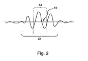
- Fig. 2 is a diagram schematically showing a bone surface section of the echo signals.
- each echo signal includes a range 60 in which the echo signal has a large amplitude corresponding to the bone surface.
- the bone surface section is considered simply as a portion with a large amplitude, it is unclear as to which portion in the range 60 corresponds to the surface section and, as a result, there is an error of approximately the range 60.
- a zero-cross point 62 is detected as a representative of each echo signal and the detected zero-cross point 62 is tracked to significantly increase the precision of the bone surface position.
- the zero-cross point 62 is detected as a time, within a tracking gate period 64, at which the polarity of the echo signal is inverted from positive to negative or from negative to positive.
- the time at which the polarity of the echo signal is inverted from positive to negative is the zero-cross point 62.
- a new tracking gate is set with the detected zero-cross point 62 as its center.
- a zero-cross point 62 is detected within the newly set tracking gate period 64. In this manner, a zero-cross point 62 is tracked as the bone surface point for each echo signal.
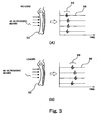
- Fig. 3 is a diagram for explaining tracking of a bone surface section by 4 echo signals.
- a shape of the bone is compared between a state in which no load is applied to the bone (no-load state) and a state in which a load is applied (loaded state).
- Fig. 3 shows tracking in each of the no-load state and the loaded state.
- Fig. 3 (A) shows tracking with respect to the bone 52 in the no-load state.
- Echo signals 68 corresponding to 4 ultrasonic beams 40 applied toward the bone 52 indicate a large amplitude (an amplitude maximum portion 69) at a section corresponding to the bone surface. It is possible to know the shape of the bone surface based on the position of the amplitude maximum portion 69 in each echo signal 68 (obtained time of the waveform). Because the zero-cross point (reference numeral 62 in Fig. 2) is detected as a surface point within the amplitude maximum portion 69, the position of the bone surface is very precisely identified.
- Fig. 3 (B) shows tracking with respect to the bone 52 in the loaded state. Similar to Fig. 3 (A), the shape of the bone surface can be known based on the echo signals 68 corresponding to the 4 ultrasonic beams 40. Because a load is applied, strain (bending of bone) of the bone 52 in Fig. 3 (B) is larger than that in Fig. 3 (A). Although an example configuration with 4 tracking echo signals is shown in Fig. 3, it is also possible to measure with a plurality of tracking echo signals, the number being different from 4.
- a surface point which is tracked for each echo signal, that is, for each ultrasonic beam 40 in the echo tracking processor unit 20 is the tracking point 42.
- An interpolation line generator unit 22 generates an interpolation line connecting these tracking points 42. That is, by interpolating with a curve among a plurality of tracking points 42 using a spline interpolation or a least square interpolation, an interpolation line is calculated. By increasing the number of echo signals for echo tracking process it is possible to more precisely approximate the surface shape of the bone by the interpolation line.
- an interpolation line is calculated considering the specific section. For example, when there is a fracture in the bone, it is possible to form interpolation lines for the portions of the bone separated by the bone fracture and to combine these two interpolation lines to form an interpolation line for the bone as a whole.
- the interpolation line is calculated for each time phase and is output to a memory 24, a translational displacement corrector unit 26, and a display image formation unit 32.
- the translational displacement corrector unit 26 cancels a translational displacement component between an interpolation line corresponding to a time phase in the no-load state stored in the memory 24 and an interpolation line corresponding to a time phase in the loaded state output from the interpolation line generator unit 22.
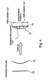
- Fig. 4 is a diagram for explaining a cancel operation of the translational displacement component in the translational displacement corrector unit 26.
- the translational displacement corrector unit 26 overlaps the interpolation line corresponding to the no-load state (no-load-state interpolation line 70) and the interpolation line corresponding to the loaded state (loaded-state interpolation line 72) on each other to cancel the translational displacement component.
- the overlapping of the interpolation lines is performed, for example, by matching the ends of the no-load-state interpolation line 70 and the loaded-state interpolation line 72.
- an amount of strain of the bone is very precisely extracted from a difference between the no-load-state interpolation line 70 and the loaded-state interpolation line 72 which are overlapped.
- a strain calculator unit 28 calculates an amount ⁇ of strain of the bone and outputs to a characteristic curve generator unit 30.
- the characteristic curve generator unit 30 generates a characteristic curve regarding the strain of the bone based on a load value output by a load measurement device 36 and an amount of strain of bone output by the strain calculator unit 28.
- Fig. 5 is a diagram showing a method for diagnosing the tibia using the ultrasonic diagnostic apparatus of Fig. 1.
- a weight 92 is placed on the lap of a subject 90 who is sitting on a chair so that a load due to the weight 92 is applied to the tibia.
- the load value due to the weight 92 is measured by the load measurement device 36 and is output to a main system 100 of the ultrasonic diagnosis device.
- the probe 10 is fixed by a probe fixer which is not shown and transmits and receives ultrasound to and from the crus (a site of the tibia).
- a positional relationship among the probe 10, crus, and probe fixer is shown in Fig. 6.
- the probe 10 is supported by a position adjuster device 102 which functions as a probe fixer and placed in a predetermined position.
- a load due to the weight 92 is applied to the crus 94 of the subject and the load value is measured by the load measurement device 36.
- a standoff 106 is mounted on the crus 94 with a belt 104.
- the standoff 106 is a gel-like medium which allows ultrasound to transmit through and has an acoustic impedance which is close to that of a living body.
- the probe 10 is placed in contact with the standoff 106 and transmits and receives ultrasound to and from the crus 94 of the subject via the standoff 106, to evaluate the mechanical characteristics of the tibia or fibula.
- Figs. 7 and 8 show other examples of methods for fixing the probe 10.
- the probe 10 is placed in contact with the crus 94 using the belt 104.
- the subject places the crus 94 in a water tank 112 and the probe 10 is fixed by an angle adjuster device 108 mounted on the water tank 112.
- the probe 10 is covered by a thin film rubber sheet window 110 and transmits and receives ultrasound to and from the crus 94 via water.
- a fixing device which is not shown is provided so that the position of the crus 94 with respect to the probe 10 does not change.
- the load value due to the weight 92 is measured by a load measurement device 36.
- Figs. 9 and 10 show examples of characteristic curves generated by the characteristic curve generator unit 30.
- Fig. 9 is a diagram showing each of a load value and an amount of strain of bone with the horizontal axis taken as an event (four stages of A, B, C, and D). It can be seen that, when the load value is increased stepwise in the order of events A, B, C, and D, the amount of strain of bone correspondingly increases in a stepwise manner.
- Fig. 10 is a diagram showing a relationship between the amount of strain of bone and the load value shown in Fig. 9, with the horizontal axis representing the amount of strain of bone and the vertical axis representing the load value.
- Fig. 10 also shows an approximation line calculated with data discretely obtained in the four stages of A, B, C, and D.
- the characteristic curves shown in Figs. 9 and 10 are displayed on a display (reference numeral 34 of Fig. 1) through a display image formation unit (reference numeral 32 of Fig. 1).
- a mechanical characteristic of bone for example, it is possible to quantify (load)/(strain) which is a slope of the approximation line in Fig. 10, as a measure of the rigidity of the bone. For example, when an average value for healthy subjects is A and the value for the patient is B, it is determined that the rigidity of the bone of the diagnosis target (subject) is normal when the value of B is within a predetermined range estimated from the value of A and that the rigidity of the bone of the diagnosis target is abnormal when the value of B is outside the range. It is also possible to evaluate the rigidity of the bone from a difference, (B - A).
- a weight load which is an external action to the bone and quantifying plastic deformation of the bone after the weight is removed.
- Other methods for applying a load to the tibia include standing on one foot, standing on both feet, and cycle load by walking.
- the load value can be measured by the load measurement device (reference numeral 36 in Fig. 1) similar to the above-described configuration.
- Figs. 11 and 12 show examples of characteristic curves generated by the characteristic curve generator unit 30 in the case of a cycle load.
- Fig. 11 is a characteristic curve showing each of the load value and amount of strain of the bone with the horizontal axis representing time.
- Fig. 11 shows that when the load value is gradually increased from time 0 to time t, the amount of strain correspondingly gradually increases from time 0 to time t. It can also be seen that when the load value is gradually reduced after time t, the amount of strain is also gradually reduced.
- the characteristic curve of Fig. 11 is displayed on a display (reference numeral 34 in Fig. 1) through a display image formation unit (reference numeral 32 in Fig. 1). The examiner can read the amount of strain of the bone corresponding to a load value from the characteristic curve displayed on the display 34.
- Fig. 12 shows a characteristic curve in which the horizontal axis represents an amount of strain of the bone and the vertical axis represents a load value. There is a hysteresis characteristic between the amount of load to the bone and the amount of strain of the bone. In other words, an increase characteristic of the amount of strain of the bone when the load value is gradually increased to the maximum load value and a decrease characteristic of the amount of strain of the bone when the load is gradually reduced from the maximum load value would not be the same curve.
- Fig. 12 shows a characteristic when the load value is increased to a maximum load value and then reduced from the maximum load value. The area of a region 80 reflects the hysteresis characteristic between the load value and the amount of strain.
- the characteristic curve shown in Fig. 12 is displayed on the display (reference numeral 34 of Fig. 1) through the display image formation unit (reference numeral 32 of Fig. 1).
- the display image formation unit 32 forms a display image based on the cross sectional image of the bone formed in the cross sectional image formation unit 18 and the characteristic curve generated by the characteristic curve generator unit 30 and displays the formed image on the display 34.
- the cross sectional image and the characteristic curve are, for example, switched and displayed based on an instruction by the examiner.
- the cross sectional image and the characteristic curve may besimultaneously displayed.
- the mechanical characteristic thus obtained such as the amount of strain or strength of bone is an important measure of a quantitative evaluation of bone union and significantly contributes as objective and reliable base data of diagnosis in judgment of effects by an agent to an increase in the bone strength, removal of a fixator/implant, and instruction of degree of load to a patient.
- the diagnosis target bone of the ultrasonic diagnostic apparatus is not limited to the tibia and the fibula, and may alternatively applied to, for example, femur and armbones.
- a diagnosis target wrapping around a weight and diagnose with the probe contacting the femur, to measure the load value applied to the femur and the shape of the femur.
- the arm bones it is possible to contact the probe on the arm of the subject and to diagnose while the arm is loaded by the subject pushing, with the arm, a load measurement device mounted on a wall.
- the ultrasonic diagnostic apparatus of the present invention can be applied to the bones of various regions in the subject.
- a diagnosis using the ultrasonic diagnostic apparatus of the present invention is advantageous in that the diagnosis can be applied independent of the method of treatment of bone fracture.
- the ultrasonic diagnostic apparatus of the present invention it is possible to non-invasively and quantitatively evaluate a mechanical characteristic of the bone within a living body.
Landscapes
- Health & Medical Sciences (AREA)
- Life Sciences & Earth Sciences (AREA)
- Biomedical Technology (AREA)
- Heart & Thoracic Surgery (AREA)
- Rheumatology (AREA)
- Biophysics (AREA)
- Nuclear Medicine, Radiotherapy & Molecular Imaging (AREA)
- Pathology (AREA)
- Radiology & Medical Imaging (AREA)
- Engineering & Computer Science (AREA)
- Orthopedic Medicine & Surgery (AREA)
- Physics & Mathematics (AREA)
- Medical Informatics (AREA)
- Molecular Biology (AREA)
- Surgery (AREA)
- Animal Behavior & Ethology (AREA)
- General Health & Medical Sciences (AREA)
- Public Health (AREA)
- Veterinary Medicine (AREA)
- Ultra Sonic Daignosis Equipment (AREA)
Claims (16)
- Appareil de diagnostic à ultrasons comprenant :une unité d'émission-réception (12) qui génère une pluralité de faisceaux d'ultrasons concernant un os (52) chez un sujet (50) et reçoit une pluralité de signaux d'écho correspondant aux faisceaux d'ultrasons ; etune unité de mesure de forme qui identifie un point de surface correspondant à une surface de l'os pour chacun des signaux d'écho et qui génère des données de forme de la surface de l'os à partir de la pluralité de points de surface obtenus de la pluralité de signaux d'écho,
caractérisé parune unité d'évaluation de caractéristique qui évalue une caractéristique mécanique de l'os à partir d'une modification des données de forme lorsqu'une action extérieure est appliquée sur l'os. - Appareil de diagnostic à ultrasons selon la revendication 1, dans lequel
l'unité d'émission-réception (12) génère les faisceaux d'ultrasons dans une même section transversale de l'os (52) chez le sujet (50). - Appareil de diagnostic à ultrasons selon la revendication 2, dans lequel
l'unité de mesure de forme comprend une unité de suivi qui suit les points de surface depui un état dans lequel l'action extérieure n'est pas appliquée, jusqu'à un état dans lequel l'action extérieure est appliquée. - Appareil de diagnostic à ultrasons selon la revendication 3, dans lequel
l'unité de mesure de forme comprend une unité génératrice de données de forme qui génère les données de forme pour chaque phase temporelle dans l'état dans lequel l'action extérieure n'est pas appliquée et dans l'état dans lequel l'action extérieure est appliquée. - Appareil de diagnostic à ultrasons selon la revendication 4, dans lequel
l'unité génératrice de données de forme génère, comme données de forme, une ligne d'interpolation reliant la pluralité de points de surface pour chaque phase temporelle. - Appareil de diagnostic à ultrasons selon la revendication 5, dans lequel
l'unité d'évaluation de caractéristiques superpose la ligne d'interpolation correspondant à l'état dans lequel l'action extérieure n'est pas appliquée et la ligne d'interpolation correspondant à l'état dans lequel l'action extérieure est appliquée en superposant l'une des lignes d'interpolation sur l'autre afin de corriger un déplacement dû à un mouvement de l'os entre les deux lignes d'interpolation et évalue la caractéristique mécanique de l'os à partir des deux lignes d'interpolation corrigées. - Appareil de diagnostic à ultrasons comprenant :une unité d'émission-réception (12) qui génère une pluralité de faisceaux d'ultrasons concernant un os (52) chez un sujet (50) et reçoit une pluralité de signaux d'écho correspondant aux faisceaux d'ultrasons ; etune unité de suivi qui identifie un point de surface correspondant à une surface de l'os pour chacun des signaux d'écho et qui suit les points de surface à partir d'un état hors charge dans lequel aucune charge n'est appliquée sur l'os, et jusqu'à un état sous charge dans lequel une charge est appliquée sur l'os,
caractérisé parune unité (22) génératrice de lignes d'interpolation qui génère une ligne d'interpolation reliant une pluralité des points de surface pour chaque phase temporelle dans l'état hors charge et dans l'état sous charge,une unité (26) correctrice de déplacement de translation qui translate l'une de la ligne d'interpolation correspondant à l'état hors charge et de la ligne d'interpolation correspondant à l'état sous charge de telle manière que l'une des lignes d'interpolation se trouve au-dessus de l'autre ligne d'interpolation, et corrige une composante de déplacement par translation entre les deux lignes d'interpolation, etune unité (28) de calcul de déformation qui calcule une quantité de déformation de l'os dans l'état sous charge à partir des deux lignes d'interpolation, dans laquelle la composante de déplacement par translation est corrigée. - Appareil de diagnostic à ultrasons selon la revendication 7, dans lequel
l'unité de suivi détecte un point de passage par zéro comme point de surface et suit le point de passage par zéro détecté. - Appareil de diagnostic à ultrasons selon la revendication 8, dans lequel
le point de passage par zéro est détecté à un instant auquel une polarité du signal d'écho est inversée de positif à négatif ou de négatif à positif dans une période de porte de suivi. - Appareil de diagnostic à ultrasons selon la revendication 7, dans lequel
l'unité (22) génératrice de lignes d'interpolation génère une ligne d'interpolation à l'aide d'une interpolation par splines. - Appareil de diagnostic à ultrasons selon la revendication 7, dans lequel
l'unité (22) génératrice de lignes d'interpolation génère une ligne d'interpolation à l'aide d'une interpolation par la méthode des moindres carrés. - Appareil de diagnostic à ultrasons selon la revendication 7, comprenant de plus :une unité (30) génératrice de courbe caractéristique qui génère une courbe caractéristique indiquant une relation entre la valeur de la charge et le taux de déformation de l'os dans l'état sous charge.
- Appareil de diagnostic à ultrasons selon la revendication 12, dans lequel l'unité (30) génératrice de courbe caractéristique génère une courbe caractéristique dans laquelle un axe représente le temps et un autre axe représente la valeur de la charge.
- Appareil de diagnostic à ultrasons selon la revendication 12, dans lequel l'unité (30) génératrice de courbe caractéristique génère une courbe caractéristique dans laquelle un axe représente le temps et un autre axe représente le taux de déformation de l'os.
- Appareil de diagnostic à ultrasons selon la revendication 12, dans lequel l'unité (30) génératrice de courbe caractéristique génère une courbe caractéristique dans laquelle un axe représente le taux de déformation de l'os et un autre axe représente la valeur de la charge.
- Appareil de diagnostic à ultrasons selon la revendication 12, comprenant de plus :une unité d'affichage (34) qui affiche une image de la section transversale de l'os à partir de la pluralité de signaux d'écho, dans lequel l'unité d'affichage (34) affiche la ligne d'interpolation dans une position appropriée sur l'image de section transversale de l'os (52).
Priority Applications (2)
| Application Number | Priority Date | Filing Date | Title |
|---|---|---|---|
| DE200460010122 DE602004010122T2 (de) | 2004-09-24 | 2004-09-24 | Ultraschall-Diagnosegerät |
| EP20040022856 EP1639946B1 (fr) | 2004-09-24 | 2004-09-24 | Dispositif de diagnostic ultrasonore |
Applications Claiming Priority (1)
| Application Number | Priority Date | Filing Date | Title |
|---|---|---|---|
| EP20040022856 EP1639946B1 (fr) | 2004-09-24 | 2004-09-24 | Dispositif de diagnostic ultrasonore |
Publications (2)
| Publication Number | Publication Date |
|---|---|
| EP1639946A1 EP1639946A1 (fr) | 2006-03-29 |
| EP1639946B1 true EP1639946B1 (fr) | 2007-11-14 |
Family
ID=34926711
Family Applications (1)
| Application Number | Title | Priority Date | Filing Date |
|---|---|---|---|
| EP20040022856 Active EP1639946B1 (fr) | 2004-09-24 | 2004-09-24 | Dispositif de diagnostic ultrasonore |
Country Status (2)
| Country | Link |
|---|---|
| EP (1) | EP1639946B1 (fr) |
| DE (1) | DE602004010122T2 (fr) |
Families Citing this family (4)
| Publication number | Priority date | Publication date | Assignee | Title |
|---|---|---|---|---|
| JP4854212B2 (ja) * | 2005-03-31 | 2012-01-18 | 日立アロカメディカル株式会社 | 超音波診断装置 |
| DE602007004976D1 (de) | 2007-07-27 | 2010-04-08 | Aloka Co Ltd | Diagnostisches Ultraschallgerät |
| US8187185B2 (en) | 2007-08-08 | 2012-05-29 | Hitachi Aloka Medical, Ltd. | Ultrasound diagnostic apparatus |
| DE102010053449B4 (de) * | 2010-12-06 | 2013-04-18 | Wittenstein Ag | Vorrichtung zur Bestimmung von Knochenzuständen und Verfahren zum Betrieb der Vorrichtung |
Family Cites Families (5)
| Publication number | Priority date | Publication date | Assignee | Title |
|---|---|---|---|---|
| KR920702968A (ko) * | 1989-10-24 | 1992-12-17 | 브라이언 레슬리 코니쉬 | 뼈의 진동분석방법과 장치 |
| US5474070A (en) * | 1989-11-17 | 1995-12-12 | The Board Of Regents Of The University Of Texas System | Method and apparatus for elastographic measurement and imaging |
| US5678565A (en) * | 1992-12-21 | 1997-10-21 | Artann Corporation | Ultrasonic elasticity imaging method and device |
| JP2883290B2 (ja) * | 1995-04-10 | 1999-04-19 | アロカ株式会社 | 超音波骨評価装置 |
| CA2333224A1 (fr) * | 2001-01-31 | 2002-07-31 | University Technologies International Inc. | Methode diagnostique et appareil non-effractifs pour le systdme musculo-squelettique |
-
2004
- 2004-09-24 EP EP20040022856 patent/EP1639946B1/fr active Active
- 2004-09-24 DE DE200460010122 patent/DE602004010122T2/de active Active
Also Published As
| Publication number | Publication date |
|---|---|
| DE602004010122D1 (de) | 2007-12-27 |
| EP1639946A1 (fr) | 2006-03-29 |
| DE602004010122T2 (de) | 2008-09-11 |
Similar Documents
| Publication | Publication Date | Title |
|---|---|---|
| US7806823B2 (en) | Ultrasonic diagnostic apparatus | |
| EP1707124B1 (fr) | Dispositif de diagnostic à ultrasons de maladies osseuses | |
| US7938778B2 (en) | Ultrasound diagnosis apparatus | |
| JP3954981B2 (ja) | 超音波診断装置 | |
| US8419643B2 (en) | Ultrasonic method and apparatus for assessment of bone | |
| US20090069683A1 (en) | Ultrasound diagnosis apparatus | |
| US6086538A (en) | Methods and apparatus for evaluation of bone condition | |
| US8727986B2 (en) | Method and apparatus for assessing risk of preterm delivery | |
| JP4153407B2 (ja) | 超音波診断装置 | |
| US7727152B2 (en) | Method and apparatus for scanning confocal acoustic diagnostic for bone quality | |
| JP4381118B2 (ja) | 超音波診断装置 | |
| US20090112094A1 (en) | Phased Apply Ultrasound With Electronically Controlled Focal Point For Assessing Bone Quality Via Acoustic Topology And Wave Transmit Functions | |
| EP1639946B1 (fr) | Dispositif de diagnostic ultrasonore | |
| US11490876B2 (en) | Ultrasonic diagnostic device and method for evaluating physical properties of biological tissue | |
| JP4716792B2 (ja) | 超音波診断装置 | |
| US9307951B2 (en) | Ultrasound diagnosis apparatus | |
| JP4608458B2 (ja) | 超音波診断装置 | |
| JP4627686B2 (ja) | 超音波診断装置 | |
| JP4517090B2 (ja) | 超音波診断装置 | |
| JP2664628B2 (ja) | 踵骨を対象とする骨評価装置 | |
| Harada et al. | 2A-1 A New Method for Measuring Bone Strength using Echo-Tracking | |
| JP2005095221A (ja) | 超音波骨計測装置及び骨計測方法 | |
| Sakai et al. | 12C-4 A Minute Bone Bending Angle Measuring Method Using Echo-Tracking for Assessment of Bone Strength | |
| Laugier et al. | Ultrasound parametric imaging of bone in vivo |
Legal Events
| Date | Code | Title | Description |
|---|---|---|---|
| PUAI | Public reference made under article 153(3) epc to a published international application that has entered the european phase |
Free format text: ORIGINAL CODE: 0009012 |
|
| 17P | Request for examination filed |
Effective date: 20050315 |
|
| AK | Designated contracting states |
Kind code of ref document: A1 Designated state(s): AT BE BG CH CY CZ DE DK EE ES FI FR GB GR HU IE IT LI LU MC NL PL PT RO SE SI SK TR |
|
| AX | Request for extension of the european patent |
Extension state: AL HR LT LV MK |
|
| GRAP | Despatch of communication of intention to grant a patent |
Free format text: ORIGINAL CODE: EPIDOSNIGR1 |
|
| GRAS | Grant fee paid |
Free format text: ORIGINAL CODE: EPIDOSNIGR3 |
|
| AKX | Designation fees paid |
Designated state(s): CH DE FR GB IT LI |
|
| GRAA | (expected) grant |
Free format text: ORIGINAL CODE: 0009210 |
|
| AK | Designated contracting states |
Kind code of ref document: B1 Designated state(s): CH DE FR GB IT LI |
|
| REG | Reference to a national code |
Ref country code: GB Ref legal event code: FG4D |
|
| REG | Reference to a national code |
Ref country code: CH Ref legal event code: EP |
|
| REF | Corresponds to: |
Ref document number: 602004010122 Country of ref document: DE Date of ref document: 20071227 Kind code of ref document: P |
|
| REG | Reference to a national code |
Ref country code: CH Ref legal event code: NV Representative=s name: BOGENSBERGER PATENT- & MARKENBUERO DR. BURKHARD BO |
|
| REG | Reference to a national code |
Ref country code: CH Ref legal event code: PFA Owner name: ALOKA CO. LTD. Free format text: ALOKA CO. LTD.#6-22-1 MURE#MITAKA-SHI TOKYO, 181-8622 (JP) $ NAKAMURA, KOZO#2-23-13, KITA-MACHI, NERIMA-KU#TOKYO, 179-0081 (JP) $ OHNISHI, ISAO#3-18-22, ASAGAYAKITA, SUGINAMI-KU#TOKYO 166-0001 (JP) -TRANSFER TO- ALOKA CO. LTD.#6-22-1 MURE#MITAKA-SHI TOKYO, 181-8622 (JP) $ NAKAMURA, KOZO#2-23-13, KITA-MACHI, NERIMA-KU#TOKYO, 179-0081 (JP) $ OHNISHI, ISAO#3-18-22, ASAGAYAKITA, SUGINAMI-KU#TOKYO 166-0001 (JP) |
|
| ET | Fr: translation filed | ||
| PLBE | No opposition filed within time limit |
Free format text: ORIGINAL CODE: 0009261 |
|
| STAA | Information on the status of an ep patent application or granted ep patent |
Free format text: STATUS: NO OPPOSITION FILED WITHIN TIME LIMIT |
|
| 26N | No opposition filed |
Effective date: 20080815 |
|
| REG | Reference to a national code |
Ref country code: CH Ref legal event code: PFA Owner name: NAKAMURA, KOZO Free format text: ALOKA CO. LTD.#6-22-1 MURE#MITAKA-SHI TOKYO, 181-8622 (JP) $ NAKAMURA, KOZO#2-23-13, KITA-MACHI, NERIMA-KU#TOKYO, 179-0081 (JP) $ OHNISHI, ISAO#3-18-22, ASAGAYAKITA, SUGINAMI-KU#TOKYO 166-0001 (JP) -TRANSFER TO- NAKAMURA, KOZO#2-23-13, KITA-MACHI, NERIMA-KU#TOKYO, 179-0081 (JP) $ OHNISHI, ISAO#3-18-22, ASAGAYAKITA, SUGINAMI-KU#TOKYO 166-0001 (JP) $ HITACHI ALOKA MEDICAL, LTD.#6-22-1 MURE, MITAKA-SHI#181-8622 TOKYO (JP) |
|
| REG | Reference to a national code |
Ref country code: FR Ref legal event code: CD |
|
| REG | Reference to a national code |
Ref country code: DE Ref legal event code: R081 Ref document number: 602004010122 Country of ref document: DE Owner name: NAKAMURA, KOZO, JP Free format text: FORMER OWNER: ALOKA CO. LTD.,KOZO NAKAMURA,ISAO OHNISHI, , JP Effective date: 20110826 Ref country code: DE Ref legal event code: R081 Ref document number: 602004010122 Country of ref document: DE Owner name: HITACHI LTD, JP Free format text: FORMER OWNERS: ALOKA CO. LTD., MITAKA, TOKIO/TOKYO, JP; NAKAMURA, KOZO, TOKYO, JP; OHNISHI, ISAO, TOKYO, JP Effective date: 20110826 Ref country code: DE Ref legal event code: R081 Ref document number: 602004010122 Country of ref document: DE Owner name: HITACHI ALOKA MEDICAL, LTD., JP Free format text: FORMER OWNER: ALOKA CO. LTD.,KOZO NAKAMURA,ISAO OHNISHI, , JP Effective date: 20110826 Ref country code: DE Ref legal event code: R081 Ref document number: 602004010122 Country of ref document: DE Owner name: OHNISHI, ISAO, JP Free format text: FORMER OWNER: ALOKA CO. LTD.,KOZO NAKAMURA,ISAO OHNISHI, , JP Effective date: 20110826 Ref country code: DE Ref legal event code: R082 Ref document number: 602004010122 Country of ref document: DE Representative=s name: WEBER & HEIM PATENTANWAELTE, DE Effective date: 20110826 Ref country code: DE Ref legal event code: R081 Ref document number: 602004010122 Country of ref document: DE Owner name: OHNISHI, ISAO, JP Free format text: FORMER OWNERS: ALOKA CO. LTD., MITAKA, TOKIO/TOKYO, JP; NAKAMURA, KOZO, TOKYO, JP; OHNISHI, ISAO, TOKYO, JP Effective date: 20110826 Ref country code: DE Ref legal event code: R081 Ref document number: 602004010122 Country of ref document: DE Owner name: HITACHI ALOKA MEDICAL, LTD., JP Free format text: FORMER OWNERS: ALOKA CO. LTD., MITAKA, TOKIO/TOKYO, JP; NAKAMURA, KOZO, TOKYO, JP; OHNISHI, ISAO, TOKYO, JP Effective date: 20110826 Ref country code: DE Ref legal event code: R082 Ref document number: 602004010122 Country of ref document: DE Representative=s name: WEBER & HEIM PATENTANWAELTE PARTNERSCHAFTSGESE, DE Effective date: 20110826 Ref country code: DE Ref legal event code: R081 Ref document number: 602004010122 Country of ref document: DE Owner name: NAKAMURA, KOZO, JP Free format text: FORMER OWNERS: ALOKA CO. LTD., MITAKA, TOKIO/TOKYO, JP; NAKAMURA, KOZO, TOKYO, JP; OHNISHI, ISAO, TOKYO, JP Effective date: 20110826 Ref country code: DE Ref legal event code: R082 Ref document number: 602004010122 Country of ref document: DE Representative=s name: WUNDERLICH & HEIM PATENTANWAELTE PARTNERSCHAFT, DE Effective date: 20110826 |
|
| REG | Reference to a national code |
Ref country code: CH Ref legal event code: PCAR Free format text: NEW ADDRESS: FALLSGASSE 7, 9492 ESCHEN (LI) |
|
| REG | Reference to a national code |
Ref country code: FR Ref legal event code: PLFP Year of fee payment: 13 |
|
| REG | Reference to a national code |
Ref country code: DE Ref legal event code: R081 Ref document number: 602004010122 Country of ref document: DE Owner name: FUJIFILM HEALTHCARE CORPORATION, KASHIWA-SHI, JP Free format text: FORMER OWNERS: HITACHI ALOKA MEDICAL, LTD., TOKIO/TOKYO, JP; NAKAMURA, KOZO, TOKYO, JP; OHNISHI, ISAO, TOKYO, JP Ref country code: DE Ref legal event code: R082 Ref document number: 602004010122 Country of ref document: DE Representative=s name: WEBER & HEIM PATENTANWAELTE PARTNERSCHAFTSGESE, DE Ref country code: DE Ref legal event code: R081 Ref document number: 602004010122 Country of ref document: DE Owner name: HITACHI LTD, JP Free format text: FORMER OWNERS: HITACHI ALOKA MEDICAL, LTD., TOKIO/TOKYO, JP; NAKAMURA, KOZO, TOKYO, JP; OHNISHI, ISAO, TOKYO, JP Ref country code: DE Ref legal event code: R082 Ref document number: 602004010122 Country of ref document: DE Representative=s name: WUNDERLICH & HEIM PATENTANWAELTE PARTNERSCHAFT, DE |
|
| REG | Reference to a national code |
Ref country code: GB Ref legal event code: 732E Free format text: REGISTERED BETWEEN 20170504 AND 20170510 Ref country code: CH Ref legal event code: NV Representative=s name: SCHNEIDER FELDMANN AG PATENT- UND MARKENANWAEL, CH Ref country code: CH Ref legal event code: PUEA Owner name: HITACHI, LTD., JP Free format text: FORMER OWNER: NAKAMURA, KOZO, JP |
|
| REG | Reference to a national code |
Ref country code: FR Ref legal event code: PLFP Year of fee payment: 14 |
|
| REG | Reference to a national code |
Ref country code: FR Ref legal event code: TQ Owner name: HITACHI, LTD., JP Effective date: 20170818 Ref country code: FR Ref legal event code: TQ Owner name: NAKAMURA, KOZO, JP Effective date: 20170818 Ref country code: FR Ref legal event code: TQ Owner name: OHNISHI, ISAO, JP Effective date: 20170818 |
|
| REG | Reference to a national code |
Ref country code: DE Ref legal event code: R082 Ref document number: 602004010122 Country of ref document: DE Representative=s name: WUNDERLICH & HEIM PATENTANWAELTE PARTNERSCHAFT, DE |
|
| REG | Reference to a national code |
Ref country code: FR Ref legal event code: PLFP Year of fee payment: 15 |
|
| REG | Reference to a national code |
Ref country code: CH Ref legal event code: PFA Owner name: HITACHI, LTD., JP Free format text: FORMER OWNER: HITACHI, LTD., JP |
|
| REG | Reference to a national code |
Ref country code: DE Ref legal event code: R081 Ref document number: 602004010122 Country of ref document: DE Owner name: FUJIFILM HEALTHCARE CORPORATION, KASHIWA-SHI, JP Free format text: FORMER OWNER: HITACHI LTD, TOKYO, JP |
|
| REG | Reference to a national code |
Ref country code: GB Ref legal event code: 732E Free format text: REGISTERED BETWEEN 20220303 AND 20220309 |
|
| P01 | Opt-out of the competence of the unified patent court (upc) registered |
Effective date: 20230522 |
|
| PGFP | Annual fee paid to national office [announced via postgrant information from national office to epo] |
Ref country code: IT Payment date: 20230810 Year of fee payment: 20 Ref country code: GB Payment date: 20230803 Year of fee payment: 20 |
|
| PGFP | Annual fee paid to national office [announced via postgrant information from national office to epo] |
Ref country code: FR Payment date: 20230808 Year of fee payment: 20 Ref country code: DE Payment date: 20230802 Year of fee payment: 20 |
|
| PGFP | Annual fee paid to national office [announced via postgrant information from national office to epo] |
Ref country code: CH Payment date: 20231001 Year of fee payment: 20 |