EP1639712B1 - Method and system for coded null packet-aided synchronization - Google Patents
Method and system for coded null packet-aided synchronization Download PDFInfo
- Publication number
- EP1639712B1 EP1639712B1 EP04756366.3A EP04756366A EP1639712B1 EP 1639712 B1 EP1639712 B1 EP 1639712B1 EP 04756366 A EP04756366 A EP 04756366A EP 1639712 B1 EP1639712 B1 EP 1639712B1
- Authority
- EP
- European Patent Office
- Prior art keywords
- data
- communication system
- time slots
- communication
- set forth
- Prior art date
- Legal status (The legal status is an assumption and is not a legal conclusion. Google has not performed a legal analysis and makes no representation as to the accuracy of the status listed.)
- Expired - Lifetime
Links
- 238000000034 method Methods 0.000 title claims description 16
- 238000004891 communication Methods 0.000 claims description 75
- 230000005540 biological transmission Effects 0.000 claims description 21
- 238000012937 correction Methods 0.000 claims description 9
- 238000001228 spectrum Methods 0.000 claims description 4
- 238000010586 diagram Methods 0.000 description 7
- 230000000875 corresponding effect Effects 0.000 description 4
- 238000001514 detection method Methods 0.000 description 3
- 230000003595 spectral effect Effects 0.000 description 3
- 230000002596 correlated effect Effects 0.000 description 2
- 238000013461 design Methods 0.000 description 2
- 238000011161 development Methods 0.000 description 2
- 238000004519 manufacturing process Methods 0.000 description 2
- 238000012986 modification Methods 0.000 description 2
- 230000004048 modification Effects 0.000 description 2
- 238000012545 processing Methods 0.000 description 2
- 230000011664 signaling Effects 0.000 description 2
- 230000001413 cellular effect Effects 0.000 description 1
- 238000005516 engineering process Methods 0.000 description 1
- 238000001914 filtration Methods 0.000 description 1
- 238000013507 mapping Methods 0.000 description 1
- 238000013519 translation Methods 0.000 description 1
Images
Classifications
-
- H—ELECTRICITY
- H04—ELECTRIC COMMUNICATION TECHNIQUE
- H04B—TRANSMISSION
- H04B7/00—Radio transmission systems, i.e. using radiation field
- H04B7/14—Relay systems
- H04B7/15—Active relay systems
- H04B7/204—Multiple access
- H04B7/212—Time-division multiple access [TDMA]
-
- H—ELECTRICITY
- H04—ELECTRIC COMMUNICATION TECHNIQUE
- H04L—TRANSMISSION OF DIGITAL INFORMATION, e.g. TELEGRAPHIC COMMUNICATION
- H04L7/00—Arrangements for synchronising receiver with transmitter
- H04L7/04—Speed or phase control by synchronisation signals
- H04L7/041—Speed or phase control by synchronisation signals using special codes as synchronising signal
-
- H—ELECTRICITY
- H04—ELECTRIC COMMUNICATION TECHNIQUE
- H04J—MULTIPLEX COMMUNICATION
- H04J13/00—Code division multiplex systems
-
- H—ELECTRICITY
- H04—ELECTRIC COMMUNICATION TECHNIQUE
- H04W—WIRELESS COMMUNICATION NETWORKS
- H04W74/00—Wireless channel access
- H04W74/04—Scheduled access
Definitions
- the present invention relates to improving time division multiple access (TDMA) synchronization in a direct sequence spread spectrum communication (DSSS) system.
- TDMA time division multiple access
- DSSS direct sequence spread spectrum communication
- a base unit facilitates communication between other base units and multiple local mobile terminals (MTs), which may also be referred to as handsets.
- the base unit and the mobile terminals are typically capable of transmitting and receiving a data signal at a particular frequency or group of frequencies.
- the data signal is broken into a number of smaller increments known as time slots, which may recur during each cycle of the data signal.
- time slots time slots
- multiple data transmission sessions can take place simultaneously.
- a mobile terminal may be assigned a particular time slot. The data from that mobile terminal may be transmitted in the assigned time slot for the duration of a communication session.
- GB 2322043 A published on August 12, 1998 discloses a method for allocating a traffic channel in a TDMA communication system.
- EP 0 853 400 A published on July 15, 1998 discloses a radio transmission method for digital multimedia signals between subscriber stations in a local network operating with a mixed frequency and time division multiplex method FDMA/TDMA.
- WO 98/25356 A1 published on June 11, 1998 discloses a method for distinguishing between control signalling and user data.
- TDMA may be used in spread spectrum communication systems, such as DSSS systems.
- a DSSS system the original data signal is spread by multiplying it with a wideband spreading code.
- Spreading converts a narrowband signal with a relatively high power spectral density into a wideband signal that has a low power spectral density. That is, the energy of the signal is spread out over a wide frequency range.
- a DSSS signal is often below the noise floor.
- a DSSS receiver is able to process the signal because of the correlation gain from correlating against the spreading code at the receiver. Because of their low power spectral density, DSSS signals are often hard to detect and cause very little interference with other signals in that frequency band.
- a typical method of synchronizing a TDMA structure that is being received is to decode the payload data contained in data packets associated with the various time slots to determine the reference point in the TDMA structure of the decoded packet.
- This scheme generally requires a receiving system to, first, reliably detect the packet boundaries and then to be able to demodulate, decode and otherwise process the packet to extract the relevant TDMA information.
- Such initial packet boundary detection may be difficult to perform, especially in conditions where signal-to-noise ration (SNR) SNR is low.
- SNR signal-to-noise ration
- An example of the typical method is to correlate the received data signals with an appropriate pseudo-noise (PN) sequence to determine the correlation peak locations.
- PN pseudo-noise
- packet boundaries may be locked onto and payload data decoded based on the location of the data relative to the identified packet boundary.
- FEC forward error correction
- An apparatus and method that allows a reliable determination of the TDMA structure of a data signal in the correlation domain without decoding the FEC-encoded payload data, thus speeding up the TDMA acquisition and improving its accuracy, is desirable.
- the disclosed embodiments relate to a communication system comprising a transmitter in accordance with claim 1.
- the receiver may associate logical values with the correlation peaks and decode the logical values to obtain the information about the TDMA structure of the communication system.
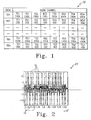
- FIG. 1 is a diagram showing an exemplary TDMA structure in accordance with embodiments of the present invention.
- the TDMA structure which illustrates the view of a TDMA base station, is generally referred to by the reference numeral 10.
- TD1 represents a command data transmission slot.
- RD1 represents a command data receive slot.
- the rows that begin with TD1 and RD1 together comprise a first horizontal slot.
- TS1, TS2, TS3 and TS4 each correspond to various odd and even transmission time slots.
- RS1, RS2, RS3 and RS 4 each correspond to various odd and even receive time slots.
- An nth horizontal slot is represented by the two rows that begin, respectively, with a command data transmission slot TDn and a command data receive slot RDn.
- one or more of the transmission slots TSn may be unused for purposes of transmitting communication data.
- the transmission slots may be unused because no mobile terminal is engaged in a communication session that requires the use of the time slot for communication data.
- the base station may insert fixed signature data in the form of null data packets into all unused time slots.
- null data means a pre-defined signature packet that is different from an information-bearing payload packet containing data transmitted on the TDMA slots already occupied.
- the expression "null" is not intended to imply an all-zero packet.
- Each time slot may be given its own predetermined identity pattern that is embedded in an otherwise unused time slot.
- the data may be determined by examining the correlation peaks before the data packet itself is decoded by a receiver.
- a mobile terminal desiring to establish the initial synchronization with the base station may correlate the received signals and determine immediately what kind of packet is being received and/or determine which time slot is available for transmission.
- the null packets sent by the base station may carry information indicating the identity of the associated time slots in the correlation domain.
- a mobile unit or handset desiring to establish a communication link can immediately find an available time slot without going through layers of protocol and decoding the payload data. Any handset that 'wakes up' from the sleep mode can quickly re-synchronize by matching the received correlation patterns and adjusting the timing and carrier offsets accordingly.
- FIG. 2 is a graph showing correlation domain data corresponding to the TDMA structure shown in FIG. 1 .
- the graph shown in FIG. 2 is generally referred to by the reference numeral 20.
- the x-axis of the graph 10 shows a range of correlation bin index values and the y-axis shows the amplitude of a received TDMA signal.
- a plurality of positive correlation peaks 22 correspond to various symbols transmitted in the transmission slots (TS) shown in FIG. 1 .
- a plurality of negative correlation peaks 24 also correspond to various symbols transmitted in the transmission slots (TS) shown in FIG. 1 .
- Three positive correlation peaks have been specifically identified with the reference numeral 22 and three negative correlation peaks have been identified with the reference numeral 24 in FIG. 2 for purposes of illustration. Those of ordinary skill in the art will appreciate that other correlation peaks having approximately the same positive amplitude as the correlation peaks 22 and the same negative amplitude as the correlation peaks 24 are illustrated in FIG. 2 .
- the pattern of the correlation peaks shown in FIG. 2 may embody useful information sufficient to allow any mobile unit or handset receiver to determine TDMA system parameters. Examples of data that may be coded into null packets to convey this information include whether the packet was sent by base station or a mobile unit, the identity of a time slot in which a packet is received (including the vertical slot number, horizontal slot number and whether the slot is odd or even), transmission power level, strong or weak forward error correction (FEC) or the like.
- FEC forward error correction
- eight (8) audio and one (1) command data slots require at least nine (9) patterns of correlation peaks.
- the correlation peaks shown in FIG. 2 may be assigned a logical value, such as a logical value of "0" or "1.”
- a negative peak bin can be mapped to logic 1 and positive peak bin can be mapped to logic 0, or vice versa.
- the correlation bins generated from payload data may be identical to the signature correlation bins.
- a possible solution may be to use redundancy in the signature patterns.
- the payload data is typically randomized and the repetition of strings of 0s or 1s for a long duration is rare.
- the repetition of 0s or 1s can be created on purpose to eliminate the possibility of having identical payload data generated pattern and signature pattern.
- An alternative way to achieve unambiguous detection may be to look for the correlation pattern to occur multiple (2 or more) times separated by a pre-defined number of packets. The probability of a payload pattern to repeatedly match one of the designated signature patterns should be insignificantly low.
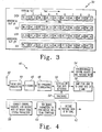
- FIG. 3 is a diagram showing an alternative exemplary TDMA data structure in accordance with embodiments of the present invention.
- the TDMA structure which illustrates the view of a TDMA base station, is generally referred to by the reference numeral 30.
- a first horizontal slot comprises odd and even rows.
- the even row includes a command data transmission slot BT_D1 and occupied data transmission slots BT_A1 and BT_A4. Also included in the even row are occupied data receive slots BR_A1 and BR_A4.
- Empty even data receive slots (shown in hatched lines) are identified as BR_S2 and BR_S3.
- empty even data transmission slots (shown in hatched lines) are identified as BT_S2 and BT_S3.
- the empty even data transmission slots BT_S2 and BT_S3 may be filled with TDMA signature data, as set forth above with reference to FIG. 1 and FIG. 2 .
- the odd row of the first horizontal slot includes a command data receive slot BR_D1 and occupied data transmission slots BT_A1 and BT_A4. Also included in the odd row are occupied data receive slots BR_A1 and BR_A4. Empty even data receive slots (shown in hatched lines) are identified as BR_S2 and BR_S3. Finally, empty odd data transmission slots (shown in hatched lines) are identified as BT_S2 and BT_S3. The empty odd data transmission slots BT_S2 and BT_S3 may be filled with TDMA signature data, as set forth above with reference to FIG. 1 and FIG. 2 .
- An nth horizontal slot is also shown in FIG. 3 .
- the time slots of the nth horizontal slot correspond to the like-named time slots in the first horizontal slot.
- FIG. 4 is a block diagram illustrating a device for receiving and interpreting null packets in accordance with an embodiment of the present invention.
- the block diagram is generally referred to by the reference numeral 40.
- An antenna 42 is adapted to receive a data transmission from a receiver such as a TDMA base station in a DSSS communication system.
- the received data signal may be subjected to front end processing by a front end processing block 44 and filtering by a filter block 46.
- the filtered data signal may be subjected to de-spreading (correlation) by a de-spreader 48.
- the output of the de-spreader 48 is delivered to a correlation peak bin detector 50, which may receive a threshold input 52 to help determine the threshold level of data comprising the null packets described above with reference to FIG. 1 and FIG. 2 .
- the output of the correlation peak bin detector is delivered to a peak bit mapper 56, which translates the correlated peak bins to logical 0s and 1s.
- the logical translation of the correlated peak bits results in data corresponding to the signature data that was embedded in an otherwise empty time slot by the transmitter that generated the data signal.
- the output of the correlation peak bin detector 50 may optionally be delivered to a conventional decoder 54 for FEC decoding or the like.
- the signature data from the mapper 56 is delivered to a validater and decoder 58, which interprets the signature data that was embedded into the null packets.
- the validater and decoder 58 may also include error correction capability.
- the information contained in the null packets may be encoded with an FEC block code.
- An FEC block code may be applied to the correlation-peak-mapped 0s and 1 s to correct mapping errors because of the very low SNR environment.
- parity bits or other forms of error checking and correcting may be employed to check the integrity of the mapped bits.
- a control block 60 receives signature data from the validater and decoder 58 and use that data to set or load synchronization parameters to apply to data packets that contain communication data instead of signature data. If the signature data decoded from the otherwise empty timeslots is correctly interpreted, the payload data from slots containing actual data may be decoded by a decoder 62.
Landscapes
- Engineering & Computer Science (AREA)
- Computer Networks & Wireless Communication (AREA)
- Signal Processing (AREA)
- Time-Division Multiplex Systems (AREA)
- Mobile Radio Communication Systems (AREA)
- Small-Scale Networks (AREA)
- Synchronisation In Digital Transmission Systems (AREA)
- Data Exchanges In Wide-Area Networks (AREA)
Applications Claiming Priority (2)
| Application Number | Priority Date | Filing Date | Title |
|---|---|---|---|
| US10/611,074 US7174494B2 (en) | 2003-07-01 | 2003-07-01 | Method and system for coded null packet-aided synchronization |
| PCT/US2004/020896 WO2005006573A2 (en) | 2003-07-01 | 2004-06-30 | Method and system for coded null packet-aided synchronization |
Publications (2)
| Publication Number | Publication Date |
|---|---|
| EP1639712A2 EP1639712A2 (en) | 2006-03-29 |
| EP1639712B1 true EP1639712B1 (en) | 2014-06-25 |
Family
ID=33552334
Family Applications (1)
| Application Number | Title | Priority Date | Filing Date |
|---|---|---|---|
| EP04756366.3A Expired - Lifetime EP1639712B1 (en) | 2003-07-01 | 2004-06-30 | Method and system for coded null packet-aided synchronization |
Country Status (9)
| Country | Link |
|---|---|
| US (1) | US7174494B2 (enExample) |
| EP (1) | EP1639712B1 (enExample) |
| JP (1) | JP4721284B2 (enExample) |
| KR (1) | KR101148969B1 (enExample) |
| CN (2) | CN101494514A (enExample) |
| BR (1) | BRPI0412090A (enExample) |
| MX (1) | MXPA05013955A (enExample) |
| MY (1) | MY137941A (enExample) |
| WO (1) | WO2005006573A2 (enExample) |
Families Citing this family (12)
| Publication number | Priority date | Publication date | Assignee | Title |
|---|---|---|---|---|
| US7831002B2 (en) * | 2006-10-11 | 2010-11-09 | The Boeing Company | System, apparatus and method for synchronizing a spreading sequence transmitted during a plurality of time slots |
| US8200959B2 (en) * | 2007-06-28 | 2012-06-12 | Cisco Technology, Inc. | Verifying cryptographic identity during media session initialization |
| US8417942B2 (en) * | 2007-08-31 | 2013-04-09 | Cisco Technology, Inc. | System and method for identifying encrypted conference media traffic |
| US20090169001A1 (en) * | 2007-12-28 | 2009-07-02 | Cisco Technology, Inc. | System and Method for Encryption and Secure Transmission of Compressed Media |
| US8837598B2 (en) * | 2007-12-28 | 2014-09-16 | Cisco Technology, Inc. | System and method for securely transmitting video over a network |
| US8627073B2 (en) * | 2010-03-24 | 2014-01-07 | GM Global Technology Operations LLC | Adaptive certificate distribution mechanism in vehicular networks using forward error correcting codes |
| CN102843344B (zh) * | 2011-06-24 | 2015-02-04 | 中怡(苏州)科技有限公司 | 微型基地台的信号传输方法 |
| USD679194S1 (en) | 2012-02-10 | 2013-04-02 | Access Business Group International Llc | Container |
| CN105700863B (zh) * | 2014-11-27 | 2019-03-26 | 英业达科技有限公司 | 无效分组处理方法 |
| USD779332S1 (en) | 2015-12-07 | 2017-02-21 | Access Business Group International Llc | Container |
| USD779333S1 (en) | 2015-12-07 | 2017-02-21 | Access Business Group International Llc | Container |
| US12363564B2 (en) | 2022-10-13 | 2025-07-15 | T-Mobile Usa, Inc. | Determining a cause of an issue associated with a wireless telecommunication network |
Citations (5)
| Publication number | Priority date | Publication date | Assignee | Title |
|---|---|---|---|---|
| EP0218966A2 (de) * | 1985-10-18 | 1987-04-22 | Robert Bosch Gmbh | Nachrichtenübertragungsverfahren |
| DE3731674A1 (de) * | 1987-09-21 | 1989-04-06 | Deutsche Bundespost | Verfahren zur synchronisierung von endgeraeten innerhalb eines nachrichtenuebertragungssystems mit asynchronem zeitlagenzugriff |
| US5210752A (en) * | 1990-07-12 | 1993-05-11 | Kabushiki Kaisha Toshiba | Radio tele-communication system using multichannel access scheme |
| GB2322043A (en) * | 1997-02-07 | 1998-08-12 | Motorola Inc | Allocating traffic channels in a TDMA system |
| US6385447B1 (en) * | 1997-07-14 | 2002-05-07 | Hughes Electronics Corporation | Signaling maintenance for discontinuous information communications |
Family Cites Families (11)
| Publication number | Priority date | Publication date | Assignee | Title |
|---|---|---|---|---|
| US5408504A (en) * | 1992-12-30 | 1995-04-18 | Nokia Mobile Phones | Symbol and frame synchronization in a TDMA system |
| US6414945B1 (en) * | 1995-12-27 | 2002-07-02 | Ericsson Inc. | High power short message service using TDMA frames and/or broadcast control channel |
| US5905733A (en) | 1996-12-03 | 1999-05-18 | Ericsson Inc. | Method and apparatus for distinguishing in-band signaling from user data |
| US5909462A (en) * | 1996-12-31 | 1999-06-01 | Lucent Technologies Inc. | System and method for improved spread spectrum signal detection |
| DE19700303B4 (de) | 1997-01-08 | 2005-11-03 | Deutsches Zentrum für Luft- und Raumfahrt e.V. | Funkübertragungsverfahren für digitale Multimediatensignale zwischen Teilnehmerstationen in einem lokalen Netz |
| KR100258931B1 (ko) * | 1997-06-17 | 2000-06-15 | 윤종용 | 수신신호 판별회로 및 그 방법 |
| JP2933080B1 (ja) * | 1998-04-24 | 1999-08-09 | 日本電気株式会社 | チャープ信号による受信同期装置 |
| JP3518591B2 (ja) * | 1999-11-26 | 2004-04-12 | 日本電気株式会社 | ストリーム記録装置及びストリーム多重化装置 |
| JP3408229B2 (ja) * | 2000-07-11 | 2003-05-19 | 松下電器産業株式会社 | スロット同期獲得方法および装置 |
| JP3403708B2 (ja) * | 2000-10-10 | 2003-05-06 | 松下電器産業株式会社 | Tdma同期位置データ検出方法及びtdma通信システム |
| US6731947B2 (en) * | 2001-10-23 | 2004-05-04 | Qualcomm Incorporated | Method and apparatus for controlling data rate on a forward channel in a wireless communication system |
-
2003
- 2003-07-01 US US10/611,074 patent/US7174494B2/en not_active Expired - Lifetime
-
2004
- 2004-06-30 EP EP04756366.3A patent/EP1639712B1/en not_active Expired - Lifetime
- 2004-06-30 KR KR1020057025254A patent/KR101148969B1/ko not_active Expired - Fee Related
- 2004-06-30 CN CNA2009101185659A patent/CN101494514A/zh active Pending
- 2004-06-30 MX MXPA05013955A patent/MXPA05013955A/es active IP Right Grant
- 2004-06-30 WO PCT/US2004/020896 patent/WO2005006573A2/en not_active Ceased
- 2004-06-30 BR BRPI0412090-6A patent/BRPI0412090A/pt not_active IP Right Cessation
- 2004-06-30 JP JP2006517776A patent/JP4721284B2/ja not_active Expired - Fee Related
- 2004-06-30 CN CNA200480018947XA patent/CN1860689A/zh active Pending
- 2004-07-01 MY MYPI20042632A patent/MY137941A/en unknown
Patent Citations (5)
| Publication number | Priority date | Publication date | Assignee | Title |
|---|---|---|---|---|
| EP0218966A2 (de) * | 1985-10-18 | 1987-04-22 | Robert Bosch Gmbh | Nachrichtenübertragungsverfahren |
| DE3731674A1 (de) * | 1987-09-21 | 1989-04-06 | Deutsche Bundespost | Verfahren zur synchronisierung von endgeraeten innerhalb eines nachrichtenuebertragungssystems mit asynchronem zeitlagenzugriff |
| US5210752A (en) * | 1990-07-12 | 1993-05-11 | Kabushiki Kaisha Toshiba | Radio tele-communication system using multichannel access scheme |
| GB2322043A (en) * | 1997-02-07 | 1998-08-12 | Motorola Inc | Allocating traffic channels in a TDMA system |
| US6385447B1 (en) * | 1997-07-14 | 2002-05-07 | Hughes Electronics Corporation | Signaling maintenance for discontinuous information communications |
Also Published As
| Publication number | Publication date |
|---|---|
| EP1639712A2 (en) | 2006-03-29 |
| US20050005205A1 (en) | 2005-01-06 |
| BRPI0412090A (pt) | 2006-09-05 |
| JP4721284B2 (ja) | 2011-07-13 |
| CN101494514A (zh) | 2009-07-29 |
| US7174494B2 (en) | 2007-02-06 |
| KR20060024821A (ko) | 2006-03-17 |
| KR101148969B1 (ko) | 2012-05-22 |
| MY137941A (en) | 2009-04-30 |
| WO2005006573A3 (en) | 2005-09-01 |
| JP2007525091A (ja) | 2007-08-30 |
| WO2005006573A2 (en) | 2005-01-20 |
| CN1860689A (zh) | 2006-11-08 |
| MXPA05013955A (es) | 2006-05-31 |
Similar Documents
| Publication | Publication Date | Title |
|---|---|---|
| CN2679949Y (zh) | 时分同步码分多路存取用户设备 | |
| US11070247B2 (en) | Optimized hopping patterns for different sensor nodes and variable data lengths on the basis of the telegram splitting transmission method | |
| EP0824796B1 (en) | Method and equipment for multirate coding and detection in a multiple access mobile communication system | |
| CN1973470B (zh) | 无线音频传输系统和方法 | |
| US6665277B1 (en) | Comma free codes for fast cell search using tertiary synchronization channel | |
| US6411613B1 (en) | Method for formatting and conveying information in a wireless telecommunication system | |
| US6687239B1 (en) | Method for dynamic channel allocation in a frequency hopping radio system | |
| EP1639712B1 (en) | Method and system for coded null packet-aided synchronization | |
| NZ513948A (en) | Common packet channel | |
| KR20000068588A (ko) | 코드 분할 다중 액세스 이동국 장치 및 코드 분할 다중 액세스송신 방법 | |
| US6608827B1 (en) | Method for increasing the communication capacity of a cellular telephone system | |
| EP1088412B1 (en) | Frame synchronization techniques and systems | |
| EP3349380B1 (en) | Improvement of broadcast channel reception in nb-iot devices | |
| US6567390B1 (en) | Accelerated message decoding | |
| WO2002100005A2 (en) | A method of cellular communication | |
| US11388696B2 (en) | Broadcast channel reception in NB-IoT devices | |
| US5784388A (en) | Methods and apparatus for decoding control signals in dispatch trunked radio system | |
| KR100969214B1 (ko) | 코드 시퀀스와 타임 시퀀스를 이용한 인지적 uwb 시스템 | |
| US20020071402A1 (en) | Bit error rate in a TDMA frequency hopping spread spectrum system by using additional transmit slots | |
| KR960012783A (ko) | 지역 무선 통신 시스템 | |
| KR100949033B1 (ko) | 2채널 Run-Length 코딩 방법을 이용한 통신시스템에서의 데이터 전송 방법과 그 기록매체 | |
| CN112055378A (zh) | 窄带数字集群语音质量的判断方法和装置 | |
| JPH0637688A (ja) | 非同期干渉波検出方式 | |
| WO2002003660A2 (en) | Method and apparatus using synchronization burst designs for multiple radiotelephone environments |
Legal Events
| Date | Code | Title | Description |
|---|---|---|---|
| PUAI | Public reference made under article 153(3) epc to a published international application that has entered the european phase |
Free format text: ORIGINAL CODE: 0009012 |
|
| 17P | Request for examination filed |
Effective date: 20060110 |
|
| AK | Designated contracting states |
Kind code of ref document: A2 Designated state(s): AT BE BG CH CY CZ DE DK EE ES FI FR GB GR HU IE IT LI LU MC NL PL PT RO SE SI SK TR |
|
| AX | Request for extension of the european patent |
Extension state: AL HR LT LV MK |
|
| DAX | Request for extension of the european patent (deleted) | ||
| RBV | Designated contracting states (corrected) |
Designated state(s): DE ES FR GB IT |
|
| RAP1 | Party data changed (applicant data changed or rights of an application transferred) |
Owner name: THOMSON LICENSING |
|
| 17Q | First examination report despatched |
Effective date: 20100129 |
|
| REG | Reference to a national code |
Ref country code: DE Ref legal event code: R079 Ref document number: 602004045356 Country of ref document: DE Free format text: PREVIOUS MAIN CLASS: H03M0013000000 Ipc: H04L0007040000 |
|
| GRAP | Despatch of communication of intention to grant a patent |
Free format text: ORIGINAL CODE: EPIDOSNIGR1 |
|
| RIC1 | Information provided on ipc code assigned before grant |
Ipc: H04W 74/04 20090101ALN20131217BHEP Ipc: H04L 7/04 20060101AFI20131217BHEP Ipc: H04J 3/12 20060101ALN20131217BHEP |
|
| RIC1 | Information provided on ipc code assigned before grant |
Ipc: H04W 74/04 20090101ALN20131220BHEP Ipc: H04J 3/12 20060101ALN20131220BHEP Ipc: H04L 7/04 20060101AFI20131220BHEP |
|
| INTG | Intention to grant announced |
Effective date: 20140114 |
|
| GRAS | Grant fee paid |
Free format text: ORIGINAL CODE: EPIDOSNIGR3 |
|
| GRAA | (expected) grant |
Free format text: ORIGINAL CODE: 0009210 |
|
| AK | Designated contracting states |
Kind code of ref document: B1 Designated state(s): DE ES FR GB IT |
|
| REG | Reference to a national code |
Ref country code: GB Ref legal event code: FG4D |
|
| REG | Reference to a national code |
Ref country code: DE Ref legal event code: R096 Ref document number: 602004045356 Country of ref document: DE Effective date: 20140807 |
|
| REG | Reference to a national code |
Ref country code: DE Ref legal event code: R084 Ref document number: 602004045356 Country of ref document: DE Effective date: 20140708 |
|
| PG25 | Lapsed in a contracting state [announced via postgrant information from national office to epo] |
Ref country code: ES Free format text: LAPSE BECAUSE OF FAILURE TO SUBMIT A TRANSLATION OF THE DESCRIPTION OR TO PAY THE FEE WITHIN THE PRESCRIBED TIME-LIMIT Effective date: 20140625 |
|
| REG | Reference to a national code |
Ref country code: DE Ref legal event code: R097 Ref document number: 602004045356 Country of ref document: DE |
|
| PG25 | Lapsed in a contracting state [announced via postgrant information from national office to epo] |
Ref country code: IT Free format text: LAPSE BECAUSE OF FAILURE TO SUBMIT A TRANSLATION OF THE DESCRIPTION OR TO PAY THE FEE WITHIN THE PRESCRIBED TIME-LIMIT Effective date: 20140625 |
|
| PLBE | No opposition filed within time limit |
Free format text: ORIGINAL CODE: 0009261 |
|
| STAA | Information on the status of an ep patent application or granted ep patent |
Free format text: STATUS: NO OPPOSITION FILED WITHIN TIME LIMIT |
|
| GBPC | Gb: european patent ceased through non-payment of renewal fee |
Effective date: 20140925 |
|
| 26N | No opposition filed |
Effective date: 20150326 |
|
| PG25 | Lapsed in a contracting state [announced via postgrant information from national office to epo] |
Ref country code: GB Free format text: LAPSE BECAUSE OF NON-PAYMENT OF DUE FEES Effective date: 20140925 |
|
| REG | Reference to a national code |
Ref country code: FR Ref legal event code: PLFP Year of fee payment: 13 |
|
| REG | Reference to a national code |
Ref country code: FR Ref legal event code: PLFP Year of fee payment: 14 |
|
| REG | Reference to a national code |
Ref country code: DE Ref legal event code: R082 Ref document number: 602004045356 Country of ref document: DE Representative=s name: HOFSTETTER, SCHURACK & PARTNER PATENT- UND REC, DE |
|
| REG | Reference to a national code |
Ref country code: FR Ref legal event code: PLFP Year of fee payment: 15 |
|
| PGFP | Annual fee paid to national office [announced via postgrant information from national office to epo] |
Ref country code: DE Payment date: 20180622 Year of fee payment: 15 |
|
| PGFP | Annual fee paid to national office [announced via postgrant information from national office to epo] |
Ref country code: FR Payment date: 20180620 Year of fee payment: 15 |
|
| REG | Reference to a national code |
Ref country code: DE Ref legal event code: R119 Ref document number: 602004045356 Country of ref document: DE |
|
| PG25 | Lapsed in a contracting state [announced via postgrant information from national office to epo] |
Ref country code: DE Free format text: LAPSE BECAUSE OF NON-PAYMENT OF DUE FEES Effective date: 20200101 |
|
| PG25 | Lapsed in a contracting state [announced via postgrant information from national office to epo] |
Ref country code: FR Free format text: LAPSE BECAUSE OF NON-PAYMENT OF DUE FEES Effective date: 20190630 |