EP1639263B1 - Eine verbindung zwischen einem element und einer schiene und ein verfahren zur herstellung einer schiene für solch eine verbindung und schiene - Google Patents
Eine verbindung zwischen einem element und einer schiene und ein verfahren zur herstellung einer schiene für solch eine verbindung und schiene Download PDFInfo
- Publication number
- EP1639263B1 EP1639263B1 EP04738940A EP04738940A EP1639263B1 EP 1639263 B1 EP1639263 B1 EP 1639263B1 EP 04738940 A EP04738940 A EP 04738940A EP 04738940 A EP04738940 A EP 04738940A EP 1639263 B1 EP1639263 B1 EP 1639263B1
- Authority
- EP
- European Patent Office
- Prior art keywords
- rail
- engagement pins
- longitudinal direction
- protrusion
- relation
- Prior art date
- Legal status (The legal status is an assumption and is not a legal conclusion. Google has not performed a legal analysis and makes no representation as to the accuracy of the status listed.)
- Expired - Lifetime
Links
- 238000004519 manufacturing process Methods 0.000 title claims abstract description 6
- 238000000034 method Methods 0.000 claims abstract description 15
- 238000001125 extrusion Methods 0.000 claims abstract description 6
- 239000003292 glue Substances 0.000 claims description 11
- 238000004080 punching Methods 0.000 claims description 9
- 230000000694 effects Effects 0.000 abstract description 2
- 230000002441 reversible effect Effects 0.000 description 13
- 239000000463 material Substances 0.000 description 9
- 238000005336 cracking Methods 0.000 description 8
- 238000006073 displacement reaction Methods 0.000 description 4
- 239000002131 composite material Substances 0.000 description 3
- 239000004033 plastic Substances 0.000 description 3
- 229920003023 plastic Polymers 0.000 description 3
- 239000004411 aluminium Substances 0.000 description 2
- 229910052782 aluminium Inorganic materials 0.000 description 2
- XAGFODPZIPBFFR-UHFFFAOYSA-N aluminium Chemical compound [Al] XAGFODPZIPBFFR-UHFFFAOYSA-N 0.000 description 2
- 229910052751 metal Inorganic materials 0.000 description 2
- 239000002184 metal Substances 0.000 description 2
- 239000002023 wood Substances 0.000 description 2
- 241000587161 Gomphocarpus Species 0.000 description 1
- 230000001427 coherent effect Effects 0.000 description 1
- 239000011521 glass Substances 0.000 description 1
- 229920002635 polyurethane Polymers 0.000 description 1
- 239000004814 polyurethane Substances 0.000 description 1
- 239000007779 soft material Substances 0.000 description 1
- 239000002699 waste material Substances 0.000 description 1
Images
Classifications
-
- F—MECHANICAL ENGINEERING; LIGHTING; HEATING; WEAPONS; BLASTING
- F16—ENGINEERING ELEMENTS AND UNITS; GENERAL MEASURES FOR PRODUCING AND MAINTAINING EFFECTIVE FUNCTIONING OF MACHINES OR INSTALLATIONS; THERMAL INSULATION IN GENERAL
- F16B—DEVICES FOR FASTENING OR SECURING CONSTRUCTIONAL ELEMENTS OR MACHINE PARTS TOGETHER, e.g. NAILS, BOLTS, CIRCLIPS, CLAMPS, CLIPS OR WEDGES; JOINTS OR JOINTING
- F16B5/00—Joining sheets or plates, e.g. panels, to one another or to strips or bars parallel to them
- F16B5/12—Fastening strips or bars to sheets or plates, e.g. rubber strips, decorative strips for motor vehicles, by means of clips
- F16B5/126—Fastening strips or bars to sheets or plates, e.g. rubber strips, decorative strips for motor vehicles, by means of clips at least one of the sheets, plates, bars or strips having integrally formed or integrally connected snap-in-features
-
- A—HUMAN NECESSITIES
- A47—FURNITURE; DOMESTIC ARTICLES OR APPLIANCES; COFFEE MILLS; SPICE MILLS; SUCTION CLEANERS IN GENERAL
- A47B—TABLES; DESKS; OFFICE FURNITURE; CABINETS; DRAWERS; GENERAL DETAILS OF FURNITURE
- A47B96/00—Details of cabinets, racks or shelf units not covered by a single one of groups A47B43/00 - A47B95/00; General details of furniture
- A47B96/14—Bars, uprights, struts, or like supports, for cabinets, brackets, or the like
- A47B96/145—Composite members, i.e. made up of several elements joined together
-
- F—MECHANICAL ENGINEERING; LIGHTING; HEATING; WEAPONS; BLASTING
- F16—ENGINEERING ELEMENTS AND UNITS; GENERAL MEASURES FOR PRODUCING AND MAINTAINING EFFECTIVE FUNCTIONING OF MACHINES OR INSTALLATIONS; THERMAL INSULATION IN GENERAL
- F16B—DEVICES FOR FASTENING OR SECURING CONSTRUCTIONAL ELEMENTS OR MACHINE PARTS TOGETHER, e.g. NAILS, BOLTS, CIRCLIPS, CLAMPS, CLIPS OR WEDGES; JOINTS OR JOINTING
- F16B5/00—Joining sheets or plates, e.g. panels, to one another or to strips or bars parallel to them
- F16B5/0004—Joining sheets, plates or panels in abutting relationship
- F16B5/0008—Joining sheets, plates or panels in abutting relationship by moving the sheets, plates or panels substantially in their own plane, perpendicular to the abutting edge
-
- E—FIXED CONSTRUCTIONS
- E06—DOORS, WINDOWS, SHUTTERS, OR ROLLER BLINDS IN GENERAL; LADDERS
- E06B—FIXED OR MOVABLE CLOSURES FOR OPENINGS IN BUILDINGS, VEHICLES, FENCES OR LIKE ENCLOSURES IN GENERAL, e.g. DOORS, WINDOWS, BLINDS, GATES
- E06B3/00—Window sashes, door leaves, or like elements for closing wall or like openings; Layout of fixed or moving closures, e.g. windows in wall or like openings; Features of rigidly-mounted outer frames relating to the mounting of wing frames
- E06B3/30—Coverings, e.g. protecting against weather, for decorative purposes
- E06B3/301—Coverings, e.g. protecting against weather, for decorative purposes consisting of prefabricated profiled members or glass
- E06B3/302—Covering wooden frames with metal or plastic profiled members
Definitions
- the invention relates to a joint between an element and an elongate rail having an abutment face that abutting on the element, said element being provided with a longitudinally extending groove protrusion extending from the abutment face of the rail, protruding laterally in relation to the rail, extending into the longitudinally extending groove of the element and being provided into a plurality of separate engagement pins spaced from each other in the longitudinally direction of the rail,
- the invention also relates to a rail for such a joint and a method of manufacturing a rail for such joint.
- Joints and rails of this type are known from eg US-A-3 950 915 disclosing rail used for the assembly of two panels at a right angle.
- the rail shown in that disclosure comprises a body part being provided on the outside with an abutment face abutting on the one panel.
- the abutment face is provided with an outwardly oriented longitudinally extending protrusion with barbs, and that protrusion is pressed down into a longitudinally extending groove provided in the panel.
- a similar manner of mounting a rail in an element is known from US design patent No. 246 949 . This rail is mounted in a corresponding manner and constitutes a handle on a drawer, a door or the like.
- a slider element is configured to both sides that is in sliding engagement with a U-shaped slide rail which is attached to the lateral piece of the frame.
- the engagement means of the rail press outwards in separate points and not along a continuous protrusion as is known from the prior art.
- the material of the element is better able to absorb the applied tensions as they are taken partially to the spaces between the engagement pins.
- the risk the elements into which the engagement pins are pressed cracking is thereby considerably reduced compared to the prior art joints wherein a continuous protrusion is used.
- the term "longitudinally extending groove” as used herein does not necessarily preclude that the groove extends from the one end of the element to the other.
- the term a "longitudinally extending groove” also covers a comparatively short groove - as long as its length exceeds the expanse of the individual engagement pins to accomplish the desired effect.
- the corners of the engagement pins protrude beyond the general width of the engageement pins, and those comers will engage with the is mounted.
- good attachement is accomplished against longitudinal displacement of the rail relative to the element
- the mutual distance between the engagement pins is of the same magnitude as the expanse of the engagement pins in the longitudinal direction of the rail.
- the engagement pins are caused to appear as a continuous protrusion; yet while preserving the above-described advantages.
- the mutual distance between the engagement pins is considerably larger than the expanse of the engagement pins in the longitudinal direction of the rail.
- a larger distance is accomplished between the point load of the groove of the element, and the risk of the element cracking is further reduced.
- glue is applied between the engagement pins and the groove, whereby a very stable joint is accomplished between the element and the rail.
- the glue is arranged between the engagement pins and the side walls of the groove, and any excessive glue will distribute in the spaces between the engagement pins. The risk of cracking is thereby further reduced compared to a scenario in which a continuous protrusion is used, in which any excessive glue will press further outwards on the sidewalls of the groove with an ensuing increased risk of the element cracking.
- the engagement pins may advantageously be provided with flange that protrude. laterally in relation to the longitudinal direction of the rail and optionally also protruding flange on those sides of the engagement pins that face towards each other. These flange will serve as barbs if the slide rail is exposed to an outwardly oriented pull force.
- the invention also relates to a method of manufacturing an elongate rail for mounting on an element.
- the method is a method of manufacturing an elongate rail for mounting on an element. The method
- the method comprises the step of extruding a rail having a protrusion that protrudes laterally and extends longitudinally in relation to a longitudinal direction of the rail, and comprising the step of removing portions of the protrusion whereby separate engagement pins are formed having a mutual distance in the longitudinal direction of the rail.
- the method furthermore comprises the step of the engagement pins being angled. In relation to the longitudinal direction of the rail by an asymmetrical pressure being applied onto opposite sides thereof.
- the engagement means can be improved further by the engagement pins being, in the extrusion process, provided with flange that protrude to the side in relation to the longitudinal direction of the rail. Besides, by removal of portions of the protrusion protruding flange are formed on those sides of the engagement pins that face towards each other.
- the extruded rail with the continuous, longitudinally extending protrusion is transferred to a punching tool that removes portions of the protrusion by punching.
- the invention also relates to an elongate rail for mounting on an element as defined by independent claim 14.
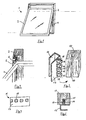
- Figure 1 shows a reversible window 1 comprising two main elements: a frame 2 and a sash 3.
- the frame 2 constitutes the outer part of the reversible window 1 and fits into an embrasure opening in a building.
- the sash 3 fits into the frame 2 and is provided with a sheet of glass.
- hinges 4 are provided at each side and configured such that the sash 3 can be tilted about a horizontal axis as shown in Figure 1 , then lowermost end of the sash 3 being shifted outwards, while the upper end remains in vertically displaceable engagement with the frame 2.
- the present invention lends itself for use in particular in connection with the displaceable engagement between the frame 2 and the sash 3, and all of the remaining configurative details of the frame 2, the sash 3 and the hinges 4 will not be subject to detailed discussion herein.
- the displaceable engagement between the frame 2 and the sash 3 comprises a U-shaped rail 5 mounted in the frame 2 and a slide element 6 being mounted turnably on the uppermost part of the sash 3.
- a rail 5 is mounted in both sides of the frame 2 and a slide element 6 is mounted in both sides of the sash 3.
- Figure 2 shows a simplified version of the reversible window 1 as it actually comprises more elements than the ones shown.
- the present invention relates to the rail 5 and in particular to its mounting in the frame 2. It is to be noted that the invention is not restricted to this specific use, as it lends itself for use just as readily in other contexts in which a rail is mounted in an element. Thus, in figures 3, 5 and 2 the frame 2 is therefore shown more schematically than in Figure 2 , and, moreover, it will be designated merely by the term "an element”.
- Figure 3 shows a U-shaped rail 15 and an element 12 in a first embodiment according to the invention immediately prior to the rail 15 being mounted in the element 12.
- the outside of the one leg in the U-shaped rail 15 constitutes an abutment face 17 that will, following mounting, adjoin the element 12.
- a plurality of engagement pins 18 are provided that have flange 19 that protrude latterally.
- the engagement pins 18 have a short expanse in the longitudinal direction of the rail 15 and are arranged at a relatively short mutual distance.
- the engagement pins 18 can advantageously have a square cross section and that the distance between the engagement pins 18 can be about two thirds of the expanse of the engagement pins 18 in the longitudinal direction of the rail 15. If thus the engagement pins 18 have a cross section of about 3 by 3 mm, the mutual distance between the engagement pins 18 is about 2 mm.
- the rail 15 can be moulded from plastics, metal or a composite material, since thereby the engagement pins 18 can be moulded in one operation simultaneously with the rail 15 as such.
- the rail 15, however, is extruded from eg aluminium as it is, as a starting point, configured with one continuous protrusion instead of the engagement pins 18.
- portions of the protrusion are removed at regular intervals, whereby a plurality of short engagement pins 18 are formed, as shown in Figure 3 .
- the element 12 is provided with a longitudinally extending groove 10 configured to receive the engagement pins 18 when the rail 15 is mounted on the element 2.
- the groove 10 has a width that corresponds essentially to the width of the engagement pins 18. However, preferably the width of the groove 10 is slightly smaller than the width of the engagement pins 18, whereby the engagement pins 18 are to be pressed into the groove 10 during mounting.
- the engagement pins 18 being provided with flange 19 that extend laterally and serve as barbs against the engagement pins 18 being unintentionally pulled out of the element 12 following mounting therein.
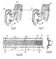
- the engagement pins 18 are twisted about their longitudinal axis. This will also appear from Figure 4 that shows the rail 15 shown in Figure 3 , seen in a direction towards the engagement pins 18.
- the twisting of the engagement pins 18 preferably takes place by application of a pressure in opposite directions on opposite sides of each engagement pin 18. It has been found that an angulation of the engagement pins 18 of about 22° provides good attachment force when the rail 15 is mounted in the groove 10 in the element 12.
- the first step in the preferred method is to apply an amount of glue 11 (see Figure 5 ) into the groove 10 of the element 12. Then the engagement pins 18 of the rail 15 are pressed into the groove 10, while the glue 11 distributes within the groove 10 underneath and between the protrusions 18.
- the groove 10 is preferably slightly narrower than the engagement pins 18, the outwardly protruding flange 19 of the engagement pins 18 will be pressed into the material of the element 12, which provides increased security against unintentional withdrawal of the engagement pin 18 from the element 12.
- the angle rotation of the engagement pins 18 prevents the rail 15 from being displaceable longitudinally of the groove 10 in the element 12.
- Figure 6 shows an alternative embodiment of a joint between an element and a rail according to the invention.
- a rail 25 is also provided with a plurality of engagement pins 28 that protrude from an abutment face 27 just like the rail 15 shown in figures 3-5 .
- the engagement pins 28 that are in turn provided with protruding flange 29, however, are arranged at a considerably larger mutual distance than the engagement pins 18 on the rail 15. This means that the distance is longer between the point loads on the side walls of the groove 10 in the element 12 when the rail 25 is mounted. The risk of the element 12 cracking when the rail 25 is mounted is thus smaller than when the rail 15 is mounted as shown in Figure 3 .
- the rail 25 is manufactured in the same manner as the rail 15, viz by initially extruding a slide rail with a continuous protrusion which is subsequently processed mechanically with removal of large portions of the protrusion until only a few separate engagement pins 28 remain which are spaced relatively far apart.
- the original continuous protrusion is preferably processed such that the engagement pins 28 are provided with flange 29 on all four sides as shown in Figure 6 .
- the first step in the preferred method is to apply an amount of glue into the groove 10 of the element 12. Then the engagement pins 28 of the rail 25 are pressed into the groove 10, while the glue 11 distributes within the groove 10 underneath and between the protrusions 28.
- the groove 10 is preferably slightly narrower than the engagement pins 28, the outwardly protruding flange 29 of the engagement pins 18 will be pressed into the material of the element 12, which provides increased security against unintentional withdrawal of the engagement pin 28 from the element 12.
- Those parts of the protruding flange 29 that are arranged on the sides of the engagement pins 28 that face towards each other will be surrounded by glue and therefore also contribute to securing the rail 25 against withdrawal.
- the rail 25 with engagement pins 28 as shown in Figure 6 can also be mounted on an element without a groove if the element is manufactured from a relatively soft material, such as fir, merely by the engagement pins 28 being pressed into the element.
- the engagement pins 28 are preferably configured to be comparatively thick, whereby there is only a small risk of them being deflected sideways if, for instance, they were to be pressed into a hard material in the element 22, such as a knot or the like.
- a row of bores 30 are preferably drilled as outlined by dotted lines, the distance between them corresponding, of course, to the mutual spacing between the engagement pins 28. If bores 30 are drilled an amount of glue is preferably applied in each bore before the rail 25 is mounted.
- the rail according to the invention can be moulded or manufactured by extrusion with subsequent processing of the engagement pins. It may be made of plastics, metal or a composite material; aluminium being, however, the preferred choice.
- Figures 8a and 8b illustrate how the rail 15 according to the first embodiment of the invention can be manufactured by extrusion and subsequent processing of the extruded profile.
- Figure 8a shows the extruded profile with different degrees of processing, section A showing the profile as it leaves the extruder, and Figure 8b showing a cross sectional view of the extruded profile along the section I-I shown in Figure 8a .
- the extruded profile comprises two laterally reversed U-shaped rails 15 that are joined at the tip of a protrusion 13 that points to the side.
- Section B of Figure 8a shows how a portion of the protrusion 13 has been removed, whereby engagement pins 18 are formed.
- this processing is made in a punching process, the extruded profile being conveyed into a punching tool that removes the desired portions of the protrusion 13.
- the engagement pins 18 having herein been angled.
- this angulation is performed in that a tool presses asymmetrically on opposed sides of each engagement pin 18, whereby it is turned as shown (see also Figure 4 ).
- the punching of portions of the protrusion 13 and the angulation of the engagement pins 18 preferably takes place in the same tool, a first part of the tool being configured to punch out parts of the protrusion 13, while another part is configured to press asymmetrically onto the engagement pins 18.
- the extruded profile is thus advanced through the tool.
- the two rails 15 are separated from each other.
- the element on which the rail is mounted may constitute a frame for a window as shown in figure 2 , but it is not limited thereto.
- the element can be manufactured from a suitable material, such as wood, plastics, polyurethane or a wooden composite material. The choice of material is of no consequence to the invention, but obviously the concrete configuration of the rail as well as the element must be adapted to the selected materials.
- the rail has a U-shaped profile.
- the invention is not limited to this configuration; a wide variety of embodiments of the rail being possible, depending on the intended use of the rail.
- the cross-sectional profile of the rail may thus have any desired shape, and likewise it may be curved in the longitudinal direction.
- the invention was described with reference to a reversible window, but the invention may just as well lend itself for use in many other contexts, in which a rail is to be mounted on an element in a concealed manner.
Landscapes
- Engineering & Computer Science (AREA)
- General Engineering & Computer Science (AREA)
- Mechanical Engineering (AREA)
- Support Devices For Sliding Doors (AREA)
- Machines For Laying And Maintaining Railways (AREA)
- Extrusion Of Metal (AREA)
- Mutual Connection Of Rods And Tubes (AREA)
Claims (14)
- Verbindung zwischen einem Element (2; 12) und einer länglichen Schiene (5; 15) mit einer an dem Element anliegenden Anlagefläche (17), wobei das Element (2; 12) mit einer sich in Längsrichtung erstreckenden Rille (10) versehen ist, und die Schiene (5; 15) mit einem sich von der Anlagefläche der Schiene erstreckenden Vorsprung versehen ist, wobei der Vorsprung relativ zu einer Längsrichtung der Schiene (5; 15) seitlich hervorsteht, sich in die in Längsrichtung sich erstreckende Rille (10) des Elements (2; 12) erstreckt und in eine Mehrheit von getrennten, in der Längsrichtung der Schiene voneinander beabstandeten Einraststiften (18) geteilt ist, dadurch gekennzeichnet, dass der Querschnitt der Einraststifte (18) relativ zur Längsrichtung der Schiene (15) abgewinkelt ist.
- Verbindung nach Anspruch 1, dadurch gekennzeichnet, dass der gegenseitige Abstand zwischen den Einraststiften (18) der gleichen Größenordnung ist wie die in der Längsrichtung der Schiene (15) bestehende Weite der Einraststifte.
- Verbindung nach Anspruch 1, dadurch gekennzeichnet, dass der gegenseitige Abstand zwischen den Einraststiften die in der Längsrichtung der Schiene bestehende Weite der Einraststifte wesentlich übersteigt.
- Verbindung nach einem der Ansprüche 1 bis 3, dadurch gekennzeichnet, dass zwischen den Einraststiften (8) und der Rille (10) ein Klebstoff (11) vorgesehen ist.
- Verbindung nach einem der Ansprüche 1 bis 4, dadurch gekennzeichnet, dass die Einraststifte (18) einen im Wesentlichen quadratischen Querschnitt aufweisen.
- Verbindung nach einem der Ansprüche 1 bis 5, dadurch gekennzeichnet, dass die Einraststifte (18) mit relativ zur Längsrichtung der Schiene (15) seitlich hervorstehenden Flanschen (19) versehen sind.
- Verbindung nach Anspruch 6, dadurch gekennzeichnet, dass die Einraststifte an den Seiten, die einander zugewandt sind, mit hervorstehenden Flanschen versehen sind.
- Verfahren zur Herstellung einer länglichen Schiene (5; 15) zur Befestigung an einem mit einer sich in Längsrichtung erstreckenden Rille (10) versehenen Element (2; 12), welches Verfahren den Schritt eines Strangpressens einer Schiene, welche einen seitlich hervorstehenden und sich relativ zu einer Längsrichtung der Schiene in Längsrichtung erstreckenden Vorsprung (13) aufweist, und den Schritt eines Entfernens von Abschnitten des Vorsprungs (13) umfasst, wodurch getrennte, in der Längsrichtung der Schiene (5; 15) gegenseitig voneinander beabstandete Einraststifte (18) gebildet werden, dadurch gekennzeichnet, dass die Einraststifte (18) durch einen an deren gegenüberliegenden Seiten beaufschlagten, asymmetrischen Druck relativ zur Längsrichtung der Schiene (15) abgewinkelt werden.
- Verfahren nach Anspruch 8, dadurch gekennzeichnet, dass so viel des Vorsprungs (13) entfernt wird, dass der gegenseitige Abstand zwischen den Einraststiften (18) der gleichen Größenordnung wird wie die in der Längsrichtung der Schiene (15) bestehende Weite der Einraststifte.
- Verfahren nach Anspruch 8, dadurch gekennzeichnet, dass so viel des Vorsprungs (13) entfernt wird, dass der gegenseitige Abstand zwischen den Einraststiften die in der Längsrichtung der Schiene bestehende Weite der Einraststifte wesentlich übersteigt.
- Verfahren nach den Ansprüchen 8 bis 10, dadurch gekennzeichnet, dass die Einraststifte (18) im Strangpressverfahren mit relativ zur Längsrichtung der Schiene (15) seitlich hervorstehenden Flanschen (19) versehen werden.
- Verfahren nach einem der Ansprüche 8 bis 11, dadurch gekennzeichnet, dass an den Seiten der Einraststifte, die einander zugewandt sind, bei dem Entfernen von Abschnitten des Vorsprungs (13) nach außen hervorstehende Flansche gebildet werden.
- Verfahren nach einem der Ansprüche 8 bis 12, dadurch gekennzeichnet, dass die stranggepresste Schiene (5; 15) mit dem kontinuierlichen, sich in Längsrichtung erstreckenden Vorsprung (13) einem Stanzwerkzeug zugeführt wird, welches durch Stanzen Abschnitte des Vorsprungs entfernt.
- Längliche Schiene (5; 15), welche eine Anlagefläche (17) zur Anlage an einem Element und einen relativ zu einer Längsrichtung der Schiene (5; 15) seitlich hervorstehenden Vorsprung aufweist, welcher Vorsprung in eine Mehrheit von getrennten, in der Längsrichtung der Schiene voneinander beabstandeten Einraststiften (18) geteilt ist, dadurch gekennzeichnet, dass der Querschnitt der Einraststifte (18) relativ zur Längsrichtung der Schiene (15) abgewinkelt ist.
Applications Claiming Priority (2)
| Application Number | Priority Date | Filing Date | Title |
|---|---|---|---|
| DKPA200300974 | 2003-06-27 | ||
| PCT/DK2004/000443 WO2005001297A1 (en) | 2003-06-27 | 2004-06-23 | A joint between an element and a rail, and a method of manufacturing a rail for such joint |
Publications (2)
| Publication Number | Publication Date |
|---|---|
| EP1639263A1 EP1639263A1 (de) | 2006-03-29 |
| EP1639263B1 true EP1639263B1 (de) | 2011-08-17 |
Family
ID=33547543
Family Applications (1)
| Application Number | Title | Priority Date | Filing Date |
|---|---|---|---|
| EP04738940A Expired - Lifetime EP1639263B1 (de) | 2003-06-27 | 2004-06-23 | Eine verbindung zwischen einem element und einer schiene und ein verfahren zur herstellung einer schiene für solch eine verbindung und schiene |
Country Status (4)
| Country | Link |
|---|---|
| EP (1) | EP1639263B1 (de) |
| AT (1) | ATE520885T1 (de) |
| DK (1) | DK1639263T3 (de) |
| WO (1) | WO2005001297A1 (de) |
Family Cites Families (5)
| Publication number | Priority date | Publication date | Assignee | Title |
|---|---|---|---|---|
| US246949A (en) | 1881-09-13 | gkuneberg | ||
| CA1012731A (en) | 1974-08-30 | 1977-06-28 | Beaconfield Consulting Services Limited | Attaching means for members at an angle to one another |
| US4199910A (en) * | 1978-08-23 | 1980-04-29 | Priore Alfred J | T-shaped edge finishing strips and their production |
| US4971849A (en) * | 1989-08-14 | 1990-11-20 | Extrusions Division | Readily bendable extruded elastomeric trim strip |
| DE9115404U1 (de) * | 1991-12-12 | 1992-02-06 | REHAU AG + Co, 8673 Rehau | Abdeckprofil für Plattenkanten |
-
2004
- 2004-06-23 DK DK04738940.8T patent/DK1639263T3/da active
- 2004-06-23 WO PCT/DK2004/000443 patent/WO2005001297A1/en not_active Ceased
- 2004-06-23 EP EP04738940A patent/EP1639263B1/de not_active Expired - Lifetime
- 2004-06-23 AT AT04738940T patent/ATE520885T1/de not_active IP Right Cessation
Also Published As
| Publication number | Publication date |
|---|---|
| WO2005001297A1 (en) | 2005-01-06 |
| EP1639263A1 (de) | 2006-03-29 |
| DK1639263T3 (da) | 2011-11-14 |
| ATE520885T1 (de) | 2011-09-15 |
Similar Documents
| Publication | Publication Date | Title |
|---|---|---|
| US5845439A (en) | Adjustable door and frame assembly | |
| US11268294B2 (en) | Snap fit posts for fence panels balustrades and the like | |
| DE20321760U1 (de) | Tür mit Isolierverglasung und damit ausgestattetes Haushaltsgerät | |
| EP2136025B2 (de) | Tor | |
| EP3379016A1 (de) | Schiebeelement mit dichtungsvorrichtung und dichtungselement | |
| EP1285143A1 (de) | Profilleiste für den übergang zwischen bauteil und gebäudefläche | |
| EP2206871A1 (de) | Profilsystem für eine Schiebetür | |
| DE102005057134A1 (de) | Kältegerät mit Dekorrahmen | |
| EP1405979B1 (de) | Verbindungsvorrichtung, Abdeckvorrichtung und Trennelement | |
| EP1020579B1 (de) | Fassade oder Lichtdach mit einer Dichtung | |
| DE29916942U1 (de) | Verbundfenster | |
| US20060248820A1 (en) | Integrally extruded glazing member for a sash assembly | |
| EP2010031B1 (de) | Tür für ein kältegerät | |
| EP1680563B1 (de) | Anordnung zur Verbindung von Bodenbelägen | |
| EP1639263B1 (de) | Eine verbindung zwischen einem element und einer schiene und ein verfahren zur herstellung einer schiene für solch eine verbindung und schiene | |
| DE102005056439B4 (de) | Profilleiste zur Verwendung im Innenausbau sowie Bausatz einschließlich einer solchen Profilleiste | |
| EP1746240A1 (de) | Dichtungseinrichtung für den unteren Rand einer Tür | |
| EP1497520B1 (de) | Sektionaltor | |
| EP1361329B1 (de) | Türschwellenanordnung | |
| EP2171175B1 (de) | Putzanschlussleiste für die laibung von fenstern und türen | |
| EP3414416B1 (de) | Verglasungsprofile mit nahtlosem aussehen und verfahren zur verwendung | |
| DE4039386C2 (de) | Elastisches Strangdichtungsprofil zum Abdichten von Verglasungen in Flügeln von Holzfenstern oder Holztüren | |
| DE20200035U1 (de) | Vorrichtung zum Abdichten der Schließfuge der Scheibe einer Glastür o.dgl. | |
| EP1683940A2 (de) | Fenster oder Tür mit eingeklebter Verglasung | |
| DE4010081A1 (de) | Fenster, tuer o. dgl. fuer gebaeude mit einer verglasung |
Legal Events
| Date | Code | Title | Description |
|---|---|---|---|
| PUAI | Public reference made under article 153(3) epc to a published international application that has entered the european phase |
Free format text: ORIGINAL CODE: 0009012 |
|
| 17P | Request for examination filed |
Effective date: 20051215 |
|
| AK | Designated contracting states |
Kind code of ref document: A1 Designated state(s): AT BE BG CH CY CZ DE DK EE ES FI FR GB GR HU IE IT LI LU MC NL PL PT RO SE SI SK TR |
|
| DAX | Request for extension of the european patent (deleted) | ||
| RAP1 | Party data changed (applicant data changed or rights of an application transferred) |
Owner name: VKR HOLDING A/S |
|
| RTI1 | Title (correction) |
Free format text: A JOINT BETWEEN AN ELEMENT AND A RAIL, AND A METHOD OF MANUFACTURING A RAIL FOR SUCH JOINT AND A RAIL& XA; |
|
| GRAP | Despatch of communication of intention to grant a patent |
Free format text: ORIGINAL CODE: EPIDOSNIGR1 |
|
| GRAS | Grant fee paid |
Free format text: ORIGINAL CODE: EPIDOSNIGR3 |
|
| GRAA | (expected) grant |
Free format text: ORIGINAL CODE: 0009210 |
|
| AK | Designated contracting states |
Kind code of ref document: B1 Designated state(s): AT BE BG CH CY CZ DE DK EE ES FI FR GB GR HU IE IT LI LU MC NL PL PT RO SE SI SK TR |
|
| REG | Reference to a national code |
Ref country code: GB Ref legal event code: FG4D |
|
| REG | Reference to a national code |
Ref country code: CH Ref legal event code: EP |
|
| REG | Reference to a national code |
Ref country code: IE Ref legal event code: FG4D |
|
| REG | Reference to a national code |
Ref country code: DE Ref legal event code: R096 Ref document number: 602004033993 Country of ref document: DE Effective date: 20111013 |
|
| REG | Reference to a national code |
Ref country code: DK Ref legal event code: T3 |
|
| REG | Reference to a national code |
Ref country code: NL Ref legal event code: VDEP Effective date: 20110817 |
|
| PG25 | Lapsed in a contracting state [announced via postgrant information from national office to epo] |
Ref country code: SE Free format text: LAPSE BECAUSE OF FAILURE TO SUBMIT A TRANSLATION OF THE DESCRIPTION OR TO PAY THE FEE WITHIN THE PRESCRIBED TIME-LIMIT Effective date: 20110817 Ref country code: PT Free format text: LAPSE BECAUSE OF FAILURE TO SUBMIT A TRANSLATION OF THE DESCRIPTION OR TO PAY THE FEE WITHIN THE PRESCRIBED TIME-LIMIT Effective date: 20111219 Ref country code: FI Free format text: LAPSE BECAUSE OF FAILURE TO SUBMIT A TRANSLATION OF THE DESCRIPTION OR TO PAY THE FEE WITHIN THE PRESCRIBED TIME-LIMIT Effective date: 20110817 Ref country code: NL Free format text: LAPSE BECAUSE OF FAILURE TO SUBMIT A TRANSLATION OF THE DESCRIPTION OR TO PAY THE FEE WITHIN THE PRESCRIBED TIME-LIMIT Effective date: 20110817 |
|
| REG | Reference to a national code |
Ref country code: AT Ref legal event code: MK05 Ref document number: 520885 Country of ref document: AT Kind code of ref document: T Effective date: 20110817 |
|
| PG25 | Lapsed in a contracting state [announced via postgrant information from national office to epo] |
Ref country code: PL Free format text: LAPSE BECAUSE OF FAILURE TO SUBMIT A TRANSLATION OF THE DESCRIPTION OR TO PAY THE FEE WITHIN THE PRESCRIBED TIME-LIMIT Effective date: 20110817 Ref country code: SI Free format text: LAPSE BECAUSE OF FAILURE TO SUBMIT A TRANSLATION OF THE DESCRIPTION OR TO PAY THE FEE WITHIN THE PRESCRIBED TIME-LIMIT Effective date: 20110817 Ref country code: CY Free format text: LAPSE BECAUSE OF FAILURE TO SUBMIT A TRANSLATION OF THE DESCRIPTION OR TO PAY THE FEE WITHIN THE PRESCRIBED TIME-LIMIT Effective date: 20110817 Ref country code: AT Free format text: LAPSE BECAUSE OF FAILURE TO SUBMIT A TRANSLATION OF THE DESCRIPTION OR TO PAY THE FEE WITHIN THE PRESCRIBED TIME-LIMIT Effective date: 20110817 Ref country code: GR Free format text: LAPSE BECAUSE OF FAILURE TO SUBMIT A TRANSLATION OF THE DESCRIPTION OR TO PAY THE FEE WITHIN THE PRESCRIBED TIME-LIMIT Effective date: 20111118 |
|
| PG25 | Lapsed in a contracting state [announced via postgrant information from national office to epo] |
Ref country code: BE Free format text: LAPSE BECAUSE OF FAILURE TO SUBMIT A TRANSLATION OF THE DESCRIPTION OR TO PAY THE FEE WITHIN THE PRESCRIBED TIME-LIMIT Effective date: 20110817 |
|
| PG25 | Lapsed in a contracting state [announced via postgrant information from national office to epo] |
Ref country code: SK Free format text: LAPSE BECAUSE OF FAILURE TO SUBMIT A TRANSLATION OF THE DESCRIPTION OR TO PAY THE FEE WITHIN THE PRESCRIBED TIME-LIMIT Effective date: 20110817 Ref country code: CZ Free format text: LAPSE BECAUSE OF FAILURE TO SUBMIT A TRANSLATION OF THE DESCRIPTION OR TO PAY THE FEE WITHIN THE PRESCRIBED TIME-LIMIT Effective date: 20110817 |
|
| PG25 | Lapsed in a contracting state [announced via postgrant information from national office to epo] |
Ref country code: RO Free format text: LAPSE BECAUSE OF FAILURE TO SUBMIT A TRANSLATION OF THE DESCRIPTION OR TO PAY THE FEE WITHIN THE PRESCRIBED TIME-LIMIT Effective date: 20110817 Ref country code: IT Free format text: LAPSE BECAUSE OF FAILURE TO SUBMIT A TRANSLATION OF THE DESCRIPTION OR TO PAY THE FEE WITHIN THE PRESCRIBED TIME-LIMIT Effective date: 20110817 Ref country code: EE Free format text: LAPSE BECAUSE OF FAILURE TO SUBMIT A TRANSLATION OF THE DESCRIPTION OR TO PAY THE FEE WITHIN THE PRESCRIBED TIME-LIMIT Effective date: 20110817 |
|
| PLBE | No opposition filed within time limit |
Free format text: ORIGINAL CODE: 0009261 |
|
| STAA | Information on the status of an ep patent application or granted ep patent |
Free format text: STATUS: NO OPPOSITION FILED WITHIN TIME LIMIT |
|
| 26N | No opposition filed |
Effective date: 20120521 |
|
| REG | Reference to a national code |
Ref country code: DE Ref legal event code: R097 Ref document number: 602004033993 Country of ref document: DE Effective date: 20120521 |
|
| PG25 | Lapsed in a contracting state [announced via postgrant information from national office to epo] |
Ref country code: MC Free format text: LAPSE BECAUSE OF NON-PAYMENT OF DUE FEES Effective date: 20120630 |
|
| REG | Reference to a national code |
Ref country code: CH Ref legal event code: PL |
|
| REG | Reference to a national code |
Ref country code: CH Ref legal event code: PL |
|
| REG | Reference to a national code |
Ref country code: IE Ref legal event code: MM4A |
|
| REG | Reference to a national code |
Ref country code: FR Ref legal event code: ST Effective date: 20130228 |
|
| REG | Reference to a national code |
Ref country code: DE Ref legal event code: R119 Ref document number: 602004033993 Country of ref document: DE Effective date: 20130101 |
|
| PG25 | Lapsed in a contracting state [announced via postgrant information from national office to epo] |
Ref country code: CH Free format text: LAPSE BECAUSE OF NON-PAYMENT OF DUE FEES Effective date: 20120630 Ref country code: DE Free format text: LAPSE BECAUSE OF NON-PAYMENT OF DUE FEES Effective date: 20130101 Ref country code: LI Free format text: LAPSE BECAUSE OF NON-PAYMENT OF DUE FEES Effective date: 20120630 Ref country code: ES Free format text: LAPSE BECAUSE OF FAILURE TO SUBMIT A TRANSLATION OF THE DESCRIPTION OR TO PAY THE FEE WITHIN THE PRESCRIBED TIME-LIMIT Effective date: 20111128 Ref country code: IE Free format text: LAPSE BECAUSE OF NON-PAYMENT OF DUE FEES Effective date: 20120623 Ref country code: FR Free format text: LAPSE BECAUSE OF NON-PAYMENT OF DUE FEES Effective date: 20120702 |
|
| PG25 | Lapsed in a contracting state [announced via postgrant information from national office to epo] |
Ref country code: BG Free format text: LAPSE BECAUSE OF FAILURE TO SUBMIT A TRANSLATION OF THE DESCRIPTION OR TO PAY THE FEE WITHIN THE PRESCRIBED TIME-LIMIT Effective date: 20111117 |
|
| PGFP | Annual fee paid to national office [announced via postgrant information from national office to epo] |
Ref country code: GB Payment date: 20130619 Year of fee payment: 10 Ref country code: DK Payment date: 20130611 Year of fee payment: 10 |
|
| PG25 | Lapsed in a contracting state [announced via postgrant information from national office to epo] |
Ref country code: TR Free format text: LAPSE BECAUSE OF FAILURE TO SUBMIT A TRANSLATION OF THE DESCRIPTION OR TO PAY THE FEE WITHIN THE PRESCRIBED TIME-LIMIT Effective date: 20110817 |
|
| PG25 | Lapsed in a contracting state [announced via postgrant information from national office to epo] |
Ref country code: LU Free format text: LAPSE BECAUSE OF NON-PAYMENT OF DUE FEES Effective date: 20120623 |
|
| PG25 | Lapsed in a contracting state [announced via postgrant information from national office to epo] |
Ref country code: HU Free format text: LAPSE BECAUSE OF FAILURE TO SUBMIT A TRANSLATION OF THE DESCRIPTION OR TO PAY THE FEE WITHIN THE PRESCRIBED TIME-LIMIT Effective date: 20040623 |
|
| REG | Reference to a national code |
Ref country code: DK Ref legal event code: EBP Effective date: 20140630 |
|
| GBPC | Gb: european patent ceased through non-payment of renewal fee |
Effective date: 20140623 |
|
| PG25 | Lapsed in a contracting state [announced via postgrant information from national office to epo] |
Ref country code: GB Free format text: LAPSE BECAUSE OF NON-PAYMENT OF DUE FEES Effective date: 20140623 |
|
| PG25 | Lapsed in a contracting state [announced via postgrant information from national office to epo] |
Ref country code: DK Free format text: LAPSE BECAUSE OF NON-PAYMENT OF DUE FEES Effective date: 20140630 |