EP1637950A1 - Device for dividing and feeding gas flow from flow rate- regulating device-equipped gas-feeding equipment to chamber - Google Patents
Device for dividing and feeding gas flow from flow rate- regulating device-equipped gas-feeding equipment to chamber Download PDFInfo
- Publication number
- EP1637950A1 EP1637950A1 EP20040745747 EP04745747A EP1637950A1 EP 1637950 A1 EP1637950 A1 EP 1637950A1 EP 20040745747 EP20040745747 EP 20040745747 EP 04745747 A EP04745747 A EP 04745747A EP 1637950 A1 EP1637950 A1 EP 1637950A1
- Authority
- EP
- European Patent Office
- Prior art keywords
- pressure
- gas
- open
- branch supply
- flow rate
- Prior art date
- Legal status (The legal status is an assumption and is not a legal conclusion. Google has not performed a legal analysis and makes no representation as to the accuracy of the status listed.)
- Withdrawn
Links
- 230000001105 regulatory effect Effects 0.000 title claims description 15
- 238000000034 method Methods 0.000 claims description 22
- 238000012545 processing Methods 0.000 abstract description 20
- 238000004891 communication Methods 0.000 description 23
- 238000011144 upstream manufacturing Methods 0.000 description 12
- 238000004519 manufacturing process Methods 0.000 description 6
- 239000004065 semiconductor Substances 0.000 description 5
- 230000000694 effects Effects 0.000 description 4
- 238000010586 diagram Methods 0.000 description 3
- 230000001419 dependent effect Effects 0.000 description 2
- VYPSYNLAJGMNEJ-UHFFFAOYSA-N Silicium dioxide Chemical compound O=[Si]=O VYPSYNLAJGMNEJ-UHFFFAOYSA-N 0.000 description 1
- XUIMIQQOPSSXEZ-UHFFFAOYSA-N Silicon Chemical compound [Si] XUIMIQQOPSSXEZ-UHFFFAOYSA-N 0.000 description 1
- 230000005856 abnormality Effects 0.000 description 1
- 230000003321 amplification Effects 0.000 description 1
- 238000007796 conventional method Methods 0.000 description 1
- 239000013256 coordination polymer Substances 0.000 description 1
- 239000012530 fluid Substances 0.000 description 1
- 238000009434 installation Methods 0.000 description 1
- 238000012423 maintenance Methods 0.000 description 1
- 239000002184 metal Substances 0.000 description 1
- 238000003199 nucleic acid amplification method Methods 0.000 description 1
- 230000002093 peripheral effect Effects 0.000 description 1
- 239000000825 pharmaceutical preparation Substances 0.000 description 1
- 229940127557 pharmaceutical product Drugs 0.000 description 1
- 230000009467 reduction Effects 0.000 description 1
- 229910052710 silicon Inorganic materials 0.000 description 1
- 239000010703 silicon Substances 0.000 description 1
- 229910052814 silicon oxide Inorganic materials 0.000 description 1
- 239000000126 substance Substances 0.000 description 1
Images



Classifications
-
- G—PHYSICS
- G05—CONTROLLING; REGULATING
- G05D—SYSTEMS FOR CONTROLLING OR REGULATING NON-ELECTRIC VARIABLES
- G05D7/00—Control of flow
-
- G—PHYSICS
- G05—CONTROLLING; REGULATING
- G05D—SYSTEMS FOR CONTROLLING OR REGULATING NON-ELECTRIC VARIABLES
- G05D7/00—Control of flow
- G05D7/06—Control of flow characterised by the use of electric means
-
- G—PHYSICS
- G05—CONTROLLING; REGULATING
- G05D—SYSTEMS FOR CONTROLLING OR REGULATING NON-ELECTRIC VARIABLES
- G05D11/00—Control of flow ratio
- G05D11/02—Controlling ratio of two or more flows of fluid or fluent material
- G05D11/13—Controlling ratio of two or more flows of fluid or fluent material characterised by the use of electric means
- G05D11/131—Controlling ratio of two or more flows of fluid or fluent material characterised by the use of electric means by measuring the values related to the quantity of the individual components
- G05D11/132—Controlling ratio of two or more flows of fluid or fluent material characterised by the use of electric means by measuring the values related to the quantity of the individual components by controlling the flow of the individual components
-
- G—PHYSICS
- G05—CONTROLLING; REGULATING
- G05D—SYSTEMS FOR CONTROLLING OR REGULATING NON-ELECTRIC VARIABLES
- G05D7/00—Control of flow
- G05D7/06—Control of flow characterised by the use of electric means
- G05D7/0617—Control of flow characterised by the use of electric means specially adapted for fluid materials
- G05D7/0623—Control of flow characterised by the use of electric means specially adapted for fluid materials characterised by the set value given to the control element
-
- G—PHYSICS
- G05—CONTROLLING; REGULATING
- G05D—SYSTEMS FOR CONTROLLING OR REGULATING NON-ELECTRIC VARIABLES
- G05D7/00—Control of flow
- G05D7/06—Control of flow characterised by the use of electric means
- G05D7/0617—Control of flow characterised by the use of electric means specially adapted for fluid materials
- G05D7/0629—Control of flow characterised by the use of electric means specially adapted for fluid materials characterised by the type of regulator means
- G05D7/0635—Control of flow characterised by the use of electric means specially adapted for fluid materials characterised by the type of regulator means by action on throttling means
- G05D7/0641—Control of flow characterised by the use of electric means specially adapted for fluid materials characterised by the type of regulator means by action on throttling means using a plurality of throttling means
- G05D7/0652—Control of flow characterised by the use of electric means specially adapted for fluid materials characterised by the type of regulator means by action on throttling means using a plurality of throttling means the plurality of throttling means being arranged in parallel
-
- G—PHYSICS
- G05—CONTROLLING; REGULATING
- G05D—SYSTEMS FOR CONTROLLING OR REGULATING NON-ELECTRIC VARIABLES
- G05D7/00—Control of flow
- G05D7/06—Control of flow characterised by the use of electric means
- G05D7/0617—Control of flow characterised by the use of electric means specially adapted for fluid materials
- G05D7/0629—Control of flow characterised by the use of electric means specially adapted for fluid materials characterised by the type of regulator means
- G05D7/0635—Control of flow characterised by the use of electric means specially adapted for fluid materials characterised by the type of regulator means by action on throttling means
- G05D7/0641—Control of flow characterised by the use of electric means specially adapted for fluid materials characterised by the type of regulator means by action on throttling means using a plurality of throttling means
- G05D7/0658—Control of flow characterised by the use of electric means specially adapted for fluid materials characterised by the type of regulator means by action on throttling means using a plurality of throttling means the plurality of throttling means being arranged for the control of a single flow from a plurality of converging flows
-
- G—PHYSICS
- G05—CONTROLLING; REGULATING
- G05D—SYSTEMS FOR CONTROLLING OR REGULATING NON-ELECTRIC VARIABLES
- G05D7/00—Control of flow
- G05D7/06—Control of flow characterised by the use of electric means
- G05D7/0617—Control of flow characterised by the use of electric means specially adapted for fluid materials
- G05D7/0629—Control of flow characterised by the use of electric means specially adapted for fluid materials characterised by the type of regulator means
- G05D7/0635—Control of flow characterised by the use of electric means specially adapted for fluid materials characterised by the type of regulator means by action on throttling means
- G05D7/0641—Control of flow characterised by the use of electric means specially adapted for fluid materials characterised by the type of regulator means by action on throttling means using a plurality of throttling means
- G05D7/0664—Control of flow characterised by the use of electric means specially adapted for fluid materials characterised by the type of regulator means by action on throttling means using a plurality of throttling means the plurality of throttling means being arranged for the control of a plurality of diverging flows from a single flow
-
- Y—GENERAL TAGGING OF NEW TECHNOLOGICAL DEVELOPMENTS; GENERAL TAGGING OF CROSS-SECTIONAL TECHNOLOGIES SPANNING OVER SEVERAL SECTIONS OF THE IPC; TECHNICAL SUBJECTS COVERED BY FORMER USPC CROSS-REFERENCE ART COLLECTIONS [XRACs] AND DIGESTS
- Y10—TECHNICAL SUBJECTS COVERED BY FORMER USPC
- Y10T—TECHNICAL SUBJECTS COVERED BY FORMER US CLASSIFICATION
- Y10T137/00—Fluid handling
- Y10T137/0318—Processes
- Y10T137/0324—With control of flow by a condition or characteristic of a fluid
- Y10T137/0379—By fluid pressure
-
- Y—GENERAL TAGGING OF NEW TECHNOLOGICAL DEVELOPMENTS; GENERAL TAGGING OF CROSS-SECTIONAL TECHNOLOGIES SPANNING OVER SEVERAL SECTIONS OF THE IPC; TECHNICAL SUBJECTS COVERED BY FORMER USPC CROSS-REFERENCE ART COLLECTIONS [XRACs] AND DIGESTS
- Y10—TECHNICAL SUBJECTS COVERED BY FORMER USPC
- Y10T—TECHNICAL SUBJECTS COVERED BY FORMER US CLASSIFICATION
- Y10T137/00—Fluid handling
- Y10T137/0318—Processes
- Y10T137/0396—Involving pressure control
-
- Y—GENERAL TAGGING OF NEW TECHNOLOGICAL DEVELOPMENTS; GENERAL TAGGING OF CROSS-SECTIONAL TECHNOLOGIES SPANNING OVER SEVERAL SECTIONS OF THE IPC; TECHNICAL SUBJECTS COVERED BY FORMER USPC CROSS-REFERENCE ART COLLECTIONS [XRACs] AND DIGESTS
- Y10—TECHNICAL SUBJECTS COVERED BY FORMER USPC
- Y10T—TECHNICAL SUBJECTS COVERED BY FORMER US CLASSIFICATION
- Y10T137/00—Fluid handling
- Y10T137/2496—Self-proportioning or correlating systems
- Y10T137/2514—Self-proportioning flow systems
- Y10T137/2521—Flow comparison or differential response
-
- Y—GENERAL TAGGING OF NEW TECHNOLOGICAL DEVELOPMENTS; GENERAL TAGGING OF CROSS-SECTIONAL TECHNOLOGIES SPANNING OVER SEVERAL SECTIONS OF THE IPC; TECHNICAL SUBJECTS COVERED BY FORMER USPC CROSS-REFERENCE ART COLLECTIONS [XRACs] AND DIGESTS
- Y10—TECHNICAL SUBJECTS COVERED BY FORMER USPC
- Y10T—TECHNICAL SUBJECTS COVERED BY FORMER US CLASSIFICATION
- Y10T137/00—Fluid handling
- Y10T137/2496—Self-proportioning or correlating systems
- Y10T137/2514—Self-proportioning flow systems
- Y10T137/2521—Flow comparison or differential response
- Y10T137/2529—With electrical controller
-
- Y—GENERAL TAGGING OF NEW TECHNOLOGICAL DEVELOPMENTS; GENERAL TAGGING OF CROSS-SECTIONAL TECHNOLOGIES SPANNING OVER SEVERAL SECTIONS OF THE IPC; TECHNICAL SUBJECTS COVERED BY FORMER USPC CROSS-REFERENCE ART COLLECTIONS [XRACs] AND DIGESTS
- Y10—TECHNICAL SUBJECTS COVERED BY FORMER USPC
- Y10T—TECHNICAL SUBJECTS COVERED BY FORMER US CLASSIFICATION
- Y10T137/00—Fluid handling
- Y10T137/2496—Self-proportioning or correlating systems
- Y10T137/2559—Self-controlled branched flow systems
- Y10T137/2562—Dividing and recombining
-
- Y—GENERAL TAGGING OF NEW TECHNOLOGICAL DEVELOPMENTS; GENERAL TAGGING OF CROSS-SECTIONAL TECHNOLOGIES SPANNING OVER SEVERAL SECTIONS OF THE IPC; TECHNICAL SUBJECTS COVERED BY FORMER USPC CROSS-REFERENCE ART COLLECTIONS [XRACs] AND DIGESTS
- Y10—TECHNICAL SUBJECTS COVERED BY FORMER USPC
- Y10T—TECHNICAL SUBJECTS COVERED BY FORMER US CLASSIFICATION
- Y10T137/00—Fluid handling
- Y10T137/2496—Self-proportioning or correlating systems
- Y10T137/2559—Self-controlled branched flow systems
- Y10T137/2574—Bypass or relief controlled by main line fluid condition
- Y10T137/2605—Pressure responsive
- Y10T137/263—Plural sensors for single bypass or relief valve
-
- Y—GENERAL TAGGING OF NEW TECHNOLOGICAL DEVELOPMENTS; GENERAL TAGGING OF CROSS-SECTIONAL TECHNOLOGIES SPANNING OVER SEVERAL SECTIONS OF THE IPC; TECHNICAL SUBJECTS COVERED BY FORMER USPC CROSS-REFERENCE ART COLLECTIONS [XRACs] AND DIGESTS
- Y10—TECHNICAL SUBJECTS COVERED BY FORMER USPC
- Y10T—TECHNICAL SUBJECTS COVERED BY FORMER US CLASSIFICATION
- Y10T137/00—Fluid handling
- Y10T137/2496—Self-proportioning or correlating systems
- Y10T137/2559—Self-controlled branched flow systems
- Y10T137/265—Plural outflows
- Y10T137/2663—Pressure responsive
-
- Y—GENERAL TAGGING OF NEW TECHNOLOGICAL DEVELOPMENTS; GENERAL TAGGING OF CROSS-SECTIONAL TECHNOLOGIES SPANNING OVER SEVERAL SECTIONS OF THE IPC; TECHNICAL SUBJECTS COVERED BY FORMER USPC CROSS-REFERENCE ART COLLECTIONS [XRACs] AND DIGESTS
- Y10—TECHNICAL SUBJECTS COVERED BY FORMER USPC
- Y10T—TECHNICAL SUBJECTS COVERED BY FORMER US CLASSIFICATION
- Y10T137/00—Fluid handling
- Y10T137/7722—Line condition change responsive valves
- Y10T137/7758—Pilot or servo controlled
- Y10T137/7761—Electrically actuated valve
-
- Y—GENERAL TAGGING OF NEW TECHNOLOGICAL DEVELOPMENTS; GENERAL TAGGING OF CROSS-SECTIONAL TECHNOLOGIES SPANNING OVER SEVERAL SECTIONS OF THE IPC; TECHNICAL SUBJECTS COVERED BY FORMER USPC CROSS-REFERENCE ART COLLECTIONS [XRACs] AND DIGESTS
- Y10—TECHNICAL SUBJECTS COVERED BY FORMER USPC
- Y10T—TECHNICAL SUBJECTS COVERED BY FORMER US CLASSIFICATION
- Y10T137/00—Fluid handling
- Y10T137/8158—With indicator, register, recorder, alarm or inspection means
- Y10T137/8175—Plural
Definitions
- the present invention is to be used for semiconductor manufacturing facilities, and is concerned with improvements in supplying gas while automatically dividing to a chamber from a gas supplying facility equipped with a flow controller.
- FIG. 5 illustrates an example in the event that processing gas G is supplied into a chamber to form a silicon oxide film using a pressure type flow controller FCS.
- a specified quantity Q of processing gas G is supplied to a pressure-reduced chamber C by using a vacuum pump Vp, and a quantity Q of processing gas G is discharged to a wafer H on the supporting device I through a gas discharger D.
- P 0 designates supply pressure of processing gas G, Pm a manometer, F a filter, CPU a central processing unit, Qs an input signal for a flow rate setting, and Qe an output signal for control of the flow rate.
- a pressure type flow controller itself has been publicly disclosed with the TOKU-KAI-HEI No.8-338546, the TOKU-KAI-HEI No.11-63265 and others. Therefore, detailed explanations are omitted herewith.
- processing gas can be supplied to the afore-mentioned center part and edge part respectively by providing separate branch supply lines GL 1 and GL 2 as shown in Figure 6, thus being able to supply processing gas G without any difficulties from a gas supply source S with specified quantities Q1 and Q 2 even with gas supply lines GL 1 and GL 2 wherewith a pressure type flow controller FCS.
- FCS pressure type flow controller
- both control valves V 1 and V 2 are first placed in a state of being fully closed, and a flow rate Q (300SCCM) of the pressure type flow controller FCS is set. Then, the degree of opening of both control valves V 1 and V 2 are adjusted to the flow rate Q 1 (130SCCM) and Q 2 (170 SCCM) for branch supply lines GL1 and GL 2 . This, however, finds it difficult to control the flow rates accurately and quickly.
- the method employed in the TOKU-GAN-HEI No.2002-161086 made it possible that flow rates Q 1 and Q 2 of branch supply lines GL 1 and GL 2 are regulated at a desired flow rate ratio Q 1 /Q 2 accurately and quickly.
- the method made the control complicated because it employed two pressure type division quantity controllers FV 1 and FV 2 beside a pressure type flow controller FCS for regulating pressure on both sides, thus inviting another problem of facility costs becoming higher.
- inventors of the present invention have developed a device and a method, simply structured and manufactured at low costs, for supplying gas while dividing to a chamber from a gas supply facility accurately and quickly.
- the present invention as claimed in Claim 1 is fundamentally so constituted that, with a device for supplying a specified quantity Q of gas G while dividing at a specified flow rate ratio Q 1 /Q 2 from a gas supply facility 1 provided with a flow controller QCS into a chamber C through a plurality of branch supply lines GL 1 and GL 2 and shower plates 3 and 4 fixed to the ends thereof, open/close valves OV 1 and OV 2 are provided with an afore-mentioned plurality of branch supply lines GL 1 and GL 2 respectively, and also a bypass line BL 1 on the downstream side of an open/close valve OV 1 and branched from the branch supply line GL 1 , a bypass line BL 2 on the downstream side of an open/close valve OV 2 and branched from the branch supply line GL 2 , a pressure type division quantity controller FV connected to the afore-mentioned bypass lines BL 1 and BL 2 , a pressure sensor PS 1 to measure pressure inside the branch supply line GL
- the present invention as claimed in Claim 2 according to Claim 1 is fundamentally so constituted that a control device CT to regulate the degree of opening of a pressure type division quantity controller FV is provided to reduce the difference between actual pressure of the branch supply line and set pressure to reach the specified flow rate ratio Q 1 /Q 2 by comparing either one of set pressure Pl1 or Pl2 of the branch supply lines GL 1 and GL 2 to reach the specified flow rate ratio Q 1 /Q 2 with corresponding actual pressure PT 1 or PT 2 of the branch supply lines GL 1 or GL 2 measured by the pressure sensor PS 1 or the pressure sensor PS 2 .
- the present invention as claimed in Claim 3 according to Claim 1 or Claim 2 is fundamentally so constituted that an open/close valve OV 1 and an open/close valve OV 2 are pneumatically operated, and a switch valve SV is provided for supplying actuating air to the open/close valve OV 1 and the open/close valve OV 2 .
- Claim 4 As claimed in Claim 4 according to Claim 1, Claim 2 or Claim 3 is fundamentally so constituted that an open/close valve OV 1 and an open/close valve OV 2 are made to be integrated.
- Claim 5 The present invention as claimed in Claim 5 according to Claim 1, Claim 2, Claim 3 or Claim 4 is fundamentally so constituted that a pressure type flow controller FCS is used for a flow controller QCS.
- the present invention as claimed in Claim 6 is fundamentally so constituted that, with a method for supplying a specified quantity Q of gas G while dividing at a specified flow rate ratio Q 1 /Q 2 from a gas supply facility 1 provided with a flow controller QCS into a chamber C through a plurality of branch supply lines GL 1 and GL 2 and shower plates 3 and 4 fixed to the ends thereof, open/close valves OV 1 and OV 2 are installed on an afore-mentioned plurality of branch supply lines GL 1 and GL 2 respectively, and also a bypass line BL1 on the downstream side of an open/close valve OV 1 and branched from the branch supply line GL 1 , a bypass line BL2 on the downstream side of an open/close valve OV 2 and branched from the branch supply line GL 2 , a pressure type division quantity controller FV connected to the afore-mentioned bypass lines BL1 and BL2, and further a pressure sensor PS 1 to measure pressure inside the branch supply line GL
- the present invention as claimed in Claim 7 according to Claim 6 is so made that the degree of opening of a pressure type division quantity controller FV is regulated to reduce the difference between actual pressure of a branch supply line and set pressure to reach a specified flow rate ratio Q 1 /Q 2 by comparing either one of set pressure Pl 1 or Pl 2 of branch supply lines GL 1 and GL 2 to reach the specified flow rate ratio Q 1 /Q 2 with corresponding actual pressure PT 1 or PT 2 of the branch supply lines GL 1 and GL 2 measured by the pressure sensor PS 1 or the pressure sensor PS 2 .
- the present invention as claimed in Claim 8 according to Claim 6 or Claim 7 is so made that an open/close valve OV 1 and an open/close valve OV 2 are pneumatically operated, and a switch valve SV is provided for supplying actuating air to the open/close valve OV 1 and the open/close valve OV 2 so that the open/close valve of the branch supply line with the larger supply quantity is made open by the switch valve SV.
- Claim 9 The present invention as claimed in Claim 9 according to Claim 6, Claim 7 or Claim 8 is so made that a pressure type flow controller is used for a flow controller QCS.
- the present invention provides a device for supplying gas while dividing to a chamber from a gas supply facility equipped with a flow controller which is so constituted that, with a device for supplying a specified quantity Q of processing gas while dividing at a specified flow rate ratio Q 2 /Q 1 from a gas supply facility 1 equipped with a flow controller QCS into a chamber C through a plurality of branch supply lines GL 1 and GL 2 and shower plates 3 and 4 fixed to the ends thereof, a division quantity controller 2 comprising an open/close valves OV 1 and OV 2 installed on an afore-mentioned plurality of branch supply lines GL 1 and GL 2 respectively, a bypass line BL 1 branched from a branch supply line GL 1 on the downstream side of the open/close valve OV 1 , a bypass line BL 2 branched from a branch supply line GL 2 on the downstream side of the open/close valve OV 2 , a pressure type division quantity controller FV connected to the bypass line BL1 and the bypass line
- the present invention provides a method for supplying gas while dividing to a chamber from a gas supply facility equipped with a flow controller characterized by that, with a method for supplying a specified quantity Q of processing gas while dividing at a specified flow rate ratio Q 1 /Q 2 from a gas supply facility 1 equipped with a flow controller QCS into a chamber through a plurality of branch supply lines GL 1 and GL 2 and shower plates 3 and 4 fixed to the ends thereof, a division quantity controller 2 comprising an open/close valves OV 1 and OV 2 installed on an afore-mentioned plurality of branch supply lines GL 1 and GL 2 respectively, a bypass line BL 1 branched from a branch supply line GL 1 on the downstream side of the open/close valve OV 1 , bypass line BL 2 branched from a branch supply line GL 2 , a pressure type division quantity controller FV connected to the bypass line BL 1 and the bypass line BL 2 , a pressure sensor PS 1 to measure pressure inside the branch supply line
- Figure 1 is an overall schematic diagram to explain a device and a method for supplying gas while dividing to a chamber from a gas supply facility equipped with a flow controller according to the present invention.
- FIG. 1 is an overall schematic diagram to explain a device and a method for supplying gas while dividing to a chamber from a gas supply facility equipped with a flow controller QCS according to the present invention.
- a gas supply facility 1 comprises a supply source S of processing gas G, a gas main valve Vo, a flow controller QCS and the like.
- a division quantity controller 2 comprises a pressure type division quantity controller FV, a communication control circuit CT and the like.
- C designates a chamber, D a gas discharger, Dc a gas discharger for the center part, De a gas discharger for the edge part, GL 1 a branch supply line for the center part, GL 2 a branch supply line for the edge part, Q a total quantity of gas, Q 1 ⁇ Q 2 flow rates while dividing, PT 1 ⁇ PT 2 pressure in branch supply lines GL 1 and GL 2 , P 3 pressure inside a chamber C, PS 1 ⁇ PS 2 pressure sensors of branch supply lines GL 1 and GL 2 , 3 a shower plate of a gas discharger Dc for the center part, 3a an orifice hole made on the shower plate, 4 shower plate of a gas discharger De for the edge part, and 4a an orifice hole made on the shower plate.
- EL 1 ⁇ EL2 designate signal connection lines of a communication control circuit CT with pressure sensors PS 1 and PS 2 , EL3 a signal connection line of a communication control circuit with an electric switch valve SV, and T1 a power source/signal input terminal.
- the afore-mentioned gas supply facility 1 comprises a processing gas supply source S, a plurality of flow controllers QCS and the like. Any type flow controllers QCS can be employed as a flow controller QCS as long as it functions accurately and quickly.
- a pressure type flow controller FCS illustrated in the afore-shown Figure 5 has been used herewith for a flow controller QCS.
- the afore-mentioned division quantity controller 2 comprises a plural number of open/close valves OV 1 and OV 2 , a pressure type division quantity controller FV, a communication control circuit CT to control these, an electric switch valve SV for opening and closing of OV 1 and OV 2 , orifice plates 3 and 4 connected to the ends of branch supply lines, and the like.
- the afore-mentioned pressure type division quantity controller comprises a control valve CV, a driving control part (CPU) for the control valve CV and the like, to regulate the degree of opening of the control valve CV through the mediation of the driving unit part (CPU) with the control signal inputted CT through the line EL 3 from the communication circuit CT.
- a piezo-driving stroke amplification type metal diaphragm valve is employed for a control valve CV of the afore-mentioned pressure type division quantity controller FV so that it is easily adaptable even when the flow rates Q 1 and Q 2 are large.
- the afore-mentioned communication control circuit CT is provided with a power source/signal input terminal T1, and connected to a pressure type division quantity controller FV and an electric switch valve through the mediation of signal connection lines EL3 and EL4.
- An open/close valve OV is pneumatically operated. It is of a normal open type wherewith it is open under a state of driving air not being supplied, but both open/close valves OV 1 and OV 2 are normally being closed when a division quantity controller 2 is in a state of halting.
- a communication control circuit CT makes the branch supply line with pressure set low out of set pressure Pl 1 and Pl 2 a subject-to-control branch supply line, while the remaining branch supply line a non-subject-to-control branch supply line as patterns of set pressure ratio Pl 2 /Pl 1 show in Table 1.
- a communication control circuit CT opens an open/close valve of the non-subject-to-control branch supply line while it closes an open/close valve of the subject-to-control branch supply line.
- a communication control circuit CT determines values Q 1 and Q 2 with given total flow quantity Q and flow rate ratio.
- a communication control circuit CT starts comparing set values with actual pressure by the pressure signal measured and transmitted by a pressure sensor PS of the subject-to-control branch supply line, and a signal is transmitted to regulate the degree of opening of the division quantity controller FV so that the difference is reduced.
- the degree of opening of the division quantity controller FV is made wider to raise pressure PT of the subject-to-control branch supply line.
- the degree of opening of the division quantity controller FV is made narrower to lower pressure PT of the subject-to-control branch supply line.
- Set pressure is determined beforehand by computation of the relationships of supply flow rates of shower plates with pressure.
- the set pressure ratio is determined from the results of the computation based on the flow rate ratio Q 2 /Q 1 supplied to branch supply lines GL 1 and GL 2 as shown in Table 2 and Table 3.
- two sets of shower plate that is, DC1 having 420 orifice holes 3a and Dc 2 having 480 orifice holes 3a are ready for the afore-mentioned shower plate 3 for the center part, and similarly another two sets of shower plate, that is, De 1 having 360 orifice holes 4a and De 2 having 476 orifice holes 4a are also ready for the shower plate 4 for the edge part.
- the afore-mentioned flow rate ratio Q 2 /Q 1 can be set at 1/1, 1/2, 1/3, 1/4, 2/1, 3/1 or 4/1.
- Set pressure computed on this (or set pressure specified by the gas supply chamber side) and set pressure ratio are inputted to the input terminal T1.
- set pressure and set pressure ratio listed in the above-shown Table 2 and Table 3 are determined by computing set pressure Pl 1 and Pl 2 on the upstream side of orifice holes 3a and 4a required to discharge the afore-mentioned specified flow quantities Q 1 and Q 2 of gas G judging with the bore sizes and numbers of orifice holes 3a and 4a of the shower plates 3 and 4 to be connected to the ends of branch gas supply lines. Further, it shows the ratio Pl 2 /Pl 1 determined by computing with necessary set pressure Pl 2 and Pl 1 on the upstream side obtained from the computation.
- Pattern 1 a combination of a shower plate 3 having 420 orifice holes 3a and a shower plate 4 having 360 orifice holes 4a
- Pattern 2 combination of a shower plate 3 having 480 orifice holes 3a and a shower plate 4 having 476 orifice holes 4a.
- Figure 4 is numerical values shown as a graph in the event (Pattern 2) that a shower plate 3 for a gas discharger Dc for the center part having 480 orifice holes with an internal diameter of 0.2mm ⁇ and a shower plate 4 for a gas discharger De for the edge part having 476 orifice holes with an internal diameter are combined.
- Q 1600, 1200, 800, 400 and 100SCCM at Q 2 /Q 1
- the mean value of the ratio Pl 2 /Pl 1 of control pressure Pl 2 on the edge part side and control pressure Pl 1 on the center part side becomes 1.001.
- Table 2 and Table 3 illustrate all computed values that show the relationships of the flow rate ratio Q 2 /Q 1 and the ratio Pl 2 /Pl 1 of control pressure Pl2 on the edge part side and control pressure Pl1 on the center part side with Pattern 1 and Pattern 2 shown in Figure 3 and Figure 4.
- Figure 3 shows that the ratio Pl2/Pl1 of control pressure Pl2 on the edge part side and control pressure Pl1, on the center part side becomes mathematically 1.041 in case that combination of shower plates 3 and 4 to be used is made to be Pattern 1, and that the flow rate ratio Q 2 /Q 1 is 1.
- a total flow quantity Q a total flow quantity Q
- a combination pattern of shower plates 3 and 4 of gas dischargers Dc and De connected to the ends of branch supply lines GL 1 and GL 2 , and a desired flow rate ratio Q 2 /Q 1 are inputted to a communication control circuit CT.
- a control pressure ratio Pl 2 /Pl 1 corresponding to shower plates 3 and 4 and a flow rate ratio Q 2 /Q 1 is inputted as a set signal.
- a subject-to-control flow while dividing and a non-subject-to-control flow while dividing are determined by a communication control circuit CT based on given total quantity Q, a flow rate ratio Q 2 /Q 1 and set pressure Pl 1 and Pl 2 . Then an open/close valve OV of a non-subject-to-control branch supply line is opened, while an open/close valve OV of a non-subject-to-control branch supply line is closed.
- a communication control circuit CT determines a branch supply line GL 1 corresponding to Pl 1 which set pressure is set lower out of set pressure Pl 1 and Pl2 to be a subject-to-control branch supply line, while a remaining branch supply line GL 2 to be a non-subject-to-control branch supply line.
- An open/close valve OV 2 of the non-subject-to-control branch supply line GL 2 is opened, while an open/close valve OV 1 of the subject-to-control branch supply line GL 1 is closed by the communication control circuit CT.
- the communication control circuit CT compares set pressure Pl1 with actual pressure PT 1 by the pressure signal measured and transmitted by the pressure sensor PS 1 of the subject-to-control branch supply line GL 1 .
- the communication control circuit CT compares set pressure Pl 1 of a subject-to-control branch supply line GL 1 with actual pressure PT 1 , to transmit a signal to regulate the degree of opening of a division quantity controller FV to reduce the difference. Namely, in the event that comparison results found that actual pressure PT 1 is lower than set pressure Pl 1 , the degree of opening of the division quantity controller FV is made wider to raise pressure of the subject-to-control branch supply line PL1. With the reverse results that actual pressure PT 1 is higher than set pressure Pl 1 , the degree of opening of the division quantity controller FV is made narrower to lower pressure of the subject-to-control branch supply line PL 1 .
- set pressure Pl1 and actual pressure PT 1 are compared.
- the degree of opening of the division quantity controller FV is maintained, thus an automatic flow division control being completed.
- a communication control circuit restarts to regulate the degree of opening of the division quantity controller FV.
- a starting signal, a total flow quantity Q, a desired flow rate ratio Q 2 /Q 1 , combination patterns of shower plates 3 and 4, set pressure Pl 1 and Pl 2 and the like are inputted to a communication control circuit CT through a power source/signal input terminal.
- a communication control circuit CT determines a subject-to-control branch supply line and it set pressure from the signals of the afore-mentioned total flow quantity Q, a flow rate ratio Q 2 /Q 1 and the like and the data computed in advance.
- the present invention can be applied to facilities wherewith fluids are supplied while dividing under critical pressure conditions.
- it can be utilized with a chamber in semiconductor manufacturing facilities or with a chamber in facilities for manufacturing chemical or pharmaceutical products.
Landscapes
- Physics & Mathematics (AREA)
- General Physics & Mathematics (AREA)
- Engineering & Computer Science (AREA)
- Automation & Control Theory (AREA)
- Flow Control (AREA)
- Pipeline Systems (AREA)
- Feeding, Discharge, Calcimining, Fusing, And Gas-Generation Devices (AREA)
Abstract
The present invention is for supplying a specified quantity Q of processing gas while dividing at a desired flow rate ratio Q1/Q2 accurately and quickly from a gas supply facility equipped with a flow controller into a chamber. With the present invention, a total quantity Q=Q1+Q2 of gas while dividing is supplied into a chamber C at a desired flow rate Q1 and Q2 through shower plates 3 and 4 fixed to the ends of branch supply lines GL1 and GL2 by providing open/close valves OV1 and OV2 with a plurality of branch supply lines GL1 and GL2 respectively to supply a specified quantity Q of gas G from a gas supply facility 1 equipped with a flow controller QCS into a chamber, and by utilizing a bypass line BL1 on the downstream side of the afore-mentioned open/close valve OV1 and branched from GL1, a bypass line BL2 on the downstream side of the open/close valve OV2 and branched from GL2, a pressure type division quantity controller FV connected to the bypass line BL1 and the bypass line BL2, a pressure sensor PS1 to measure pressure inside the branch supply line GL1, and a pressure sensor PS2to measure pressure inside the branch supply line GL2.
Description
- The present invention is to be used for semiconductor manufacturing facilities, and is concerned with improvements in supplying gas while automatically dividing to a chamber from a gas supplying facility equipped with a flow controller.
- A device called a pressure type flow controller has been widely used for flow control of gas to be supplied to a chamber of a semiconductor manufacturing facility.
Figure 5 illustrates an example in the event that processing gas G is supplied into a chamber to form a silicon oxide film using a pressure type flow controller FCS. A specified quantity Q of processing gas G is supplied to a pressure-reduced chamber C by using a vacuum pump Vp, and a quantity Q of processing gas G is discharged to a wafer H on the supporting device I through a gas discharger D. - On the other hand, the afore-mentioned pressure type flow controller FCS utilizes the relation that "when a critical condition P1 > approx. 2 x P2 is maintained, a quantity Q of gas passing through an orifice L is determined only by gas pressure P1 on the upstream side of the orifice, and is represented by the formula Q=CP1 (where C is a constant dependent on the bore of the orifice L and gas temperature)", thus a quantity Q on the downstream side of the orifice L being able to be held at a desired set value by regulating the afore-mentioned pressure P1 with a control valve CV.
With Figure 5, P0 designates supply pressure of processing gas G, Pm a manometer, F a filter, CPU a central processing unit, Qs an input signal for a flow rate setting, and Qe an output signal for control of the flow rate.
A pressure type flow controller itself has been publicly disclosed with the TOKU-KAI-HEI No.8-338546, the TOKU-KAI-HEI No.11-63265 and others. Therefore, detailed explanations are omitted herewith. - With the afore-mentioned flow controller FSC, it becomes an essential condition that, as stated above, gas pressure P1 on the upstream side of the orifice and gas pressure P2 on the downstream side of the orifice are within the afore-mentioned critical condition. The drawback is that the flow control cannot be performed because the critical expansion pressure condition is not satisfied, for example, when gas pressure P2 on the downstream side of the orifice rises more than gas pressure P1 on the upstream side of the orifice.
Another drawback is that flow control accuracy is lowered in reality when P1/P2 reaches closer the limit value of the afore-mentioned critical pressure condition with the rise of pressure P2 on the downstream side of the orifice. Thus limiting the flow control range capable of being used when pressure P2 on the downstream side rises. - As above, various drawbacks are seen with the control of the gas flow rate by the pressure type flow controller when pressure P2 on the downstream side of the orifice L rises. However, the gas supply method to a chamber by using the said pressure type flow controller FCS allows the gas flow control with the high degree of accuracy easily to be performed, and makes it possible that a pressure regulating device with the high degree of accuracy at the gas supply source is not required to be provided, thus allowing considerable reductions of the costs in a gas supply facility, to achieve excellent, practical effects.
- On the other hand, a silicon wafer with a larger external diameter has been used for semiconductor manufacturing in recent years. In the case of the wafer H with an external diameter of 300mmϕ, for example, there are required separate adjustments for supply quantities of processing gas to the center part and the peripheral (edge) part respectively.
As a measure to handle the matter, processing gas can be supplied to the afore-mentioned center part and edge part respectively by providing separate branch supply lines GL1 and GL2 as shown in Figure 6, thus being able to supply processing gas G without any difficulties from a gas supply source S with specified quantities Q1 and Q2 even with gas supply lines GL1 and GL2 wherewith a pressure type flow controller FCS. - However, to supply gas using gas supply lines GL1 and GL2 both of which are equipped with a pressure type flow controller FCS1 and FCS2 independently into a chamber invites a rise in installation costs as well as upsizing of a semiconductor manufacturing facility, and is also found to be time-consuming for its maintenance. For these reasons, the method is undesirable.
- To solve these problem, as shown in Figure 7, it is found desirable that the method wherewith flow rate Q1 and Q2 of branch gas supply lines GL1 and GL2 are controlled by branching two gas supply lines GL1 and GL2 from a pressure type flow controller FCS, and regulating flow rate control valves V1 and V2 equipped with the gas supply lines GL1 and GL2 respectively is employed.
- Among the general-purpose pressure type flow controllers FCS for a gas supply facility presently used, ones with flow rate control characteristics capable of being used within the range of 0~100Torr of pressure P2 on the downstream side of the orifice under optimum conditions have been widely employed in general. Accordingly, with these pressure type flow controllers FCS, the flow rate control range is considerably limited when pressure P2 on the downstream side of the orifice exceeds approximately 100Torr, as described above, from the point of flow rate accuracy.
- For example, let's assume that processing gas G of a flow rate Q=300SCCM is to be supplied to a chamber C through supply lines GL1 and GL2 at flow rates of Q1=130SCCM and Q2=170SCCM in Figure 7. With a gas supply facility not equipped with a pressure type flow controller FCS, firstly flow rate control valves V1 and V2 are closed, and next, the flow rate of processing gas is set to Q=300SCCM, and then flow rates Q1 and Q2 can be adjusted to the set value by regulating the degree of opening of control valves V1 and V2 automatically or with reference of a flow meter (not illustrated).
- However, in the event that a pressure type flow controller FCS is used for a flow controller of the gas supply facility as illustrated in Figure 7, both control valves V1 and V2 are first placed in a state of being fully closed, and a flow rate Q (300SCCM) of the pressure type flow controller FCS is set. Then, the degree of opening of both control valves V1 and V2 are adjusted to the flow rate Q1 (130SCCM) and Q2 (170 SCCM) for branch supply lines GL1 and GL2. This, however, finds it difficult to control the flow rates accurately and quickly.
The reasons are that there is a possibility that the values of P1/P2 are out of the threshold value of critical pressure conditions of the afore-mentioned pressure type flow controller FCS due to the rise of pressure P2 on the upstream side of both control valves V1 and V2 when opening of V1 and V2 are small, thus resulting in that the control flow rate Q with the pressure type flow controller FCS becomes vastly different from the set flow rate of Q=300SCCM. - To solve the afore-mentioned difficulties, inventors of the present invention have applied for a patent, the TOKU-GAN-HEI No.2002-161086 by developing a method to supply gas while dividing gas into a chamber from a gas supply facility.
- This is a completely new idea of switching from the conventional and well-worn method wherewith gas from a gas supply facility is supplied while dividing for being controlled, that is, flow rate control valves V1 and V2 provided with branch supply lines are put in a state of fully or near-fully closing, and then, both flow rate control valves V1 and V2 are gradually opened, while with the new method both flow rate control valves V1 and V2 are made to be in a state of fully or near-fully opening, and then, both flow rate control valves V1 and V2 are regulated to the direction of closing step by step for the opening adjustment, thus making it possible that while a total flow quantity Q is controlled at the high degree of accuracy with the pressure type flow controller FCS, flow rates Q1 and Q2 are controlled by the pressure type division quantity controllers FV1 and FV2 provided with branch supply lines GL1 and GL2 at a desired flow rate ratio Q1/Q2 accurately and quickly.
- With the method, there will be no possibility that pressure P2 on the downstream side of the orifice of the pressure type flow controller FCS rises sharply at the time of being divided even with processing gas from a gas supply facility provided with a pressure type flow controller FCS, thus making it possible that the total quantity Q is accurately controlled at a desired flow rate value Q regardless of the flow control while dividing by means of a pressure type division quantity controllers FV1 and FV2. Accordingly, excellent characteristics of a pressure type flow controller FCS can be utilized, thus making it possible that the flow division control while dividing is performed accurately and quickly, and also with a plurality of flow rate ratios Q2/Q1.
- As stated above, the method employed in the TOKU-GAN-HEI No.2002-161086 made it possible that flow rates Q1 and Q2 of branch supply lines GL1 and GL2 are regulated at a desired flow rate ratio Q1/Q2 accurately and quickly. However, on the other hand, the method made the control complicated because it employed two pressure type division quantity controllers FV1 and FV2 beside a pressure type flow controller FCS for regulating pressure on both sides, thus inviting another problem of facility costs becoming higher.
- Patent Literature 1: TOKU-KAI-HEI No.8-338546 Public Bulletin
- Patent Literature 2: TOKU-KAI-HEI No.11-632656 Public Bulletin
- It is an object of the present invention to solve a problem that, with a conventional method wherewith gas is supplied while dividing to a chamber from a gas supply facility as illustrated in Figure 7, flow rate control accuracy is lowered when critical pressure conditions are out of a threshold values due to that pressure P2 on the upstream side of control valves V1 and V2 rises in the event that the degree of opening of control valves V1 and V2 are small.
It is also another object of the present invention to solve a problem that, with techniques newly developed with the TOKU-GAN-HEI No.2002-161086, two pressure type division quantity controllers FV1 and FV2 are required beside a pressure type flow controller FCS, thus inviting high facility costs and making flow control complicated. - To solve the afore-mentioned problems, inventors of the present invention have developed a device and a method, simply structured and manufactured at low costs, for supplying gas while dividing to a chamber from a gas supply facility accurately and quickly.
- The present invention as claimed in
Claim 1 is fundamentally so constituted that, with a device for supplying a specified quantity Q of gas G while dividing at a specified flow rate ratio Q1/Q2 from agas supply facility 1 provided with a flow controller QCS into a chamber C through a plurality of branch supply lines GL1 and GL2 andshower plates - The present invention as claimed in
Claim 2 according toClaim 1 is fundamentally so constituted that a control device CT to regulate the degree of opening of a pressure type division quantity controller FV is provided to reduce the difference between actual pressure of the branch supply line and set pressure to reach the specified flow rate ratio Q1/Q2 by comparing either one of set pressure Pl1 or Pl2 of the branch supply lines GL1 and GL2 to reach the specified flow rate ratio Q1/Q2 with corresponding actual pressure PT1 or PT2 of the branch supply lines GL1 or GL2 measured by the pressure sensor PS1 or the pressure sensor PS2. - The present invention as claimed in
Claim 3 according toClaim 1 orClaim 2 is fundamentally so constituted that an open/close valve OV1 and an open/close valve OV2 are pneumatically operated, and a switch valve SV is provided for supplying actuating air to the open/close valve OV1 and the open/close valve OV2. - The present invention as claimed in
Claim 4 according toClaim 1,Claim 2 orClaim 3 is fundamentally so constituted that an open/close valve OV1 and an open/close valve OV2 are made to be integrated. - The present invention as claimed in Claim 5 according to
Claim 1,Claim 2,Claim 3 orClaim 4 is fundamentally so constituted that a pressure type flow controller FCS is used for a flow controller QCS. - The present invention as claimed in
Claim 6 is fundamentally so constituted that, with a method for supplying a specified quantity Q of gas G while dividing at a specified flow rate ratio Q1/Q2 from agas supply facility 1 provided with a flow controller QCS into a chamber C through a plurality of branch supply lines GL1 and GL2 andshower plates - The present invention as claimed in Claim 7 according to
Claim 6 is so made that the degree of opening of a pressure type division quantity controller FV is regulated to reduce the difference between actual pressure of a branch supply line and set pressure to reach a specified flow rate ratio Q1/Q2 by comparing either one of set pressure Pl1 or Pl2 of branch supply lines GL1 and GL2 to reach the specified flow rate ratio Q1/Q2 with corresponding actual pressure PT1 or PT2 of the branch supply lines GL1 and GL2 measured by the pressure sensor PS1 or the pressure sensor PS2. - The present invention as claimed in
Claim 8 according toClaim 6 or Claim 7 is so made that an open/close valve OV1 and an open/close valve OV2 are pneumatically operated, and a switch valve SV is provided for supplying actuating air to the open/close valve OV1 and the open/close valve OV2 so that the open/close valve of the branch supply line with the larger supply quantity is made open by the switch valve SV. - The present invention as claimed in Claim 9 according to
Claim 6, Claim 7 orClaim 8 is so made that a pressure type flow controller is used for a flow controller QCS. - The present invention provides a device for supplying gas while dividing to a chamber from a gas supply facility equipped with a flow controller which is so constituted that, with a device for supplying a specified quantity Q of processing gas while dividing at a specified flow rate ratio Q2/Q1 from a
gas supply facility 1 equipped with a flow controller QCS into a chamber C through a plurality of branch supply lines GL1 and GL2 andshower plates division quantity controller 2 comprising an open/close valves OV1 and OV2 installed on an afore-mentioned plurality of branch supply lines GL1 and GL2 respectively, a bypass line BL1 branched from a branch supply line GL1 on the downstream side of the open/close valve OV1, a bypass line BL2 branched from a branch supply line GL2 on the downstream side of the open/close valve OV2, a pressure type division quantity controller FV connected to the bypass line BL1 and the bypass line BL2, a pressure sensor PS1 to measure pressure inside the branch supply line GL1, and a pressure sensor PS2 to measure pressure inside the branch supply line GL2 is installed between the afore-mentionedgas supply facility 1 and a chamber C so that a specified quantity Q of gas is supplied while dividing into the chamber at a specified flow rate ratio Q1/Q2 throughshower plates
As a result, pressure control on a number of flow rate ratios Q2/Q1 becomes possible accurately and quickly with the pressure type division quantity controller, thus achieving an excellent effect of making facility costs lowered. - The present invention provides a method for supplying gas while dividing to a chamber from a gas supply facility equipped with a flow controller characterized by that, with a method for supplying a specified quantity Q of processing gas while dividing at a specified flow rate ratio Q1/Q2 from a
gas supply facility 1 equipped with a flow controller QCS into a chamber through a plurality of branch supply lines GL1 and GL2 andshower plates division quantity controller 2 comprising an open/close valves OV1 and OV2 installed on an afore-mentioned plurality of branch supply lines GL1 and GL2 respectively, a bypass line BL1 branched from a branch supply line GL1 on the downstream side of the open/close valve OV1, bypass line BL2 branched from a branch supply line GL2, a pressure type division quantity controller FV connected to the bypass line BL1 and the bypass line BL2, a pressure sensor PS1 to measure pressure inside the branch supply line GL1, and a pressure sensor PS2 to measure pressure inside the branch supply line GL2 is installed between the afore-mentionedgas supply facility 1 and a chamber C, and also that a total quantity Q=Q1+Q2 of gas while dividing is supplied into the afore-mentioned chamber C at desired flow rates Q1 and Q2 by regulating pressure of the branch supply line GL1 and the branch supply line GL2 by opening the open/close valve of a branch supply line having a larger flow, to adjust the degree of opening of the afore-mentioned pressure type division quantity controller FV, thus adjusting a flow rate of gas running from a branch supply line having a larger flow rate of supply to a branch supply line having a smaller flow rate of supply, to regulate pressure of the branch supply line GL1 and the branch supply line GL2.
As a result, pressure control on a number of flow rate ratios Q2/Q1 can be performed accurately and quickly with one set of pressure type division quantity controller, thus achieving excellent effects of making facility costs lowered and pressure control easier. - Figure 1 is an overall schematic diagram to explain a device and a method for supplying gas while dividing to a chamber from a gas supply facility equipped with a flow controller according to the present invention.
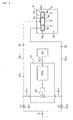
- Figure 2 is a basic block diagram of a pressure type division quantity controller FV.
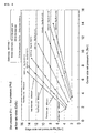
- Figure 3 is lines (computed values) to illustrate the relations between set pressure (Pl1 and Pl2) and a division flow rate ratio Q2/Q1 in the event that shower plated 3 and 4 to be used are made to be a
Pattern 1 with supply while dividing in Figure 1. - Figure 4 is lines (computed values) to illustrate the same relations in the event that
shower plates Pattern 2 as with Figure 3. - Figure 5 is an explanatory drawing to show a method for supplying processing gas to a chamber by using a conventional pressure type flow controller FCS.
- Figure 6 is an explanatory drawing to show the case wherein processing gas is supplied to a chamber C from a single gas supply source S by using a plurality of pressure type flow controllers.
- Figure 7 is an explanatory drawing to show the case wherein processing gas is supplied to a chamber C from a gas supply source equipped with a pressure type flow controller by using control valves.
-
- BL1· BL2
- Bypass lines
- C
- Chamber
- D
- Gas discharger
- Dc
- Gas discharger for the center part
- De
- Gas discharger for the edge part
- FV
- Pressure type division quantity controller
- GL1
- Branch supply line for the center part
- GL2
- Branch supply line for the edge part
- OV1 - OV2
- Open/close valves
- PT1·PT2
- Pressure in branch supply lines
- P
- Pressure inside a chamber
- PS1· PS2
- Pressure sensors of branch supply lines
- QCS
- Flow controller
- SV
- Electric switch valve
- 1
- Gas supply facility
- 2
- Division quantity controller
- 3
- Shower plate of a gas discharger for the center part
- 3a
- Orifice hole made in a shower plate
- 4
- Shower plate of a gas discharger for the edge part
- 4a
- Orifice hole made in a shower plate
- The embodiment in accordance with the present invention is described hereunder with reference to the drawings.
Figure 1 is an overall schematic diagram to explain a device and a method for supplying gas while dividing to a chamber from a gas supply facility equipped with a flow controller QCS according to the present invention. In Figure 1, agas supply facility 1 comprises a supply source S of processing gas G, a gas main valve Vo, a flow controller QCS and the like. Adivision quantity controller 2 comprises a pressure type division quantity controller FV, a communication control circuit CT and the like. - Further, in Figure 1, C designates a chamber, D a gas discharger, Dc a gas discharger for the center part, De a gas discharger for the edge part, GL1 a branch supply line for the center part, GL2 a branch supply line for the edge part, Q a total quantity of gas, Q1 · Q2 flow rates while dividing, PT1· PT2 pressure in branch supply lines GL1 and GL2, P3 pressure inside a chamber C, PS1 · PS2 pressure sensors of branch supply lines GL1 and GL2, 3 a shower plate of a gas discharger Dc for the center part, 3a an orifice hole made on the shower plate, 4 shower plate of a gas discharger De for the edge part, and 4a an orifice hole made on the shower plate.
- In addition, in Figure 1, EL1 · EL2 designate signal connection lines of a communication control circuit CT with pressure sensors PS1 and PS2, EL3 a signal connection line of a communication control circuit with an electric switch valve SV, and T1 a power source/signal input terminal.
- The afore-mentioned
gas supply facility 1 comprises a processing gas supply source S, a plurality of flow controllers QCS and the like. Any type flow controllers QCS can be employed as a flow controller QCS as long as it functions accurately and quickly. A pressure type flow controller FCS illustrated in the afore-shown Figure 5 has been used herewith for a flow controller QCS. When a specified flow rate setting signal Qs is inputted to a control unit (CPU), pressure P1 on the upstream side of an orifice L is regulated by a control valve CV so that a flow rate Q on the downstream side is automatically adjusted to the set flow rate Qs.
Also, a control flow rate output signal Qe corresponding to the adjusted flow rate is outputted from the control unit (CPU). If it is found that the deviation between the flow rate setting input signal Qs and the afore-mentioned control flow rate setting signal Qe exceeds the prescribed time, an input/output deviation abnormality signal is transmitted from the CPU (not illustrated in Figure 5) as stated later. - The afore-mentioned
division quantity controller 2 comprises a plural number of open/close valves OV1 and OV2, a pressure type division quantity controller FV, a communication control circuit CT to control these, an electric switch valve SV for opening and closing of OV1 and OV2,orifice plates - As shown in Figure 2, the afore-mentioned pressure type division quantity controller comprises a control valve CV, a driving control part (CPU) for the control valve CV and the like, to regulate the degree of opening of the control valve CV through the mediation of the driving unit part (CPU) with the control signal inputted CT through the line EL3 from the communication circuit CT.
With the embodiment in Figure 2, a piezo-driving stroke amplification type metal diaphragm valve is employed for a control valve CV of the afore-mentioned pressure type division quantity controller FV so that it is easily adaptable even when the flow rates Q1 and Q2 are large. - When processing gas G is supplied into a chamber C through
orifice holes shower plates orifice hole 3a of theorifice plate 3 for the center part.
Similarly, a division quantity Q2 is controlled with a formula Q2=C2Pl2 by Pl2 if the relationships Pl2 > 2P3 are maintained between pressure P3 inside a chamber C and pressure Pl2 on the upstream side of theorifice hole 4a of theshower plate 4 for the edge part, (where C1 and C2 are constants dependent on the cross-sectional areas of the orifice holes 3a and 4a, their shapes or gas temperature). - Referring to Figure 1, the afore-mentioned communication control circuit CT is provided with a power source/signal input terminal T1, and connected to a pressure type division quantity controller FV and an electric switch valve through the mediation of signal connection lines EL3 and EL4.
- An open/close valve OV is pneumatically operated. It is of a normal open type wherewith it is open under a state of driving air not being supplied, but both open/close valves OV1 and OV2 are normally being closed when a
division quantity controller 2 is in a state of halting. - When a starting signal, a total flow quantity Q, a desire flow rate ratio Q2/Q1, a combination pattern of
shower plates
A communication control circuit CT opens an open/close valve of the non-subject-to-control branch supply line while it closes an open/close valve of the subject-to-control branch supply line.
Further, a communication control circuit CT determines values Q1 and Q2 with given total flow quantity Q and flow rate ratio.[Table 1] Set Pressure Ratio - Subject-to-control Open/close valves operation command Set pressure ratio Pl2/Pl1 Subject-to-control Open/close valve operation command OV1 OV2 > 1 Pl1 Close Open = 1 NONE Open Open < 1 Pl2 Open Close - By inputting a specified signal to the communication control circuit CT, pressure PT on the subject-to-control branch supply line side is regulated with the pressure type quantity controller FV.
Namely, a communication control circuit CT starts comparing set values with actual pressure by the pressure signal measured and transmitted by a pressure sensor PS of the subject-to-control branch supply line, and a signal is transmitted to regulate the degree of opening of the division quantity controller FV so that the difference is reduced. Concretely, in the event that it is found with the comparison results that actual pressure is lower than set pressure, the degree of opening of the division quantity controller FV is made wider to raise pressure PT of the subject-to-control branch supply line. When the results of the comparison are found to be reverse, that is, actual pressure is higher than set pressure, the degree of opening of the division quantity controller FV is made narrower to lower pressure PT of the subject-to-control branch supply line. - Set pressure is determined beforehand by computation of the relationships of supply flow rates of shower plates with pressure.
The set pressure ratio is determined from the results of the computation based on the flow rate ratio Q2/Q1 supplied to branch supply lines GL1 and GL2 as shown in Table 2 and Table 3.[Table 2] [Set pressure ratio/Subject-to-control division quantity/Open/close valve operation command] to flow rate ratios PATTERN 1Flow rate ratio Q2/Q1 Set pressure ratio Pl2/Pl1 Subject-to-control division flow quantity Open/close valve operation command OV1 OV2 4/1 2.079 > 1 Pl1 Close Open 3/1 1.795 > 1 Pl1 Close Open 2/1 1.473 > 1 Pl1 Close Open 1/1 1.041 > 1 Pl1 Close Open 1/2 0.736 < 1 Pl2 Open Close 1/3 0.601 < 1 Pl2 Open Close 1/4 0.520 < 1 Pl2 Open Close [Table 3] [Set pressure ratio/Subject-to-control division quantity/Open/close valve operation command] to flow rate ratios PATTERN 2Flow rate ratio Q2/Q1 Set pressure ratio Pl2/Pl1 Subject-to-control division flow quantity Open/close valve operation command OV1 OV2 4/1 2.008 > 1 Pl1 Close Open 3/1 1.795 > 1 Pl1 Close Open 2/1 1.473 > 1 Pl1 Close Open 1/1 1.041 > 1 Pl1 Close Open 1/2 0.736 < 1 Pl2 Open Close 1/3 0.601 < 1 Pl2 Open Close 1/4 0.520 < 1 Pl2 Open Close - With the present embodiment, for shower plates (orifice plates) 3 and 4 of gas dischargers Dc and De, two sets of shower plate, that is, DC1 having 420
orifice holes 3a and Dc2 having 480orifice holes 3a are ready for the afore-mentionedshower plate 3 for the center part, and similarly another two sets of shower plate, that is, De1 having 360orifice holes 4a and De2 having 476orifice holes 4a are also ready for theshower plate 4 for the edge part. - Furthermore, the afore-mentioned flow rate ratio Q2/Q1 can be set at 1/1, 1/2, 1/3, 1/4, 2/1, 3/1 or 4/1. Set pressure computed on this (or set pressure specified by the gas supply chamber side) and set pressure ratio are inputted to the input terminal T1.
- As described later, set pressure and set pressure ratio listed in the above-shown Table 2 and Table 3 are determined by computing set pressure Pl1 and Pl2 on the upstream side of
orifice holes orifice holes shower plates - For combinations of the afore-mentioned
shower plates shower plate 3 having 420orifice holes 3a and ashower plate 4 having 360orifice holes 4a, and combination (hereinafter called Pattern 2) of ashower plate 3 having 480orifice holes 3a and ashower plate 4 having 476orifice holes 4a. - The relationship of the afore-mentioned division flow rates Q1 and Q2 and pressure Pl1 and Pl2 are formulated by using the following equations of conductance.
That is, the flow rate Q of gas passing through a pipe is expressed by Q=C x (P1 - P2) ... (1) and C=182 x D4 x (P1 + P2)/2 x 1/L ... (2), where C represents a conductance (Usec), D the diameter of a pipe (cm), L the length of a pipe (cm), P1 upstream pressure of a pipe (Torr), P2 downstream pressure of a pipe (Torr) and Q a flow rate (Torr· L/sec).
With the above equations (1) and (2), internal pressure (Pl1 and Pl2) on the upstream side of a shower plate is computed by using the outer diameter of the orifice hole of the shower plate as D, the length of the orifice hole of the shower plate as L, the internal pressure of a chamber (P3 =0.015Torr) as downstream side pressure P2, and a flow rate per an orifice hole as a flow rate Q respectively. - Figure 3 is numerical values shown as a graph illustrating the relationships, in the event (Pattern 1) that a
shower plate 3 of the gas discharger Dc for the center part having 420 orifice holes with an internal diameter of 0.2mm ϕ and ashower plate 4 of the gas discharger De for the edge part having 360 orifice holes with an internal diameter of 0.2mmϕare combined, of a total flow rate (a whole flow rate) Q, control pressure PT1 for the center part and control pressure PT2 for the edge part are computed making a flow rate ratio (E/C=Q2/Q1) as a parameter. For example, in case of Q=1600, 1200, 800, 400 and 100SCCM at Q2/Q1=1, the mean value of the ratio Pl2/Pl1 of control pressure Pl2 on the edge part side and control pressure Pl1 on the center part side becomes 1.041. - Similarly, Figure 4 is numerical values shown as a graph in the event (Pattern 2) that a
shower plate 3 for a gas discharger Dc for the center part having 480 orifice holes with an internal diameter of 0.2mmϕ and ashower plate 4 for a gas discharger De for the edge part having 476 orifice holes with an internal diameter are combined. For example, in case of Q=1600, 1200, 800, 400 and 100SCCM at Q2/Q1, the mean value of the ratio Pl2/Pl1 of control pressure Pl2 on the edge part side and control pressure Pl1 on the center part side becomes 1.001. - Table 2 and Table 3 illustrate all computed values that show the relationships of the flow rate ratio Q2/Q1 and the ratio Pl2/Pl1 of control pressure Pl2 on the edge part side and control pressure Pl1 on the center part side with
Pattern 1 andPattern 2 shown in Figure 3 and Figure 4. For example, Figure 3 shows that the ratio Pl2/Pl1 of control pressure Pl2 on the edge part side and control pressure Pl1, on the center part side becomes mathematically 1.041 in case that combination ofshower plates Pattern 1, and that the flow rate ratio Q2/Q1 is 1. - A method for supplying gas while dividing to a chamber according to the present invention is explained hereafter. Referring to Figure 1 and Figure 2, both open/close valves OV1 and OV2 are fully closed in case that a starting signal is not inputted to a communication control circuit CT.
- To supply a total quantity Q of gas while dividing at a specified ratio Q2/Q1 (for example, Q2/Q1=1/2), a total flow quantity Q, a combination pattern of
shower plates plates
Next, a subject-to-control flow while dividing and a non-subject-to-control flow while dividing are determined by a communication control circuit CT based on given total quantity Q, a flow rate ratio Q2/Q1 and set pressure Pl1 and Pl2. Then an open/close valve OV of a non-subject-to-control branch supply line is opened, while an open/close valve OV of a non-subject-to-control branch supply line is closed. - For example, upon receiving a signal indicating t total flow rate Q of 1200SCCM,
Pattern 1 of combination patterns ofshower plate - An open/close valve OV2 of the non-subject-to-control branch supply line GL2 is opened, while an open/close valve OV1 of the subject-to-control branch supply line GL1 is closed by the communication control circuit CT.
The communication control circuit CT compares set pressure Pl1 with actual pressure PT1 by the pressure signal measured and transmitted by the pressure sensor PS1 of the subject-to-control branch supply line GL1. - The communication control circuit CT compares set pressure Pl1 of a subject-to-control branch supply line GL1 with actual pressure PT1, to transmit a signal to regulate the degree of opening of a division quantity controller FV to reduce the difference.
Namely, in the event that comparison results found that actual pressure PT1 is lower than set pressure Pl1, the degree of opening of the division quantity controller FV is made wider to raise pressure of the subject-to-control branch supply line PL1. With the reverse results that actual pressure PT1 is higher than set pressure Pl1, the degree of opening of the division quantity controller FV is made narrower to lower pressure of the subject-to-control branch supply line PL1. - With the communication control circuit CT, set pressure Pl1 of the subject-to-control branch supply line GL1 and actual pressure are compared. When there is found no difference, or the difference is converged on the range of difference set in advance, the degree of opening of the division quantity controller FV is maintained, thus an automatic flow division control being completed.
Namely, a specified quantity Q of raw gas G from a gas supply source S is supplied to a wafer H into a chamber C through gas dischargers Dc and De while dividing at a specified flow rate ratio Q1/Q2. - Also, with the communication control circuit CT, set pressure Pl1 and actual pressure PT1 are compared. When there is found no difference, or the difference is converged on the range of difference set in advance, the degree of opening of the division quantity controller FV is maintained, thus an automatic flow division control being completed. However, in the event that actual pressure PT1 fluctuates due to temperature changes or any other reasons, and the difference with set pressure Pl1 comes to exceed the difference set in advance, a communication control circuit restarts to regulate the degree of opening of the division quantity controller FV.
- With the embodiment, it is so constituted that a starting signal, a total flow quantity Q, a desired flow rate ratio Q2/Q1, combination patterns of
shower plates - The present invention can be applied to facilities wherewith fluids are supplied while dividing under critical pressure conditions. For example, it can be utilized with a chamber in semiconductor manufacturing facilities or with a chamber in facilities for manufacturing chemical or pharmaceutical products.
Claims (9)
- A device for supplying gas while dividing to a chamber from a gas supply facility equipped with a flow controller characterized in that, with a device for supplying a specified quantity Q of gas G while dividing at a specified flow rate ratio Q1/Q2 from a gas supply facility 1 provided with a flow controller QCS into a chamber C through a plurality of branch supply lines GL1 and GL2 and shower plates 3 and 4 fixed to the ends thereof, open/close valves OV1 and OV2 are provided with an afore-mentioned plurality of branch supply lines GL1 and GL2 respectively, and also a bypass line BL1 on the downstream side of an open/close valve OV1 and branched from the branch supply line GL1, a bypass line BL2 on the downstream side of an open/close valve OV2 and branched from the branch supply line GL2, a pressure type division quantity controller FV connected to the afore-mentioned bypass lines BL1 and BL2, a pressure sensor PS1 to measure pressure inside the branch supply line GL1, and a pressure sensor PS2 to measure pressure inside the branch supply line GL2 are provided.
- A device for supplying gas while dividing to a chamber from a gas supply facility equipped with a flow controller as claimed in Claim 1 wherein a control device CT to regulate the degree of opening of a pressure type division quantity controller FV is provided to reduce the difference between actual pressure of the branch supply line and set pressure to reach the specified flow rate ratio Q1/Q2 by comparing either one of set pressure Pl1 or Pl2 of the branch supply lines GL1 and GL2 to reach the specified flow rate ratio Q1/Q2 with corresponding actual pressure PT1 or PT2 of the branch supply lines GL1 and GL2 measured by the pressure sensor PS1 or PS2.
- A device for supplying gas while dividing to a chamber from a gas supply facility equipped with a flow controller as claimed in Claim 1 or Claim 2 wherein an open/close valve OV1 and an open/close valve OV2 are pneumatically operated, and a switch valve SV is provided for supplying actuating air to the open/close valve OV1 and the open/close valve OV2.
- A device for supplying gas while dividing to a chamber from a gas supply facility equipped with a flow controller as claimed in Claim 1, Claim 2 or Claim 3 wherein an open/close valve OV1 and an open/close valve OV2 are made to be integrated.
- A device for supplying gas while dividing to a chamber from a gas supply facility equipped with a flow controller as claimed in Claim 1, Claim 2, Claim 3 or Claim 4 wherein a pressure type flow controller FCS is used for a flow controller QCS.
- A method for supplying gas while dividing to a chamber from a gas supply facility equipped with a flow controller characterized in that, with a method for supplying a specified quantity Q of gas G while dividing at a specified flow rate ratio Q1/Q2 from a gas supply facility 1 provided with a flow controller QCS into a chamber C through a plurality of branch supply lines GL1 and GL2 and shower plates 3 and 4 fixed to the ends thereof, open/close valves OV1 and OV2 are installed on an afore-mentioned plurality of branch supply lines GL1 and GL2 respectively, and also a bypass line BL1 on the downstream side of an open/close valve OV1 and branched from the branch supply line GL1 and a
bypass line BL2 on the downstream side of an open/close valve OV2 and branched from the branch supply line GL2, a pressure type division quantity controller FV connected to the afore-mentioned bypass lines BL1 and BL2, a pressure sensor PS1 to measure pressure inside the branch supply line GL1 and a pressure sensor PS2 to measure pressure inside the branch supply line GL2 are provided so that a total quantity Q=Q1+Q2 of gas is supplied while dividing into a chamber C at desired division quantities Q1 and Q2 by opening the open/close valve of the branch supply line which has a larger flow rate to regulate the degree of opening of the afore-mentioned pressure type division quantity controller FV, and adjusting the flow rate of the branch supply line which has the larger flow rate to the branch supply line which has the smaller flow rate, thus regulating pressure in the branch supply lines GL1 and GL2. - A method for supplying gas while dividing to a chamber from a gas supply facility equipped with a flow controller as claimed in Claim 6 wherein it is so made that the degree of opening of a pressure type division quantity controller FV is regulated to reduce the difference between actual pressure of a branch supply line and set pressure to reach a specified flow rate ratio Q1/Q2 by comparing either one of set pressure Pl1 or Pl2 of branch supply lines GL1 and GL2 to reach the specified flow rate ratio Q1/Q2 with corresponding actual pressure PT1 or PT2 of the branch supply lines GL1 and GL2 measured by the pressure sensor PS1 or the pressure sensor PS2.
- A device for supplying gas while dividing to a chamber from a gas supply facility equipped with a flow controller as claimed in Claim 6 or Claim 7 wherein it is so made that an open/close valve OV1 and an open/close valve OV2 are pneumatically operated, and a switch valve SV is provided for supplying actuating air to the open/close valve OV1 and the open/close valve OV2 so that the open/close valve of the branch supply line with the larger supply quantity is made open by the switch valve SV.
- A method for supplying gas while dividing to a chamber from a gas supply facility equipped a flow controller as claimed in Claim 6, Claim 7 or Claim 8 wherein it is so made that a pressure type flow controller is used for a flow controller QCS.
Applications Claiming Priority (2)
| Application Number | Priority Date | Filing Date | Title |
|---|---|---|---|
| JP2003177134A JP4195837B2 (en) | 2003-06-20 | 2003-06-20 | Gas diversion supply apparatus and gas diversion supply method |
| PCT/JP2004/008117 WO2004114038A1 (en) | 2003-06-20 | 2004-06-10 | Device for dividing and feeding gas flow from flow rate- regulating device-equipped gas-feeding equipment to chamber |
Publications (1)
| Publication Number | Publication Date |
|---|---|
| EP1637950A1 true EP1637950A1 (en) | 2006-03-22 |
Family
ID=33534922
Family Applications (1)
| Application Number | Title | Priority Date | Filing Date |
|---|---|---|---|
| EP20040745747 Withdrawn EP1637950A1 (en) | 2003-06-20 | 2004-06-10 | Device for dividing and feeding gas flow from flow rate- regulating device-equipped gas-feeding equipment to chamber |
Country Status (8)
| Country | Link |
|---|---|
| US (2) | US8496022B2 (en) |
| EP (1) | EP1637950A1 (en) |
| JP (1) | JP4195837B2 (en) |
| KR (1) | KR100710627B1 (en) |
| CN (1) | CN100538573C (en) |
| IL (1) | IL172055A0 (en) |
| TW (1) | TWI235902B (en) |
| WO (1) | WO2004114038A1 (en) |
Families Citing this family (50)
| Publication number | Priority date | Publication date | Assignee | Title |
|---|---|---|---|---|
| JP4550507B2 (en) * | 2004-07-26 | 2010-09-22 | 株式会社日立ハイテクノロジーズ | Plasma processing equipment |
| US7467027B2 (en) * | 2006-01-26 | 2008-12-16 | Mks Instruments, Inc. | Compensation for thermal siphoning in mass flow controllers |
| JP4814706B2 (en) | 2006-06-27 | 2011-11-16 | 株式会社フジキン | Flow ratio variable type fluid supply device |
| US20080216901A1 (en) * | 2007-03-06 | 2008-09-11 | Mks Instruments, Inc. | Pressure control for vacuum processing system |
| KR20110130535A (en) * | 2007-10-31 | 2011-12-05 | 도쿄엘렉트론가부시키가이샤 | Plasma Treatment System and Plasma Treatment Method |
| JP5054500B2 (en) * | 2007-12-11 | 2012-10-24 | 株式会社フジキン | Pressure-controlled flow standard |
| KR100943065B1 (en) * | 2008-03-25 | 2010-02-19 | 차상방 | Chemical feeder |
| CN101893164B (en) * | 2010-07-19 | 2013-03-06 | 中国航空工业集团公司西安飞机设计研究所 | Multi-branch small flow distribution method |
| WO2012016971A1 (en) | 2010-08-02 | 2012-02-09 | Basell Polyolefine Gmbh | Process and apparatus for mixing and splitting fluid streams |
| CN102278598B (en) * | 2011-05-04 | 2013-06-12 | 中国航空工业集团公司西安飞机设计研究所 | Large pipe network flow distribution experiment method |
| CN103177923B (en) * | 2011-12-20 | 2016-05-11 | 中微半导体设备(上海)有限公司 | A kind of gas distributed system and verification method that is applied to plasma treatment appts |
| JP5754853B2 (en) * | 2012-01-30 | 2015-07-29 | 株式会社フジキン | Gas shunt supply device for semiconductor manufacturing equipment |
| JP5881467B2 (en) | 2012-02-29 | 2016-03-09 | 株式会社フジキン | Gas diversion supply apparatus and gas diversion supply method using the same |
| JP5665794B2 (en) * | 2012-04-27 | 2015-02-04 | 株式会社フジキン | Gas shunt supply device for semiconductor manufacturing equipment |
| US9157535B2 (en) | 2012-11-30 | 2015-10-13 | Fluor Technologies Corporation | Positive isolation through isolation of air supply to pneumatic valves |
| US20140230910A1 (en) * | 2013-02-20 | 2014-08-21 | Agilent Technologies, Inc. | Split-channel gas flow control |
| US9454158B2 (en) | 2013-03-15 | 2016-09-27 | Bhushan Somani | Real time diagnostics for flow controller systems and methods |
| JP6193679B2 (en) * | 2013-08-30 | 2017-09-06 | 株式会社フジキン | Gas diversion supply apparatus and gas diversion supply method |
| DE102013226158A1 (en) * | 2013-12-17 | 2015-06-18 | Robert Bosch Gmbh | Adsorption chiller, arrangement and motor vehicle |
| CA2939175C (en) * | 2014-03-18 | 2022-02-15 | O.M.T. Officina Meccanica Tartarini S.R.L. | Apparatus and method for flow equipartition |
| US20150283523A1 (en) * | 2014-04-03 | 2015-10-08 | Waterous Company | Compressed air foam generation |
| US10658222B2 (en) | 2015-01-16 | 2020-05-19 | Lam Research Corporation | Moveable edge coupling ring for edge process control during semiconductor wafer processing |
| US10146233B2 (en) * | 2015-04-06 | 2018-12-04 | Horiba Stec, Co., Ltd. | Flow rate ratio control apparatus and program for flow rate ratio control apparatus |
| US10957561B2 (en) * | 2015-07-30 | 2021-03-23 | Lam Research Corporation | Gas delivery system |
| US10192751B2 (en) | 2015-10-15 | 2019-01-29 | Lam Research Corporation | Systems and methods for ultrahigh selective nitride etch |
| US10497542B2 (en) | 2016-01-04 | 2019-12-03 | Daniel T. Mudd | Flow control showerhead with integrated flow restrictors for improved gas delivery to a semiconductor process |
| US10825659B2 (en) | 2016-01-07 | 2020-11-03 | Lam Research Corporation | Substrate processing chamber including multiple gas injection points and dual injector |
| US10699878B2 (en) | 2016-02-12 | 2020-06-30 | Lam Research Corporation | Chamber member of a plasma source and pedestal with radially outward positioned lift pins for translation of a substrate c-ring |
| US10147588B2 (en) | 2016-02-12 | 2018-12-04 | Lam Research Corporation | System and method for increasing electron density levels in a plasma of a substrate processing system |
| US10651015B2 (en) | 2016-02-12 | 2020-05-12 | Lam Research Corporation | Variable depth edge ring for etch uniformity control |
| US10438833B2 (en) | 2016-02-16 | 2019-10-08 | Lam Research Corporation | Wafer lift ring system for wafer transfer |
| WO2017146558A1 (en) * | 2016-02-23 | 2017-08-31 | Electro Controles Del Noroeste S.A. De C.V. | Modular fluid-dosing system and method therefor |
| CN108885471B (en) * | 2016-03-29 | 2021-10-01 | 株式会社富士金 | Pressure type flow control device and flow self-diagnosis method |
| US10410832B2 (en) | 2016-08-19 | 2019-09-10 | Lam Research Corporation | Control of on-wafer CD uniformity with movable edge ring and gas injection adjustment |
| JP6626800B2 (en) | 2016-08-19 | 2019-12-25 | 東京エレクトロン株式会社 | Method for inspecting shower plate of plasma processing apparatus |
| US10983538B2 (en) | 2017-02-27 | 2021-04-20 | Flow Devices And Systems Inc. | Systems and methods for flow sensor back pressure adjustment for mass flow controller |
| CN118380374A (en) | 2017-11-21 | 2024-07-23 | 朗姆研究公司 | Bottom edge ring and middle edge ring |
| WO2019199641A1 (en) * | 2018-04-12 | 2019-10-17 | Lam Research Corporation | Determining and controlling substrate temperature during substrate processing |
| JP7044629B2 (en) * | 2018-05-18 | 2022-03-30 | 株式会社堀場エステック | Fluid control device and flow rate control device |
| JP7068062B2 (en) * | 2018-06-18 | 2022-05-16 | 株式会社堀場製作所 | Fluid control device and flow rate control device |
| JP6859426B2 (en) | 2018-08-13 | 2021-04-14 | ラム リサーチ コーポレーションLam Research Corporation | Replaceable and / or foldable edge ring assembly for plasma sheath adjustment incorporating edge ring positioning and centering mechanism |
| CN110410672B (en) * | 2019-07-05 | 2021-08-10 | 中国科学院空间应用工程与技术中心 | Nitrogen supply method and device |
| JP7226222B2 (en) * | 2019-09-24 | 2023-02-21 | 東京エレクトロン株式会社 | Gas supply device and gas supply method |
| KR20260010464A (en) | 2020-03-23 | 2026-01-20 | 램 리써치 코포레이션 | Mid-ring erosion compensation in substrate processing systems |
| KR102512970B1 (en) * | 2020-03-26 | 2023-03-22 | 주식회사 클레버 | Degas apparatus of battery cell |
| WO2022076227A1 (en) | 2020-10-05 | 2022-04-14 | Lam Research Corporation | Moveable edge rings for plasma processing systems |
| CN112169584A (en) * | 2020-10-09 | 2021-01-05 | 山东国舜建设集团有限公司 | Device and method for controlling ammonia water flow in denitration system |
| US12523380B2 (en) | 2021-08-16 | 2026-01-13 | Applied Materials, Inc. | Prevention of contamination of substrates during pressure changes in processing systems |
| KR20240028609A (en) * | 2022-08-25 | 2024-03-05 | 주식회사 원익아이피에스 | Substrate processing appartus and gas supply method |
| CN116677920A (en) * | 2023-05-08 | 2023-09-01 | 上海引万光电科技有限公司 | Multi-path gas distribution method and equipment |
Family Cites Families (19)
| Publication number | Priority date | Publication date | Assignee | Title |
|---|---|---|---|---|
| US2961829A (en) * | 1959-10-15 | 1960-11-29 | New York Air Brake Co | Hydraulic transmission |
| US4980204A (en) * | 1987-11-27 | 1990-12-25 | Fujitsu Limited | Metal organic chemical vapor deposition method with controlled gas flow rate |
| EP0370150A1 (en) * | 1988-11-21 | 1990-05-30 | L'air Liquide, Societe Anonyme Pour L'etude Et L'exploitation Des Procedes Georges Claude | Process for producing standard gas mixture and apparatus for producing the same |
| GB9021094D0 (en) * | 1990-09-27 | 1990-11-07 | Oxford Glycosystems Ltd | Liquid delivery systems |
| DE4126846C1 (en) * | 1991-08-14 | 1993-02-25 | Danfoss A/S, Nordborg, Dk | |
| US5453124A (en) * | 1992-12-30 | 1995-09-26 | Texas Instruments Incorporated | Programmable multizone gas injector for single-wafer semiconductor processing equipment |
| US5647945A (en) * | 1993-08-25 | 1997-07-15 | Tokyo Electron Limited | Vacuum processing apparatus |
| JP3291161B2 (en) * | 1995-06-12 | 2002-06-10 | 株式会社フジキン | Pressure type flow controller |
| TW342429B (en) * | 1995-07-14 | 1998-10-11 | Tadahiro Omi | Fluid control system and valve used in it |
| US5865205A (en) * | 1997-04-17 | 1999-02-02 | Applied Materials, Inc. | Dynamic gas flow controller |
| JP3586075B2 (en) * | 1997-08-15 | 2004-11-10 | 忠弘 大見 | Pressure type flow controller |
| JPH11265218A (en) | 1998-03-18 | 1999-09-28 | Kokusai Electric Co Ltd | Automatic flow rate / flow rate ratio conversion data calibration device and gas supply device |
| JP2000286267A (en) * | 1999-03-31 | 2000-10-13 | Tokyo Electron Ltd | Heat treatment method |
| JP2002161086A (en) | 2000-09-13 | 2002-06-04 | Sankyo Co Ltd | Zofimarin derivative having oxazepane ring |
| JP2002110570A (en) * | 2000-10-04 | 2002-04-12 | Asm Japan Kk | Gas line system for semiconductor manufacturing apparatus |
| US6418954B1 (en) * | 2001-04-17 | 2002-07-16 | Mks Instruments, Inc. | System and method for dividing flow |
| JP2002339071A (en) * | 2001-05-18 | 2002-11-27 | L'air Liquide Sa Pour L'etude & L'exploitation Des Procede S Georges Claude | Treating-gas feed mechanism in alcvd system |
| JP2003323218A (en) * | 2002-05-02 | 2003-11-14 | Nippon M K S Kk | Flow ratio control device |
| JP3856730B2 (en) * | 2002-06-03 | 2006-12-13 | 東京エレクトロン株式会社 | A gas diversion supply method to a chamber from a gas supply facility provided with a flow rate control device. |
-
2003
- 2003-06-20 JP JP2003177134A patent/JP4195837B2/en not_active Expired - Fee Related
-
2004
- 2004-05-21 TW TW93114510A patent/TWI235902B/en not_active IP Right Cessation
- 2004-06-10 EP EP20040745747 patent/EP1637950A1/en not_active Withdrawn
- 2004-06-10 WO PCT/JP2004/008117 patent/WO2004114038A1/en not_active Ceased
- 2004-06-10 CN CNB2004800172962A patent/CN100538573C/en not_active Expired - Fee Related
- 2004-06-10 US US10/561,514 patent/US8496022B2/en not_active Expired - Fee Related
- 2004-06-10 KR KR1020057020342A patent/KR100710627B1/en not_active Expired - Fee Related
-
2005
- 2005-11-20 IL IL172055A patent/IL172055A0/en unknown
-
2013
- 2013-06-26 US US13/927,786 patent/US9098082B2/en not_active Expired - Fee Related
Non-Patent Citations (1)
| Title |
|---|
| See references of WO2004114038A1 * |
Also Published As
| Publication number | Publication date |
|---|---|
| US20110094596A1 (en) | 2011-04-28 |
| KR100710627B1 (en) | 2007-04-24 |
| US9098082B2 (en) | 2015-08-04 |
| JP2005011258A (en) | 2005-01-13 |
| CN1809794A (en) | 2006-07-26 |
| CN100538573C (en) | 2009-09-09 |
| KR20060023961A (en) | 2006-03-15 |
| WO2004114038A1 (en) | 2004-12-29 |
| US20130340837A1 (en) | 2013-12-26 |
| TWI235902B (en) | 2005-07-11 |
| TW200506569A (en) | 2005-02-16 |
| IL172055A0 (en) | 2009-02-11 |
| JP4195837B2 (en) | 2008-12-17 |
| US8496022B2 (en) | 2013-07-30 |
Similar Documents
| Publication | Publication Date | Title |
|---|---|---|
| US8496022B2 (en) | Device and method for supplying gas while dividing to chamber from gas supplying facility equipped with flow controller | |
| KR100556195B1 (en) | Gas fractionation supply method to the chamber from a gas supply facility having a flow control device | |
| US7798167B2 (en) | Internal pressure controller of chamber and internal pressure subject-to-control type chamber | |
| US8418714B2 (en) | Flow rate range variable type flow rate control apparatus | |
| EP2034379A1 (en) | Variable flow rate ratio type fluid supply device | |
| KR20020000867A (en) | Wide range gas flow system with real time flow measurement and correction | |
| US10386863B2 (en) | Pressure-type flow controller | |
| US7594517B2 (en) | Gas supply facility of a chamber and a method for an internal pressure control of the chamber for which the facility is employed | |
| US9921089B2 (en) | Flow rate range variable type flow rate control apparatus | |
| US20160109886A1 (en) | Flow rate range variable type flow rate control apparatus | |
| CN100517626C (en) | Vacuum device, its leak rate measurement method, measurement program and storage medium | |
| US20050097730A1 (en) | Semiconductor manufacturing apparatus | |
| US20230229177A1 (en) | Fluid control device, fluid control method, and fluid control program | |
| KR101173571B1 (en) | Vacuum pumping system of substrate processing apparatus and method of vacuum pumping transfer chamber using the same | |
| KR100968563B1 (en) | Automatic pressure control method of plasma etching device | |
| US20250264891A1 (en) | Flow ratio controllers and gas distribution systems utilizing flow ratio controllers | |
| TW202605892A (en) | Double-cavity processing system and gas supply method | |
| KR20180050610A (en) | Liquid flow rate control system | |
| KR20030096488A (en) | Chamber Pressure Ajusting Assembly |
Legal Events
| Date | Code | Title | Description |
|---|---|---|---|
| PUAI | Public reference made under article 153(3) epc to a published international application that has entered the european phase |
Free format text: ORIGINAL CODE: 0009012 |
|
| 17P | Request for examination filed |
Effective date: 20051205 |
|
| AK | Designated contracting states |
Kind code of ref document: A1 Designated state(s): CH DE FR GB IT LI NL |
|
| DAX | Request for extension of the european patent (deleted) | ||
| RBV | Designated contracting states (corrected) |
Designated state(s): CH DE FR GB IT LI NL |
|
| STAA | Information on the status of an ep patent application or granted ep patent |
Free format text: STATUS: THE APPLICATION HAS BEEN WITHDRAWN |
|
| 18W | Application withdrawn |
Effective date: 20100518 |