EP1637781A1 - Procede d'assemblage a joint et joint a cet effet - Google Patents
Procede d'assemblage a joint et joint a cet effet Download PDFInfo
- Publication number
- EP1637781A1 EP1637781A1 EP04745743A EP04745743A EP1637781A1 EP 1637781 A1 EP1637781 A1 EP 1637781A1 EP 04745743 A EP04745743 A EP 04745743A EP 04745743 A EP04745743 A EP 04745743A EP 1637781 A1 EP1637781 A1 EP 1637781A1
- Authority
- EP
- European Patent Office
- Prior art keywords
- gasket
- intake manifold
- throttle body
- fitting groove
- confronting
- Prior art date
- Legal status (The legal status is an assumption and is not a legal conclusion. Google has not performed a legal analysis and makes no representation as to the accuracy of the status listed.)
- Withdrawn
Links
Images


Classifications
-
- F—MECHANICAL ENGINEERING; LIGHTING; HEATING; WEAPONS; BLASTING
- F02—COMBUSTION ENGINES; HOT-GAS OR COMBUSTION-PRODUCT ENGINE PLANTS
- F02M—SUPPLYING COMBUSTION ENGINES IN GENERAL WITH COMBUSTIBLE MIXTURES OR CONSTITUENTS THEREOF
- F02M35/00—Combustion-air cleaners, air intakes, intake silencers, or induction systems specially adapted for, or arranged on, internal-combustion engines
- F02M35/10—Air intakes; Induction systems
- F02M35/10242—Devices or means connected to or integrated into air intakes; Air intakes combined with other engine or vehicle parts
- F02M35/10255—Arrangements of valves; Multi-way valves
-
- F—MECHANICAL ENGINEERING; LIGHTING; HEATING; WEAPONS; BLASTING
- F02—COMBUSTION ENGINES; HOT-GAS OR COMBUSTION-PRODUCT ENGINE PLANTS
- F02D—CONTROLLING COMBUSTION ENGINES
- F02D9/00—Controlling engines by throttling air or fuel-and-air induction conduits or exhaust conduits
- F02D9/08—Throttle valves specially adapted therefor; Arrangements of such valves in conduits
- F02D9/10—Throttle valves specially adapted therefor; Arrangements of such valves in conduits having pivotally-mounted flaps
- F02D9/1035—Details of the valve housing
-
- F—MECHANICAL ENGINEERING; LIGHTING; HEATING; WEAPONS; BLASTING
- F02—COMBUSTION ENGINES; HOT-GAS OR COMBUSTION-PRODUCT ENGINE PLANTS
- F02M—SUPPLYING COMBUSTION ENGINES IN GENERAL WITH COMBUSTIBLE MIXTURES OR CONSTITUENTS THEREOF
- F02M35/00—Combustion-air cleaners, air intakes, intake silencers, or induction systems specially adapted for, or arranged on, internal-combustion engines
- F02M35/10—Air intakes; Induction systems
- F02M35/10091—Air intakes; Induction systems characterised by details of intake ducts: shapes; connections; arrangements
- F02M35/10144—Connections of intake ducts to each other or to another device
-
- F—MECHANICAL ENGINEERING; LIGHTING; HEATING; WEAPONS; BLASTING
- F16—ENGINEERING ELEMENTS AND UNITS; GENERAL MEASURES FOR PRODUCING AND MAINTAINING EFFECTIVE FUNCTIONING OF MACHINES OR INSTALLATIONS; THERMAL INSULATION IN GENERAL
- F16J—PISTONS; CYLINDERS; SEALINGS
- F16J15/00—Sealings
- F16J15/02—Sealings between relatively-stationary surfaces
- F16J15/021—Sealings between relatively-stationary surfaces with elastic packing
- F16J15/022—Sealings between relatively-stationary surfaces with elastic packing characterised by structure or material
- F16J15/024—Sealings between relatively-stationary surfaces with elastic packing characterised by structure or material the packing being locally weakened in order to increase elasticity
- F16J15/025—Sealings between relatively-stationary surfaces with elastic packing characterised by structure or material the packing being locally weakened in order to increase elasticity and with at least one flexible lip
-
- F—MECHANICAL ENGINEERING; LIGHTING; HEATING; WEAPONS; BLASTING
- F16—ENGINEERING ELEMENTS AND UNITS; GENERAL MEASURES FOR PRODUCING AND MAINTAINING EFFECTIVE FUNCTIONING OF MACHINES OR INSTALLATIONS; THERMAL INSULATION IN GENERAL
- F16J—PISTONS; CYLINDERS; SEALINGS
- F16J15/00—Sealings
- F16J15/02—Sealings between relatively-stationary surfaces
- F16J15/06—Sealings between relatively-stationary surfaces with solid packing compressed between sealing surfaces
- F16J15/062—Sealings between relatively-stationary surfaces with solid packing compressed between sealing surfaces characterised by the geometry of the seat
Definitions
- the present invention relates to a gasket assembling method, and a gasket.
- the gasket has been used with a view to preventing leakage of a fluid (e.g., air) from the outside.
- a fluid e.g., air
- this seal is made by forming a fitting groove in one member and by fitting the gasket in the fitting groove thereby to hold the gasket in close contact with the groove bottom of the fitting groove and the surface of the other member.
- the gasket is made of a rubbery elastomer having a section of a convex, diamond or elliptical shape or a shape of a combination of irregularities.
- the other member, with which the gasket makes contact may be made of a resin.
- This member molded of the resin may have a waving or creep, may be short of strength or may fail to have an accurate flatness.
- the compression direction to compress the gasket disperses in size, or the compression force to compress the gasket may also disperse.
- the gasket has a shape of slender section.
- a throttle body having a section of a generally trapezoidal shape may be fitted in the intake manifold.
- the gasket is fitted in the fitting groove formed in the throttle body, and the throttle body having the gasket fitted therein is fitted in the intake manifold.
- Fig. 8 is a diagram for explaining the assembly of a throttle body 200 having a gasket 100 fitted therein, and an intake manifold 300.
- the assembly of the gasket is so performed after the gasket was fitted in the fitting groove, that the cover closes downward generally vertically.
- a fall may also occur to cause a bite (in an area X, as shown in Fig. 9) even in a gasket 110 such as the Patent Document 1, as shown in Fig. 9.
- the intake manifold 300 is assembled obliquely relative to the gasket 100 fitted in the throttle body 200, the squeeze of the gasket 100 and the corner portion 302 at the leading end of the intake manifold 300 may interfere to cause problems of a fall or torsion of the gasket or a bite into the groove.
- the surface pressure is made short by the short squeeze thereby to invite a reduction in the sealing performance.
- the present invention has been conceived to solve the aforementioned problems of the prior art thus far described and has an object to provide a gasket assembling method and a gasket, in which the sealing performance is stabilized by preventing the fall or bite of the gasket for sealing the clearance between the throttle body and the intake manifold to be assembled obliquely relative to each other.
- the present invention adopts the following means.
- the gasket is fitted in the fitting groove formed in the face of one of two members having faces confronting each other, and the two members are then assembled such that a corner portion of the other member does not contact with the gasket, whereby the gasket is assembled.
- the two members are assembled by first bringing the gasket in a fitting groove formed in one member into contact with only the close contact face (or the confronting face) of the other member, with which the gasket in the fitting groove makes close contact in the assembled state, and by bringing the gasket into sliding contact with the close contact face.
- the gasket to be fitted in the fitting groove of one member has a section of a generally pentagonal shape.
- This shape means the pentagonal section, which is composed of three points (i.e., the leading end and the end portions of the individual inclined faces) protruding to the side of the other member and forming a section of an angle shape having a round shape at the leading end, and two points determined by the bottom face (i.e., the end portions of the bottom face) to contact in planar with the groove bottom of the fitting groove.
- the assembly of the two members is performed such that the leading ends of the two inclined faces of the gasket make contact only with the close contact face of the other member.
- the corner portion of the generally pentagonal section which is located at the end portion of the two inclined faces on the downstream side in the direction of the relative movement of the other member to one member, and the side face between said corner portion and the bottom face make close contact with the groove side wall of the fitting groove confronting the corner portion.
- the corner portion of the other member does not contact with the gasket so that the gasket can be prevented from the fall or torsion by the interference with the corner portion.
- the surface pressure for the gasket to receive from the close contact face of the other member can be made substantially homogeneous without being influenced by the contact angle relative to the close contact face.
- the gasket is subject to the force in the direction for the other member to move relative to one member.
- the corner portion on the downstream side in the direction for the relative movement of the other member, and the side face between the corner portion and the bottom face make close contact with the groove side wall of the fitting groove 21 (especially, make planar contact with the groove side wall on the side face), and the bottom face of the gasket make planar contact with the groove bottom of the fitting groove so that the gasket can be prevented from turning.
- a method for assembling a gasket which is fitted in a fitting groove formed in the face of one of two members having faces confronting each other and is compressed, when the two members are assembled as their faces approach each other obliquely with respect to their confronting direction, thereby to seal the clearance between the two members, and which is formed into a generally pentagonal shape having two inclined faces forming a section of an angle shape protruding to the other of the two members and forming a leading end of a round section, and a bottom face for making planar contact with the groove bottom of the fitting groove, characterized by comprising:
- a gasket fitted in a fitting groove formed in the face of one of two members having confronting faces confronting each other and is compressed, when said two members are assembled as their confronting faces approach each other obliquely with respect to their confronting direction, thereby to seal the clearance between said two members, characterized:
- the present invention can be suitably applied especially to the case of the internal combustion engine such as an automobile, in which the gasket is assembled by fitting the gasket in the fitting groove formed in the throttle body (i.e., one member) and subsequently by assembling (or fitting) the throttle body in the intake manifold (i.e., the other member) such that the corner portion of the intake manifold does not contact with the gasket.
- a method for assembling a gasket which is fitted in a fitting groove formed in the face of a throttle body of the throttle body and an intake manifold having faces confronting each other and, is compressed when the throttle body and the intake manifold are assembled as their faces approach each other obliquely with respect to their confronting direction, thereby to seal the clearance between the throttle body and the intake manifold, and which is formed into a generally pentagonal shape having two inclined faces forming a section of an angle shape protruding to the side of the intake manifold and forming a leading end of a round section, and a bottom face for making planar contact with the groove bottom of said fitting groove, characterized by comprising:
- a gasket fitted in a fitting groove formed in the confronting face of a throttle body of the throttle body and an intake manifold having confronting faces confronting each other and, compressed when the throttle body and the intake manifold are assembled as their confronting faces approach each other obliquely with respect to their confronting direction, thereby to seal the clearance between the throttle body and the intake manifold, characterized:
- the gasket body is fitted in said fitting groove, and the assembly of the throttle body and the intake manifold begins with the contact between said leading end of said two inclined faces of the gasket body fitted in said fitting groove and said confronting face of the intake manifold, and then the throttle body and the intake manifold approach each other, while said leading end of said two inclined faces of the gasket body fitted in said fitting groove making sliding contact with only said confronting face of the intake manifold.
- the shape, as taken from the side of the intake manifold, of the gasket body fitted in said fitting groove is an elliptical shape having a longer axial direction in the assembly direction, in which the throttle body and the intake manifold are assembled.
- the gasket can be reduced in its portion generally perpendicular to the assembling direction of the throttle body and the intake manifold. Due to this portion, the gasket may fall when the throttle body and the intake manifold are assembled. In other words, the fall of the gasket can be prevented by reducing that portion.
- the assembly of the gasket means that the gasket is assembled between the throttle body and the intake manifold, and that the throttle body and the intake manifold are assembled in the state where the gasket is fitted in the fitting groove of the throttle body.
- the fall or bite of the gasket can be prevented to stabilize the sealing performance.
- Fig. 1 presenting diagrams for explaining the assembly of a throttle body 20 having a fitting groove 21 formed therein for fitting a gasket 1 according to this embodiment, and an intake manifold 30,
- Fig. 1A is a diagram showing the state before the assembly
- Fig. 1B is a diagram showing the state after the assembly.
- Fig. 2 is a diagram showing the fitting groove 21 formed in the throttle body 20.
- a section A - A shown in Fig. 2 corresponds to the throttle body 20 shown in Fig. 1.
- Fig. 3 is a schematic section showing the gasket 1 according to the embodiment of the present invention, and shows the state, in which the gasket 1 is fitted in the fitting groove 21 formed in the throttle body 20, and the state before the throttle body 20 and the intake manifold 30 are assembled.
- Fig. 3 is a diagram corresponding to an F portion shown in Fig. 1A.
- Fig. 4 is a schematic section showing the state, in which the gasket 1 is fitted in the fitting groove 21, and the state, in which the throttle body 20 and the intake manifold 30 are assembled.
- the gasket 1 according to the present embodiment is fitted in the fitting groove 21 which is formed in the throttle body 20 having a section of a generally trapezoidal shape, and seal faces are formed on this fitting groove 21 and on the close contact face (or opposed face) 31, as confronts the fitting groove 21, of the intake manifold 30 thereby to seal the clearance between the throttle body 20 and the intake manifold 30.
- the assembly of the throttle body 20 and the intake manifold 30 is performed such that the face of the throttle body 20 on which the fitting groove 21 is formed and the close contact face 31 of the intake manifold 30 move obliquely relative to each other, that is, the confronting faces of the throttle body 20 and the intake manifold 30 approach in oblique directions with respect to the confronting direction.
- the fitting groove 21 formed in the throttle body 20 is composed of a groove bottom 22, a groove side wall 23 on the B side and a groove side wall 24 on the A side.
- the gasket 1 according to the present embodiment is made of a rubbery elastomer into a generally pentagonal section.
- the gasket 1 is equipped with a bottom face 2 to abut against the groove bottom 22, a side wall 3 to confront the groove side wall 23, a side wall 4 to confront the groove side wall 24, and inclined faces 5 and 6 having a generally angle-shaped section for confronting the intake manifold 30 and for forming a leading end 8 having a generally pentagonal section. Moreover, the gasket 1 is formed at its leading end 8 into a chamfered round shape (or curved shape) between the inclined faces 5 and 6.
- the gasket 1 is so fitted in the fitting groove 21 of the throttle body 20 that its bottom face 2 comes into contact with the groove bottom 22 of the throttle body 20.
- the throttle body 20 is moved in the arrow D direction from the B side relative to the intake manifold 30 (as referred to Figs. 1 and 3).
- the throttle body 20 is so moved and fitted in the intake manifold 30 that the corner portion 32 of the intake manifold 30 may not contact with the gasket 1 (i.e., may not take the state, as indicated by double-dotted lines in Fig. 3).
- the throttle body 20 is so moved to bring the leading end 8 into contact with the close contact face 31 that the close contact face 31 of the intake manifold 30 may contact with the gasket 1 fitted in the throttle body 20, especially with the leading end 8 .
- the throttle body 20 is moved while sliding the leading end 8 on the close contact face 31 so as to keep the contacting state, thereby to insert the throttle body 20 into the intake manifold 30.
- an air passage of the intake manifold 30 through the throttle body 20 is formed, as indicated by arrow E in Fig. 1A.
- the corner portion 32 of the intake manifold 30 does not contact with the gasket 1 so that the gasket 1 can be prevented from fall or torsion by the interference with the corner portion 32.
- the leading end 8 is chamfered into the round shape, moreover, in the course of the throttle body 20 being fitted in the intake manifold 30, the surface pressure for the gasket 1 to receive from the close contact face 31 of the intake manifold 30 can be made substantially homogeneous without being influenced by the contact angle between the gasket 1 and the close contact face 31.
- the gasket 1 fitted in the fitting groove 21 is subject to the force, by which it is compressed in the direction of arrow C, when the throttle body 20 is fitted in the intake manifold 30.
- the gasket 1 is subject to a force, by which the side wall 3 is felled on the groove side wall 23 of the fitting groove 21.
- the side wall 3 comes into planar contact with the groove side wall 23, and the side wall 3 and the corner portion 7 of the inclined face 5 come into close contact with the groove side wall 23 so that the gasket 1 can be prevented from falling or turning.
- the bottom face 2 makes planar contact with the groove bottom 22, and the gasket 1 is subject to the force, by which it is compressed in the direction of arrow C. As a result, the bottom face 2 comes close contact with the groove bottom 22 so that the gasket 1 can be prevented from turning.
- leading end 8 is formed by the inclined faces 5 and 6 forming the shape of an angle shape so that the torsion is hard to occur even in case the leading end 8 comes into sliding close contact with the close contact face 31.
- the side wall 3 and the corner portion 7 make close contact with the groove side wall 23, and the bottom face 2 makes close contact with the groove bottom 22 without any serious torsion in the gasket 1 (especially, its portion having the inclined faces 5 and 6), whereby the gasket 1 can be prevented from falling or turning. Therefore, the gasket 1 (especially, its portion having the inclined faces 5 and 6) can be prevented from biting into the clearance between the throttle body 20 and the intake manifold 30.
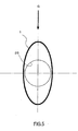
- Fig. 5 is a schematic diagram (i.e., a side view of the fitting groove 21 shown in Fig. 2), in which the gasket 1 fitted in the fitting groove 21 is seen from the side of the intake manifold 30, and shows the state, in which the gasket 1 is fitted in the fitting groove 21 in the outer periphery of a throttle bore 25 formed in the throttle body 20.
- arrow G indicates the assembling direction, in which the throttle body 20 and the intake manifold 30 are relatively,assembled.
- the gasket 1 is preferred to have an elliptical shape having a longer axial direction in the assembling direction G.
- the gasket 1 can be reduced in its portion generally perpendicular to the assembling direction of the throttle body 20 and the intake manifold 30. At this portion, the gasket 1 may fall when the throttle body 20 and the intake manifold 30 are assembled. In other words, the fall of the gasket 1 can be prevented by reducing that portion.
- the gasket 1 may be formed into either such an elliptical shape as is formed to have the direction of the longer axis in the assembling direction G after the gasket itself was formed, or such an elliptical shape that the gasket is fitted in the fitting groove 21 formed into the elliptical shape with the assembling direction G being in the longer axial direction.
- Fig. 6 presents diagrams for explaining another example of the assembly of the throttle body 20 and the intake manifold 30.
- Fig. 6A is a diagram showing the state before the assembly
- Fig. 6B is a diagram showing the state after the assembly.
- the center K of the throttle bore 25 of the throttle body 20 is displaced downstream of the assembling direction (i.e., the direction (of arrow D), in which the throttle body 20 moves relative to the intake manifold 30) with respect to the center J of the intake passage 33 of the intake manifold 30.
- the interference between the gasket 1 and the corner portion 32 of the intake manifold 30 depends upon the relation between the width H of the corner portion 32 of the intake manifold 30, with which the gasket 1 may interfere at the assembling time, and the width of the portion, where the gasket 1 is disposed, of the throttle body 20.
- the width H can be made larger than that of the case of Fig. 1 (as shown by a dotted line in Fig. 6A) (as the width of the corner portion 32 of the case shown in Fig. 1 is indicated by I). Therefore, the assembly can be performed such that the corner portion 32 of the intake manifold 30 does not interfere with the gasket 1.
- the throttle body 20 and the intake manifold 30 can be assembled without any fall or torsion of the gasket 1.
- the fitting groove 21 is so formed into the tapering shape as to make efficient the workability at the gasket fitting time, and the portion of the gasket 1, which is disposed in the fitting groove, is also shaped to follow the fitting groove 21 substantially.
- the shape should not be limited thereto, but, for example as shown in Fig. 7 the fitting groove 21 may be formed to have a generally rectangular section, or the portion of the gasket 1 to be formed in the fitting groove may also be formed to have a generally rectangular section following the fitting groove substantially.
- the gasket assembling method and the gasket according to the present invention are useful for sealing the clearance between two members having confronting faces, and are suitable especially for sealing the clearance between the throttle body and the intake manifold.
Applications Claiming Priority (2)
| Application Number | Priority Date | Filing Date | Title |
|---|---|---|---|
| JP2003168303A JP2005003130A (ja) | 2003-06-12 | 2003-06-12 | ガスケットの組付け方法及びガスケット |
| PCT/JP2004/008113 WO2004111505A1 (fr) | 2003-06-12 | 2004-06-10 | Procede d'assemblage a joint et joint a cet effet |
Publications (2)
| Publication Number | Publication Date |
|---|---|
| EP1637781A1 true EP1637781A1 (fr) | 2006-03-22 |
| EP1637781A4 EP1637781A4 (fr) | 2007-09-05 |
Family
ID=33549331
Family Applications (1)
| Application Number | Title | Priority Date | Filing Date |
|---|---|---|---|
| EP04745743A Withdrawn EP1637781A4 (fr) | 2003-06-12 | 2004-06-10 | Procede d'assemblage a joint et joint a cet effet |
Country Status (4)
| Country | Link |
|---|---|
| US (1) | US20060226610A1 (fr) |
| EP (1) | EP1637781A4 (fr) |
| JP (1) | JP2005003130A (fr) |
| WO (1) | WO2004111505A1 (fr) |
Cited By (3)
| Publication number | Priority date | Publication date | Assignee | Title |
|---|---|---|---|---|
| WO2011147900A3 (fr) * | 2010-05-28 | 2012-06-28 | BSH Bosch und Siemens Hausgeräte GmbH | Système de scellement et appareil électroménager doté de ce système |
| FR3042250A1 (fr) * | 2015-10-12 | 2017-04-14 | Joint Francais | Joint a section constante |
| CN107110361A (zh) * | 2015-01-08 | 2017-08-29 | 株式会社理研 | 密封圈 |
Families Citing this family (3)
| Publication number | Priority date | Publication date | Assignee | Title |
|---|---|---|---|---|
| JP5434681B2 (ja) * | 2010-03-02 | 2014-03-05 | Nok株式会社 | ガスケット及び密封構造 |
| JP5636579B2 (ja) * | 2010-06-17 | 2014-12-10 | 内山工業株式会社 | ガスケット |
| CN103649606A (zh) * | 2011-07-04 | 2014-03-19 | 株式会社三国 | 垫圈和节气门体 |
Citations (5)
| Publication number | Priority date | Publication date | Assignee | Title |
|---|---|---|---|---|
| GB655467A (en) * | 1947-02-21 | 1951-07-25 | Siam | Improvements in or relating to packings for pistons and the like |
| US4828274A (en) * | 1987-12-14 | 1989-05-09 | U.S. Foundry & Manufacturing Corp. | Sealing assembly for manhole covers and adjustment rings therefor |
| JPH09222169A (ja) * | 1996-02-15 | 1997-08-26 | Uchiyama Mfg Corp | 油圧シール |
| JPH10103089A (ja) * | 1996-09-25 | 1998-04-21 | Aisan Ind Co Ltd | 吸気装置 |
| DE19962733A1 (de) * | 1999-12-23 | 2001-06-28 | Pierburg Ag | Luftansaugrohr |
Family Cites Families (10)
| Publication number | Priority date | Publication date | Assignee | Title |
|---|---|---|---|---|
| US3215442A (en) * | 1962-04-27 | 1965-11-02 | Parker Hannifin Corp | Fluid seal |
| JPS5552132Y2 (fr) * | 1976-05-10 | 1980-12-03 | ||
| JPS60180872U (ja) * | 1984-05-11 | 1985-11-30 | 日立金属株式会社 | コツク |
| JPS62261794A (ja) * | 1986-05-08 | 1987-11-13 | 株式会社東芝 | ガスケツト |
| JP3380081B2 (ja) * | 1995-03-13 | 2003-02-24 | ヤマハ発動機株式会社 | バルブシート |
| JP3310547B2 (ja) | 1996-06-28 | 2002-08-05 | エヌオーケー株式会社 | ガスケット |
| JP3819716B2 (ja) * | 2001-01-31 | 2006-09-13 | ジー・ピー・ダイキョー株式会社 | 気体流量制御装置 |
| JP3946466B2 (ja) * | 2001-07-03 | 2007-07-18 | 日本バルカー工業株式会社 | 蟻溝用シール材 |
| JP4810017B2 (ja) * | 2001-08-02 | 2011-11-09 | 新光産業株式会社 | 真空用バルブ |
| US7048279B2 (en) * | 2003-05-20 | 2006-05-23 | Federal-Mogul World Wide, Inc. | Laminated carrier gasket with off-set elastomeric sealing |
-
2003
- 2003-06-12 JP JP2003168303A patent/JP2005003130A/ja active Pending
-
2004
- 2004-06-10 US US10/560,276 patent/US20060226610A1/en not_active Abandoned
- 2004-06-10 WO PCT/JP2004/008113 patent/WO2004111505A1/fr active Application Filing
- 2004-06-10 EP EP04745743A patent/EP1637781A4/fr not_active Withdrawn
Patent Citations (5)
| Publication number | Priority date | Publication date | Assignee | Title |
|---|---|---|---|---|
| GB655467A (en) * | 1947-02-21 | 1951-07-25 | Siam | Improvements in or relating to packings for pistons and the like |
| US4828274A (en) * | 1987-12-14 | 1989-05-09 | U.S. Foundry & Manufacturing Corp. | Sealing assembly for manhole covers and adjustment rings therefor |
| JPH09222169A (ja) * | 1996-02-15 | 1997-08-26 | Uchiyama Mfg Corp | 油圧シール |
| JPH10103089A (ja) * | 1996-09-25 | 1998-04-21 | Aisan Ind Co Ltd | 吸気装置 |
| DE19962733A1 (de) * | 1999-12-23 | 2001-06-28 | Pierburg Ag | Luftansaugrohr |
Non-Patent Citations (1)
| Title |
|---|
| See also references of WO2004111505A1 * |
Cited By (6)
| Publication number | Priority date | Publication date | Assignee | Title |
|---|---|---|---|---|
| WO2011147900A3 (fr) * | 2010-05-28 | 2012-06-28 | BSH Bosch und Siemens Hausgeräte GmbH | Système de scellement et appareil électroménager doté de ce système |
| CN107110361A (zh) * | 2015-01-08 | 2017-08-29 | 株式会社理研 | 密封圈 |
| CN107110361B (zh) * | 2015-01-08 | 2019-06-18 | 株式会社理研 | 密封圈 |
| FR3042250A1 (fr) * | 2015-10-12 | 2017-04-14 | Joint Francais | Joint a section constante |
| EP3156698A1 (fr) * | 2015-10-12 | 2017-04-19 | Le Joint Francais Snc | Joint a section constante |
| US9816645B2 (en) | 2015-10-12 | 2017-11-14 | Le Joint Francais Snc | Gasket with a constant section |
Also Published As
| Publication number | Publication date |
|---|---|
| US20060226610A1 (en) | 2006-10-12 |
| EP1637781A4 (fr) | 2007-09-05 |
| WO2004111505A1 (fr) | 2004-12-23 |
| JP2005003130A (ja) | 2005-01-06 |
Similar Documents
| Publication | Publication Date | Title |
|---|---|---|
| EP1959172A1 (fr) | Joint a levres | |
| US5511518A (en) | Sealing assembly with undercut groove | |
| US8720906B2 (en) | Gasket assembly having isolated compression limiting device | |
| US8136819B2 (en) | Sealing structure and gasket | |
| EP3333464A1 (fr) | Structure d'étanchéité | |
| US4730836A (en) | Gasket alignment insert | |
| EP2097661B1 (fr) | Joint multicouche | |
| US20140077460A1 (en) | Sealing Structure | |
| US6824138B2 (en) | Gasket | |
| US20140116372A1 (en) | Gasket, throttle body | |
| EP1637781A1 (fr) | Procede d'assemblage a joint et joint a cet effet | |
| US20050082507A1 (en) | Valve, exhaust gas recirculation control valve and valve assembling method | |
| US7004476B2 (en) | Combustion gas seal for injector | |
| EP1326022B1 (fr) | Scellement de gaz de combustion, destine a un injecteur | |
| WO2021086932A1 (fr) | Joint d'étanchéité comprenant des éléments de retenue de canal | |
| US20060255547A1 (en) | Zip strip seal | |
| JP4471476B2 (ja) | シール構造 | |
| JP4243700B2 (ja) | ガスケット | |
| US20180058399A1 (en) | Intake Device | |
| CN104421086A (zh) | 燃料喷射阀 | |
| JPH1061489A (ja) | 内燃機関のシール構造 | |
| JP3864046B2 (ja) | Pcvシステム用チェックバルブの取付構造とそのチェックバルブの取付構造に使用する弾性リング | |
| CN213541034U (zh) | 嵌件螺母及塑料件 | |
| JP3350782B2 (ja) | 吸気装置のガスケット取付け構造 | |
| KR200209380Y1 (ko) | 내연기관용 실린더 헤드 가스케트 |
Legal Events
| Date | Code | Title | Description |
|---|---|---|---|
| PUAI | Public reference made under article 153(3) epc to a published international application that has entered the european phase |
Free format text: ORIGINAL CODE: 0009012 |
|
| 17P | Request for examination filed |
Effective date: 20051209 |
|
| AK | Designated contracting states |
Kind code of ref document: A1 Designated state(s): DE FR GB |
|
| DAX | Request for extension of the european patent (deleted) | ||
| RBV | Designated contracting states (corrected) |
Designated state(s): DE FR GB |
|
| RIN1 | Information on inventor provided before grant (corrected) |
Inventor name: NAKAO, TAKASHI,C/O NOK CORPORATION Inventor name: INO, MASAO,C/O DENSO CORPORATION Inventor name: YOSHITSUNE, SHUJI,C/O NOK CORPORATION Inventor name: YAMAMOTO, YOSHIAKI,C/O DENSO CORPORATION |
|
| A4 | Supplementary search report drawn up and despatched |
Effective date: 20070806 |
|
| 17Q | First examination report despatched |
Effective date: 20071026 |
|
| STAA | Information on the status of an ep patent application or granted ep patent |
Free format text: STATUS: THE APPLICATION IS DEEMED TO BE WITHDRAWN |
|
| 18D | Application deemed to be withdrawn |
Effective date: 20120103 |