EP1637780B1 - Joint comprenant au moins une nervure incorporant un limiteur d'écrasement - Google Patents
Joint comprenant au moins une nervure incorporant un limiteur d'écrasement Download PDFInfo
- Publication number
- EP1637780B1 EP1637780B1 EP05015831A EP05015831A EP1637780B1 EP 1637780 B1 EP1637780 B1 EP 1637780B1 EP 05015831 A EP05015831 A EP 05015831A EP 05015831 A EP05015831 A EP 05015831A EP 1637780 B1 EP1637780 B1 EP 1637780B1
- Authority
- EP
- European Patent Office
- Prior art keywords
- rib
- sealed
- central part
- seal
- contact
- Prior art date
- Legal status (The legal status is an assumption and is not a legal conclusion. Google has not performed a legal analysis and makes no representation as to the accuracy of the status listed.)
- Revoked
Links
Images

Classifications
-
- F—MECHANICAL ENGINEERING; LIGHTING; HEATING; WEAPONS; BLASTING
- F16—ENGINEERING ELEMENTS AND UNITS; GENERAL MEASURES FOR PRODUCING AND MAINTAINING EFFECTIVE FUNCTIONING OF MACHINES OR INSTALLATIONS; THERMAL INSULATION IN GENERAL
- F16J—PISTONS; CYLINDERS; SEALINGS
- F16J15/00—Sealings
- F16J15/02—Sealings between relatively-stationary surfaces
- F16J15/06—Sealings between relatively-stationary surfaces with solid packing compressed between sealing surfaces
- F16J15/08—Sealings between relatively-stationary surfaces with solid packing compressed between sealing surfaces with exclusively metal packing
- F16J15/0818—Flat gaskets
- F16J2015/085—Flat gaskets without fold over
Definitions
- the present invention relates to a seal comprising at least one rib incorporating a crush limiter, said seal being more particularly intended to be used as a head gasket.
- a cylinder head gasket arranged between an engine block and a cylinder head, generally comprises one or more metal sheets having openings capable of cooperating with the combustion chambers and orifices allowing the passage of fluids or clamping means such as threaded rods. .
- the invention relates more particularly to so-called dynamic cylinder head gaskets capable of adapting, on the one hand, to variations in the distance e between the engine block and the cylinder head, in particular because of the deformation-expansion phenomena, and on the other hand on the other hand, to geometric variations such as surface condition, parallelism, flatness or others, which may vary from one engine block to another or from one cylinder to another.
- This type of seal generally comprises a rib capable of surrounding the openings and / or the orifices so as to form a sealing barrier.
- rib is understood to mean a profile having a cross section with a central part capable of being in contact with a first surface to be sealed, directly or indirectly via one or more elements, and two feet, arranged on either side of the central part, likely to be contact with the second surface to be sealed, directly or indirectly via one or more elements.
- a rib has an omega-shaped profile.
- the central portion may be curved or comprise a rectilinear portion.
- the rib may extend longitudinally in a circular shape or not depending on the area to be sealed.
- the rib When the seal is disposed between the engine block and the cylinder head, the rib is slightly compressed and deforms so as to adapt to the geometry of the various elements. Because of its elasticity, the rib is likely to deform during operation to adapt to variations in the distance e between the engine block and the cylinder head, the central portion maintaining contact with the cylinder head directly or indirectly and the feet maintaining contact with the engine block directly or indirectly, or vice versa the central portion being likely to be in contact with the engine block or the cylinder head indifferently.
- a crush limiter In order to maintain the elasticity of the rib and not achieve its plastic deformation during assembly or operation, it is generally provided adjacent a crush limiter, called stopper when the latter is inserted between the rib and a suitable opening to a combustion chamber.
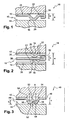
- a seal 10 of the prior art capable of being disposed between a first surface to be sealed 12 and a second surface to be sealed 14, comprising at least one rib 16 arranged near an opening 18.
- the central part of the rib is referenced 20 and the feet 22.
- the gasket 10 comprises a single plate 24 in which is formed a rib 16, the feet 22 of the rib being in contact with the first surface to be sealed 12 and the central portion 20 being in contact with the second surface to be sealed.
- the seal 10 comprises adjacent to the rib, interposed between said rib and the opening, a stopper 26 in the form for example of a fold formed at the edge of the sheet delimiting the opening.
- the seal 10 comprises firstly, at least one so-called active plate 28 and preferably two, each comprising a rib 16 whose central parts are oriented toward each other, and secondly, a spacer plate Disposed between the active plates or in contact with the central part of the rib of the active plate, said intermediate plate supporting a stopper 32, disposed adjacent the rib or ribs, for example disposed edge-to-edge with said intermediate sheet or in the form of a fold formed at the edge delimiting the opening as illustrated by the figure 2 .
- the height h of the stopper 26 or 32 may vary longitudinally.
- the present invention aims to overcome the disadvantages of the prior art by proposing a new seal of simple design, to reduce manufacturing costs, without affecting the sealing capabilities.
- the subject of the invention is a seal capable of being incorporated between two surfaces to be sealed, comprising at least one sheet with at least one rib comprising, in a cross-section on the one hand, a central part capable of being in contact with one of the surfaces to be sealed, directly or indirectly, and secondly, feet arranged on either side of the central part, which may be in contact with the other surface to be sealed, directly or indirectly , characterized in that the central portion of the rib has at least one form providing the crush limiter function.
- these two elements can be made in a single simple operation, which makes it possible to optimize the process for producing such a seal and to reduce manufacturing costs while maintaining an excellent seal. .
- a seal according to the invention capable of being interposed between a first and a second surfaces to be sealed, for example a cylinder head 42 and a motor unit 44 in the case of a cylinder head gasket.
- a seal capable of being interposed between a first and a second surfaces to be sealed, for example a cylinder head 42 and a motor unit 44 in the case of a cylinder head gasket.
- the invention is not limited to this application and covers on the contrary all applications requiring a substantially flat seal.
- gap e may vary in operation.
- the seal 40 comprises at least one sheet or plate, called metal sheet 46, preferably metal, coated or not.
- the seal comprises at least one opening and / or orifice 48 so as to communicate ducts opening respectively at each surface to be sealed.
- the seal comprises at least one opening capable of cooperating with a combustion chamber and orifices allowing the passage of fluids or clamping means such as threaded rods.
- the seal comprises at least one sealing barrier, preferably dynamic, in the form of a rib 50.
- the rib 50 extends continuously or not, circularly or otherwise.
- the rib 50 may surround an opening 48 provided for a combustion chamber as illustrated by the figure 5 .
- the rib may be substantially circular and be disposed at a substantially constant distance from the edge of the seal defining the opening 48.
- the rib 50 comprises firstly, a central portion 52 may be in contact, particularly during assembly, with one of the surfaces to be sealed, directly or indirectly, to the occurrence in direct contact with the motor block 44, and secondly, feet 54 disposed on either side of the central portion 52, capable of being in contact with the other surface to be sealed, directly or indirectly, to the occurrence in contact direct with breech 42.
- Two branches 56 are provided, each capable of connecting the central portion 52 with one of the feet 54.
- the feet 54 each comprise a straight portion connected to the remainder of the plate 46 and a curved portion connecting the right portion to one of the branches 56 of the central portion.
- the seal 40 comprises a crush limiter.
- the rib 50 preferably the central portion 52, comprises a crush limiter.
- the cross section of the central portion 52 has at least one form providing the crush limiter function.
- the central portion 52 comprises at least one corrugation 58.
- the invention is not limited to this form, the crush limiter being capable of having a crenel or triangular or other shape.
- a central part may comprise a combination of all these forms.
- connection between the feet 54 and the central portion 52 of the rib can be elastically deformed so as to press the peak A of said at least one corrugation 58 against the surface to be sealed in contact with the feet 54 of the rib, in particular in operation.
- This arrangement makes it possible to improve the seal, each peak A forming a sealing barrier.
- the one or more ridges A and the feet of the rib are in contact with a first surface to be sealed while at least the connection zones between the legs 56 and the central portion 52 are in contact with the other surface to be sealed.
- the radius of curvature R of the connection zone between the branches 56 and the central portion 52 is greater than the radius of curvature r of the wave or waves 58.
- the radius of curvature curvature R facilitates elastic deformations while the radius of curvature r limits the elastic deformations. This arrangement makes it possible to obtain a good compromise between the resistance to deformation in order to avoid total crushing of the rib and the elasticity of the rib which guarantees the tightness.
- radius of curvature is meant a real curvature as illustrated on the figure 3 , or an imaginary curvature corresponding to the imaginary circle tangent to two successive inclined faces as illustrated on the figure 4 for the radius of curvature R.
- the central portion 52 may comprise several corrugations 58, as illustrated by FIG. figure 4 .
- the distance separating an adjacent hollow and a vertex from the corrugations varies from about 0.4 to 0.8 mm
- the height h varies from about 0.04 to 0.15 mm. depending on the characteristics of the elements to be sealed.
- the crush resistance of the crush limiter or the distribution of the pressure forces can vary along the rib 50 by adjusting the height and / or the number of corrugations.
- the seal 40 may comprise a plate 46, as illustrated in FIGS. FIGS. 6A, 6B, 6D, 6E, 6F and 6G or two plates 46, as illustrated on the Figures 6C, 6H and 6L or more than two plates 46, as illustrated by the Figures 6I, 6J, 6K and 6M .
- the central part may comprise a corrugation, as illustrated on the Figures 6A to 6D , or more, as illustrated in the other figures.
- the corrugations can be centered with respect to the central part or not as illustrated on the Figure 6D .
- the corrugations can all be identical or not as illustrated by the figure 6F .
- the one or more undulations may be oriented in a first direction, as illustrated by the Figure 6A , or towards a second direction, as illustrated by the Figure 6B .
- the radius of curvature of the corrugations can be more or less tight, as illustrated by the Figures 6E and 6G .
- the ribs are oriented towards each other, as illustrated by the FIGS. 6C, 6H, 6I, 6J, 6K, 6L and 6M , or not.
- the ribbed sheets may comprise corrugations at each rib, as illustrated by the FIGS. 6C, 6H, 6I, 6J and 6M or only on one, as illustrated by the Figures 6K and 6L .
- a flat plate can be provided between the ribbed plates as illustrated by the Figures 6J and 6K or plated against one of the ribbed sheets as shown on the figure 6I .
- the profile of the rib incorporating the crush limiter is made in a single operation for example by a stamping operation.
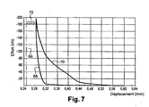
- FIG 7 an example of a compression test of a sheet comprising a rib incorporating a crush limiter according to the invention is shown. This test was carried out with a sheet thickness of the order of 0.25 mm with a crush limiter height h of the order of 0.05 mm.
- seals according to the invention are not limited to the field of head gaskets but can be used in other applications.
Landscapes
- Engineering & Computer Science (AREA)
- General Engineering & Computer Science (AREA)
- Mechanical Engineering (AREA)
- Gasket Seals (AREA)
- Surgical Instruments (AREA)
- Crushing And Pulverization Processes (AREA)
Description
- La présente invention se rapporte à un joint comprenant au moins une nervure incorporant un limiteur d'écrasement, ledit joint étant plus particulièrement destiné à être utilisé en tant que joint de culasse.
- Un joint de culasse, disposé entre un bloc moteur et une culasse, comprend généralement une ou plusieurs feuilles métalliques comportant des ouvertures susceptibles de coopérer avec les chambres de combustion et des orifices permettant le passage de fluides ou des moyens de serrage tels que des tiges filetées.
- L'invention se rapporte plus particulièrement aux joints de culasse dits dynamiques susceptibles de s'adapter d'une part aux variations de l'écartement e entre le bloc moteur et la culasse en raison notamment des phénomènes de déformation-dilatation, et d'autre part, aux variations géométriques telles que l'état de surface, le parallélisme, la planéité ou autres, qui sont susceptibles de varier d'un bloc moteur à l'autre ou d'une culasse à l'autre.
- Ce type de joint comprend généralement une nervure susceptible d'entourer les ouvertures et/ou les orifices de manière à former une barrière d'étanchéité. Pour l'ensemble de la description, on entend par nervure un profil ayant une section transversale avec une partie centrale susceptible d'être en contact avec une première surface à étancher, directement ou indirectement par l'intermédiaire d'un ou plusieurs éléments, et deux pieds, disposés de part et d'autre de la partie centrale, susceptibles d'être en contact avec la seconde surface à étancher, directement ou indirectement par l'intermédiaire d'un ou plusieurs éléments. Généralement, une nervure a un profil en forme d'oméga. En fonction des cas, la partie centrale peut être courbe ou comprendre une portion rectiligne. De même, la nervure peut s'étendre longitudinalement selon une forme circulaire ou non en fonction de la zone à étancher.
- Lorsque le joint est disposé entre le bloc moteur et la culasse, la nervure est légèrement comprimée et se déforme de manière à s'adapter à la géométrie des différents éléments. En raison de son élasticité, la nervure est susceptible de se déformer lors du fonctionnement pour s'adapter aux variations de l'écartement e entre le bloc moteur et la culasse, la partie centrale conservant le contact avec la culasse directement ou indirectement et les pieds conservant le contact avec le bloc moteur directement ou indirectement, ou vice versa la partie centrale étant susceptible d'être en contact avec le bloc moteur ou la culasse indifféremment.
- De manière à conserver l'élasticité de la nervure et ne pas atteindre sa déformation plastique lors du montage ou en fonctionnement, on prévoit généralement de manière adjacente un limiteur d'écrasement, appelé stoppeur lorsque ce dernier est intercalé entre la nervure et une ouverture adaptée à une chambre de combustion.
- Sur les
figures 1 et 2 , on a représenté un joint 10 de l'art antérieur, susceptible d'être disposé entre une première surface à étancher 12 et une seconde surface à étancher 14, comprenant au moins une nervure 16 disposée à proximité d'une ouverture 18. La partie centrale de la nervure est référencée 20 et les pieds 22. - Selon un premier mode de réalisation, illustré par la
figure 1 , le joint 10 comprend une seule tôle 24 dans laquelle est ménagée une nervure 16, les pieds 22 de la nervure étant en contact avec la première surface à étancher 12 et la partie centrale 20 étant en contact avec la seconde surface à étancher 14. Afin de limiter l'écrasement de la nervure 16, le joint 10 comprend de manière adjacente à la nervure, intercalé entre ladite nervure et l'ouverture, un stoppeur 26 sous forme par exemple d'un pli ménagé au niveau du bord de la tôle délimitant l'ouverture. - Selon un autre mode de réalisation, illustré par la
figure 2 , le joint 10 comprend d'une part, au moins une tôle dite active 28 et de préférence deux, chacune comprenant une nervure 16 dont les parties centrales sont orientées l'une vers l'autre, et d'autre part, une tôle intercalaire 30 disposée entre les tôles actives ou en contact avec la partie centrale de la nervure de la tôle active, ladite tôle intercalaire supportant un stoppeur 32, disposé de manière adjacente à la ou aux nervures, par exemple disposé bord à bord avec ladite tôle intercalaire ou sous forme d'un pli ménagé au niveau du bord délimitant l'ouverture comme illustré par lafigure 2 . - Pour obtenir une répartition des efforts de compression sensiblement uniforme, la hauteur h du stoppeur 26 ou 32 peut varier longitudinalement.
- Afin de réduire les coûts de fabrication tout en conservant une excellente étanchéité, on tend à privilégier les solutions comprenant une seule tôle, comme par exemple le joint métallique divulgué dans le document
EP-A-0 834 687 . - Toutefois même dans ce cas, on note que la réalisation du limiteur d'écrasement est généralement problématique et génère des surcoûts.
- Aussi, la présente invention vise à pallier les inconvénients de l'art antérieur en proposant un nouveau joint de conception simple, permettant de réduire les coûts de fabrication, sans affecter les capacités d'étanchéité.
- A cet effet, l'invention a pour objet un joint susceptible d'être incorporé entre deux surfaces à étancher, comprenant au moins une tôle avec au moins une nervure comportant selon une section transversale d'une part, une partie centrale susceptible d'être en contact avec une des surfaces à étancher, directement ou indirectement, et d'autre part, des pieds disposés de part et d'autre de la partie centrale, susceptibles d'être en contact avec l'autre surface à étancher, directement ou indirectement, caractérisé en ce que la partie centrale de la nervure a au moins une forme assurant la fonction de limiteur d'écrasement.
- En incorporant le limiteur d'écrasement à la nervure, on peut réaliser en une seule opération simple ces deux éléments ce qui permet d'optimiser le procédé de réalisation d'un tel joint et de réduire les coûts de fabrication tout en conservant une excellente étanchéité.
- D'autres caractéristiques et avantages ressortiront de la description qui va suivre de l'invention, description donnée à titre d'exemple uniquement, en regard des dessins annexés sur lesquels:
- la
figure 1 est une coupe transversale illustrant un premier mode de réalisation d'un joint selon l'art antérieur, - la
figure 2 est une coupe transversale illustrant un autre mode de réalisation d'un joint selon l'art antérieur, - la
figure 3 est une coupe transversale illustrant un joint selon l'invention intercalé entre deux surfaces à étancher, - la
figure 4 est une coupe transversale illustrant en détail la section de la nervure d'un joint selon l'invention, - la
figure 5 est une vue de dessus d'une partie d'un joint selon l'invention, - les
figures 6A à 6M illustrent différentes variantes de joints selon l'invention, et - la
figure 7 est une courbe illustrant les déformations d'une nervure selon l'invention. - Sur la
figure 3 , on a représenté en 40 un joint selon l'invention, susceptible d'être intercalé entre une première et une seconde surfaces à étancher, par exemple une culasse 42 et un bloc moteur 44 dans le cas d'un joint de culasse. Bien entendu, l'invention n'est pas limitée à cette application et couvre au contraire toutes les applications nécessitant un joint sensiblement plat. - Selon les cas, la distance séparant les deux surfaces à étancher 42 et 44, appelée écartement e peut varier en fonctionnement.
- Le joint 40 comprend au moins une feuille ou plaque, appelée tôle 46, de préférence métallique, revêtue ou non.
- Le joint comprend au moins une ouverture et/ou orifice 48 de manière à faire communiquer des conduits débouchant respectivement au niveau de chaque surface à étancher. Dans le cas d'un joint de culasse, le joint comprend au moins une ouverture susceptible de coopérer avec une chambre de combustion et des orifices permettant le passage de fluides ou des moyens de serrage tels que des tiges filetées.
- De manière connue, le joint comprend au moins une barrière d'étanchéité, de préférence dynamique, sous forme d'une nervure 50.
- Selon les cas, la nervure 50 s'étend de manière continue ou non, de manière circulaire ou non. A titre d'exemple, la nervure 50 peut entourer une ouverture 48 prévue pour une chambre de combustion comme illustré par la
figure 5 . Dans ce cas, la nervure peut être sensiblement circulaire et être disposée à une distance sensiblement constante du bord du joint délimitant l'ouverture 48. - Selon une section transversale, la nervure 50 comprend d'une part, une partie centrale 52 susceptible d'être en contact, notamment lors du montage, avec une des surfaces à étancher, directement ou indirectement, à l'occurrence en contact direct avec le bloc moteur 44, et d'autre part, des pieds 54 disposés de part et d'autre de la partie centrale 52, susceptibles d'être en contact avec l'autre surface à étancher, directement ou indirectement, à l'occurrence en contact direct avec la culasse 42.
- Deux branches 56, plus ou moins inclinées, sont prévues, susceptibles de relier chacune la partie centrale 52 avec l'un des pieds 54. En complément, les pieds 54 comprennent chacun une portion droite reliée au reste de la tôle 46 et une portion courbe reliant la portion droite à une des branches 56 de la partie centrale.
- De manière à conserver l'élasticité de la nervure 50 et limiter son écrasement lors du montage ou en fonctionnement, le joint 40 comprend un limiteur d'écrasement.
- Selon l'invention, la nervure 50, de préférence la partie centrale 52, comprend un limiteur d'écrasement. Selon l'invention, la section transversale de la partie centrale 52 a au moins une forme assurant la fonction de limiteur d'écrasement. A cet effet, comme illustré sur la
figure 3 , la partie centrale 52 comprend au moins une ondulation 58. L'invention n'est pas limitée à cette forme, le limiteur d'écrasement étant susceptible d'avoir une forme en créneau ou triangulaire ou autre. Une partie centrale peut comprendre une combinaison de toutes ces formes. - Selon une autre caractéristique de l'invention, la liaison entre les pieds 54 et la partie centrale 52 de la nervure peut se déformer de manière élastique afin de plaquer la crête A de ladite au moins une ondulation 58 contre la surface à étancher en contact avec les pieds 54 de la nervure, notamment en fonctionnement. Cet agencement permet d'améliorer l'étanchéité, chaque crête A formant une barrière d'étanchéité. Ainsi, en fonctionnement, la ou les crêtes A ainsi que les pieds de la nervure sont en contact avec une première surface à étancher alors qu'au moins les zones de liaison entre les branches 56 et la partie centrale 52 sont en contact avec l'autre surface à étancher.
- Selon une autre caractéristique de l'invention, le rayon de courbure R de la zone de liaison entre les branches 56 et la partie centrale 52 est supérieur au rayon de courbure r de la ou des ondulations 58. Ainsi, le rayon de courbure R facilite les déformations élastiques alors que le rayon de courbure r limite les déformations élastiques. Cet agencement permet d'obtenir un bon compromis entre la résistance à la déformation afin d'éviter l'écrasement total de la nervure et l'élasticité de la nervure qui garantit l'étanchéité.
- Par rayon de courbure, on entend une courbure réelle telle qu'illustrée sur la
figure 3 , ou une courbure imaginaire correspondant au cercle imaginaire tangent à deux pans successifs inclinés comme illustré sur lafigure 4 pour le rayon de courbure R. - Selon une autre variante, la partie centrale 52 peut comprendre plusieurs ondulations 58, comme illustré par la
figure 4 . - A titre d'exemple, la distance séparant un creux et un sommet adjacents des ondulations varie de l'ordre de 0,4 à 0,8 mm, la hauteur h varie de l'ordre de 0,04 à 0,15 mm en fonction des caractéristiques des éléments à étancher.
- Selon une autre caractéristique de l'invention, la résistance à l'écrasement du limiteur d'écrasement ou la répartition des efforts de pression peut varier le long de la nervure 50 en ajustant la hauteur et/ou le nombre des ondulations.
- On peut aussi fractionner le limiteur d'écrasement.
- Selon les variantes, le joint 40 peut comprendre une tôle 46, comme illustré sur les
figures 6A, 6B, 6D, 6E, 6F et 6G ou deux tôles 46, comme illustré sur lesfigures 6C, 6H et 6L ou plus de deux tôles 46, comme illustré par lesfigures 6I, 6J, 6K et 6M . - Selon les cas, la partie centrale peut comprendre une ondulation, comme illustré sur les
figures 6A à 6D , ou plusieurs, comme illustré sur les autres figures. - Les ondulations peuvent être centrées par rapport à la partie centrale ou non comme illustré sur la
figure 6D . - Les ondulations peuvent être toutes identiques ou non comme illustré par la
figure 6F . - La ou les ondulations peuvent être orientées vers une première direction, comme illustré par la
figure 6A , ou vers une seconde direction, comme illustré par lafigure 6B . - En fonction des cas, le rayon de courbure des ondulations peut être plus ou moins serré, comme illustré par les
figures 6E et 6G . - Pour les variantes incorporant au moins deux tôles les nervures sont orientées l'une vers l'autre, comme illustré par les
figures 6C, 6H, 6I, 6J, 6K, 6L et 6M , ou non. - Les tôles nervurées peuvent comprendre des ondulations au niveau de chaque nervure, comme illustré par les
figures 6C, 6H, 6I, 6J et 6M ou seulement sur une, comme illustré par lesfigures 6K et 6L . - De plus, une tôle plate peut être prévue entre les tôles nervurées comme illustré par les
figures 6J et 6K ou plaquée contre l'une des tôles nervurées comme illustré sur lafigure 6I . - Bien entendu, tous les agencements ne sont pas représentés et peuvent varier à l'infini.
- Selon un mode de réalisation préféré, le profil de la nervure incorporant le limiteur d'écrasement est réalisé en une seule opération grâce par exemple à une opération de matriçage.
- Sur la
figure 7 , on a représenté à titre d'exemple un essai de compression d'une tôle comprenant une nervure incorporant un limiteur d'écrasement selon l'invention. Cet essai a été réalisé avec une tôle d'épaisseur de l'ordre de 0,25 mm avec un limiteur d'écrasement de hauteur h de l'ordre de 0,05 mm. - Cet essai de compression a été réalisé sous une charge de 200 KN, courbe 66 c'est-à-dire une valeur supérieure à celle qui peut être générée par le serrage normal de la culasse sur le bloc moteur.
- On note que la courbe 68 correspondant à la décharge se situe au-dessus de la valeur de l'épaisseur de la tôle représentée en 70 et qu'ainsi, la fonction butée est bien assurée par la présente invention. Cette valeur de butée est symbolisée graphiquement en 72.
- Bien entendu, l'invention n'est évidemment pas limitée au mode de réalisation représenté et décrit ci-dessus, mais en couvre au contraire toutes les variantes, notamment en ce qui concerne les dimensions et les formes des différents éléments.
- Enfin, les joints selon l'invention ne sont pas limités au domaine des joints de culasse mais peuvent être utilisés dans d'autres applications.
Claims (7)
- Joint susceptible d'être incorporé entre deux surfaces à étancher (42, 44), comprenant au moins une tôle (46) avec au moins une nervure d'étanchéité (50) comportant selon une section transversale d'une part, une partie centrale (52) susceptible d'être en contact avec une des surfaces à étancher, directement ou indirectement, et d'autre part, des pieds (54) disposés de part et d'autre de la partie centrale (52), susceptibles d'être en contact avec l'autre surface à étancher, directement ou indirectement, caractérisé en ce que la partie centrale de la nervure d'étanchéité (50) a au moins une forme assurant la fonction de limiteur décroisement (58).
- Joint selon la revendication 1, caractérisé en ce que la liaison entre les pieds (54) et la partie centrale (52) de la nervure d'étanchéité peut se déformer de manière élastique afin de plaquer ledit limiteur d'écrasement (58) contre la surface à étancher en contact avec les pieds (54) de la nervure d'étanchéité en fonctionnement.
- Joint selon la revendication 1 ou 2, caractérisé en ce que la partie centrale de la nervure d'étanchéité (50) comprend au moins une ondulation (58), au moins un créneau et/ou au moins une forme en triangle
- Joint selon la revendication 3, caractérisé en ce que la zone de liaison entre les branches (56) et la partie centrale (52) forme un rayon de courbure R supérieur au rayon de courbure r de la ou des ondulations (58).
- Joint selon l'une quelconque des revendications 1 à 4, caractérisé en ce que la hauteur h du limiteur d'écrasement (58) est de l'ordre de 0,04 à 0,15 mm.
- Joint selon l'une quelconque des revendications 3 à 5, caractérisé en ce que la hauteur et/ou le nombre d'ondulations peut varier le long de la nervure d'étanchéité.
- Joint selon l'une quelconque des revendications précédentes, caractérisé en ce que le limiteur d'écrasement est fractionné.
Applications Claiming Priority (1)
| Application Number | Priority Date | Filing Date | Title |
|---|---|---|---|
| FR0452104A FR2875570B1 (fr) | 2004-09-21 | 2004-09-21 | Joint comprenant au moins une nervure incorporant un limiteur d'ecrasement |
Publications (3)
| Publication Number | Publication Date |
|---|---|
| EP1637780A1 EP1637780A1 (fr) | 2006-03-22 |
| EP1637780B1 true EP1637780B1 (fr) | 2008-09-03 |
| EP1637780B9 EP1637780B9 (fr) | 2012-03-21 |
Family
ID=34948670
Family Applications (1)
| Application Number | Title | Priority Date | Filing Date |
|---|---|---|---|
| EP05015831A Revoked EP1637780B9 (fr) | 2004-09-21 | 2005-07-21 | Joint comprenant au moins une nervure incorporant un limiteur d'écrasement |
Country Status (8)
| Country | Link |
|---|---|
| US (1) | US20060061045A1 (fr) |
| EP (1) | EP1637780B9 (fr) |
| JP (1) | JP2006090549A (fr) |
| AT (1) | ATE407310T1 (fr) |
| CA (1) | CA2514063A1 (fr) |
| DE (1) | DE602005009455D1 (fr) |
| FR (1) | FR2875570B1 (fr) |
| MX (1) | MXPA05009945A (fr) |
Cited By (1)
| Publication number | Priority date | Publication date | Assignee | Title |
|---|---|---|---|---|
| CN102388244A (zh) * | 2009-06-25 | 2012-03-21 | 联邦摩高密封系统公司 | 具有实心压条的平垫片 |
Families Citing this family (19)
| Publication number | Priority date | Publication date | Assignee | Title |
|---|---|---|---|---|
| DE102005003017B4 (de) * | 2004-01-23 | 2019-10-24 | Koichi Hatamura | Metalldichtung |
| DE102004031491B4 (de) * | 2004-06-30 | 2013-01-03 | Federal-Mogul Sealing Systems Gmbh | Flachdichtung |
| JP2007139177A (ja) * | 2005-10-20 | 2007-06-07 | Japan Metal Gasket Co Ltd | ガスケット |
| EP1985896B1 (fr) * | 2007-04-24 | 2012-12-12 | REINZ-Dichtungs-GmbH | Joint plat métallique |
| US8371587B2 (en) * | 2008-01-31 | 2013-02-12 | GM Global Technology Operations LLC | Metal bead seal for fuel cell plate |
| EP2088305B1 (fr) * | 2008-02-06 | 2018-09-05 | REINZ-Dichtungs-GmbH | Joint plat métallique |
| US8632077B2 (en) * | 2008-02-13 | 2014-01-21 | Federal-Mogul Corporation | Multilayer static gasket with bead compression limiter |
| JP4794643B2 (ja) * | 2009-03-03 | 2011-10-19 | 石川ガスケット株式会社 | 金属積層形ガスケット |
| US8128098B2 (en) * | 2009-10-22 | 2012-03-06 | Dana Automotive Systems Group, Llc | Multi-layered gasket |
| US20120187638A1 (en) * | 2011-01-20 | 2012-07-26 | Freudenberg-Nok General Partnership | Cast Gasket |
| JP5699039B2 (ja) * | 2011-05-26 | 2015-04-08 | 日本リークレス工業株式会社 | 金属ガスケット |
| US8752841B2 (en) | 2012-05-18 | 2014-06-17 | Federal-Mogul Corporation | Gasket with a compression limiter |
| US20150069718A1 (en) * | 2013-09-12 | 2015-03-12 | Federal-Mogul Corporation | Metal gasket assembly |
| JP6028150B2 (ja) * | 2014-03-07 | 2016-11-16 | 日本リークレス工業株式会社 | 金属ガスケット |
| US10359003B2 (en) | 2014-06-23 | 2019-07-23 | Tenneco Inc. | Cylinder head gasket with compression limiter and full bead loading |
| DE202016104243U1 (de) * | 2016-08-02 | 2017-11-03 | Reinz-Dichtungs-Gmbh | Flachdichtung sowie Verbrennungsmotor mit einer derartigen Flachdichtung |
| JP7038072B2 (ja) * | 2019-02-22 | 2022-03-17 | 本田技研工業株式会社 | 燃料電池用接合セパレータ及び燃料電池 |
| JP7103994B2 (ja) * | 2019-05-21 | 2022-07-20 | 本田技研工業株式会社 | 燃料電池用セパレータ部材及び燃料電池スタック |
| US11668395B2 (en) | 2019-10-30 | 2023-06-06 | Federal-Mogul Motorparts Llc | Gasket including channel-retention features |
Family Cites Families (15)
| Publication number | Priority date | Publication date | Assignee | Title |
|---|---|---|---|---|
| GB1583322A (en) * | 1978-02-02 | 1981-01-28 | Nicholson T P | Corrugated gaskets |
| US4451051A (en) * | 1982-05-18 | 1984-05-29 | Nicholson Terence P | Cylinder head gaskets |
| JPH07110392B2 (ja) * | 1988-03-28 | 1995-11-29 | 日本ガスケット株式会社 | 金属ガスケットの製造方法 |
| US4995624A (en) * | 1988-09-12 | 1991-02-26 | Ishikawa Gasket Co., Ltd. | Steel laminate gasket with wide sealing area |
| JP2521155Y2 (ja) * | 1990-08-07 | 1996-12-25 | 石川ガスケット 株式会社 | 断熱性金属積層形ガスケット |
| US5570892A (en) * | 1995-06-27 | 1996-11-05 | Ishikawa Gasket Co., Ltd. | Metal gasket with a bead having pressure adjusting portion |
| DE69634031D1 (de) * | 1995-11-07 | 2005-01-20 | Nicholsons Aircraft Seals Ltd | Abdichtung |
| JP3003026B2 (ja) * | 1996-10-07 | 2000-01-24 | 石川ガスケット株式会社 | 金属板ガスケット |
| US5711537A (en) * | 1996-12-13 | 1998-01-27 | Ishikawa Gasket Co., Ltd. | Metal gasket with a bead surrounding bolt and oil holes |
| JP2964333B1 (ja) * | 1998-05-29 | 1999-10-18 | 石川ガスケット株式会社 | 金属板ガスケット |
| DE19928580B4 (de) * | 1999-06-22 | 2005-08-25 | Reinz Dichtungs-Gmbh | Flachdichtung und Verfahren zum Herstellen einer Flachdichtung |
| CA2411276C (fr) * | 2000-06-15 | 2009-08-18 | Reinz-Dichtungs-Gmbh & Co. Kg | Joint plat et son procede de production |
| DE10310014B4 (de) * | 2003-02-28 | 2009-09-10 | Reinz-Dichtungs-Gmbh | Zylinderkopf-Flachdichtung |
| US7234705B2 (en) * | 2003-08-28 | 2007-06-26 | Freudenberg-Nok General Partnership | Sealing gasket with flexible stopper |
| FR2864914B1 (fr) * | 2004-01-13 | 2007-02-23 | Meillor Sa | Procede d'obtention d'une surepaisseur sur une tole, tole ainsi obtenue et joint incorporant ladite tole |
-
2004
- 2004-09-21 FR FR0452104A patent/FR2875570B1/fr not_active Expired - Fee Related
-
2005
- 2005-07-21 DE DE602005009455T patent/DE602005009455D1/de active Active
- 2005-07-21 EP EP05015831A patent/EP1637780B9/fr not_active Revoked
- 2005-07-21 AT AT05015831T patent/ATE407310T1/de not_active IP Right Cessation
- 2005-07-26 CA CA002514063A patent/CA2514063A1/fr not_active Abandoned
- 2005-09-01 US US11/218,051 patent/US20060061045A1/en not_active Abandoned
- 2005-09-19 MX MXPA05009945A patent/MXPA05009945A/es not_active Application Discontinuation
- 2005-09-21 JP JP2005274793A patent/JP2006090549A/ja active Pending
Cited By (2)
| Publication number | Priority date | Publication date | Assignee | Title |
|---|---|---|---|---|
| CN102388244A (zh) * | 2009-06-25 | 2012-03-21 | 联邦摩高密封系统公司 | 具有实心压条的平垫片 |
| CN102388244B (zh) * | 2009-06-25 | 2015-03-11 | 联邦摩高密封系统公司 | 具有实心压条的平垫片 |
Also Published As
| Publication number | Publication date |
|---|---|
| DE602005009455D1 (de) | 2008-10-16 |
| MXPA05009945A (es) | 2006-03-27 |
| CA2514063A1 (fr) | 2006-03-21 |
| FR2875570B1 (fr) | 2007-02-16 |
| FR2875570A1 (fr) | 2006-03-24 |
| JP2006090549A (ja) | 2006-04-06 |
| ATE407310T1 (de) | 2008-09-15 |
| US20060061045A1 (en) | 2006-03-23 |
| EP1637780B9 (fr) | 2012-03-21 |
| EP1637780A1 (fr) | 2006-03-22 |
Similar Documents
| Publication | Publication Date | Title |
|---|---|---|
| EP1637780B1 (fr) | Joint comprenant au moins une nervure incorporant un limiteur d'écrasement | |
| EP2895773B1 (fr) | Joint d'étanchéité, en particulier pour liquide sous pression | |
| FR2987881A1 (fr) | Dispositif de raccordement securise, notamment pour canalisation, embout pour ce dispositif et procede de fabrication d'un ecrou associe. | |
| EP1693606B1 (fr) | Joint métallique comportant une surépaisseur formée de protubérances discontinues | |
| EP2683966B1 (fr) | Joint semi-ondulé | |
| EP1521019B1 (fr) | Joint multicouche comprenant au moins une cale de surépaisseur | |
| EP1409898B1 (fr) | Joint de culasse comprenant un stoppeur bord a bord | |
| EP2381143A1 (fr) | Joint d'étanchéité, reservoir comprenant un tel joint et utilisation d'un tel joint | |
| EP2299089A1 (fr) | Dispositif d'étanchéité d'un orifice sensiblement cylindrique | |
| EP1430241B1 (fr) | Joint de culasse comprenant un stoppeur bord a bord lie par agrafage | |
| EP1619426B9 (fr) | Joint d'étanchéité comprenant une âme flexible et au moins une barrière d'étanchéité en matériau souple | |
| EP1536166B1 (fr) | Joint comprenant une tôle avec une surépaisseur | |
| EP2202431B1 (fr) | Joint de bloc moteur, notamment pour le montage d'un composant faiblement rigide sur ledit bloc moteur | |
| EP2354604B1 (fr) | Joint métallique comportant une surépaisseur formée par au moins une nervure en lacets | |
| EP2202432A1 (fr) | Joint d'etanchéité | |
| EP1409897B1 (fr) | Joint de culasse comprenant un stoppeur bord a bord | |
| FR2863010A1 (fr) | Stoppeur adaptable et joint de culasse equipe dudit stoppeur | |
| EP1555466B1 (fr) | Procédé d'obtention d'une surépaisseur sur une tôle et joint d'étanchéité incorporant ladite tôle | |
| FR2827637A1 (fr) | Joint de culasse comprenant un stoppeur bord a bord | |
| FR2827639A1 (fr) | Joint de culasse comprenant un stoppeur bord a bord |
Legal Events
| Date | Code | Title | Description |
|---|---|---|---|
| PUAI | Public reference made under article 153(3) epc to a published international application that has entered the european phase |
Free format text: ORIGINAL CODE: 0009012 |
|
| AK | Designated contracting states |
Kind code of ref document: A1 Designated state(s): AT BE BG CH CY CZ DE DK EE ES FI FR GB GR HU IE IS IT LI LT LU LV MC NL PL PT RO SE SI SK TR |
|
| AX | Request for extension of the european patent |
Extension state: AL BA HR MK YU |
|
| 17P | Request for examination filed |
Effective date: 20060526 |
|
| AKX | Designation fees paid |
Designated state(s): AT BE BG CH CY CZ DE DK EE ES FI FR GB GR HU IE IS IT LI LT LU LV MC NL PL PT RO SE SI SK TR |
|
| GRAP | Despatch of communication of intention to grant a patent |
Free format text: ORIGINAL CODE: EPIDOSNIGR1 |
|
| GRAS | Grant fee paid |
Free format text: ORIGINAL CODE: EPIDOSNIGR3 |
|
| GRAA | (expected) grant |
Free format text: ORIGINAL CODE: 0009210 |
|
| AK | Designated contracting states |
Kind code of ref document: B1 Designated state(s): AT BE BG CH CY CZ DE DK EE ES FI FR GB GR HU IE IS IT LI LT LU LV MC NL PL PT RO SE SI SK TR |
|
| REG | Reference to a national code |
Ref country code: GB Ref legal event code: FG4D Free format text: NOT ENGLISH |
|
| REG | Reference to a national code |
Ref country code: CH Ref legal event code: EP |
|
| REG | Reference to a national code |
Ref country code: IE Ref legal event code: FG4D Free format text: LANGUAGE OF EP DOCUMENT: FRENCH |
|
| REF | Corresponds to: |
Ref document number: 602005009455 Country of ref document: DE Date of ref document: 20081016 Kind code of ref document: P |
|
| PG25 | Lapsed in a contracting state [announced via postgrant information from national office to epo] |
Ref country code: ES Free format text: LAPSE BECAUSE OF FAILURE TO SUBMIT A TRANSLATION OF THE DESCRIPTION OR TO PAY THE FEE WITHIN THE PRESCRIBED TIME-LIMIT Effective date: 20081214 Ref country code: LT Free format text: LAPSE BECAUSE OF FAILURE TO SUBMIT A TRANSLATION OF THE DESCRIPTION OR TO PAY THE FEE WITHIN THE PRESCRIBED TIME-LIMIT Effective date: 20080903 Ref country code: NL Free format text: LAPSE BECAUSE OF FAILURE TO SUBMIT A TRANSLATION OF THE DESCRIPTION OR TO PAY THE FEE WITHIN THE PRESCRIBED TIME-LIMIT Effective date: 20080903 |
|
| PG25 | Lapsed in a contracting state [announced via postgrant information from national office to epo] |
Ref country code: FI Free format text: LAPSE BECAUSE OF FAILURE TO SUBMIT A TRANSLATION OF THE DESCRIPTION OR TO PAY THE FEE WITHIN THE PRESCRIBED TIME-LIMIT Effective date: 20080903 Ref country code: SI Free format text: LAPSE BECAUSE OF FAILURE TO SUBMIT A TRANSLATION OF THE DESCRIPTION OR TO PAY THE FEE WITHIN THE PRESCRIBED TIME-LIMIT Effective date: 20080903 Ref country code: AT Free format text: LAPSE BECAUSE OF FAILURE TO SUBMIT A TRANSLATION OF THE DESCRIPTION OR TO PAY THE FEE WITHIN THE PRESCRIBED TIME-LIMIT Effective date: 20080903 Ref country code: LV Free format text: LAPSE BECAUSE OF FAILURE TO SUBMIT A TRANSLATION OF THE DESCRIPTION OR TO PAY THE FEE WITHIN THE PRESCRIBED TIME-LIMIT Effective date: 20080903 |
|
| NLV1 | Nl: lapsed or annulled due to failure to fulfill the requirements of art. 29p and 29m of the patents act | ||
| REG | Reference to a national code |
Ref country code: IE Ref legal event code: FD4D |
|
| PG25 | Lapsed in a contracting state [announced via postgrant information from national office to epo] |
Ref country code: IE Free format text: LAPSE BECAUSE OF FAILURE TO SUBMIT A TRANSLATION OF THE DESCRIPTION OR TO PAY THE FEE WITHIN THE PRESCRIBED TIME-LIMIT Effective date: 20080903 Ref country code: BG Free format text: LAPSE BECAUSE OF FAILURE TO SUBMIT A TRANSLATION OF THE DESCRIPTION OR TO PAY THE FEE WITHIN THE PRESCRIBED TIME-LIMIT Effective date: 20081203 |
|
| PG25 | Lapsed in a contracting state [announced via postgrant information from national office to epo] |
Ref country code: CZ Free format text: LAPSE BECAUSE OF FAILURE TO SUBMIT A TRANSLATION OF THE DESCRIPTION OR TO PAY THE FEE WITHIN THE PRESCRIBED TIME-LIMIT Effective date: 20080903 Ref country code: RO Free format text: LAPSE BECAUSE OF FAILURE TO SUBMIT A TRANSLATION OF THE DESCRIPTION OR TO PAY THE FEE WITHIN THE PRESCRIBED TIME-LIMIT Effective date: 20080903 Ref country code: SK Free format text: LAPSE BECAUSE OF FAILURE TO SUBMIT A TRANSLATION OF THE DESCRIPTION OR TO PAY THE FEE WITHIN THE PRESCRIBED TIME-LIMIT Effective date: 20080903 Ref country code: PT Free format text: LAPSE BECAUSE OF FAILURE TO SUBMIT A TRANSLATION OF THE DESCRIPTION OR TO PAY THE FEE WITHIN THE PRESCRIBED TIME-LIMIT Effective date: 20090203 Ref country code: IS Free format text: LAPSE BECAUSE OF FAILURE TO SUBMIT A TRANSLATION OF THE DESCRIPTION OR TO PAY THE FEE WITHIN THE PRESCRIBED TIME-LIMIT Effective date: 20090103 |
|
| PLBI | Opposition filed |
Free format text: ORIGINAL CODE: 0009260 |
|
| PLAX | Notice of opposition and request to file observation + time limit sent |
Free format text: ORIGINAL CODE: EPIDOSNOBS2 |
|
| 26 | Opposition filed |
Opponent name: REINZ-DICHTUNGS-GMBH Effective date: 20090526 |
|
| PG25 | Lapsed in a contracting state [announced via postgrant information from national office to epo] |
Ref country code: DK Free format text: LAPSE BECAUSE OF FAILURE TO SUBMIT A TRANSLATION OF THE DESCRIPTION OR TO PAY THE FEE WITHIN THE PRESCRIBED TIME-LIMIT Effective date: 20080903 Ref country code: EE Free format text: LAPSE BECAUSE OF FAILURE TO SUBMIT A TRANSLATION OF THE DESCRIPTION OR TO PAY THE FEE WITHIN THE PRESCRIBED TIME-LIMIT Effective date: 20080903 |
|
| PG25 | Lapsed in a contracting state [announced via postgrant information from national office to epo] |
Ref country code: IT Free format text: LAPSE BECAUSE OF FAILURE TO SUBMIT A TRANSLATION OF THE DESCRIPTION OR TO PAY THE FEE WITHIN THE PRESCRIBED TIME-LIMIT Effective date: 20080903 |
|
| PLBB | Reply of patent proprietor to notice(s) of opposition received |
Free format text: ORIGINAL CODE: EPIDOSNOBS3 |
|
| PG25 | Lapsed in a contracting state [announced via postgrant information from national office to epo] |
Ref country code: SE Free format text: LAPSE BECAUSE OF FAILURE TO SUBMIT A TRANSLATION OF THE DESCRIPTION OR TO PAY THE FEE WITHIN THE PRESCRIBED TIME-LIMIT Effective date: 20081203 |
|
| BERE | Be: lapsed |
Owner name: CARL FREUDENBERG K.G. Effective date: 20090731 |
|
| PG25 | Lapsed in a contracting state [announced via postgrant information from national office to epo] |
Ref country code: MC Free format text: LAPSE BECAUSE OF NON-PAYMENT OF DUE FEES Effective date: 20090731 |
|
| REG | Reference to a national code |
Ref country code: CH Ref legal event code: PL |
|
| GBPC | Gb: european patent ceased through non-payment of renewal fee |
Effective date: 20090721 |
|
| PG25 | Lapsed in a contracting state [announced via postgrant information from national office to epo] |
Ref country code: LI Free format text: LAPSE BECAUSE OF NON-PAYMENT OF DUE FEES Effective date: 20090731 Ref country code: CH Free format text: LAPSE BECAUSE OF NON-PAYMENT OF DUE FEES Effective date: 20090731 |
|
| PG25 | Lapsed in a contracting state [announced via postgrant information from national office to epo] |
Ref country code: GB Free format text: LAPSE BECAUSE OF NON-PAYMENT OF DUE FEES Effective date: 20090721 Ref country code: PL Free format text: LAPSE BECAUSE OF FAILURE TO SUBMIT A TRANSLATION OF THE DESCRIPTION OR TO PAY THE FEE WITHIN THE PRESCRIBED TIME-LIMIT Effective date: 20080903 |
|
| PG25 | Lapsed in a contracting state [announced via postgrant information from national office to epo] |
Ref country code: BE Free format text: LAPSE BECAUSE OF NON-PAYMENT OF DUE FEES Effective date: 20090731 |
|
| PG25 | Lapsed in a contracting state [announced via postgrant information from national office to epo] |
Ref country code: GR Free format text: LAPSE BECAUSE OF FAILURE TO SUBMIT A TRANSLATION OF THE DESCRIPTION OR TO PAY THE FEE WITHIN THE PRESCRIBED TIME-LIMIT Effective date: 20081204 |
|
| PG25 | Lapsed in a contracting state [announced via postgrant information from national office to epo] |
Ref country code: LU Free format text: LAPSE BECAUSE OF NON-PAYMENT OF DUE FEES Effective date: 20090721 |
|
| PG25 | Lapsed in a contracting state [announced via postgrant information from national office to epo] |
Ref country code: HU Free format text: LAPSE BECAUSE OF FAILURE TO SUBMIT A TRANSLATION OF THE DESCRIPTION OR TO PAY THE FEE WITHIN THE PRESCRIBED TIME-LIMIT Effective date: 20090304 |
|
| PG25 | Lapsed in a contracting state [announced via postgrant information from national office to epo] |
Ref country code: TR Free format text: LAPSE BECAUSE OF FAILURE TO SUBMIT A TRANSLATION OF THE DESCRIPTION OR TO PAY THE FEE WITHIN THE PRESCRIBED TIME-LIMIT Effective date: 20080903 |
|
| PG25 | Lapsed in a contracting state [announced via postgrant information from national office to epo] |
Ref country code: CY Free format text: LAPSE BECAUSE OF FAILURE TO SUBMIT A TRANSLATION OF THE DESCRIPTION OR TO PAY THE FEE WITHIN THE PRESCRIBED TIME-LIMIT Effective date: 20080903 |
|
| RAP2 | Party data changed (patent owner data changed or rights of a patent transferred) |
Owner name: ELRINGKLINGER AG |
|
| PLAY | Examination report in opposition despatched + time limit |
Free format text: ORIGINAL CODE: EPIDOSNORE2 |
|
| PLBC | Reply to examination report in opposition received |
Free format text: ORIGINAL CODE: EPIDOSNORE3 |
|
| PLAH | Information related to despatch of examination report in opposition + time limit modified |
Free format text: ORIGINAL CODE: EPIDOSCORE2 |
|
| PLAY | Examination report in opposition despatched + time limit |
Free format text: ORIGINAL CODE: EPIDOSNORE2 |
|
| PLAH | Information related to despatch of examination report in opposition + time limit modified |
Free format text: ORIGINAL CODE: EPIDOSCORE2 |
|
| PLBC | Reply to examination report in opposition received |
Free format text: ORIGINAL CODE: EPIDOSNORE3 |
|
| PGFP | Annual fee paid to national office [announced via postgrant information from national office to epo] |
Ref country code: DE Payment date: 20140724 Year of fee payment: 10 |
|
| PGFP | Annual fee paid to national office [announced via postgrant information from national office to epo] |
Ref country code: FR Payment date: 20140724 Year of fee payment: 10 |
|
| PLAB | Opposition data, opponent's data or that of the opponent's representative modified |
Free format text: ORIGINAL CODE: 0009299OPPO |
|
| R26 | Opposition filed (corrected) |
Opponent name: REINZ-DICHTUNGS-GMBH Effective date: 20090526 |
|
| RDAF | Communication despatched that patent is revoked |
Free format text: ORIGINAL CODE: EPIDOSNREV1 |
|
| REG | Reference to a national code |
Ref country code: DE Ref legal event code: R064 Ref document number: 602005009455 Country of ref document: DE Ref country code: DE Ref legal event code: R103 Ref document number: 602005009455 Country of ref document: DE |
|
| REG | Reference to a national code |
Ref country code: DE Ref legal event code: R119 Ref document number: 602005009455 Country of ref document: DE |
|
| RDAG | Patent revoked |
Free format text: ORIGINAL CODE: 0009271 |
|
| STAA | Information on the status of an ep patent application or granted ep patent |
Free format text: STATUS: PATENT REVOKED |
|
| REG | Reference to a national code |
Ref country code: FR Ref legal event code: ST Effective date: 20160331 |
|
| 27W | Patent revoked |
Effective date: 20160101 |
|
| PG25 | Lapsed in a contracting state [announced via postgrant information from national office to epo] |
Ref country code: FR Free format text: LAPSE BECAUSE OF NON-PAYMENT OF DUE FEES Effective date: 20150731 |