EP1637511A2 - Actionneur pyrotechnique muni d'une charge comprenant un oxydant et un réducteur dissociés - Google Patents
Actionneur pyrotechnique muni d'une charge comprenant un oxydant et un réducteur dissociés Download PDFInfo
- Publication number
- EP1637511A2 EP1637511A2 EP05291744A EP05291744A EP1637511A2 EP 1637511 A2 EP1637511 A2 EP 1637511A2 EP 05291744 A EP05291744 A EP 05291744A EP 05291744 A EP05291744 A EP 05291744A EP 1637511 A2 EP1637511 A2 EP 1637511A2
- Authority
- EP
- European Patent Office
- Prior art keywords
- actuator
- reducing material
- oxidant
- pyrotechnic
- gases
- Prior art date
- Legal status (The legal status is an assumption and is not a legal conclusion. Google has not performed a legal analysis and makes no representation as to the accuracy of the status listed.)
- Granted
Links
- 239000007800 oxidant agent Substances 0.000 title claims abstract description 21
- 239000003638 chemical reducing agent Substances 0.000 title description 2
- 239000007789 gas Substances 0.000 claims abstract description 33
- 230000001590 oxidative effect Effects 0.000 claims abstract description 33
- 239000000463 material Substances 0.000 claims abstract description 30
- 239000001301 oxygen Substances 0.000 claims abstract description 22
- 229910052760 oxygen Inorganic materials 0.000 claims abstract description 22
- QVGXLLKOCUKJST-UHFFFAOYSA-N atomic oxygen Chemical compound [O] QVGXLLKOCUKJST-UHFFFAOYSA-N 0.000 claims abstract description 19
- 239000012530 fluid Substances 0.000 claims abstract description 15
- 230000001105 regulatory effect Effects 0.000 claims abstract description 6
- NILJXUMQIIUAFY-UHFFFAOYSA-N hydroxylamine;nitric acid Chemical compound ON.O[N+]([O-])=O NILJXUMQIIUAFY-UHFFFAOYSA-N 0.000 claims abstract description 3
- 239000002184 metal Substances 0.000 claims abstract description 3
- 229910052751 metal Inorganic materials 0.000 claims abstract description 3
- 239000000025 natural resin Substances 0.000 claims abstract description 3
- -1 oxygen peroxide Chemical class 0.000 claims abstract description 3
- 239000001993 wax Substances 0.000 claims abstract description 3
- 238000000197 pyrolysis Methods 0.000 claims description 16
- 238000006243 chemical reaction Methods 0.000 claims description 13
- 239000000110 cooling liquid Substances 0.000 claims description 8
- 239000003999 initiator Substances 0.000 claims description 8
- 239000002826 coolant Substances 0.000 claims description 7
- 239000007788 liquid Substances 0.000 claims description 6
- 230000000694 effects Effects 0.000 claims description 5
- 229920003229 poly(methyl methacrylate) Polymers 0.000 claims description 4
- 239000004926 polymethyl methacrylate Substances 0.000 claims description 4
- 239000007787 solid Substances 0.000 claims description 3
- 229920004939 Cariflex™ Polymers 0.000 claims description 2
- 239000008246 gaseous mixture Substances 0.000 claims description 2
- 150000002739 metals Chemical class 0.000 claims description 2
- 239000000203 mixture Substances 0.000 abstract description 2
- 229920000642 polymer Polymers 0.000 abstract 1
- 239000002952 polymeric resin Substances 0.000 abstract 1
- 239000000057 synthetic resin Substances 0.000 abstract 1
- 238000002485 combustion reaction Methods 0.000 description 6
- LFQSCWFLJHTTHZ-UHFFFAOYSA-N Ethanol Chemical compound CCO LFQSCWFLJHTTHZ-UHFFFAOYSA-N 0.000 description 4
- 238000001816 cooling Methods 0.000 description 2
- 238000011144 upstream manufacturing Methods 0.000 description 2
- 238000010521 absorption reaction Methods 0.000 description 1
- 230000009172 bursting Effects 0.000 description 1
- 238000009792 diffusion process Methods 0.000 description 1
- 230000006355 external stress Effects 0.000 description 1
- 230000000977 initiatory effect Effects 0.000 description 1
- 238000003780 insertion Methods 0.000 description 1
- 230000037431 insertion Effects 0.000 description 1
- 239000003595 mist Substances 0.000 description 1
- 230000035882 stress Effects 0.000 description 1
- 230000008961 swelling Effects 0.000 description 1
- 230000001960 triggered effect Effects 0.000 description 1
Images


Classifications
-
- C—CHEMISTRY; METALLURGY
- C06—EXPLOSIVES; MATCHES
- C06D—MEANS FOR GENERATING SMOKE OR MIST; GAS-ATTACK COMPOSITIONS; GENERATION OF GAS FOR BLASTING OR PROPULSION (CHEMICAL PART)
- C06D5/00—Generation of pressure gas, e.g. for blasting cartridges, starting cartridges, rockets
- C06D5/10—Generation of pressure gas, e.g. for blasting cartridges, starting cartridges, rockets by reaction of solids with liquids
-
- C—CHEMISTRY; METALLURGY
- C06—EXPLOSIVES; MATCHES
- C06B—EXPLOSIVES OR THERMIC COMPOSITIONS; MANUFACTURE THEREOF; USE OF SINGLE SUBSTANCES AS EXPLOSIVES
- C06B45/00—Compositions or products which are defined by structure or arrangement of component of product
-
- F—MECHANICAL ENGINEERING; LIGHTING; HEATING; WEAPONS; BLASTING
- F15—FLUID-PRESSURE ACTUATORS; HYDRAULICS OR PNEUMATICS IN GENERAL
- F15B—SYSTEMS ACTING BY MEANS OF FLUIDS IN GENERAL; FLUID-PRESSURE ACTUATORS, e.g. SERVOMOTORS; DETAILS OF FLUID-PRESSURE SYSTEMS, NOT OTHERWISE PROVIDED FOR
- F15B15/00—Fluid-actuated devices for displacing a member from one position to another; Gearing associated therewith
- F15B15/19—Pyrotechnical actuators
Definitions
- the technical field of the invention is that of pyrotechnic actuators whose essential function is either to inflate a structure, or to move a part by means of a piston.
- the pyrotechnic shareholders according to the invention are particularly adapted to land vehicles for the implementation of safety system type cushions, to air vehicles to allow for example, the opening or automatic closing of a door, as well as 'space vehicles for the swelling of structures favoring their landing.
- Pyrotechnic actuators have already been the subject of several patent applications.
- Patent EP 0 550 321 describes a pyrotechnic cylinder with damped stroke that can be used in any type of energy absorption system.
- This jack comprises a pyrotechnic gas generator, a piston, a pyrotechnic combustion chamber and a chamber and against pressure and an intermediate chamber in said combustion chamber and an end of the piston.
- a channel connects the intermediate chamber to the backpressure chamber.
- the gases emitted by the generator pressurize the intermediate chamber to oppose the movement of the piston and thus dampen its stroke, a portion of said gases being conveyed by the channel to the counter-pressure chamber.
- the patent application FR 2 824 875 relates to a pyrotechnic actuator having a body, a piston, and a washer for retaining said piston in said body.
- the actuator may either exert a thrust on an object by causing said piston to emerge from said body, or to release a mechanical part by retracting the piston into said body.
- the pyrotechnic actuators described in these two patents comprise energy charges already constituted and which are likely to be ignited by combustion under the effect of accidental unintended stress, such as, for example, a rise in temperature, the impact of a falling object or any friction.
- the expression "in the storage position" corresponds to the non-operating phase of the actuator.
- the actuators according to the invention involve dissociated energy charges involving a reducing material and an oxidizing fluid which are initially separated. In this way, in the storage position, the energy charges can not react to inadvertent external stress, giving the actuators according to the invention a high level of security. Said actuators are therefore perfectly adapted to land, air or space vehicles that do not tolerate any accidental ignition that could put them out of use, or even destroy them.
- the object of the present invention relates to a gas-generating actuator comprising an ignition system and an energy load characterized in that said charge is constituted by a dissociated reducing material and a oxidizing fluid.
- the reducing material is solid.
- the reducing material is chosen from polymethyl methacrylate, cariflex, artificial and natural resins, metals and waxes.
- the oxidizing fluid is liquid.
- the oxidizing fluid is chosen from oxygen peroxide and hydroxylamine nitrate.
- the oxidizing fluid is gaseous.
- the oxidizing fluid is a gaseous mixture consisting mainly of oxygen.
- the reducing material is constituted by a solid cylindrical block traversed longitudinally by at least one channel.
- the reducing material is traversed longitudinally by a central channel having at least three longitudinal grooves, parallel to each other and regularly distributed around said channel.
- the block is crossed longitudinally by seven parallel channels between them, one of which is in the central position and the other six are regularly arranged around said central channel being equidistant from it.
- the oxidant flow rate is controlled by a pyrotechnic valve and a control valve located between the oxidant reserve and the reducing material.
- an electrical signal causes the pyrotechnic valve to be unlocked to release the oxidizing fluid so that it comes into contact with the reducing material and interacting with it, the flow rate of said oxidizing fluid being controlled by the control valve.
- the ignition system comprises a pyrotechnic initiator and a pyrotechnic charge relay, said system being positioned so that the gases emitted by said relay charge will come to heat the surface of the reducing material.
- the oxidant is brought into contact with the reducing material after the surface of said material has been heated, to produce a pyrolysis reaction, and the gases thus emitted are conveyed to the outside of said actuator by means of a tubing Release.
- the surface of the reducing material it is advantageous for the surface of the reducing material to be preheated before the oxidant is brought into contact with said material to produce a pyrolysis reaction.
- the gases produced by the pyrolysis reaction between the reducing material and the oxidant are cooled by means of a parallel circuit comprising a cooling liquid.
- the cooling liquid is constituted by ethanol.
- the circuit successively comprises an expansion chamber comprising the gas outlet pipe, a cooling liquid reserve and a connecting pipe between said reserve and said outlet pipe, said connecting pipe being provided with a pyrotechnic valve.
- the expansion chamber which has a mobile wall in contact with the cooling liquid is which can expand under the effect of the gases produced by the pyrolysis, by exerting a pressure on said liquid.
- the pyrotechnic valve of the connecting pipe is open, the cooling liquid which is under pressure, flows in said pipe to be routed to the outlet pipe.
- the coolant liquid that circulates in the connecting pipe is diffused into the outlet pipe in the form of fine droplets.
- the oxidant flow rate is controlled by a primed nozzle located between the oxidant reserve and the reducing material.
- the gases emitted by the pyrolysis reaction between the oxidant and the reducing material are conveyed to a buffer volume opening on a cylinder provided with a piston.
- the buffer volume is similar to a depressurization chamber in the case where the cylinder is accidentally blocked and could cause the bursting of the actuator. Said volume is sized to contain all the gases produced by the pyrolysis reaction.
- the actuators according to the invention have the advantage of being autonomous and of having a small footprint thanks to to a great simplicity of design. They can thus be easily inserted into any type of device or object requiring the functions required by such actuators. In addition, they have all the advantages associated with the use of energy charges, namely: reliability due to control of ignition, reduced space requirement due to the small size of energy charges, and high variability of effects due to diversity of compositions that can be selected for these actuators.
- a first preferred embodiment of an actuator 1 comprises an oxygen reserve 2, an ignition system 3, a reducing block 4 of polymethyl methacrylate, a circuit 5, an exhaust device 6 of said gases and an inflatable structure 7.
- the oxygen reserve 2 is constituted by a rigid bottle 8 containing oxygen under pressure and comprising an exhaust channel 10 of the oxygen for connecting said bottle 8 to the reducing unit 4 by passing through the ignition system 3.
- the exhaust channel 10 consists of a rigid tube comprising a pyrotechnic valve 11 and a regulating valve 12, the valve pyrotechnic 11 being disposed upstream of the regulating valve 12 relative to the oxygen reserve 2.
- the channel 10 has a bypass channel 13 at the regulating valve 12 to ensure the pass oxygen in the case where said valve 12 was closed in the context of the flow control function.
- the ignition system 3 comprises two initiators 14, each of which is extended by a channel 15 opening onto a relay load 16 located in a free space 17 partially delimited by the reducing unit 4, said free space 17 playing.the role of a pyrolysis chamber when the actuator 1 is in the operating phase.
- the two initiators 14 are located on a plug 18 having a hollow central nozzle 19 intended to receive an end of the exhaust channel 10 connected to the oxygen reserve 2.
- Said plug 18 is screwed to one of the two ends of the a hollow cylindrical body 20 successively and continuously containing the relay charge 16, the pyrolysis chamber 17, the reducing unit 4, an expansion chamber 21 and a coolant 22.
- the end of said hollow body 20 around which is screwed plug 18 has a central bore 52.
- the hollow central nozzle 19 is found in continuity with said bore 52.
- said nozzle 19 and said bore 52 participate in the communication between the reservoir and the nozzle. 2 and the reducing unit 4, said communication however being interrupted by the relay charge 16.
- the expansion chamber 21 comprises an outlet pipe 26 of the gases resulting from the reaction of pyrolys e between the reducing unit 4 and the oxygen.
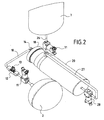
- the actuator shown in FIG. 2 has a compacted shape insofar as the exhaust duct 10 comprises two successive elbows in the same direction, so that the assembly consisting of the oxygen reserve 2, the duct exhaust 10 and the hollow cylindrical body 20 has a generally en shape.
- the reducing unit 4a has a cylindrical shape having a central cylindrical channel having nine grooves 23 longitudinal and rectilinear. Said grooves 23 which each have a rectangular section, are parallel to each other and are regularly distributed around said central channel.
- the reducing unit 4b is traversed longitudinally by seven parallel channels between them one of which is in the central position and the other six are regularly arranged around of said central channel 24 being equidistant from it.
- the cooling circuit 5 comprises a reserve of coolant 22 such as, for example, ethanol and a connecting pipe connecting said reserve 22 to the outlet pipe 26 of the gas.
- the connecting pipe 27 comprises a pyrotechnic valve 28 and originates at the end of the hollow cylindrical body 20 which is opposite that which is screwed on the plug 18 provided with the two initiators 14. Said connecting pipe 27 performs two successive bends in the same direction to lead into the outlet pipe 26 of the gases.
- the expansion chamber 21 is delimited by a hollow cylindrical part 29 closed at one end by a flat circular face 30 and open at the other end, said part 29 being housed in the hollow cylindrical body 20.
- the expansion chamber 21 is partially delimited by the block reducer 4.
- the outlet pipe 26 of the gases comprises at least one pyrotechnic valve 31 located upstream of an inflatable structure 7.
- the mode of operation of this first preferred embodiment of an actuator 1 follows the following steps.
- An electrical signal triggers the two initiators 14 whose combustion will cause the initiation of the relay charge 16.
- the gases thus generated will come to occupy the pyrolysis chamber 17 to heat the surface of the reducing unit 4.
- a new electrical signal will trigger the pyrotechnic valve 11 located on the exhaust channel 10 of the oxygen supply 2 to release said oxygen in said channel 10. Since the relay charge 16 has been put into combustion, it no longer opposes the passage of oxygen which then comes into contact with the reducing block 4 which has been previously heated. There is then a pyrolysis reaction between the oxygen and the reducing unit 4. The hot gases resulting from this reaction pressurize the expansion chamber 21 which will exert a thrust on the cooling liquid 22.
- the pyrotechnic valve 28 carried by the connecting pipe 27 is then opened and the coolant 22 is then expelled by said pipe 27 under the effect of the thrust of the expansion chamber 21. Said liquid 22 reaches the level of the outlet pipe 26 in the form of fine droplets which will cool the hot gases that escape from the expansion chamber 21.
- the pyrotechnic valve 31 of the outlet pipe 26 is triggered to allow the cooled gases to escape and to enter the inflatable structure 7.
- a second preferred embodiment of an actuator 100 comprises an oxygen reserve 102, an ignition system 103, a reducing block 104 of polymethyl methacrylate, a volume buffer 140 and a cylinder 141 provided with a piston 142.
- the oxygen reserve 102 is stored in a hollow cylindrical part 105 having at both ends a flat circular face.
- One of the two planar faces has a central bore serving as a filling orifice and which is closed off by a stopper 106.
- the other planar face comprises a central orifice 107 closed off by a snap seal 108, said orifice 107 constituted by a portion cylindrical extended by a conical portion acting as a primed nozzle.
- the hollow cylindrical part 105 is partially screwed into a hollow cylindrical body 109 comprising the reducing unit 104 and the ignition system 103.
- the connection between said part 105 and said body 109 is hermetic thanks to the insertion of two seals 110a, 110b, between the outer surface of the workpiece 105 and the inner surface of the body 109.
- the workpiece 105 is oriented in the body 109 so that the flat face of said workpiece 105 which has an orifice central 107 closed by a snap seal 108 separates the "reducing block + ignition system" assembly of the oxygen reserve 102.
- the reducing unit 104 is cylindrical and has a central channel having nine longitudinal and rectilinear grooves.
- the ignition system 103 is housed in said central channel and comprises an electrically triggerable initiator 114 and a gas generating relay charge 116 which is wedged between two leaf springs 117a, 117b, said relay load 116 being extended by a nozzle 118 to allow the escape of the gases from the combustion of the relay charge 116 under well-defined conditions.
- the reducing unit 104 is in abutment against an internal shoulder of the hollow cylindrical body 109 and provides a free space 119 with said body 109, said space 119 being in communication with the buffer volume 140 via an outlet pipe 126
- the buffer volume 140 is located in an elongate hollow cylindrical member 143 provided with an outlet 144 connecting said buffer volume 140 to a ram 141, said ram 141 including a piston 142 having an elongate shaft 146 terminating in an enlarged head 147.
- the mode of operation of this second preferred embodiment of an actuator 100 according to the invention is as follows.
- An electrical signal triggers the initiator 114 which will itself burn the relay charge 116.
- the emitted gases will exit the nozzle 118 to come to heat the inner surface of the reducing unit 104 and cause the rupture of the cap 108.
- the pyrolysis reaction between the oxidant and the reducing unit 104 generates gases which will penetrate into the buffer volume 140 through the outlet pipe 126, then out of said volume 140 through the outlet port 144 to exert pressure on the piston 142 of a cylinder 141 to move it.
Abstract
Description
- Le domaine technique de l'invention est celui des actionneurs pyrotechniques ayant pour fonction essentielle soit de gonfler une structure, soit de déplacer une pièce par l'intermédiaire d'un piston. Les actionnaires pyrotechniques selon l'invention sont particulièrement adaptés aux véhicules terrestres pour la mise en oeuvre de système de sécurité de type coussins de protection, aux véhicules aériens pour permettre par exemple, l'ouverture ou la fermeture automatique d'une porte, ainsi qu'aux véhicules spatiaux pour le gonflement de structures favorisant leur atterrissage.
Les actionneurs pyrotechniques ont déjà fait l'objet de plusieurs demandes de brevet.
On peut citer le brevet EP 0 550 321 qui décrit un vérin pyrotechnique à course amortie pouvant être utilisé dans tout type de système d'absorption d'énergie. Ce vérin comporte un générateur de gaz pyrotechnique, un piston, une chambre de combustion de matières pyrotechniques et une chambre et contre-pression ainsi qu'une chambre intermédiaire comprise en ladite chambre de combustion et une extrémité du piston. Un canal relie la chambre intermédiaire à la chambre de contre-pression. Les gaz émis par le générateur mettent sous pression la chambre intermédiaire pour s'opposer au mouvement du piston et ainsi amortir sa course, une partie desdits gaz étant acheminée par le canal vers la chambre de contre-pression.
La demande de brevet FR 2 824 875 concerne un actionneur pyrotechnique possédant un corps, un piston, et une rondelle de retenue dudit piston dans ledit corps. Suivant la position initiale du piston dans le corps, l'actionneur peut, soit exercer une poussée sur un objet en faisant émerger ledit piston dudit corps, soit libérer une pièce mécanique en faisant rentrer le piston dans ledit corps.
Les actionneurs pyrotechniques décrits dans ces deux brevets comportent des charges énergétiques déjà constituées et qui sont susceptibles d'être amorcées en combustion sous l'effet d'une sollicitation accidentelle imprévue, comme, par exemple, une montée en température, l'impact d'un objet qui tombe ou un quelconque frottement.
Dans la suite de la description, l'expression « en position de stockage » correspond à la phase de non fonctionnement de l'actionneur. - Les actionneurs selon l'invention font intervenir des charges énergétiques dissociées impliquant un matériau réducteur et un fluide oxydant qui sont initialement séparés. De cette manière, en position de stockage, les charges énergétiques ne peuvent donc pas réagir à une sollicitation extérieure intempestive, conférant aux actionneurs selon l'invention un haut niveau de sécurité. Lesdits actionneurs sont donc parfaitement adaptés aux véhicules terrestres, aériens ou spatiaux ne tolérant aucun allumage accidentel qui pourrait les mettre hors d'usage, voire les détruire.
- L'objet de la présente invention concerne un actionneur à génération de gaz comprenant un système d'allumage et une charge énergétique caractérisée en ce que ladite charge est constituée par un matériau réducteur et un fluide oxydant dissociés. Autrement dit, en position de stockage, la charge énergétique n'est pas encore constituée. Préférentiellement, le matériau réducteur est solide.
De façon avantageuse, le matériau réducteur est choisi parmi le polyméthacrylate de méthyle, le cariflex, les résines artificielles et naturelles, les métaux et les cires.
Selon une première variante de l'invention, le fluide oxydant est liquide.
Avantageusement, le fluide oxydant est choisi parmi le peroxyde d'oxygène et le nitrate d'hydroxylamine.
Selon une deuxième variante de l'invention, le fluide oxydant est gazeux.
De façon préférentielle, le fluide oxydant est un mélange gazeux constitué principalement d'oxygène. Préférentiellement, le matériau réducteur est constitué par un bloc cylindrique solide traversé longitudinalement par au moins un canal.
De façon avantageuse, le matériau réducteur est traversé longitudinalement par un canal central présentant au moins trois rainures longitudinales, parallèles entre elles et régulièrement réparties autour dudit canal. Avantageusement, le bloc est traversé longitudinalement par sept canaux parallèles entre eux dont l'un est en position centrale et dont les six autres sont régulièrement disposés autour dudit canal central en étant équidistants de celui-ci.
De façon préférentielle, le débit d'oxydant est piloté par une vanne pyrotechnique et une vanne de régulation situées entre la réserve d'oxydant et le matériau réducteur. En fonctionnement, un signal électrique entraîne le déverrouillage de la vanne pyrotechnique pour libérer le fluide oxydant afin qu'il vienne au contact du matériau réducteur et qu'il interagisse avec lui, le débit dudit fluide oxydant étant contrôlé par la vanne de régulation.
Préférentiellement, le système d'allumage comprend un initiateur pyrotechnique et une charge pyrotechnique relais, ledit système étant positionné de sorte que les gaz émis par ladite charge relais vont venir chauffer la surface du matériau réducteur. - De façon avantageuse, l'oxydant est mis au contact du matériau réducteur après que la surface dudit matériau ait été chauffée, pour produire une réaction de pyrolyse, et les gaz ainsi émis sont acheminés vers l'extérieur dudit actionneur au moyen d'une tubulure de sortie. Autrement dit, il est avantageux que la surface du matériau réducteur soit préchauffée avant que l'oxydant soit mis au contact dudit matériau pour produire une réaction de pyrolyse.
Avantageusement, les gaz produits par la réaction de pyrolyse entre le matériau réducteur et l'oxydant sont refroidis au moyen d'un circuit parallèle comprenant un liquide refroidisseur.
De façon préférentielle, le liquide refroidisseur est constitué par de l'éthanol.
Préférentiellement, le circuit comprend successivement une chambre de détente comportant la tubulure de sortie des gaz, une réserve de liquide refroidisseur et une tubulure de liaison entre ladite réserve et ladite tubulure de sortie, ladite tubulure de liaison étant munie d'une vanne pyrotechnique.
De façon avantageuse, la chambre de détente qui possède une paroi mobile au contact du liquide refroidisseur est susceptible de s'agrandir sous l'effet des gaz produits par la pyrolyse, en exerçant une pression sur ledit liquide. Ainsi, lorsque la vanne pyrotechnique de la tubulure de liaison est ouverte, le liquide refroidisseur qui est sous pression, circule dans ladite tubulure pour être acheminé vers la tubulure de sortie. De façon préférentielle, le liquide refroidisseur qui circule dans la tubulure de liaison est diffusé dans la tubulure de sortie sous forme de fines gouttelettes. De cette manière, la diffusion de ces gouttelettes est assimilable à celle que produirait un brumisateur pour refroidir les gaz qui sont expulsés par la tubulure de sortie.
Selon un autre mode de réalisation préféré de l'invention, le débit d'oxydant est piloté par une tuyère amorcée située entre la réserve d'oxydant et le matériau réducteur.
Avantageusement, les gaz émis par la réaction de pyrolyse entre l'oxydant et le matériau réducteur sont acheminés vers un volume tampon débouchant sur un vérin muni d'un piston. De cette manière, les gaz produits lors de la réaction de pyrolyse, vont traverser le volume tampon pour exercer une pression sur le piston du vérin. Le volume tampon est assimilable à une chambre de dépressurisation dans le cas où le vérin serait accidentellement bloqué et risquerait de provoquer l'éclatement de l'actionneur. Ledit volume est dimensionné pour contenir l'ensemble des gaz produits par la réaction de pyrolyse. - Les actionneurs selon l'invention, présentent l'avantage d'être autonomes et d'avoir un encombrement réduit grâce à une grande simplicité de conception. Ils peuvent donc être facilement insérés dans n'importe quel type de dispositif ou d'objet nécessitant les fonctions requises par de tels actionneurs. Ils présentent, de plus, tous les avantages liés à l'utilisation de charges énergétiques, à savoir : fiabilité due à la maîtrise de l'allumage, encombrement réduit dû à la petite taille des charges énergétiques, et grande variabilité des effets due à la diversité des compositions pouvant être retenues pour ces actionneurs.
- On donne ci-après la description détaillée de deux modes de réalisation préférés de l'invention en se référant aux figures 1 à 8.
- La figure 1 est une vue en coupe axiale longitudinale d'un premier mode de réalisation préféré d'un actionneur selon l'invention.
- La figure 2 est une vue en perspective du premier mode de réalisation préféré d'un actionneur selon l'invention ayant une géométrie compactée.
- La figure 3 est une vue agrandie en coupe axiale longitudinale du système d'allumage et du bloc réducteur d'un actionneur selon l'invention.
- La figure 4 est une vue en coupe axiale longitudinale du circuit de refroidissement d'un actionneur selon l'invention.
- La figure 5 est une vue en coupe axiale longitudinale d'un deuxième mode de réalisation préféré d'un actionneur selon l'invention muni d'un vérin.
- La figure 6 est une vue en perspective du deuxième mode de réalisation préféré d'un actionneur selon l'invention sans le vérin.
- La figure 7 est une vue agrandie en coupe axiale longitudinale du système d'allumage et du bloc réducteur du deuxième mode de réalisation préféré d'un actionneur selon l'invention.
- La figure 8 est une vue en perspective d'un premier mode de réalisation préféré d'un bloc de matériau réducteur d'un actionneur selon l'invention.
- La figure 9 est une vue en perspective d'un deuxième mode de réalisation préféré d'un bloc de matériau réducteur d'un actionneur selon l'invention.
- En se référant aux figures 1 et 2, un premier mode de réalisation préféré d'un actionneur 1 selon l'invention comprend une réserve d'oxygène 2, un système d'allumage 3, un bloc réducteur 4 de polyméthacrylate de méthyle, un circuit de refroidissement des gaz 5, un dispositif d'échappement 6 desdits gaz et une structure gonflable 7. La réserve d'oxygène 2 est constituée par une bouteille rigide 8 contenant de l'oxygène sous pression et comportant un canal d'échappement 10 de l'oxygène permettant de relier ladite bouteille 8 au bloc réducteur 4 en passant préalablement à travers le système d'allumage 3. Le canal d'échappement 10 est constitué par une tubulure rigide comportant une vanne pyrotechnique 11 et une vanne de régulation 12, la vanne pyrotechnique 11 étant disposée en amont de la vanne de régulation 12 par rapport à la réserve d'oxygène 2. Le canal 10 possède un canal de dérivation 13 au niveau de la vanne de régulation 12 pour assurer le passage de l'oxygène dans le cas où ladite vanne 12 venait à se fermer dans le cadre de la fonction de régulation de débit.
- En se référant à la figure 3, le système d'allumage 3 comprend deux initiateurs 14 dont chacun est prolongé par un canal 15 débouchant sur une charge relais 16 située dans un espace libre 17 délimité partiellement par le bloc réducteur 4, ledit espace libre 17 jouant.le rôle d'une chambre de pyrolyse lorsque l'actionneur 1 est en phase de fonctionnement. Les deux initiateurs 14 sont situés sur un bouchon 18 possédant un embout central creux 19 destiné à recevoir une extrémité du canal d'échappement 10 relié à la réserve d'oxygène 2. Ledit bouchon 18 est vissé à l'une des deux extrémités d'un corps cylindrique creux 20 contenant successivement et en continuité la charge relais 16, la chambre de pyrolyse 17, le bloc réducteur 4,une chambre de détente 21 et un liquide refroidisseur 22. L'extrémité dudit corps creux 20 autour de laquelle est vissé le bouchon 18 possède un alésage central 52. Ainsi, lorsque le bouchon 18 est vissé, l'embout central creux 19 se retrouve en continuité dudit alésage 52. De cette manière, ledit embout 19 et ledit alésage 52 participent à la communication entre la réserve d'oxygène 2 et le bloc réducteur 4, ladite communication étant toutefois interrompue par la charge relais 16. La chambre de détente 21 comporte une tubulure de sortie 26 des gaz issus de la réaction de pyrolyse entre le bloc réducteur 4 et l'oxygène. L'actionneur présenté à la figure 2 a une forme compactée dans la mesure où le canal d'échappement 10 comporte deux coudes successifs dans le même sens, de sorte que l'ensemble constitué par la réserve d'oxygène 2, le canal d'échappement 10 et le corps cylindrique creux 20 a globalement une forme en ␣.
- En se référant à la figure 8, selon une première variante préférée de l'invention, le bloc réducteur 4a a une forme cylindrique comportant un canal central cylindrique présentant neuf rainures 23 longitudinales et rectilignes. Lesdites rainures 23 qui ont chacune une section rectangulaire, sont parallèles entre elles et sont régulièrement réparties autour dudit canal central.
- Elles confèrent à la section dudit canal un contour étoilé.
- En se référant à la figure 9, selon une deuxième variante préférée de l'invention, le bloc réducteur 4b est traversé longitudinalement par sept canaux parallèles entre eux dont l'un 24 est en position centrale et dont les six autres 25 sont régulièrement disposés autour dudit canal central 24 en étant équidistants de celui-ci.
- En se référant à la figure 4, le circuit de refroidissement 5 comprend une réserve de liquide refroidisseur 22 comme, par exemple, de l'éthanol et une tubulure de liaison reliant ladite réserve 22 à la tubulure de sortie 26 des gaz. La tubulure de liaison 27 comporte une vanne pyrotechnique 28 et prend naissance à l'extrémité du corps cylindrique creux 20 qui est opposée à celle où est vissé le bouchon 18 muni des deux initiateurs 14. Ladite tubulure de liaison 27 effectue deux coudes successifs dans le même sens pour déboucher dans la tubulure de sortie 26 des gaz. La chambre de détente 21 est délimitée par une pièce cylindrique creuse 29 fermée à une extrémité par une face circulaire plane 30 et ouverte à l'autre extrémité, ladite pièce 29 étant logée dans le corps cylindrique creux 20. En position de stockage, l'extrémité ouverte de ladite pièce cylindrique creuse 29 se trouve en butée contre un épaulement interne dudit corps 20, tandis que la face circulaire plane 30 est au contact du liquide refroidisseur 22. La chambre de détente 21 est partiellement délimitée par le bloc réducteur 4. La tubulure de sortie 26 des gaz comporte au moins une vanne pyrotechnique 31 située en amont d'une structure gonflable 7.
- Le mode de fonctionnement de ce premier mode de réalisation préféré d'un actionneur 1 selon l'invention suit les étapes suivantes.
Un signal électrique déclenche les deux initiateurs 14 dont la combustion va provoquer l'initiation de la charge relais 16. Les gaz ainsi générés vont venir occuper la chambre de pyrolyse 17 pour chauffer la surface du bloc réducteur 4. Un nouveau signal électrique va déclencher la vanne pyrotechnique 11 située sur le canal d'échappement 10 de la réserve d'oxygène 2 pour libérer ledit oxygène dans ledit canal 10. Puisque la charge relais 16 a été mise en combustion, elle ne s'oppose plus au passage de l'oxygène qui parvient alors au contact du bloc réducteur 4 qui a été préalablement chauffé. Il se produit alors une réaction de pyrolyse entre l'oxygène et la bloc réducteur 4. Les gaz chauds issus de cette réaction mettent en pression la chambre de détente 21 qui va exercer une poussée sur le liquide refroidisseur 22. La vanne pyrotechnique 28 portée par la tubulure de liaison 27 est ensuite ouverte et le liquide refroidisseur 22 se retrouve alors expulsé par ladite tubulure 27 sous l'effet de la poussée de la chambre de détente 21. Ledit liquide 22 parvient au niveau de la tubulure de sortie 26 sous la forme de fines gouttelettes qui vont refroidir les gaz chauds qui s'échappent de la chambre de détente 21. La vanne pyrotechnique 31 de la tubulure de sortie 26 est déclenchée pour permettre aux gaz refroidis de s'échapper et de s'introduire dans la structure gonflable 7. - En se référant aux figures 5 et 6, un deuxième mode de réalisation préféré d'un actionneur 100 selon l'invention comprend une réserve d'oxygène 102, un système d'allumage 103, un bloc réducteur 104 de polyméthacrylate de méthyle, un volume tampon 140 et un vérin 141 muni d'un piston 142. La réserve d'oxygène 102 est stockée dans une pièce cylindrique creuse 105 possédant à ses deux extrémités une face circulaire plane. L'une des deux faces planes présente un alésage central servant d'orifice de remplissage et qui est obturé par un bouchon 106. L'autre face plane comporte un orifice central 107 obturé par un opercule claquable 108, ledit orifice 107 constitué par une partie cylindrique prolongée par une partie conique jouant le rôle d'une tuyère amorcée. La pièce cylindrique creuse 105 est vissée partiellement dans un corps cylindrique creux 109 comprenant le bloc réducteur 104 et le système d'allumage 103. En se référant à la figure 7, la liaison entre ladite pièce 105 et ledit corps 109 est hermétique grâce à l'insertion de deux joints 110a, 110b, entre la surface externe de la pièce 105 et la surface interne du corps 109. La pièce 105 est orientée dans le corps 109 de manière à ce que la face plane de ladite pièce 105 qui comporte un orifice central 107 obturé par un opercule claquable 108 sépare l'ensemble « bloc réducteur + système d'allumage » de la réserve d'oxygène 102.
Le bloc réducteur 104 est cylindrique et possède un canal central possédant neuf rainures longitudinales et rectilignes. Le système d'allumage 103 est logé dans ledit canal central et comprend un initiateur 114 pouvant être déclenché électriquement et une charge relais 116 productrice de gaz et qui est calée entre deux ressorts à lame 117a, 117b, ladite charge relais 116 étant prolongée par une tuyère 118 pour permettre la fuite des gaz issus de la combustion de la charge relais 116 dans des conditions bien définies. Le bloc réducteur 104 se retrouve en butée contre un épaulement interne du corps cylindrique creux 109 et ménage un espace libre 119 avec ledit corps 109, ledit espace 119 étant en communication avec le volume tampon 140 par l'intermédiaire d'une tubulure de sortie 126. Le volume tampon 140 est situé dans une pièce cylindrique creuse allongée 143 munie d'un orifice de sortie 144 reliant ledit volume tampon 140 à un vérin 141, ledit vérin 141 incluant un piston 142 possédant une tige allongée 146 se terminant par une tête élargie 147. - Le mode de fonctionnement de ce deuxième mode de réalisation préféré d'un actionneur 100 selon l'invention s'effectue comme suit. Un signal électrique déclenche l'initiateur 114 qui va lui-même mettre en combustion la charge relais 116. Les gaz émis vont sortir de la tuyère 118 pour venir chauffer la surface interne du bloc réducteur 104 et provoquer la rupture de l'opercule 108. La réaction de pyrolyse entre l'oxydant et le bloc réducteur 104 génère des gaz qui vont pénétrer dans le volume tampon 140 par l'intermédiaire de la tubulure de sortie 126, puis sortir dudit volume 140 grâce à l'orifice de sortie 144 pour venir exercer une pression sur le piston 142 d'un vérin 141 afin de le déplacer.
Claims (17)
- Actionneur (1,100) à génération de gaz comprenant un système d'allumage (3,103) et une charge énergétique
caractérisée en ce que ladite charge est constituée par un matériau réducteur (4,104) et un fluide oxydant (2,102) dissociés. - Actionneur (1,100) selon la revendication 1
caractérisé en ce que le matériau réducteur (4,104) est choisi parmi le polyméthacrylate de méthyle, le cariflex, les résines artificielles et naturelles, les métaux et les cires. - Actionneur (1,100) selon la revendication 1
caractérisé en ce que le fluide oxydant (2,102) est liquide. - Actionneur (1,100) selon la revendication 3
caractérisé en ce que le fluide oxydant (2,102) est choisi parmi le peroxyde d'oxygène et le nitrate d'hydroxylamine. - Actionneur (1,100) selon la revendication 1
caractérisé en ce que le fluide oxydant (2,102) est gazeux. - Actionneur (1,100) selon la revendication 5
caractérisé en ce que le fluide oxydant (2,102) est un mélange gazeux constitué principalement d'oxygène. - Actionneur (1,100) selon la revendication 1
caractérisé en ce que le matériau réducteur (4,104) est constitué par un bloc cylindrique solide traversé longitudinalement par au moins un canal. - Actionneur (1,100) selon la revendication 7
caractérisé en ce que le bloc (4a) est traversé longitudinalement par un canal central présentant au moins trois rainures (23) longitudinales, parallèles entre elles et régulièrement réparties autour dudit canal. - Actionneur (1,100) selon la revendication 7
caractérisé en ce que la bloc (4b) est traversé longitudinalement par sept canaux parallèles entre eux dont l'un (24) et en position centrale et dont les six autres (25) sont régulièrement disposés autour dudit canal central et étant équidistants de celui-ci. - Actionneur (1) selon la revendication 5 caractérisé en ce que le débit d'oxydant est piloté par une vanne pyrotechnique (11) et une vanne de régulation (12) situées entre la réserve d'oxydant (2) et le matériau réducteur (4).
- Actionneur (1,100) selon la revendication 1
caractérisé en ce que le système d'allumage (3,103) comprend au moins un initiateur pyrotechnique (14,114) et une charge pyrotechnique relais (16,116), ledit système (3 ,103) étant positionné de sorte que les gaz émis par ladite charge relais (16,116) vont venir chauffer la surface du matériau réducteur (4,104). - Actionneur (1,100) selon la revendication 11
caractérisé en ce que l'oxydant (2,102) est mis au contact du matériau réducteur (4,104) après que la surface dudit matériau ait été chauffée, pour produire une réaction de pyrolyse et les gaz ainsi émis sont acheminés vers l'extérieur dudit actionneur (1,100) au moyen d'une tubulure de sortie (26,126). - Actionneur (1) selon la revendication 12 caractérisé en ce que les gaz produits par la réaction de pyrolyse entre le matériau réducteur (4) et l'oxydant (2) sont refroidis au moyen d'un circuit (5) parallèle comprenant un liquide refroidisseur (22) .
- Actionneur (1) selon la revendication 13 caractérisé en ce que le circuit (5) comprend successivement une chambre de détente (21) comportant la tubulure de sortie (26) des gaz, une réserve de liquide refroidisseur (22) et une tubulure de liaison (27) entre ladite réserve (22) et ladite tubulure de sortie (26), ladite tubulure de liaison (27) étant munie d'une vanne pyrotechnique (28).
- Actionneur (1) selon la revendication 14 caractérisé en ce que la chambre de détente (21) qui possède une paroi mobile au contact du liquide refroidisseur (22) est susceptible de s'agrandir sous l'effet des gaz produits par la pyrolyse, en exerçant une pression sur le liquide refroidisseur (22).
- Actionneur (100) selon la revendication 5
caractérisé en ce que le débit d'oxydant (102) est piloté par une tuyère amorcée (107) située entre la réserve d'oxydant (102) et le matériau réducteur (104). - Actionneur (100) selon la revendication 16
caractérisé en ce que les gaz émis par la réaction de pyrolyse entre l'oxydant (102) et le matériau réducteur (104) sont acheminés vers un volume tampon (140) débouchant sur un vérin (141) muni d'un piston (142).
Applications Claiming Priority (1)
| Application Number | Priority Date | Filing Date | Title |
|---|---|---|---|
| FR0409721A FR2875293B1 (fr) | 2004-09-14 | 2004-09-14 | Actionneur hybride muni d'une charge comprenant un oxydant et un reducteur dissocies |
Publications (3)
| Publication Number | Publication Date |
|---|---|
| EP1637511A2 true EP1637511A2 (fr) | 2006-03-22 |
| EP1637511A3 EP1637511A3 (fr) | 2012-12-05 |
| EP1637511B1 EP1637511B1 (fr) | 2018-05-16 |
Family
ID=34952800
Family Applications (1)
| Application Number | Title | Priority Date | Filing Date |
|---|---|---|---|
| EP05291744.0A Active EP1637511B1 (fr) | 2004-09-14 | 2005-08-18 | Actionneur pyrotechnique muni d'une charge comprenant un oxydant et un réducteur dissociés |
Country Status (5)
| Country | Link |
|---|---|
| US (1) | US20060065337A1 (fr) |
| EP (1) | EP1637511B1 (fr) |
| JP (2) | JP4213698B2 (fr) |
| ES (1) | ES2670926T3 (fr) |
| FR (1) | FR2875293B1 (fr) |
Cited By (1)
| Publication number | Priority date | Publication date | Assignee | Title |
|---|---|---|---|---|
| CN110749251A (zh) * | 2019-11-07 | 2020-02-04 | 北京理工大学 | 深空探测器用燃烧驱动型耐高温火工分离装置装药序列 |
Families Citing this family (6)
| Publication number | Priority date | Publication date | Assignee | Title |
|---|---|---|---|---|
| SE531342C2 (sv) * | 2007-07-06 | 2009-03-03 | Bae Systems Bofors Ab | Förfarande och anordning för blandning och initiering av en pyroteknisk sats |
| SE532521C2 (sv) * | 2008-06-11 | 2010-02-16 | Bae Systems Bofors Ab | Verkansanordning för graderad sprängverkan och förfarande därför |
| FR2984307B1 (fr) * | 2011-12-20 | 2014-01-10 | Sme | Procede de generation de gaz de combustion a partir d'un materiau solide precurseur d'oxygene et d'un materiau reducteur solide dissocies et dispositif associe |
| US11912221B2 (en) | 2019-12-05 | 2024-02-27 | Autoliv Asp, Inc. | Actuator devices and assemblies for automotive safety devices |
| JP7431441B2 (ja) | 2020-03-17 | 2024-02-15 | 学校法人 中央大学 | 流体圧アクチュエータ駆動システム及び流体圧アクチュエータ駆動方法 |
| CN111174654A (zh) * | 2020-03-25 | 2020-05-19 | 田永和 | 安全环保气体混合热能膨胀装置及施工方法 |
Citations (2)
| Publication number | Priority date | Publication date | Assignee | Title |
|---|---|---|---|---|
| EP0550321A1 (fr) | 1991-12-31 | 1993-07-07 | Thomson-Brandt Armements | Vérin pyrotechnique à course amortie |
| FR2824875A1 (fr) | 2001-05-21 | 2002-11-22 | Pyroalliance | Actionneur pyrotechnique muni d'une rondelle de retenue |
Family Cites Families (19)
| Publication number | Priority date | Publication date | Assignee | Title |
|---|---|---|---|---|
| CA945123A (en) * | 1970-12-11 | 1974-04-09 | Bernard Doin | Pyrotechnic gas generator |
| US3726088A (en) * | 1971-08-20 | 1973-04-10 | Us Navy | On-demand variable flow closed loop gas generator system with a variable area injector |
| US4527389A (en) * | 1982-06-21 | 1985-07-09 | Thiokol Corporation | Highly soluble, non-hazardous hydroxylammonium salt solutions for use in hybrid rocket motors |
| US4619111A (en) * | 1984-09-07 | 1986-10-28 | Hydril Company | Oilfield closing device operating system |
| DE3621186A1 (de) * | 1986-06-25 | 1988-01-07 | Bbc Brown Boveri & Cie | Verfahren und vorrichtung zum antrieb eines linear bewegbaren bauelementes, insbesondere des beweglichen schaltkontaktes eines elektrischen hochspannungs-leistungsschalters |
| US5509981A (en) * | 1994-02-18 | 1996-04-23 | Mcdonnell Douglas Corporation | Hybrid rocket fuel |
| US5533331A (en) * | 1994-05-25 | 1996-07-09 | Kaiser Marquardt, Inc. | Safe propulsion system for missile divert thrusters and attitude control thrusters and method for use of same |
| US5579636A (en) * | 1995-03-21 | 1996-12-03 | Aerotech, Inc. | Pyrotechnic valve, igniter and combustion preheater for hybrid rocket motors |
| US5847311A (en) * | 1996-10-22 | 1998-12-08 | Trw Vehicle Safety Systems Inc. | Hybrid inflator with crystalline and amorphous block copolymer |
| US6007022A (en) * | 1996-11-08 | 1999-12-28 | Newport News Shipbuilding | Internal combustion catapult |
| US6068290A (en) * | 1997-12-23 | 2000-05-30 | Trw Vehicle Safety System Inc. | Inflator structure |
| IL140921A0 (en) * | 1998-07-22 | 2002-02-10 | Board Or Trustees Of The Lelan | High regression rate hybrid rocket propellants |
| US6684624B2 (en) * | 1998-07-22 | 2004-02-03 | The Board Of Trustees Of The Leland Stanford Junior University | High regression rate hybrid rocket propellants |
| US6125763A (en) * | 1998-08-14 | 2000-10-03 | Environmental Aeroscience Corp. | Integral solid booster and hybrid thrust sustaining system and projectile incorporating the same |
| DE29821232U1 (de) * | 1998-11-26 | 1999-04-01 | Trw Airbag Sys Gmbh & Co Kg | Gasgenerator für ein Sicherheitssystem |
| US6250072B1 (en) * | 1999-07-02 | 2001-06-26 | Quoin, Inc. | Multi-ignition controllable solid-propellant gas generator |
| WO2003027045A2 (fr) * | 2001-09-27 | 2003-04-03 | Vanderbilt University | Actionneur proportionnel entraine avec de l'hypergol/du monergol |
| JP2003089590A (ja) * | 2001-09-11 | 2003-03-28 | Hosoya Fireworks Co Ltd | 固体燃料及びハイブリッド推進薬 |
| US6679049B2 (en) * | 2002-01-22 | 2004-01-20 | Hy Pat Corporation | Hybrid rocket motor having a precombustion chamber |
-
2004
- 2004-09-14 FR FR0409721A patent/FR2875293B1/fr not_active Expired - Fee Related
-
2005
- 2005-08-18 ES ES05291744.0T patent/ES2670926T3/es active Active
- 2005-08-18 EP EP05291744.0A patent/EP1637511B1/fr active Active
- 2005-08-19 US US11/206,989 patent/US20060065337A1/en not_active Abandoned
- 2005-09-14 JP JP2005267204A patent/JP4213698B2/ja not_active Expired - Fee Related
-
2008
- 2008-08-27 JP JP2008217962A patent/JP4988670B2/ja not_active Expired - Fee Related
Patent Citations (2)
| Publication number | Priority date | Publication date | Assignee | Title |
|---|---|---|---|---|
| EP0550321A1 (fr) | 1991-12-31 | 1993-07-07 | Thomson-Brandt Armements | Vérin pyrotechnique à course amortie |
| FR2824875A1 (fr) | 2001-05-21 | 2002-11-22 | Pyroalliance | Actionneur pyrotechnique muni d'une rondelle de retenue |
Cited By (2)
| Publication number | Priority date | Publication date | Assignee | Title |
|---|---|---|---|---|
| CN110749251A (zh) * | 2019-11-07 | 2020-02-04 | 北京理工大学 | 深空探测器用燃烧驱动型耐高温火工分离装置装药序列 |
| CN110749251B (zh) * | 2019-11-07 | 2020-09-04 | 北京理工大学 | 深空探测器用燃烧驱动型耐高温火工分离装置装药序列 |
Also Published As
| Publication number | Publication date |
|---|---|
| FR2875293A1 (fr) | 2006-03-17 |
| EP1637511B1 (fr) | 2018-05-16 |
| US20060065337A1 (en) | 2006-03-30 |
| EP1637511A3 (fr) | 2012-12-05 |
| JP4213698B2 (ja) | 2009-01-21 |
| FR2875293B1 (fr) | 2009-01-16 |
| JP2006084030A (ja) | 2006-03-30 |
| ES2670926T3 (es) | 2018-06-04 |
| JP4988670B2 (ja) | 2012-08-01 |
| JP2008281210A (ja) | 2008-11-20 |
Similar Documents
| Publication | Publication Date | Title |
|---|---|---|
| EP1637511B1 (fr) | Actionneur pyrotechnique muni d'une charge comprenant un oxydant et un réducteur dissociés | |
| EP1705383B1 (fr) | Actionneur pyrotechnique muni d'un organe régulateur de pression | |
| EP2205325B1 (fr) | Dispositif d'ejection d'un fluide a etancheite renforcee | |
| EP2566758B1 (fr) | Dispositif de deverrouillage declenche, reliant deux sous-ensembles detachables | |
| EP2093408B1 (fr) | Réservoir | |
| EP2506938B1 (fr) | Dispositif d'éjection d'un fluide | |
| FR2704924A1 (fr) | Vanne pyrotechnique. | |
| FR2972360A1 (fr) | Dispositif d'extinction d'incendie declenche | |
| EP1496268B1 (fr) | Actionneur pyrotechnique à effet de poussée variable | |
| EP1605995B1 (fr) | Dispositif d´injection sans aiguille a moyens de regulation du niveau de la pression des gaz dans la chambre de combustion | |
| EP3313536B1 (fr) | Extincteur d'incendie | |
| WO2014184505A2 (fr) | Generateur de gaz pyrotechnique | |
| FR3111166A1 (fr) | Actionneur pneumatique pour dispositif d’actionnement spatial | |
| EP1802871B1 (fr) | Actionneur pyrotechnique à effort modulable et à geometrie optimisee | |
| EP2964947B1 (fr) | Dispositif de modulation de section d'ejection de gaz | |
| EP0211703B1 (fr) | Dispositif de fermeture temporaire d'un orifice interne d'un propulseur | |
| EP2444319B1 (fr) | Système de distribution d'un gaz d'actionnement destiné à alimenter un actionneur pneumatique, ensemble d'éjection et procédé de distribution associé | |
| FR2901523A1 (fr) | "generateur de gaz pour dispositif de securite automobile et dispositif qui en est pourvu" | |
| FR2846699A1 (fr) | Dispositif pyrotechnique de dispersion d'un fluide liquide destine a la denaturation de valeurs, utilisant une piece a profil contondant | |
| FR2929126A1 (fr) | Dispositif d'ejection d'un fluide muni d'un dispositif anti-retour | |
| BE458766A (fr) | ||
| FR2920375A1 (fr) | Generateur pyrotechnique de gaz renfermant une reserve de gaz sous presssion |
Legal Events
| Date | Code | Title | Description |
|---|---|---|---|
| PUAI | Public reference made under article 153(3) epc to a published international application that has entered the european phase |
Free format text: ORIGINAL CODE: 0009012 |
|
| AK | Designated contracting states |
Kind code of ref document: A2 Designated state(s): AT BE BG CH CY CZ DE DK EE ES FI FR GB GR HU IE IS IT LI LT LU LV MC NL PL PT RO SE SI SK TR |
|
| AX | Request for extension of the european patent |
Extension state: AL BA HR MK YU |
|
| REG | Reference to a national code |
Ref country code: DE Ref legal event code: R079 Ref document number: 602005053961 Country of ref document: DE Free format text: PREVIOUS MAIN CLASS: C06D0005100000 Ipc: F15B0015190000 |
|
| PUAL | Search report despatched |
Free format text: ORIGINAL CODE: 0009013 |
|
| AK | Designated contracting states |
Kind code of ref document: A3 Designated state(s): AT BE BG CH CY CZ DE DK EE ES FI FR GB GR HU IE IS IT LI LT LU LV MC NL PL PT RO SE SI SK TR |
|
| AX | Request for extension of the european patent |
Extension state: AL BA HR MK YU |
|
| RIC1 | Information provided on ipc code assigned before grant |
Ipc: C06D 5/10 20060101ALI20121101BHEP Ipc: B60R 21/26 20110101ALI20121101BHEP Ipc: C06B 45/00 20060101ALI20121101BHEP Ipc: F15B 15/19 20060101AFI20121101BHEP |
|
| RBV | Designated contracting states (corrected) |
Designated state(s): AT BE BG CH CY LI |
|
| 17P | Request for examination filed |
Effective date: 20130605 |
|
| RBV | Designated contracting states (corrected) |
Designated state(s): AT BE BG CH CY CZ DE DK EE ES FI FR GB GR HU IE IS IT LI LT LU LV MC NL PL PT RO SE SI SK TR |
|
| R17P | Request for examination filed (corrected) |
Effective date: 20050818 |
|
| RBV | Designated contracting states (corrected) |
Designated state(s): AT BE BG CH CY CZ DE DK EE ES FI FR GB GR HU IE IS IT LI LT LU LV MC NL PL PT RO SE SI SK TR |
|
| 17Q | First examination report despatched |
Effective date: 20131018 |
|
| R17P | Request for examination filed (corrected) |
Effective date: 20050818 |
|
| STAA | Information on the status of an ep patent application or granted ep patent |
Free format text: STATUS: EXAMINATION IS IN PROGRESS |
|
| GRAP | Despatch of communication of intention to grant a patent |
Free format text: ORIGINAL CODE: EPIDOSNIGR1 |
|
| STAA | Information on the status of an ep patent application or granted ep patent |
Free format text: STATUS: GRANT OF PATENT IS INTENDED |
|
| INTG | Intention to grant announced |
Effective date: 20171219 |
|
| GRAS | Grant fee paid |
Free format text: ORIGINAL CODE: EPIDOSNIGR3 |
|
| GRAA | (expected) grant |
Free format text: ORIGINAL CODE: 0009210 |
|
| STAA | Information on the status of an ep patent application or granted ep patent |
Free format text: STATUS: THE PATENT HAS BEEN GRANTED |
|
| AK | Designated contracting states |
Kind code of ref document: B1 Designated state(s): AT BE BG CH CY CZ DE DK EE ES FI FR GB GR HU IE IS IT LI LT LU LV MC NL PL PT RO SE SI SK TR |
|
| REG | Reference to a national code |
Ref country code: GB Ref legal event code: FG4D Free format text: NOT ENGLISH |
|
| REG | Reference to a national code |
Ref country code: CH Ref legal event code: EP |
|
| REG | Reference to a national code |
Ref country code: ES Ref legal event code: FG2A Ref document number: 2670926 Country of ref document: ES Kind code of ref document: T3 Effective date: 20180604 |
|
| REG | Reference to a national code |
Ref country code: DE Ref legal event code: R096 Ref document number: 602005053961 Country of ref document: DE |
|
| REG | Reference to a national code |
Ref country code: IE Ref legal event code: FG4D Free format text: LANGUAGE OF EP DOCUMENT: FRENCH |
|
| REG | Reference to a national code |
Ref country code: AT Ref legal event code: REF Ref document number: 999856 Country of ref document: AT Kind code of ref document: T Effective date: 20180615 |
|
| REG | Reference to a national code |
Ref country code: FR Ref legal event code: PLFP Year of fee payment: 14 |
|
| REG | Reference to a national code |
Ref country code: SE Ref legal event code: TRGR |
|
| REG | Reference to a national code |
Ref country code: NL Ref legal event code: MP Effective date: 20180516 |
|
| REG | Reference to a national code |
Ref country code: LT Ref legal event code: MG4D |
|
| PG25 | Lapsed in a contracting state [announced via postgrant information from national office to epo] |
Ref country code: LT Free format text: LAPSE BECAUSE OF FAILURE TO SUBMIT A TRANSLATION OF THE DESCRIPTION OR TO PAY THE FEE WITHIN THE PRESCRIBED TIME-LIMIT Effective date: 20180516 Ref country code: FI Free format text: LAPSE BECAUSE OF FAILURE TO SUBMIT A TRANSLATION OF THE DESCRIPTION OR TO PAY THE FEE WITHIN THE PRESCRIBED TIME-LIMIT Effective date: 20180516 Ref country code: BG Free format text: LAPSE BECAUSE OF FAILURE TO SUBMIT A TRANSLATION OF THE DESCRIPTION OR TO PAY THE FEE WITHIN THE PRESCRIBED TIME-LIMIT Effective date: 20180816 |
|
| PG25 | Lapsed in a contracting state [announced via postgrant information from national office to epo] |
Ref country code: LV Free format text: LAPSE BECAUSE OF FAILURE TO SUBMIT A TRANSLATION OF THE DESCRIPTION OR TO PAY THE FEE WITHIN THE PRESCRIBED TIME-LIMIT Effective date: 20180516 Ref country code: NL Free format text: LAPSE BECAUSE OF FAILURE TO SUBMIT A TRANSLATION OF THE DESCRIPTION OR TO PAY THE FEE WITHIN THE PRESCRIBED TIME-LIMIT Effective date: 20180516 Ref country code: GR Free format text: LAPSE BECAUSE OF FAILURE TO SUBMIT A TRANSLATION OF THE DESCRIPTION OR TO PAY THE FEE WITHIN THE PRESCRIBED TIME-LIMIT Effective date: 20180817 |
|
| REG | Reference to a national code |
Ref country code: AT Ref legal event code: MK05 Ref document number: 999856 Country of ref document: AT Kind code of ref document: T Effective date: 20180516 |
|
| PG25 | Lapsed in a contracting state [announced via postgrant information from national office to epo] |
Ref country code: PL Free format text: LAPSE BECAUSE OF FAILURE TO SUBMIT A TRANSLATION OF THE DESCRIPTION OR TO PAY THE FEE WITHIN THE PRESCRIBED TIME-LIMIT Effective date: 20180516 Ref country code: EE Free format text: LAPSE BECAUSE OF FAILURE TO SUBMIT A TRANSLATION OF THE DESCRIPTION OR TO PAY THE FEE WITHIN THE PRESCRIBED TIME-LIMIT Effective date: 20180516 Ref country code: DK Free format text: LAPSE BECAUSE OF FAILURE TO SUBMIT A TRANSLATION OF THE DESCRIPTION OR TO PAY THE FEE WITHIN THE PRESCRIBED TIME-LIMIT Effective date: 20180516 Ref country code: SK Free format text: LAPSE BECAUSE OF FAILURE TO SUBMIT A TRANSLATION OF THE DESCRIPTION OR TO PAY THE FEE WITHIN THE PRESCRIBED TIME-LIMIT Effective date: 20180516 Ref country code: AT Free format text: LAPSE BECAUSE OF FAILURE TO SUBMIT A TRANSLATION OF THE DESCRIPTION OR TO PAY THE FEE WITHIN THE PRESCRIBED TIME-LIMIT Effective date: 20180516 Ref country code: RO Free format text: LAPSE BECAUSE OF FAILURE TO SUBMIT A TRANSLATION OF THE DESCRIPTION OR TO PAY THE FEE WITHIN THE PRESCRIBED TIME-LIMIT Effective date: 20180516 Ref country code: CZ Free format text: LAPSE BECAUSE OF FAILURE TO SUBMIT A TRANSLATION OF THE DESCRIPTION OR TO PAY THE FEE WITHIN THE PRESCRIBED TIME-LIMIT Effective date: 20180516 |
|
| REG | Reference to a national code |
Ref country code: DE Ref legal event code: R097 Ref document number: 602005053961 Country of ref document: DE |
|
| PLBE | No opposition filed within time limit |
Free format text: ORIGINAL CODE: 0009261 |
|
| STAA | Information on the status of an ep patent application or granted ep patent |
Free format text: STATUS: NO OPPOSITION FILED WITHIN TIME LIMIT |
|
| PG25 | Lapsed in a contracting state [announced via postgrant information from national office to epo] |
Ref country code: MC Free format text: LAPSE BECAUSE OF FAILURE TO SUBMIT A TRANSLATION OF THE DESCRIPTION OR TO PAY THE FEE WITHIN THE PRESCRIBED TIME-LIMIT Effective date: 20180516 |
|
| REG | Reference to a national code |
Ref country code: CH Ref legal event code: PL |
|
| 26N | No opposition filed |
Effective date: 20190219 |
|
| PG25 | Lapsed in a contracting state [announced via postgrant information from national office to epo] |
Ref country code: LU Free format text: LAPSE BECAUSE OF NON-PAYMENT OF DUE FEES Effective date: 20180818 Ref country code: LI Free format text: LAPSE BECAUSE OF NON-PAYMENT OF DUE FEES Effective date: 20180831 Ref country code: CH Free format text: LAPSE BECAUSE OF NON-PAYMENT OF DUE FEES Effective date: 20180831 |
|
| REG | Reference to a national code |
Ref country code: BE Ref legal event code: MM Effective date: 20180831 |
|
| REG | Reference to a national code |
Ref country code: IE Ref legal event code: MM4A |
|
| PG25 | Lapsed in a contracting state [announced via postgrant information from national office to epo] |
Ref country code: SI Free format text: LAPSE BECAUSE OF FAILURE TO SUBMIT A TRANSLATION OF THE DESCRIPTION OR TO PAY THE FEE WITHIN THE PRESCRIBED TIME-LIMIT Effective date: 20180516 |
|
| PG25 | Lapsed in a contracting state [announced via postgrant information from national office to epo] |
Ref country code: IE Free format text: LAPSE BECAUSE OF NON-PAYMENT OF DUE FEES Effective date: 20180818 |
|
| PG25 | Lapsed in a contracting state [announced via postgrant information from national office to epo] |
Ref country code: BE Free format text: LAPSE BECAUSE OF NON-PAYMENT OF DUE FEES Effective date: 20180831 |
|
| PG25 | Lapsed in a contracting state [announced via postgrant information from national office to epo] |
Ref country code: TR Free format text: LAPSE BECAUSE OF FAILURE TO SUBMIT A TRANSLATION OF THE DESCRIPTION OR TO PAY THE FEE WITHIN THE PRESCRIBED TIME-LIMIT Effective date: 20180516 |
|
| PG25 | Lapsed in a contracting state [announced via postgrant information from national office to epo] |
Ref country code: PT Free format text: LAPSE BECAUSE OF FAILURE TO SUBMIT A TRANSLATION OF THE DESCRIPTION OR TO PAY THE FEE WITHIN THE PRESCRIBED TIME-LIMIT Effective date: 20180516 Ref country code: HU Free format text: LAPSE BECAUSE OF FAILURE TO SUBMIT A TRANSLATION OF THE DESCRIPTION OR TO PAY THE FEE WITHIN THE PRESCRIBED TIME-LIMIT; INVALID AB INITIO Effective date: 20050818 |
|
| PG25 | Lapsed in a contracting state [announced via postgrant information from national office to epo] |
Ref country code: CY Free format text: LAPSE BECAUSE OF FAILURE TO SUBMIT A TRANSLATION OF THE DESCRIPTION OR TO PAY THE FEE WITHIN THE PRESCRIBED TIME-LIMIT Effective date: 20180516 |
|
| PG25 | Lapsed in a contracting state [announced via postgrant information from national office to epo] |
Ref country code: IS Free format text: LAPSE BECAUSE OF FAILURE TO SUBMIT A TRANSLATION OF THE DESCRIPTION OR TO PAY THE FEE WITHIN THE PRESCRIBED TIME-LIMIT Effective date: 20180916 |
|
| PGFP | Annual fee paid to national office [announced via postgrant information from national office to epo] |
Ref country code: SE Payment date: 20220819 Year of fee payment: 18 Ref country code: IT Payment date: 20220825 Year of fee payment: 18 Ref country code: GB Payment date: 20220822 Year of fee payment: 18 Ref country code: DE Payment date: 20220819 Year of fee payment: 18 |
|
| PGFP | Annual fee paid to national office [announced via postgrant information from national office to epo] |
Ref country code: FR Payment date: 20220823 Year of fee payment: 18 |
|
| PGFP | Annual fee paid to national office [announced via postgrant information from national office to epo] |
Ref country code: ES Payment date: 20221024 Year of fee payment: 18 |
|
| REG | Reference to a national code |
Ref country code: DE Ref legal event code: R082 Ref document number: 602005053961 Country of ref document: DE Representative=s name: CBDL PATENTANWAELTE GBR, DE |
|
| REG | Reference to a national code |
Ref country code: DE Ref legal event code: R119 Ref document number: 602005053961 Country of ref document: DE |
|
| GBPC | Gb: european patent ceased through non-payment of renewal fee |
Effective date: 20230818 |