EP1636081B1 - Locomotive - Google Patents
Locomotive Download PDFInfo
- Publication number
- EP1636081B1 EP1636081B1 EP04737355A EP04737355A EP1636081B1 EP 1636081 B1 EP1636081 B1 EP 1636081B1 EP 04737355 A EP04737355 A EP 04737355A EP 04737355 A EP04737355 A EP 04737355A EP 1636081 B1 EP1636081 B1 EP 1636081B1
- Authority
- EP
- European Patent Office
- Prior art keywords
- frame
- locomotive according
- middle section
- locomotive
- chords
- Prior art date
- Legal status (The legal status is an assumption and is not a legal conclusion. Google has not performed a legal analysis and makes no representation as to the accuracy of the status listed.)
- Expired - Lifetime
Links
- 230000003137 locomotive effect Effects 0.000 title claims abstract description 36
- 238000001816 cooling Methods 0.000 description 60
- 239000002826 coolant Substances 0.000 description 19
- 238000010276 construction Methods 0.000 description 10
- 238000009423 ventilation Methods 0.000 description 5
- 238000002485 combustion reaction Methods 0.000 description 4
- 230000003068 static effect Effects 0.000 description 3
- 238000010586 diagram Methods 0.000 description 2
- 230000000694 effects Effects 0.000 description 2
- 230000002349 favourable effect Effects 0.000 description 2
- 230000005484 gravity Effects 0.000 description 2
- 238000009434 installation Methods 0.000 description 2
- 238000009413 insulation Methods 0.000 description 2
- 238000012423 maintenance Methods 0.000 description 2
- 238000006073 displacement reaction Methods 0.000 description 1
- 238000002955 isolation Methods 0.000 description 1
- 238000000926 separation method Methods 0.000 description 1
- 239000000758 substrate Substances 0.000 description 1
Images


Classifications
-
- B—PERFORMING OPERATIONS; TRANSPORTING
- B61—RAILWAYS
- B61C—LOCOMOTIVES; MOTOR RAILCARS
- B61C17/00—Arrangement or disposition of parts; Details or accessories not otherwise provided for; Use of control gear and control systems
- B61C17/04—Arrangement or disposition of driving cabins, footplates or engine rooms; Ventilation thereof
-
- B—PERFORMING OPERATIONS; TRANSPORTING
- B60—VEHICLES IN GENERAL
- B60L—PROPULSION OF ELECTRICALLY-PROPELLED VEHICLES; SUPPLYING ELECTRIC POWER FOR AUXILIARY EQUIPMENT OF ELECTRICALLY-PROPELLED VEHICLES; ELECTRODYNAMIC BRAKE SYSTEMS FOR VEHICLES IN GENERAL; MAGNETIC SUSPENSION OR LEVITATION FOR VEHICLES; MONITORING OPERATING VARIABLES OF ELECTRICALLY-PROPELLED VEHICLES; ELECTRIC SAFETY DEVICES FOR ELECTRICALLY-PROPELLED VEHICLES
- B60L2200/00—Type of vehicles
- B60L2200/26—Rail vehicles
Definitions
- the invention relates to a locomotive with a frame and at least one preferably diesel-electric drive unit, wherein the frame has at least two support sections, in the area of the frame is mounted on chassis, and at least one extending between two support sections, preferably downwardly cranked center section ,
- the invention has for its object to provide a space-saving design for a locomotive, which also allows for improved cooling of the engine room.
- the central portion consists essentially of two spaced-apart side parts, each of which has a longitudinally extending lower chord and upper chord and at least one web connecting the lower chord to the upper chord, and at least one drive unit arranged in the central portion of the frame is, wherein the invention provides that the attachment of the at least one drive unit is preferably carried out exclusively on the webs connecting the upper straps with the lower straps.
- the middle portion of the frame is formed as a so-called bridge frame, which consists essentially of a total of four arranged in the longitudinal direction of the rail vehicle longitudinal members.
- two of these longitudinal members form a side part with an upper and a lower flange, by at least one Bridge are interconnected.
- Such a construction allows a variable arrangement of the drive units - both in the horizontal and in the vertical direction - and also offers, as a result of remaining between the lower chords and upper straps clearances, the ability to ventilate the engine room from below, for example, at the bottom of the Engine room arranged, preferably adjustable baffles.
- each middle section of a side part has exactly two webs connecting the lower belt with the upper web, the fastening points, which are preferably designed as consoles, are arranged on these two webs. But also the arrangement of additional vertical webs on which the attachment points are arranged, is conceivable.
- connection between the support portions and the central portion of the frame on the webs which can be both vertically and obliquely, take place.
- cross beams can be arranged between the upper belts and / or the lower belts.
- a further embodiment of the invention provides that the lower chords extend below the support sections, ie, the frame is bent down in the region of its central section, whereby a displacement of the center of gravity is achieved downwards.
- the upper straps above the support sections conveniently in the upper half, preferably in the upper third of the rail vehicle.
- the distance between the lower chords and the upper chords should be so large that two drive units can be arranged one above the other in the engine room.
- a chimney effect In addition to the enormous space savings created by such an arrangement together with the fact that the engine room is essentially limited by the upper and lower chords, with a free space remains between the two lower chords and the two upper straps, a chimney effect.
- This natural ventilation of the engine room can be further supported by arranged on the underside of the engine room and possibly adjustable air deflectors.
- the separation of the engine room from the control room or the driver's cabin, which as a rule has hitherto been carried out by the car body, can be carried out in a simple manner in a rail vehicle according to the invention in that the middle section is delimited by a wall at least on one end side. It does not matter whether this wall between the webs and possibly existing cross members is arranged or whether the webs and possibly existing cross member are part of this wall.
- the engine room limiting side and end walls are designed so that the strength and mounting requirements can be met with sufficient sound insulation at the same time.
- the two bulkheads delimiting the end faces of the machine room increase the torsional rigidity of the locomotive frame over the longitudinal axis of the vehicle and can carry sound and heat insulation as well as line installations for supplying the drive units and, if necessary, consoles for accommodating any auxiliary equipment present.
- all connections to the drive units are preferably realized in a vertical plane.
- another embodiment of the invention provides that at least the top flange of a side part projects beyond the middle section into a support section of the frame has been found to be favorable when the upper flange projecting beyond the middle section into a support section is preferably connected in its end region via a web to the support section.
- such an embodiment brings with it the advantage that in the region of the support section arranged upper flange together with the web connecting this top flange with the support section can simultaneously form the side part of the control room.
- a further preferred embodiment of the invention provides that the central portion is open at the bottom, wherein it has proved to be favorable when the bottom surface formed between the lower chords of the side parts of the central portion to more than 50%, preferably more than 80%, is open ,
- a particularly simple construction results when the bottom surface, with the exception of any existing cross member is completely open, so that the welded frame structure in the area of the engine room is open at the top and bottom of the entire area, i. the engine room is limited only by the side and end walls.
- the distance between at least two cross members is at least 3 m, preferably 5 m. This means that the distance between at least two cross members is greater than the longitudinal extent of the drive unit (s), whereby it is achieved that the at least one drive unit can be arranged below the lower straps protruding in the frame of the locomotive.
- a locomotive with a frame which is arranged on chassis and has a top flange and a bottom flange and at least two preferably diesel-electric drive unit, at least two of these drive units are arranged one above the other.
- the lower drive unit may protrude below the lower flange and / or the upper drive unit via the upper flange.
- a drive unit which according to an embodiment of the invention comprises at least one internal combustion engine and one generator, preferably exactly one internal combustion engine with generator, can be formed in a vertical plane.
- the drive unit may additionally comprise one or more auxiliary units. It has proved to be advantageous if the internal combustion engine, which is designed according to a preferred embodiment of the invention as a diesel engine, together with the generator, any existing auxiliary equipment and line installations and a mounting frame, a pre-assembly forms.
- the mounting frame should be easy or Double-vibration isolation of the drive unit (s) may be formed in the context of the locomotive. The inclusion ofmé Kunststoffleit NASAen in the mounting frame is conceivable.
- the arranged in the central portion of the frame between the side panels drive units thus generate the necessary energy for driving the locomotive, with diesel-electric drives, the electric motors are arranged in a conventional manner in the bogies. But it would also be a mechanical direct drive of the arranged in the central portion of the frame drive units on the wheels conceivable.
- a particularly simple maintenance results further in a rail vehicle with a machine room and a control room, in which the arranged in cabinets control or power devices are arranged, if at least one control cabinet is arranged transversely to the longitudinal axis of the rail vehicle slidably, in such a way that the control cabinet from a side wall of the control room to the outside is displaced or extended.
- the vacated by the extension of the sliding cabinets in the control room space can be used as a mounting gear, which in turn is associated with a large space savings.
- a rail vehicle with a cooling device the at least two preferably arranged in the roof area cooling systems, which lie behind each other in the direction of travel and can be acted upon by a coolant flow, to be specified.
- this difference is to be compensated for by a device for controlling the distribution of the coolant flow to the front or rear cooling systems in the direction of travel.
- louvers that direct the wind to the cooling systems
- the louvers are adjustable via adjusting devices, so that in the direction of travel preferably rear cooling systems can be supported by an additional forced ventilation.
- the device for controlling the distribution of the KLihlkarstromes is set when driving the rail vehicle so that the coolant flow to - seen in the direction of travel - front cooling system is greater than that of the rear cooling system, preferably the coolant flow to in Direction of travel front cooling system increases and at the same time the coolant flow is reduced to the direction of travel behind cooling system.
- the louvers and / or fans arranged in the cooling systems are adjusted so that - seen in the direction of travel - rear cooling system is subjected to an increased air flow.
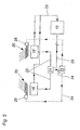
- the in Fig. 1 shown frame 2 of a locomotive has two support sections A, A ', which are mounted on chassis 3 with wheels 17.
- the frame 2 is bent downwards, whereby the driving characteristics of the rail vehicle are improved in particular on poor track systems and in tight curves and the accessibility to the Aggregates is facilitated.
- the side part 4 of the middle section B consists of a lower flange 6 and a top flange 5, which are interconnected by two webs 7.
- the webs 7 extend for reasons of static reasons of the substrate 6 obliquely upwards to the upper flange 5. It would also be possible, the webs 7 extend vertically or from the lower flange 6 obliquely inwards to the upper flange 5.
- the upper straps 5, 5 'and lower straps 6, 6' limit the machine room 11 laterally or up and down.
- the free spaces enclosing the lower straps 6, 6 'or the upper straps 5, 5' between them may remain free for reasons of better ventilation.
- the end faces of the central portion B, which are formed by the webs 7 and possibly existing cross members can be closed, for example by structure-supporting walls 9, so that the engine room 11 is closed in the front and rear direction, while the bottom of the machine room 11 and the top of the engine room 11 - except for selective rain protection devices for the drive units - is completely open.
- the upper flange 5 of the side part 4 is longer than the lower flange 6 and projects beyond the central portion B in the support sections A, A 'of the frame 2, and is in its two end regions via webs 18 with side rails 19 of the support sections A. 'A' connected. These projecting into the support sections A, A 'parts of the upper flange 5 together with the webs 18, the side parts of the sound chamber 12. At the end faces of the frame 2 as usual buffer 16 are arranged.
- Fig. 2a shows that the support section A has two lateral side members 19, which are interconnected via a cross member 8.
- the frame 2 in the support section A plate-shaped.
- the Fig. 2c shows in principle a cross section through the machine room 11 with drive units 10, 10 'arranged therein.
- the upper belts 5, 5' it is necessary for the upper belts 5, 5' to be arranged in the upper half, preferably in the uppermost third of the height of the rail vehicle 1.
- the drive units 10, 10 ' are mounted on the lower chords 6, 6' and the upper chords 5, 5 'of the frame 2 (not shown).
- the free space of the machine room 11 remaining laterally or above the drive units 10, 10 'can for example, be utilized for the arrangement of exhaust systems.
- Fig. 3a and 3b show the front in the direction of travel F support portion A and a part of the central portion B of the frame 2 in side view and top view.
- a wall 9 separates the engine room 11 from the control room 12, the lateral boundary is made by a side wall 14.
- a first cooling system 15 of a cooling device is arranged in the roof region of the carriage structure arranged above the support section A.
- a second cooling system 15 'of the cooling device is arranged in the roof region of the support section A' arranged behind the direction of travel in the direction of travel ( Fig. 4a ).
- louvers 20 are arranged, which may be formed, for example, as air baffles or fans, wherein at the front in the direction of travel cooling system 15, the wind is fed to the front side, while the introduction of the wind in the direction of travel F rear cooling system 15 'takes place mainly via the louver 20.
- switch cabinets 13 are arranged displaceably transversely to the longitudinal direction of the rail vehicle in the control room 12.
- this has the advantage that maintenance or service operations on the control cabinets 13 can be partly carried out from the outside, on the other hand
- Such a construction has the advantage of an enormous space savings, since the necessary space for movement to wait for the fixed cabinets 13 'in operation of the rail vehicle provides the space for the inserted cabinets 13.
- Fig. 5 is schematically illustrated the principle of operation of a cooling device.
- the invention is based on the consideration that, as a result of the use of the airstream cooling medium for the cooling systems in the direction of travel front cooling system 15 must provide a much larger proportion of the overall performance of the cooling device, since the rear lying in the direction of travel cooling system 15 'naturally with less wind and in addition usually with the heated exhaust air from the engine room or the exhaust system is applied.
- the front and rear cooling system there are in principle two options.
- the coolant flow can be distributed differently to the front or rear cooling system.
- the cooling device has a control device 22 which is connected via a control line 24 to a valve 21 and outputs control signals to the valve 21.
- the valve 21 is connected on the input side via a coolant line 23 to a motor 10.
- the hot coolant flow flowing from the engine 10 to the valve 21 is divided differently between the cooling systems 15, 15 'as a function of the signal from the control device 22.
- the hot coolant thus flows through the coolant line 23 to the respective cooling systems 15, 15 ', is cooled there and subsequently fed back to the engine 10, so that the coolant circuit closes.
- One possibility therefore, is to supply the front cooling system 15, which is more powerful than the rear cooling system 15 'due to the larger amount of cold air flow, to a larger amount of coolant flow to be cooled and thus to relieve the less powerful rear cooling system 15'.
- louvers 20 are adjustable by means of an adjusting device 25, depending on the operating state, in particular the direction of travel, of the rail vehicle, wherein the adjusting device 25 is connected via a control line 24 to the control device 22.
- the adjusting device 25 is connected via a control line 24 to the control device 22.
- Optimal control of the cooling device that is to say an optimal distribution of the cooling power of the cooling device to be provided on the two cooling systems 15, 15 'as a function of their power level, can be achieved by a combination of both measures. That is, on the one hand in the direction of travel front cooling system 15 is acted upon by the controller 22 on the one hand with a larger coolant flow while the rear in the direction of travel cooling system 15 'applied via the adjustable louvers 20 with increased airstream.
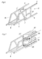
- Fig. 6 shows a perspective view of a frame 2 according to the invention, from which it can be seen that the downwardly cranked center portion of the frame is separated from the front support portion by a bulkhead 9. Between the upper chords 5, 5 'and the lower chords 6, 6' of the two side parts 4, 4 'are in addition to the oblique webs 7, 7' additionally vertically extending webs 27, 27 'are arranged.
- these vertical connecting webs 27, 27 ' serve the arrangement of mounting brackets 26, 26'.
- the vertical webs 27, 27 ' which can be arranged both on the oblique webs 7, 7', the vertical webs 27, 27 'and on the upper and lower chords, the drive units 10 in the central portion of the Frame mounted. It has proved to be advantageous if all arranged on the drive units 10, 10 'connections are formed lying in a plane.
- a basic idea of the invention is a To provide a frame structure for a machine frame of a locomotive, which is substantially open at the top and bottom and in this way in addition to a good ventilation allows a particularly simple design.
- locomotives equipped with this frame according to the invention can be designed with only four axles, so that the total weight of such a powerful locomotive is approximately 80 t, while the usually equipped with six axes locomotives of this power class, the state of the art, a Total weight between 120 and 160 t.
Landscapes
- Engineering & Computer Science (AREA)
- Automation & Control Theory (AREA)
- Transportation (AREA)
- Mechanical Engineering (AREA)
- Electric Propulsion And Braking For Vehicles (AREA)
- Arrangement Or Mounting Of Propulsion Units For Vehicles (AREA)
- Diaphragms For Electromechanical Transducers (AREA)
- Inorganic Insulating Materials (AREA)
- Lubricants (AREA)
- Body Structure For Vehicles (AREA)
Abstract
Description
Die Erfindung betrifft eine Lokomotive, mit einem Rahmen und wenigstens einer vorzugsweise diesel-elektrischen Antriebseinheit, wobei der Rahmen wenigstens zwei Auflageabschnitte, in deren Bereich der Rahmen auf Fahrgestellen gelagert ist, und wenigstens einen sich zwischen zwei Auflageabschnitten erstreckenden, vorzugsweise nach unten durchgekröpften Mittelabschnitt aufweist.The invention relates to a locomotive with a frame and at least one preferably diesel-electric drive unit, wherein the frame has at least two support sections, in the area of the frame is mounted on chassis, and at least one extending between two support sections, preferably downwardly cranked center section ,
Es sind bereits Schienenfahrzeuge zur Personenförderung bekannt, bei denen die Kröpfung der Rahmenplatte einerseits dazu dient, den Schwerpunkt des Schienenfahrzeuges nach unten zu verlegen und auf diese Weise ein Entgleisen des Schienenfahrzeuges zu verhindern und andererseits geringe Einstiegshöhen ermöglicht (siehe z.B
Die Erfindung hat es sich zur Aufgabe gestellt, eine platzsparende Konstruktion für eine Lokomotive zu schaffen, die gleichzeitig eine verbesserte Kühlung des Maschinenraumes erlaubt.The invention has for its object to provide a space-saving design for a locomotive, which also allows for improved cooling of the engine room.
Erfindungsgemäß wird dies dadurch erreicht, dass der Mittelabschnitt im Wesentlichen aus zwei voneinander beabstandeten Seitenteilen besteht, von denen jeder einen in Längsrichtung verlaufenden Untergurt und Obergurt und mindestens einen den Untergurt mit dem Obergurt verbindenden Steg aufweist, und dass wenigstens eine Antriebseinheit im Mittelabschnitt des Rahmens angeordnet ist, wobei die Erfindung vorsieht, dass die Befestigung der mindestens einen Antriebseinheit vorzugsweise ausschließlich an den die Obergurte mit den Untergurten verbindenden Stegen erfolgt.According to the invention this is achieved in that the central portion consists essentially of two spaced-apart side parts, each of which has a longitudinally extending lower chord and upper chord and at least one web connecting the lower chord to the upper chord, and at least one drive unit arranged in the central portion of the frame is, wherein the invention provides that the attachment of the at least one drive unit is preferably carried out exclusively on the webs connecting the upper straps with the lower straps.
Im Gegensatz zu den bekannten plattenförmigen Rahmenmittelabschnitten ist der erfindungsgemäße Mittelabschnitt des Rahmens als sogenannter Brückenrahmen ausgebildet, der im wesentlichen aus insgesamt vier in Längsrichtung des Schienenfahrzeuges angeordneten Längsträgern besteht. Jeweils zwei dieser Längsträger bilden einen Seitenteil mit einem Ober- und einem Untergurt, die durch mindestens einen Steg miteinander verbunden sind. Eine derartige Konstruktion erlaubt eine variable Anordnung der Antriebseinheiten - sowohl in horizontaler als auch in vertikaler Richtung - und bietet zudem, in Folge der zwischen den Untergurten und Obergurten verbleibenden Freiräume, die Möglichkeit, den Maschinenraum von unten zu belüften, beispielsweise mit an der Unterseite des Maschinenraums angeordneten, vorzugsweise verstellbaren Luftleitblechen.In contrast to the known plate-shaped frame central portions of the invention, the middle portion of the frame is formed as a so-called bridge frame, which consists essentially of a total of four arranged in the longitudinal direction of the rail vehicle longitudinal members. In each case two of these longitudinal members form a side part with an upper and a lower flange, by at least one Bridge are interconnected. Such a construction allows a variable arrangement of the drive units - both in the horizontal and in the vertical direction - and also offers, as a result of remaining between the lower chords and upper straps clearances, the ability to ventilate the engine room from below, for example, at the bottom of the Engine room arranged, preferably adjustable baffles.
Um einen ungehinderten Ausbau der diesel-elektrischen Antriebseinheit(en) nach oben und unten zu erlauben, ist gemäß einer weiteren Ausführungsform der Erfindung vorgesehen, dass an wenigstens zwei sich in Bezug auf die Längsachse des Rahmens gegenüberliegenden Stegen Befestigungskonsolen zur Montage des/der Antriebseinheit(en) angeordnet bzw. anordenbar sind.In order to allow unimpeded removal of the diesel-electric drive unit (s) up and down, according to a further embodiment of the invention provides that on at least two opposite with respect to the longitudinal axis of the frame webs mounting brackets for mounting the / the drive unit ( En) are arranged or can be arranged.
Weist, wie in einem weiteren Ausführungsbeispiel der Erfindung vorgesehen, jeder Mittelabschnitt eines Seitenteiles genau zwei den Untergurt mit dem Obergut verbindende Stege auf, sind die vorzugsweise als Konsolen ausgeführten Befestigungspunkte an diesen beiden Stegen angeordnet. Aber auch die Anordnung zusätzlicher vertikaler Stege, an denen die Befestigungspunkte angeordnet sind, ist denkbar.If, as provided in a further exemplary embodiment of the invention, each middle section of a side part has exactly two webs connecting the lower belt with the upper web, the fastening points, which are preferably designed as consoles, are arranged on these two webs. But also the arrangement of additional vertical webs on which the attachment points are arranged, is conceivable.
In der Regel wird die Verbindung zwischen den Auflageabschnitten und dem Mittelabschnitt des Rahmens an den Stegen, die sowohl vertikal als auch schräg ausgerichtet sein können, erfolgen. Um die statischen Eigenschaften der erfindungsgemäßen Rahmenkonstruktion zu verbessern, können gemäß einem weiteren Ausführungsbeispiel der Erfindung zwischen den Obergurten und/oder den Untergurten Querträger angeordnet sein. Dadurch erhält man eine Rahmenkonstruktion, bei der die Seitenteile, die einen Obergurt, einen Untergurt und wenigstens einen Steg aufweisen, über Querträger miteinander verbunden sind, was gleichzusetzen ist mit einem Mittelabschnitt eines Rahmens, der im wesentlichen aus einem Ober- und einem Unterteil besteht, wobei sowohl das Ober- als auch das Unterteil jeweils zwei durch Querträger verbundene Seitenträger aufweisen und bei dem das Ober- und das Unterteil über vertikal verlaufende Stege miteinander verbunden sind.In general, the connection between the support portions and the central portion of the frame on the webs, which can be both vertically and obliquely, take place. In order to improve the static properties of the frame construction according to the invention, according to a further embodiment of the invention, cross beams can be arranged between the upper belts and / or the lower belts. This results in a frame construction in which the side parts, which have a top flange, a bottom flange and at least one web, are interconnected by cross members, which is equivalent to a central portion of a frame, which consists essentially of an upper and a lower part, wherein both the upper and the lower part each have two side beams connected by cross members and in which the upper and the lower part are connected to each other via vertically extending webs.
Eine weitere Ausführungsform der Erfindung sieht vor, dass die Untergurte unterhalb der Auflageabschnitte verlaufen, d. h., der Rahmen ist im Bereich seines Mittelabschnittes nach unten durchgekröpft, wodurch eine Verlagerung des Schwerpunktes nach unten erreicht wird.A further embodiment of the invention provides that the lower chords extend below the support sections, ie, the frame is bent down in the region of its central section, whereby a displacement of the center of gravity is achieved downwards.
Eine Verringerung des Platzbedarfes wird dann erreicht, wenn gemäß einem besonders bevorzugten Ausführungsbeispiel der Erfindung die Obergurte oberhalb der Auflageabschnitte verlaufen, günstigerweise in der oberen Hälfte, vorzugsweise im obersten Drittel des Schienenfahrzeuges. Anders ausgedrückt heißt das, dass der Abstand zwischen den Untergurten und den Obergurten so groß sein sollte, dass zwei Antriebseinheiten übereinander im Maschinenraum angeordnet werden können. Neben der enormen Platzersparnis entsteht durch eine derartige Anordnung zusammen mit dem Umstand, dass der Maschinenraum im wesentlichen durch die Ober- und die Untergurte begrenzt wird, wobei zwischen den zwei Untergurten und den zwei Obergurten jeweils ein Freiraum verbleibt, eine Kaminwirkung. Diese natürliche Belüftung des Maschinenraumes kann durch an der Unterseite des Maschinenraumes angeordnete und gegebenenfalls verstellbare Luftleitbleche weiter unterstützt werden.A reduction in the space required is achieved when according to a particularly preferred embodiment of the invention, the upper straps above the support sections, conveniently in the upper half, preferably in the upper third of the rail vehicle. In other words, the distance between the lower chords and the upper chords should be so large that two drive units can be arranged one above the other in the engine room. In addition to the enormous space savings created by such an arrangement together with the fact that the engine room is essentially limited by the upper and lower chords, with a free space remains between the two lower chords and the two upper straps, a chimney effect. This natural ventilation of the engine room can be further supported by arranged on the underside of the engine room and possibly adjustable air deflectors.
Die in der Regel bisher durch den Wagenaufbau erfolgte Abtrennung des Maschinenraumes vom Schaltraum bzw. der Fahrerkabine kann bei einem erfindungsgemäßen Schienenfahrzeug in einfacher Weise dadurch erfolgen, dass der Mittelabschnitt wenigstens an einer Stirnseite von einer Wand begrenzt ist. Dabei spielt es keine Rolle, ob diese Wand zwischen den Stegen und allenfalls vorhandenen Querträgern angeordnet ist oder ob die Stege und allenfalls vorhandene Querträger Teil dieser Wand sind. Die den Maschinenraum begrenzenden Seiten- und Stirnwände sind so ausgeführt, dass die Festigkeits- und Montageanforderungen bei gleichzeitig ausreichender Schallisolation erfüllt werden können. Die beiden die Stirnseiten des Maschinenraumes begrenzenden Schottwände erhöhen dabei die Torsionssteifigkeit des Lokomotivenrahmens über die Fahrzeuglängsachse und können Schall- und Wärmeisolationen sowie Leitungsinstallationen zur Versorgung der Antriebseinheiten und gegebenfalls Konsolen zur Aufnahme eventuell vorhandener Hilfsaggregate tragen. Dabei werden alle Anschlüsse zu den Antriebseinheiten vorzugsweise in einer vertikalen Ebene realisiert.The separation of the engine room from the control room or the driver's cabin, which as a rule has hitherto been carried out by the car body, can be carried out in a simple manner in a rail vehicle according to the invention in that the middle section is delimited by a wall at least on one end side. It does not matter whether this wall between the webs and possibly existing cross members is arranged or whether the webs and possibly existing cross member are part of this wall. The engine room limiting side and end walls are designed so that the strength and mounting requirements can be met with sufficient sound insulation at the same time. The two bulkheads delimiting the end faces of the machine room increase the torsional rigidity of the locomotive frame over the longitudinal axis of the vehicle and can carry sound and heat insulation as well as line installations for supplying the drive units and, if necessary, consoles for accommodating any auxiliary equipment present. In this case, all connections to the drive units are preferably realized in a vertical plane.
Um sicherzustellen, dass die erfindungsgemäße Rahmenkonstruktion für ein Schienenfahrzeug den enormen Beanspruchungen, denen sie ausgesetzt ist, Stand hält, sieht ein weiteres Ausführungsbeispiel der Erfindung vor, dass wenigstens der Obergurt eines Seitenteiles über den Mittelabschnitt in einen Auflageabschnitt des Rahmens ragt, wobei es sich als günstig herausgestellt hat, wenn der über den Mittelabschnitt in einen Auflageabschnitt ragende Obergurt vorzugsweise in seinem Endbereich über einen Steg mit dem Auflageabschnitt verbunden ist. Neben den statischen Verbesserungen bringt eine derartige Ausführungsform den Vorteil mit sich, dass der im Bereich des Auflageabschnittes angeordnete Obergurt zusammen mit dem diesen Obergurt mit dem Auflageabschnitt verbindenden Steg gleichzeitig den Seitenteil des Schaltraumes bilden kann.To ensure that the frame construction according to the invention for a rail vehicle withstands the enormous stresses to which it is subjected, another embodiment of the invention provides that at least the top flange of a side part projects beyond the middle section into a support section of the frame has been found to be favorable when the upper flange projecting beyond the middle section into a support section is preferably connected in its end region via a web to the support section. In addition to the static improvements, such an embodiment brings with it the advantage that in the region of the support section arranged upper flange together with the web connecting this top flange with the support section can simultaneously form the side part of the control room.
Ein weiteres bevorzugtes Ausführungsbeispiel der Erfindung sieht vor, dass der Mittelabschnitt nach unten offen ist, wobei es sich als günstig erwiesen hat, wenn die zwischen den Untergurten der Seitenteile des Mittelabschnittes gebildete Bodenfläche zu mehr als 50 %, vorzugsweise mehr als 80%, offen ist. Eine besonders einfache Konstruktion ergibt sich dabei, wenn die Bodenfläche, ausgenommen eventuell vorhandene Querträger, vollständig offen ist, sodass die geschweißte Rahmenstruktur im Bereich des Maschinenraumes unten und oben vollflächig offen ist, d.h. der Maschinenraum wird nur durch die Seiten- und Stirnwände begrenzt. Gemäß einem bevorzugten Ausführungsbeispiel ist dabei vorgesehen, dass der Abstand zwischen wenigstens zwei Querträgern mindestens 3 m, vorzugsweise 5 m, beträgt. Das bedeutet, dass der Abstand zwischen wenigstens zwei Querträgern größer ist als die Längserstreckung der Antriebseinheit(en), wodurch erreicht wird, dass die mindestens eine Antriebseinheit unter die Untergurte hinunterragend im Rahmen der Lokomotive angeordnet werden kann.A further preferred embodiment of the invention provides that the central portion is open at the bottom, wherein it has proved to be favorable when the bottom surface formed between the lower chords of the side parts of the central portion to more than 50%, preferably more than 80%, is open , A particularly simple construction results when the bottom surface, with the exception of any existing cross member is completely open, so that the welded frame structure in the area of the engine room is open at the top and bottom of the entire area, i. the engine room is limited only by the side and end walls. According to a preferred embodiment, it is provided that the distance between at least two cross members is at least 3 m, preferably 5 m. This means that the distance between at least two cross members is greater than the longitudinal extent of the drive unit (s), whereby it is achieved that the at least one drive unit can be arranged below the lower straps protruding in the frame of the locomotive.
Es kann weiter vorgesehen sein, dass bei einer Lokomotive mit einem Rahmen, der auf Fahrgestellen angeordnet ist und einen Obergurt und einen Untergurt sowie wenigstens zwei vorzugsweise diesel-elektrische Antriebseinheit aufweist, wenigstens zwei dieser Antriebseinheiten übereinander angeordnet sind. Dabei kann die untere Antriebseinheit unter den Untergurt und/oder die obere Antriebseinheit über den Obergurt hinausragen. Dadurch wird neben einer Schwerpunktsverlagerung nach unten eine besonders wartungsfreundliche Konstruktion erreicht.It can further be provided that in a locomotive with a frame which is arranged on chassis and has a top flange and a bottom flange and at least two preferably diesel-electric drive unit, at least two of these drive units are arranged one above the other. In this case, the lower drive unit may protrude below the lower flange and / or the upper drive unit via the upper flange. As a result, in addition to a shift of emphasis down to a particularly maintenance-friendly construction is achieved.
Zur einfachen Montage der Antriebseinheit(en) im Rahmen können alle Anschlüsse einer Antriebseinheit, die gemäß einem Ausführungsbeispiel der Erfindung wenigstens einen Verbrennungsmotor und einen Generator, vorzugsweise genau einen Verbrennungsmotor mit Generator umfasst, in einer vertikalen Ebene ausgebildet sein. Neben dem Verbrennungsmotor und dem Generator kann die Antriebseinheit zusätzlich ein oder mehrere Hilfsaggregate umfassen. Dabei hat es sich als günstig herausgestellt, wenn der Verbrennungsmotor, der gemäß einem bevorzugten Ausführungsbeispiel der Erfindung als Dieselmotor ausgebildet ist, zusammen mit dem Generator, eventuell vorhandener Hilfsaggregate und Leitungsinstallationen sowie einem Montagerahmen, eine Vormontageeinheit bildet. Dabei sollte der Montagerahmen zur einfach- oder doppeltschwingungsisolierten Befestigung der Antriebseinheit(en) im Rahmen der Lokomotive ausgebildet sein. Auch die Aufnahme von Kühlluftleiteinrichtungen im Montagerahmen ist denkbar.For easy mounting of the drive unit (s) in the frame, all connections of a drive unit, which according to an embodiment of the invention comprises at least one internal combustion engine and one generator, preferably exactly one internal combustion engine with generator, can be formed in a vertical plane. In addition to the internal combustion engine and the generator, the drive unit may additionally comprise one or more auxiliary units. It has proved to be advantageous if the internal combustion engine, which is designed according to a preferred embodiment of the invention as a diesel engine, together with the generator, any existing auxiliary equipment and line installations and a mounting frame, a pre-assembly forms. The mounting frame should be easy or Double-vibration isolation of the drive unit (s) may be formed in the context of the locomotive. The inclusion of Kühlluftleiteinrichtungen in the mounting frame is conceivable.
Die im Mittelabschnitt des Rahmens zwischen den Seitenteilen angeordneten Antriebseinheiten erzeugen also die für den Antrieb der Lokomotive notwendige Energie, wobei bei diesel-elektrischen Antrieben die Elektromotoren in an sich bekannter Weise im Bereich der Drehgestelle angeordnet sind. Es wäre aber auch ein mechanischer Direktantrieb von den im Mittelabschnitt des Rahmens angeordneten Antriebseinheiten auf die Räder denkbar.The arranged in the central portion of the frame between the side panels drive units thus generate the necessary energy for driving the locomotive, with diesel-electric drives, the electric motors are arranged in a conventional manner in the bogies. But it would also be a mechanical direct drive of the arranged in the central portion of the frame drive units on the wheels conceivable.
Eine besonders einfache Wartung ergibt sich weiters bei einem Schienenfahrzeug mit einem Maschinenraum und einem Schaltraum, in dem die in Schaltschränken angeordneten Steuerungs- bzw. Leistungseinrichtungen angeordnet sind, dann, wenn wenigstens ein Schaltschrank quer zur Längsachse des Schienenfahrzeuges verschiebbar angeordnet ist, und zwar derart, dass der Schaltschrank aus einer Seitenwand des Schaltraumes nach außen verschiebbar bzw. ausziehbar ist. Der durch das Ausfahren der verschiebbaren Schaltschränke im Schaltraum frei gewordene Platz kann dabei als Montagegang benutzt werden, was wiederum mit einer großen Platzersparnis verbunden ist.A particularly simple maintenance results further in a rail vehicle with a machine room and a control room, in which the arranged in cabinets control or power devices are arranged, if at least one control cabinet is arranged transversely to the longitudinal axis of the rail vehicle slidably, in such a way that the control cabinet from a side wall of the control room to the outside is displaced or extended. The vacated by the extension of the sliding cabinets in the control room space can be used as a mounting gear, which in turn is associated with a large space savings.
Weiters soll ein Schienenfahrzeug mit einer Kühleinrichtung, die wenigstens zwei vorzugsweise im Dachbereich angeordnete Kühlanlagen, die in Fahrtrichtung hintereinander liegen und mit einem Kühlmittelstrom beaufschlagbar sind, aufweist, angegeben werden.Furthermore, a rail vehicle with a cooling device, the at least two preferably arranged in the roof area cooling systems, which lie behind each other in the direction of travel and can be acted upon by a coolant flow, to be specified.
Durch die Nutzung des Fahrtwindes ergeben sich fahrtrichtungsabhängige Unterschiede in der Kühlleistung zwischen der in Fahrtrichtung vorne bzw. hinten liegenden Kühlanlage. Erfindungsgemäß soll dieser Unterschied durch eine Einrichtung zur Steuerung der Verteilung des Kühlmittelstromes auf die in Fahrtrichtung vorne bzw. hinten liegenden Kühlanlagen ausgeglichen werden.By using the airstream, there are differences in the cooling performance between the front and rear cooling system in the direction of travel depending on the direction of travel. According to the invention, this difference is to be compensated for by a device for controlling the distribution of the coolant flow to the front or rear cooling systems in the direction of travel.
Bei einem gattungsgemäßen Schienenfahrzeug, das Luftleiteinrichtungen aufweist, die den Fahrtwind auf die Kühlanlagen leiten, kann vorgesehen sein, dass die Luftleiteinrichtungen über Verstelleinrichtungen verstellbar ausgebildet sind, sodass die in Fahrtrichtung vorzugsweise hinten liegenden Kühlanlagen, durch eine zusätzliche Zwangsbelüftung unterstützt werden können.In a generic rail vehicle that has louvers that direct the wind to the cooling systems, it can be provided that the louvers are adjustable via adjusting devices, so that in the direction of travel preferably rear cooling systems can be supported by an additional forced ventilation.
Es kann vorgesehen sein, eine Kühleinrichtung eines Schienenfahrzeuges derart zu betreiben, dass die Einrichtung zur Steuerung der Verteilung des Kühlmittelstromes und/oder die Luftleiteinrichtungen und/oder bei den Kühlanlagen vorgesehene Ventilatoren je nach Bewegungszustand, insbesondere der Fahrtrichtung, des Schienenfahrzeugs unterschiedlich eingestellt wird bzw. werden. Dabei geht man von der Überlegung aus, den Anteil der vorderen bzw. hinteren Kühlanlage an der Gesamtkühlleistung zu steuern, indem man entweder die Leistungsstärke der vorzugsweise hinteren Kühlanlagen durch eine zusätzliche Zwangsbelüftung erhöht oder indem man den Kühlmittelstrom unterschiedlich zwischen den in ihrer Leistungsstärke - je nach Fahrtrichtung - verschiedenen vorderen bzw. hinteren Kühlanlagen aufteilt.It can be provided to operate a cooling device of a rail vehicle such that the device for controlling the distribution of the coolant flow and / or the louvers and / or provided in the cooling fans depending on the state of motion, in particular the direction of travel, the rail vehicle is set differently or become. It is based on the idea of controlling the proportion of the front or rear cooling system to the total cooling capacity by either the performance of the preferred rear cooling systems increased by an additional forced ventilation or by varying the coolant flow between the in their performance - depending on Direction of travel - different front and rear cooling systems divides.
Dies kann in einfacher Weise dadurch erfolgen, dass bei Fahrt des Schienenfahrzeugs die Einrichtung zur Steuerung der Verteilung des KLihlmittelstromes so eingestellt wird, dass der Kühlmittelstrom zur - in Fahrtrichtung gesehen - vorderen Kühlanlage größer ist als der zur hinteren Kühlanlage, wobei vorzugsweise der Kühlmittelstrom zur in Fahrtrichtung vorne liegenden Kühlanlage erhöht und gleichzeitig in gleichem Maße der Kühlmittelstrom zur in Fahrtrichtung hinten liegenden Kühlanlage reduziert wird. Derselbe Effekt wird gemäß einem weiteren Ausführungsbeispiel dann erreicht, wenn bei Fahrt des Schienenfahrzeugs die Luftleiteinrichtungen und/oder bei den Kühlanlagen angeordnete Ventilatoren so eingestellt werden, dass die - in Fahrtrichtung gesehen - hintere Kühlanlage mit einem erhöhten Luftstrom beaufschlagt wird.This can be done in a simple manner by the device for controlling the distribution of the KLihlmittelstromes is set when driving the rail vehicle so that the coolant flow to - seen in the direction of travel - front cooling system is greater than that of the rear cooling system, preferably the coolant flow to in Direction of travel front cooling system increases and at the same time the coolant flow is reduced to the direction of travel behind cooling system. The same effect is achieved according to a further embodiment if, during travel of the rail vehicle, the louvers and / or fans arranged in the cooling systems are adjusted so that - seen in the direction of travel - rear cooling system is subjected to an increased air flow.
Weitere Vorteile und Einzelheiten der Erfindung werden unter Bezugnahme auf die in der Zeichnung dargestellten Figuren näher erläutert.Further advantages and details of the invention will be explained in more detail with reference to the figures shown in the drawing.
- Fig. 1Fig. 1
- schematisch eine Seitenansicht eines erfindungsgemäßen Rahmens einer Lokomotive,schematically a side view of a frame according to the invention of a locomotive,
- Fig. 2aFig. 2a
-
einen Schnitt entlang der Linie C aus
Fig. 1 ,a section along the line C fromFig. 1 . - Fig. 2bFig. 2b
-
einen Schnitt entlang der Linie D aus
Fig. 1 ,a section along the line D offFig. 1 . - Fig. 2cFig. 2c
- schematisch einen Querschnitt durch den Maschinenraum mit darin angeordneten Antriebseinheiten,schematically a cross section through the engine room with therein drive units,
- Fig. 3a und 4aFig. 3a and 4a
- Teilseitenansichten einer Lokomotive,Partial side views of a locomotive,
- Fig. 3b und 4bFig. 3b and 4b
- Teildraufsichten auf eine Lokomotive,Partial top views of a locomotive,
- Fig. 5Fig. 5
- eine schematische Darstellung des Funktionsprinzips einer Kühleinrichtung,a schematic representation of the operating principle of a cooling device,
- Fig. 6Fig. 6
- perspektivisch eine Prinzipskizze einer erfindungsgemäßen Rahmenkonstruktion mit einer Schottwand undperspective a schematic diagram of a frame construction according to the invention with a bulkhead and
- Fig. 7Fig. 7
- perspektivisch eine Prinzipskizze einer erfindungsgemäßen Rahmenkonstruktion mit zwei übereinander angeordneten Antriebseinheiten.perspective a schematic diagram of a frame construction according to the invention with two superposed drive units.
Der in
Beim gezeigten Ausführungsbeispiel der Erfindung ist der Obergurt 5 des Seitenteiles 4 länger als der Untergurt 6 und ragt über den Mittelabschnitt B in die Auflageabschnitte A, A' des Rahmens 2 hinein, und ist in seinen beiden Endbereichen über Stege 18 mit Längsträgern 19 der Auflageabschnitte A, A' verbunden. Diese in die Auflageabschnitte A, A' ragenden Teile des Obergurtes 5 bilden zusammen mit den Stegen 18 die Seitenteile des Schallraumes 12. An den Stirnseiten des Rahmens 2 sind wie üblich Puffer 16 angeordnet.In the illustrated embodiment of the invention, the
Aus
Aus
Die
Über den Kühlanlagen 15, 15' sind jeweils Luftleiteinrichtungen 20 angeordnet, die beispielsweise als Luftleitbleche oder als Ventilatoren ausgebildet sein können, wobei bei der in Fahrtrichtung vorne liegenden Kühlanlage 15 der Fahrtwind im wesentlichen stirnseitig zugeleitet wird, während die Einleitung des Fahrtwindes bei der in Fahrtrichtung F hinten angeordneten Kühlanlage 15' im hauptsächlich über die Luftleiteinrichtung 20 erfolgt.Over the
Weiters ist aus den
In
Einerseits kann der Kühlmittelstrom unterschiedlich stark auf die vordere bzw. hintere Kühlanlage aufgeteilt werden. Dazu weist die Kühleinrichtung eine Steuereinrichtung 22 auf, die über eine Steuerleitung 24 mit einem Ventil 21 verbunden ist und an das Ventil 21 Steuersignale abgibt. Das Ventil 21 ist eingangsseitig über eine Kühlmittelleitung 23 mit einem Motor 10 verbunden. Der vom Motor 10 zum Ventil 21 fließende heiße Kühlmittelstrom wird in Abhängigkeit des Signals von der Steuereinrichtung 22 unterschiedlich stark zwischen den Kühlanlagen 15, 15' aufgeteilt. Das heiße Kühlmittel fließt also über die Kühlmittelleitung 23 zu den jeweiligen Kühlanlagen 15, 15', wird dort gekühlt und in weiterer Folge wieder dem Motor 10 zugeführt, sodass sich der Kühlmittelkreislauf schließt. Eine Möglichkeit besteht also darin, der vorderen Kühlanlage 15, die ja aufgrund der größeren Menge an kaltem Fahrtwind leistungsstärker als die hintere Kühlanlage 15' ist, eine größere Menge an abzukühlendem Kühlmittelstrom zuzuführen und so die leistungsschwächere hintere Kühlanlage 15' zu entlasten. Auf diese Weise werden beide Kühlanlagen 15, 15' entsprechend ihrer Leistungsstärke in etwa gleich belastet, wodurch vermieden wird, dass im speziellen die hintere Kühlanlage 15' den heißen Kühlmittelstrom nicht in erforderlichem Maße zu kühlen imstande ist.On the one hand, the coolant flow can be distributed differently to the front or rear cooling system. For this purpose, the cooling device has a
Andererseits ist es möglich, bei gleichbleibendem Kühlmittelstrom zu beiden Kühlanlagen 15, 15' die Leistungsstärke der hinteren Kühlanlage 15' dadurch zu erhöhen, dass der hinteren Kühlanlage 15' eine höhere Menge an Fahrtwind zugeführt wird. Dazu weist die Kühleinrichtung Luftleiteinrichtungen 20 auf, die beispielsweise von Luftleitblechen oder Ventilatoren gebildet werden können. Diese Luftleiteinrichtungen 20 sind mittels einer Verstelleinrichtung 25 je nach Betriebszustand, insbesondere der Fahrtrichtung, des Schienenfahrzeuges verstellbar, wobei die Verstelleinrichtung 25 über eine Steuerleitung 24 mit der Steuereinrichtung 22 verbunden ist. So kann beispielsweise bei Fahrt des Schienenfahrzeuges die in Fahrtrichtung hinten liegende Kühlanlage 15' durch Verstellen der Luftleiteinrichtungen 20 mit mehr Fahrtwind beaufschlagt werden.On the other hand, it is possible, with constant coolant flow to both cooling
Eine optimale Steuerung der Kühleinrichtung, das heißt eine optimale Aufteilung der zu erbringenden Kühlleistung der Kühleinrichtung auf die beiden Kühlanlagen 15, 15' in Abhängigkeit ihrer Leistungsstärke, kann durch eine Kombination beider Maßnahmen erreicht werden. Das heißt, über die Steuereinrichtung 22 wird einerseits die in Fahrtrichtung vorne liegende Kühlanlage 15 mit einem größeren Kühlmittelstrom beaufschlagt und gleichzeitig die in Fahrtrichtung hintere Kühlanlage 15' über die verstellbaren Luftleiteinrichtungen 20 mit erhöhtem Fahrtwind beaufschlagt.Optimal control of the cooling device, that is to say an optimal distribution of the cooling power of the cooling device to be provided on the two
En ist möglich, den von den einzelnen Kühlanlagen zu erbringenden Anteil an der Gesamtkühlleistung einer Kühleinrichtung so zu steuern, dass dieser Anteil der Leistungsstärke der einzelnen Kühlanlage angepasst ist.En is possible to control the proportion of the total cooling capacity of a cooling device to be provided by the individual cooling systems in such a way that this proportion of the power of the individual cooling system is adapted.
Wie aus
Es versteht sich von selbst, dass die Erfindung nicht auf die dargestellten Ausführungsbeispiele beschränkt ist. Eine Grundidee der Erfindung besteht darin, eine Rahmenkonstruktion für einen Maschinenrahmen einer Lokomotive zu schaffen, der oben und unten im Wesentlichen offen ist und auf diese Weise neben einer guten Belüftung eine besonders einfache Bauweise erlaubt. So können mit diesem erfindungsgemäßen Rahmen ausgestattete Lokomotiven mit lediglich vier Achsen ausgebildet werden, sodass das Gesamtgewicht einer derartig leistungsfähigen Lokomotive in etwa bei 80 t liegt, während die in der Regel mit bisher sechs Achsen ausgestatteten Lokomotiven dieser Leistungsklasse, dem Stand der Technik entsprechend, ein Gesamtgewicht zwischen 120 und 160 t aufweisen. Dadurch ergibt sich u. a. eine mögliche Betriebsgeschwindigkeit für eine erfindungsgemäße Lokomotive von mindestens 160 km/h, während die Betriebsgeschwindigkeiten bei Lokomotiven nach dem Stand der Technik bei maximal 120 km/h lag.It goes without saying that the invention is not limited to the illustrated embodiments. A basic idea of the invention is a To provide a frame structure for a machine frame of a locomotive, which is substantially open at the top and bottom and in this way in addition to a good ventilation allows a particularly simple design. Thus locomotives equipped with this frame according to the invention can be designed with only four axles, so that the total weight of such a powerful locomotive is approximately 80 t, while the usually equipped with six axes locomotives of this power class, the state of the art, a Total weight between 120 and 160 t. This results in, inter alia, a possible operating speed for a locomotive according to the invention of at least 160 km / h, while the operating speeds for locomotives according to the prior art was a maximum of 120 km / h.
Claims (15)
- Locomotive with a frame and at least one preferably diesel-electric drive unit, the frame being supported on at least two bearing sections, in the area of which the frame rests on wheel frames, and having at least one middle section extending between two bearing sections, wherein preferably the middle section is dropped downward, characterized in that the middle section (B) substantially comprises two side parts (4, 4') spaced apart from each other, each of which has a lower chord (6, 6') and upper chord (5, 5') running in longitudinal direction and at least one stay (7, 7', 27, 27') connecting the lower chord to the upper chord, and in that at least one drive unit (10, 10') is arranged in the middle section (B) of the frame (2), wherein the at least one drive unit (10, 10') is secured preferably exclusively to the stays connecting the upper chords (5, 5') to the lower chords (6, 6').
- Locomotive according to claim 1, characterized in that securing brackets (26, 26') for the fitting of the drive unit(s) (10, 10') are attached or can be attached to at least two stays (7, 7', 27, 27') lying opposite each other in relation to the longitudinal axis of the frame (2).
- Locomotive according to claim 1 or 2, characterized in that each middle section (3) of a side part (4, 4') has precisely two stays (7, 7') connecting the lower chord to the upper chord.
- Locomotive according to one of claims 1 to 3, characterized in that cross-members (8) are arranged between the upper chords (5, 5') and/or the lower chords (6, 6').
- Locomotive according to one of claims 1 to 4, characterized in that the lower chords (6, 6') run below the bearing sections (A, A').
- Locomotive according to one of claims 1 to 5, characterized in that the upper chords (5, 5') run above the bearing sections (A, A').
- Locomotive according to claim 6, characterized in that the upper chords (5, 5') run in the upper half preferably in the top third of the locomotive (1).
- Locomotive according to one of claims 1 to 7, characterized in that the middle section (B) is bounded by a wall (9) at least at one end.
- Locomotive according to one of claims 1 to 8, characterized in that at least the upper chord (5, 5') of a side part (4, 4') projects over the middle section (B) into a bearing section (A, A') of the frame (2).
- Locomotive according to one of claims 9, characterized in a stay (18) for connection of the bearing section (A, A') to the upper chord (5, 5').
- Locomotive according to one of claims 1 to 10, characterized in that the middle section (B) is open at the bottom.
- Locomotive according to claim 11, characterized in that the bottom surface formed between the lower chords (6, 6') of the side parts (4, 4') of the middle section (B) is more than 50%, preferably more than 80%, open.
- Locomotive according to claim 12, characterized in that the bottom surface, except for any cross-members (8) present, is completely open.
- Locomotive according to one of claims 11 to 13, characterized in that the distance between at least two cross-members arranged between the lower chords is at least 3 m, preferably 5m.
- Locomotive according to one of the claims 1 to 14, characterized in that the at least one drive unit (10) projects below the lower chords (6, 6').
Priority Applications (1)
| Application Number | Priority Date | Filing Date | Title |
|---|---|---|---|
| EP10003093A EP2218623B1 (en) | 2003-06-25 | 2004-06-25 | Locomotive with two superposed traction units |
Applications Claiming Priority (2)
| Application Number | Priority Date | Filing Date | Title |
|---|---|---|---|
| AT9812003 | 2003-06-25 | ||
| PCT/AT2004/000224 WO2004113145A2 (en) | 2003-06-25 | 2004-06-25 | Locomotive |
Related Child Applications (2)
| Application Number | Title | Priority Date | Filing Date |
|---|---|---|---|
| EP09013937.9 Division-Into | 2009-11-06 | ||
| EP10003093.1 Division-Into | 2010-03-24 |
Publications (2)
| Publication Number | Publication Date |
|---|---|
| EP1636081A2 EP1636081A2 (en) | 2006-03-22 |
| EP1636081B1 true EP1636081B1 (en) | 2010-06-02 |
Family
ID=33520105
Family Applications (2)
| Application Number | Title | Priority Date | Filing Date |
|---|---|---|---|
| EP04737355A Expired - Lifetime EP1636081B1 (en) | 2003-06-25 | 2004-06-25 | Locomotive |
| EP10003093A Expired - Lifetime EP2218623B1 (en) | 2003-06-25 | 2004-06-25 | Locomotive with two superposed traction units |
Family Applications After (1)
| Application Number | Title | Priority Date | Filing Date |
|---|---|---|---|
| EP10003093A Expired - Lifetime EP2218623B1 (en) | 2003-06-25 | 2004-06-25 | Locomotive with two superposed traction units |
Country Status (7)
| Country | Link |
|---|---|
| US (1) | US20060096347A1 (en) |
| EP (2) | EP1636081B1 (en) |
| CN (1) | CN1812906B (en) |
| AT (2) | ATE469806T1 (en) |
| CA (1) | CA2530016C (en) |
| DE (1) | DE502004011238D1 (en) |
| WO (1) | WO2004113145A2 (en) |
Families Citing this family (5)
| Publication number | Priority date | Publication date | Assignee | Title |
|---|---|---|---|---|
| US20090101041A1 (en) * | 2007-06-20 | 2009-04-23 | Railpower Technologies Corp. | Transversal generator set and modular design for refurbishment of locomotives |
| EP2093121A1 (en) * | 2008-02-20 | 2009-08-26 | Alstom Transport S.A. | Rail vehicle, in particular multi-unit rail coach, with an aperture in the underframe for the mounting of equipment |
| DE102011089812A1 (en) * | 2011-12-23 | 2013-06-27 | Richard Ag | Switching device for an electrically driven vehicle and electric vehicle |
| CN105253162B (en) * | 2015-11-26 | 2017-11-03 | 南车戚墅堰机车有限公司 | Locomotive resistive braking underframe |
| CN105370381A (en) * | 2015-11-30 | 2016-03-02 | 中国北车集团大连机车车辆有限公司 | External cooling device of internal corridor type internal combustion locomotive |
Family Cites Families (13)
| Publication number | Priority date | Publication date | Assignee | Title |
|---|---|---|---|---|
| US2205266A (en) | 1937-07-27 | 1940-06-18 | Gen Electric | Heat exchange apparatus |
| CH391764A (en) * | 1962-04-11 | 1965-05-15 | Sulzer Ag | Large diesel locomotive |
| DE2707573A1 (en) * | 1977-02-22 | 1978-08-24 | Krupp Gmbh | Composite lightweight modular open structure beam - has longitudinal members held between side webs with triangular openings |
| US5129328A (en) * | 1988-04-06 | 1992-07-14 | Donnelly Frank W | Gas turbine locomotive fueled by compressed natural Gas |
| DE4314405A1 (en) * | 1993-05-03 | 1994-11-10 | Goerlitz Waggonbau Gmbh | Double decker tractive unit for conveying passengers in a local railway network |
| DE9306853U1 (en) * | 1993-05-06 | 1993-07-08 | Schenk, Hans, 2300 Kiel | Car body with lattice side wall for single-piece and articulated vehicles |
| US5355806A (en) * | 1993-05-10 | 1994-10-18 | General Electric Company | Monocoque locomotive |
| US5566745A (en) * | 1993-05-10 | 1996-10-22 | General Electric Company | Shuttered radiator system with control |
| DE4424569A1 (en) * | 1994-07-13 | 1996-01-18 | Krauss Maffei Verkehrstechnik | Process for the production of a locomotive |
| DE9415771U1 (en) * | 1994-09-30 | 1994-12-15 | ABB Henschel AG, 13509 Berlin | Rail-bound diesel railcar |
| JPH09195811A (en) | 1996-01-19 | 1997-07-29 | Komatsu Ltd | Automatic load sharing device of generator and its control method |
| CN2338218Y (en) * | 1998-07-14 | 1999-09-15 | 戚墅堰机车车辆厂 | Railay locomotive |
| US6397759B1 (en) * | 2000-05-11 | 2002-06-04 | Bombardier Inc. | Non-electric locomotive and enclosure for a turbine engine for a non-electric locomotive |
-
2004
- 2004-06-25 AT AT04737355T patent/ATE469806T1/en active
- 2004-06-25 EP EP04737355A patent/EP1636081B1/en not_active Expired - Lifetime
- 2004-06-25 WO PCT/AT2004/000224 patent/WO2004113145A2/en active Application Filing
- 2004-06-25 EP EP10003093A patent/EP2218623B1/en not_active Expired - Lifetime
- 2004-06-25 CA CA2530016A patent/CA2530016C/en not_active Expired - Fee Related
- 2004-06-25 CN CN2004800177203A patent/CN1812906B/en not_active Expired - Fee Related
- 2004-06-25 AT AT10003093T patent/ATE523406T1/en active
- 2004-06-25 DE DE502004011238T patent/DE502004011238D1/en not_active Expired - Lifetime
-
2005
- 2005-12-19 US US11/311,820 patent/US20060096347A1/en not_active Abandoned
Also Published As
| Publication number | Publication date |
|---|---|
| DE502004011238D1 (en) | 2010-07-15 |
| WO2004113145A2 (en) | 2004-12-29 |
| ATE523406T1 (en) | 2011-09-15 |
| CA2530016C (en) | 2012-08-21 |
| ATE469806T1 (en) | 2010-06-15 |
| EP2218623B1 (en) | 2011-09-07 |
| CN1812906B (en) | 2010-09-22 |
| EP1636081A2 (en) | 2006-03-22 |
| CA2530016A1 (en) | 2004-12-29 |
| EP2218623A2 (en) | 2010-08-18 |
| CN1812906A (en) | 2006-08-02 |
| WO2004113145A3 (en) | 2005-09-22 |
| US20060096347A1 (en) | 2006-05-11 |
| EP2218623A3 (en) | 2010-10-20 |
Similar Documents
| Publication | Publication Date | Title |
|---|---|---|
| EP2619064B1 (en) | Car body for a railway rolling stock and for the production thereof | |
| DE102009045202B4 (en) | Modular car body | |
| EP2543570B1 (en) | Construction method for the layoutof a railway vehicle car, method for producing a railway vehicle car and rail vehicle car series | |
| EP1926648B1 (en) | Production of a locomotive | |
| EP0533028B2 (en) | Low floor street car | |
| EP2181030B1 (en) | Rail vehicle with a drive device | |
| EP2681094B1 (en) | Rail vehicle with receptacle space underneath the floor | |
| EP0631917B1 (en) | Railway vehicle | |
| EP1738984A1 (en) | Maintenance vehicle | |
| EP1636081B1 (en) | Locomotive | |
| DE69313749T2 (en) | Rail locomotive equipped with brake rheostats for a high-speed train | |
| EP0577938B1 (en) | Articulated powered railcar for railway traffic | |
| DE976897C (en) | Car body for cars and similar vehicles | |
| EP2236379B1 (en) | Multiple-unit rail vehicle | |
| EP0536433B1 (en) | Multi-part road vehicle, particularly for urban passenger traffic | |
| EP4032776A1 (en) | Energy-supplying double-decker carriage, rail vehicle and method of manufacturing a double-decker carriage | |
| WO2021219724A1 (en) | Rail vehicle carriage comprising a carriage roof with a flat roof region and a raised region | |
| DE202005015144U1 (en) | Locomotive comprises a transformer unit arranged in the central section of a chassis | |
| DE102006044396A1 (en) | Rail vehicle with a drive device | |
| DE10239242B4 (en) | Railbound locomotive, in particular locomotive | |
| EP1431157B1 (en) | Cushioning device for the underframe of a railway wagon | |
| EP1361134B1 (en) | Freight wagon with supporting and guiding device for a central buffing sill in the undercarriage. | |
| DD292425A5 (en) | BENDING SIDE WALL FOR WAGENKOERPER, IN PARTICULAR OF FAST TRAVEL VEHICLES | |
| DD200207B1 (en) | SUBSTRUCTURE OF RAIL VEHICLES, IN PARTICULAR TRAVEL VEHICLES | |
| DE1530030B2 (en) | VENTILATION OF THE BOGIE TRAVEL MOTORS OF A CRADLESS BOGIE OF ELECTRIC RAIL VEHICLES |
Legal Events
| Date | Code | Title | Description |
|---|---|---|---|
| PUAI | Public reference made under article 153(3) epc to a published international application that has entered the european phase |
Free format text: ORIGINAL CODE: 0009012 |
|
| 17P | Request for examination filed |
Effective date: 20051205 |
|
| AK | Designated contracting states |
Kind code of ref document: A2 Designated state(s): AT BE BG CH CY CZ DE DK EE ES FI FR GB GR HU IE IT LI LU MC NL PL PT RO SE SI SK TR |
|
| AX | Request for extension of the european patent |
Extension state: AL HR LT LV MK |
|
| DAX | Request for extension of the european patent (deleted) | ||
| 17Q | First examination report despatched |
Effective date: 20071213 |
|
| GRAP | Despatch of communication of intention to grant a patent |
Free format text: ORIGINAL CODE: EPIDOSNIGR1 |
|
| RAP1 | Party data changed (applicant data changed or rights of an application transferred) |
Owner name: EVOINVENT AG |
|
| GRAS | Grant fee paid |
Free format text: ORIGINAL CODE: EPIDOSNIGR3 |
|
| GRAA | (expected) grant |
Free format text: ORIGINAL CODE: 0009210 |
|
| AK | Designated contracting states |
Kind code of ref document: B1 Designated state(s): AT BE BG CH CY CZ DE DK EE ES FI FR GB GR HU IE IT LI LU MC NL PL PT RO SE SI SK TR |
|
| REG | Reference to a national code |
Ref country code: GB Ref legal event code: FG4D Free format text: NOT ENGLISH |
|
| REG | Reference to a national code |
Ref country code: CH Ref legal event code: EP |
|
| REG | Reference to a national code |
Ref country code: IE Ref legal event code: FG4D Free format text: LANGUAGE OF EP DOCUMENT: GERMAN |
|
| REF | Corresponds to: |
Ref document number: 502004011238 Country of ref document: DE Date of ref document: 20100715 Kind code of ref document: P |
|
| REG | Reference to a national code |
Ref country code: CH Ref legal event code: NV Representative=s name: ZIMMERLI, WAGNER & PARTNER AG |
|
| REG | Reference to a national code |
Ref country code: NL Ref legal event code: VDEP Effective date: 20100602 |
|
| PG25 | Lapsed in a contracting state [announced via postgrant information from national office to epo] |
Ref country code: SE Free format text: LAPSE BECAUSE OF FAILURE TO SUBMIT A TRANSLATION OF THE DESCRIPTION OR TO PAY THE FEE WITHIN THE PRESCRIBED TIME-LIMIT Effective date: 20100602 |
|
| PG25 | Lapsed in a contracting state [announced via postgrant information from national office to epo] |
Ref country code: FI Free format text: LAPSE BECAUSE OF FAILURE TO SUBMIT A TRANSLATION OF THE DESCRIPTION OR TO PAY THE FEE WITHIN THE PRESCRIBED TIME-LIMIT Effective date: 20100602 Ref country code: SI Free format text: LAPSE BECAUSE OF FAILURE TO SUBMIT A TRANSLATION OF THE DESCRIPTION OR TO PAY THE FEE WITHIN THE PRESCRIBED TIME-LIMIT Effective date: 20100602 |
|
| BERE | Be: lapsed |
Owner name: EVOINVENT A.G. Effective date: 20100630 |
|
| PG25 | Lapsed in a contracting state [announced via postgrant information from national office to epo] |
Ref country code: CY Free format text: LAPSE BECAUSE OF FAILURE TO SUBMIT A TRANSLATION OF THE DESCRIPTION OR TO PAY THE FEE WITHIN THE PRESCRIBED TIME-LIMIT Effective date: 20100602 Ref country code: GR Free format text: LAPSE BECAUSE OF FAILURE TO SUBMIT A TRANSLATION OF THE DESCRIPTION OR TO PAY THE FEE WITHIN THE PRESCRIBED TIME-LIMIT Effective date: 20100903 Ref country code: PL Free format text: LAPSE BECAUSE OF FAILURE TO SUBMIT A TRANSLATION OF THE DESCRIPTION OR TO PAY THE FEE WITHIN THE PRESCRIBED TIME-LIMIT Effective date: 20100602 |
|
| REG | Reference to a national code |
Ref country code: IE Ref legal event code: FD4D |
|
| PG25 | Lapsed in a contracting state [announced via postgrant information from national office to epo] |
Ref country code: NL Free format text: LAPSE BECAUSE OF FAILURE TO SUBMIT A TRANSLATION OF THE DESCRIPTION OR TO PAY THE FEE WITHIN THE PRESCRIBED TIME-LIMIT Effective date: 20100602 Ref country code: EE Free format text: LAPSE BECAUSE OF FAILURE TO SUBMIT A TRANSLATION OF THE DESCRIPTION OR TO PAY THE FEE WITHIN THE PRESCRIBED TIME-LIMIT Effective date: 20100602 Ref country code: IE Free format text: LAPSE BECAUSE OF FAILURE TO SUBMIT A TRANSLATION OF THE DESCRIPTION OR TO PAY THE FEE WITHIN THE PRESCRIBED TIME-LIMIT Effective date: 20100602 Ref country code: MC Free format text: LAPSE BECAUSE OF NON-PAYMENT OF DUE FEES Effective date: 20100630 |
|
| PG25 | Lapsed in a contracting state [announced via postgrant information from national office to epo] |
Ref country code: PT Free format text: LAPSE BECAUSE OF FAILURE TO SUBMIT A TRANSLATION OF THE DESCRIPTION OR TO PAY THE FEE WITHIN THE PRESCRIBED TIME-LIMIT Effective date: 20101004 Ref country code: RO Free format text: LAPSE BECAUSE OF FAILURE TO SUBMIT A TRANSLATION OF THE DESCRIPTION OR TO PAY THE FEE WITHIN THE PRESCRIBED TIME-LIMIT Effective date: 20100602 Ref country code: SK Free format text: LAPSE BECAUSE OF FAILURE TO SUBMIT A TRANSLATION OF THE DESCRIPTION OR TO PAY THE FEE WITHIN THE PRESCRIBED TIME-LIMIT Effective date: 20100602 Ref country code: CZ Free format text: LAPSE BECAUSE OF FAILURE TO SUBMIT A TRANSLATION OF THE DESCRIPTION OR TO PAY THE FEE WITHIN THE PRESCRIBED TIME-LIMIT Effective date: 20100602 |
|
| PG25 | Lapsed in a contracting state [announced via postgrant information from national office to epo] |
Ref country code: IT Free format text: LAPSE BECAUSE OF FAILURE TO SUBMIT A TRANSLATION OF THE DESCRIPTION OR TO PAY THE FEE WITHIN THE PRESCRIBED TIME-LIMIT Effective date: 20100602 |
|
| PLBE | No opposition filed within time limit |
Free format text: ORIGINAL CODE: 0009261 |
|
| STAA | Information on the status of an ep patent application or granted ep patent |
Free format text: STATUS: NO OPPOSITION FILED WITHIN TIME LIMIT |
|
| PG25 | Lapsed in a contracting state [announced via postgrant information from national office to epo] |
Ref country code: DK Free format text: LAPSE BECAUSE OF FAILURE TO SUBMIT A TRANSLATION OF THE DESCRIPTION OR TO PAY THE FEE WITHIN THE PRESCRIBED TIME-LIMIT Effective date: 20100602 |
|
| 26N | No opposition filed |
Effective date: 20110303 |
|
| GBPC | Gb: european patent ceased through non-payment of renewal fee |
Effective date: 20100902 |
|
| REG | Reference to a national code |
Ref country code: DE Ref legal event code: R097 Ref document number: 502004011238 Country of ref document: DE Effective date: 20110302 |
|
| PG25 | Lapsed in a contracting state [announced via postgrant information from national office to epo] |
Ref country code: BE Free format text: LAPSE BECAUSE OF NON-PAYMENT OF DUE FEES Effective date: 20100630 |
|
| PG25 | Lapsed in a contracting state [announced via postgrant information from national office to epo] |
Ref country code: GB Free format text: LAPSE BECAUSE OF NON-PAYMENT OF DUE FEES Effective date: 20100902 |
|
| PG25 | Lapsed in a contracting state [announced via postgrant information from national office to epo] |
Ref country code: BG Free format text: LAPSE BECAUSE OF FAILURE TO SUBMIT A TRANSLATION OF THE DESCRIPTION OR TO PAY THE FEE WITHIN THE PRESCRIBED TIME-LIMIT Effective date: 20100602 Ref country code: HU Free format text: LAPSE BECAUSE OF FAILURE TO SUBMIT A TRANSLATION OF THE DESCRIPTION OR TO PAY THE FEE WITHIN THE PRESCRIBED TIME-LIMIT Effective date: 20101203 Ref country code: LU Free format text: LAPSE BECAUSE OF NON-PAYMENT OF DUE FEES Effective date: 20100625 |
|
| PG25 | Lapsed in a contracting state [announced via postgrant information from national office to epo] |
Ref country code: TR Free format text: LAPSE BECAUSE OF FAILURE TO SUBMIT A TRANSLATION OF THE DESCRIPTION OR TO PAY THE FEE WITHIN THE PRESCRIBED TIME-LIMIT Effective date: 20100602 |
|
| PG25 | Lapsed in a contracting state [announced via postgrant information from national office to epo] |
Ref country code: BG Free format text: LAPSE BECAUSE OF FAILURE TO SUBMIT A TRANSLATION OF THE DESCRIPTION OR TO PAY THE FEE WITHIN THE PRESCRIBED TIME-LIMIT Effective date: 20100902 |
|
| PG25 | Lapsed in a contracting state [announced via postgrant information from national office to epo] |
Ref country code: ES Free format text: LAPSE BECAUSE OF FAILURE TO SUBMIT A TRANSLATION OF THE DESCRIPTION OR TO PAY THE FEE WITHIN THE PRESCRIBED TIME-LIMIT Effective date: 20100913 |
|
| REG | Reference to a national code |
Ref country code: CH Ref legal event code: NV Representative=s name: WAGNER PATENT AG, CH |
|
| REG | Reference to a national code |
Ref country code: FR Ref legal event code: PLFP Year of fee payment: 13 |
|
| REG | Reference to a national code |
Ref country code: FR Ref legal event code: PLFP Year of fee payment: 14 |
|
| REG | Reference to a national code |
Ref country code: FR Ref legal event code: PLFP Year of fee payment: 15 |
|
| PGFP | Annual fee paid to national office [announced via postgrant information from national office to epo] |
Ref country code: CH Payment date: 20180625 Year of fee payment: 15 |
|
| PGFP | Annual fee paid to national office [announced via postgrant information from national office to epo] |
Ref country code: FR Payment date: 20180627 Year of fee payment: 15 Ref country code: AT Payment date: 20180626 Year of fee payment: 15 |
|
| PGFP | Annual fee paid to national office [announced via postgrant information from national office to epo] |
Ref country code: DE Payment date: 20190627 Year of fee payment: 16 |
|
| REG | Reference to a national code |
Ref country code: CH Ref legal event code: PL |
|
| REG | Reference to a national code |
Ref country code: AT Ref legal event code: MM01 Ref document number: 469806 Country of ref document: AT Kind code of ref document: T Effective date: 20190625 |
|
| PG25 | Lapsed in a contracting state [announced via postgrant information from national office to epo] |
Ref country code: AT Free format text: LAPSE BECAUSE OF NON-PAYMENT OF DUE FEES Effective date: 20190625 |
|
| PG25 | Lapsed in a contracting state [announced via postgrant information from national office to epo] |
Ref country code: CH Free format text: LAPSE BECAUSE OF NON-PAYMENT OF DUE FEES Effective date: 20190630 Ref country code: LI Free format text: LAPSE BECAUSE OF NON-PAYMENT OF DUE FEES Effective date: 20190630 |
|
| PG25 | Lapsed in a contracting state [announced via postgrant information from national office to epo] |
Ref country code: FR Free format text: LAPSE BECAUSE OF NON-PAYMENT OF DUE FEES Effective date: 20190630 |
|
| REG | Reference to a national code |
Ref country code: DE Ref legal event code: R119 Ref document number: 502004011238 Country of ref document: DE |
|
| PG25 | Lapsed in a contracting state [announced via postgrant information from national office to epo] |
Ref country code: DE Free format text: LAPSE BECAUSE OF NON-PAYMENT OF DUE FEES Effective date: 20210101 |