EP1636079B1 - Steuervorrichtung und -verfahren für eine motorantriebseinheit mit getrennter mechanischer und elektrischer steuerung - Google Patents
Steuervorrichtung und -verfahren für eine motorantriebseinheit mit getrennter mechanischer und elektrischer steuerung Download PDFInfo
- Publication number
- EP1636079B1 EP1636079B1 EP04742818A EP04742818A EP1636079B1 EP 1636079 B1 EP1636079 B1 EP 1636079B1 EP 04742818 A EP04742818 A EP 04742818A EP 04742818 A EP04742818 A EP 04742818A EP 1636079 B1 EP1636079 B1 EP 1636079B1
- Authority
- EP
- European Patent Office
- Prior art keywords
- control signal
- energy
- torque
- mechanical
- signal
- Prior art date
- Legal status (The legal status is an assumption and is not a legal conclusion. Google has not performed a legal analysis and makes no representation as to the accuracy of the status listed.)
- Not-in-force
Links
Images


Classifications
-
- B—PERFORMING OPERATIONS; TRANSPORTING
- B60—VEHICLES IN GENERAL
- B60W—CONJOINT CONTROL OF VEHICLE SUB-UNITS OF DIFFERENT TYPE OR DIFFERENT FUNCTION; CONTROL SYSTEMS SPECIALLY ADAPTED FOR HYBRID VEHICLES; ROAD VEHICLE DRIVE CONTROL SYSTEMS FOR PURPOSES NOT RELATED TO THE CONTROL OF A PARTICULAR SUB-UNIT
- B60W20/00—Control systems specially adapted for hybrid vehicles
- B60W20/30—Control strategies involving selection of transmission gear ratio
-
- B—PERFORMING OPERATIONS; TRANSPORTING
- B60—VEHICLES IN GENERAL
- B60W—CONJOINT CONTROL OF VEHICLE SUB-UNITS OF DIFFERENT TYPE OR DIFFERENT FUNCTION; CONTROL SYSTEMS SPECIALLY ADAPTED FOR HYBRID VEHICLES; ROAD VEHICLE DRIVE CONTROL SYSTEMS FOR PURPOSES NOT RELATED TO THE CONTROL OF A PARTICULAR SUB-UNIT
- B60W30/00—Purposes of road vehicle drive control systems not related to the control of a particular sub-unit, e.g. of systems using conjoint control of vehicle sub-units, or advanced driver assistance systems for ensuring comfort, stability and safety or drive control systems for propelling or retarding the vehicle
- B60W30/18—Propelling the vehicle
- B60W30/18009—Propelling the vehicle related to particular drive situations
- B60W30/18063—Creeping
-
- B—PERFORMING OPERATIONS; TRANSPORTING
- B60—VEHICLES IN GENERAL
- B60K—ARRANGEMENT OR MOUNTING OF PROPULSION UNITS OR OF TRANSMISSIONS IN VEHICLES; ARRANGEMENT OR MOUNTING OF PLURAL DIVERSE PRIME-MOVERS IN VEHICLES; AUXILIARY DRIVES FOR VEHICLES; INSTRUMENTATION OR DASHBOARDS FOR VEHICLES; ARRANGEMENTS IN CONNECTION WITH COOLING, AIR INTAKE, GAS EXHAUST OR FUEL SUPPLY OF PROPULSION UNITS IN VEHICLES
- B60K6/00—Arrangement or mounting of plural diverse prime-movers for mutual or common propulsion, e.g. hybrid propulsion systems comprising electric motors and internal combustion engines ; Control systems therefor, i.e. systems controlling two or more prime movers, or controlling one of these prime movers and any of the transmission, drive or drive units Informative references: mechanical gearings with secondary electric drive F16H3/72; arrangements for handling mechanical energy structurally associated with the dynamo-electric machine H02K7/00; machines comprising structurally interrelated motor and generator parts H02K51/00; dynamo-electric machines not otherwise provided for in H02K see H02K99/00
- B60K6/20—Arrangement or mounting of plural diverse prime-movers for mutual or common propulsion, e.g. hybrid propulsion systems comprising electric motors and internal combustion engines ; Control systems therefor, i.e. systems controlling two or more prime movers, or controlling one of these prime movers and any of the transmission, drive or drive units Informative references: mechanical gearings with secondary electric drive F16H3/72; arrangements for handling mechanical energy structurally associated with the dynamo-electric machine H02K7/00; machines comprising structurally interrelated motor and generator parts H02K51/00; dynamo-electric machines not otherwise provided for in H02K see H02K99/00 the prime-movers consisting of electric motors and internal combustion engines, e.g. HEVs
- B60K6/42—Arrangement or mounting of plural diverse prime-movers for mutual or common propulsion, e.g. hybrid propulsion systems comprising electric motors and internal combustion engines ; Control systems therefor, i.e. systems controlling two or more prime movers, or controlling one of these prime movers and any of the transmission, drive or drive units Informative references: mechanical gearings with secondary electric drive F16H3/72; arrangements for handling mechanical energy structurally associated with the dynamo-electric machine H02K7/00; machines comprising structurally interrelated motor and generator parts H02K51/00; dynamo-electric machines not otherwise provided for in H02K see H02K99/00 the prime-movers consisting of electric motors and internal combustion engines, e.g. HEVs characterised by the architecture of the hybrid electric vehicle
- B60K6/44—Series-parallel type
- B60K6/445—Differential gearing distribution type
-
- B—PERFORMING OPERATIONS; TRANSPORTING
- B60—VEHICLES IN GENERAL
- B60W—CONJOINT CONTROL OF VEHICLE SUB-UNITS OF DIFFERENT TYPE OR DIFFERENT FUNCTION; CONTROL SYSTEMS SPECIALLY ADAPTED FOR HYBRID VEHICLES; ROAD VEHICLE DRIVE CONTROL SYSTEMS FOR PURPOSES NOT RELATED TO THE CONTROL OF A PARTICULAR SUB-UNIT
- B60W10/00—Conjoint control of vehicle sub-units of different type or different function
- B60W10/04—Conjoint control of vehicle sub-units of different type or different function including control of propulsion units
- B60W10/06—Conjoint control of vehicle sub-units of different type or different function including control of propulsion units including control of combustion engines
-
- B—PERFORMING OPERATIONS; TRANSPORTING
- B60—VEHICLES IN GENERAL
- B60W—CONJOINT CONTROL OF VEHICLE SUB-UNITS OF DIFFERENT TYPE OR DIFFERENT FUNCTION; CONTROL SYSTEMS SPECIALLY ADAPTED FOR HYBRID VEHICLES; ROAD VEHICLE DRIVE CONTROL SYSTEMS FOR PURPOSES NOT RELATED TO THE CONTROL OF A PARTICULAR SUB-UNIT
- B60W10/00—Conjoint control of vehicle sub-units of different type or different function
- B60W10/04—Conjoint control of vehicle sub-units of different type or different function including control of propulsion units
- B60W10/08—Conjoint control of vehicle sub-units of different type or different function including control of propulsion units including control of electric propulsion units, e.g. motors or generators
-
- B—PERFORMING OPERATIONS; TRANSPORTING
- B60—VEHICLES IN GENERAL
- B60W—CONJOINT CONTROL OF VEHICLE SUB-UNITS OF DIFFERENT TYPE OR DIFFERENT FUNCTION; CONTROL SYSTEMS SPECIALLY ADAPTED FOR HYBRID VEHICLES; ROAD VEHICLE DRIVE CONTROL SYSTEMS FOR PURPOSES NOT RELATED TO THE CONTROL OF A PARTICULAR SUB-UNIT
- B60W20/00—Control systems specially adapted for hybrid vehicles
-
- B—PERFORMING OPERATIONS; TRANSPORTING
- B60—VEHICLES IN GENERAL
- B60K—ARRANGEMENT OR MOUNTING OF PROPULSION UNITS OR OF TRANSMISSIONS IN VEHICLES; ARRANGEMENT OR MOUNTING OF PLURAL DIVERSE PRIME-MOVERS IN VEHICLES; AUXILIARY DRIVES FOR VEHICLES; INSTRUMENTATION OR DASHBOARDS FOR VEHICLES; ARRANGEMENTS IN CONNECTION WITH COOLING, AIR INTAKE, GAS EXHAUST OR FUEL SUPPLY OF PROPULSION UNITS IN VEHICLES
- B60K1/00—Arrangement or mounting of electrical propulsion units
- B60K1/02—Arrangement or mounting of electrical propulsion units comprising more than one electric motor
-
- B—PERFORMING OPERATIONS; TRANSPORTING
- B60—VEHICLES IN GENERAL
- B60L—PROPULSION OF ELECTRICALLY-PROPELLED VEHICLES; SUPPLYING ELECTRIC POWER FOR AUXILIARY EQUIPMENT OF ELECTRICALLY-PROPELLED VEHICLES; ELECTRODYNAMIC BRAKE SYSTEMS FOR VEHICLES IN GENERAL; MAGNETIC SUSPENSION OR LEVITATION FOR VEHICLES; MONITORING OPERATING VARIABLES OF ELECTRICALLY-PROPELLED VEHICLES; ELECTRIC SAFETY DEVICES FOR ELECTRICALLY-PROPELLED VEHICLES
- B60L2240/00—Control parameters of input or output; Target parameters
- B60L2240/40—Drive Train control parameters
- B60L2240/42—Drive Train control parameters related to electric machines
- B60L2240/421—Speed
-
- B—PERFORMING OPERATIONS; TRANSPORTING
- B60—VEHICLES IN GENERAL
- B60L—PROPULSION OF ELECTRICALLY-PROPELLED VEHICLES; SUPPLYING ELECTRIC POWER FOR AUXILIARY EQUIPMENT OF ELECTRICALLY-PROPELLED VEHICLES; ELECTRODYNAMIC BRAKE SYSTEMS FOR VEHICLES IN GENERAL; MAGNETIC SUSPENSION OR LEVITATION FOR VEHICLES; MONITORING OPERATING VARIABLES OF ELECTRICALLY-PROPELLED VEHICLES; ELECTRIC SAFETY DEVICES FOR ELECTRICALLY-PROPELLED VEHICLES
- B60L2240/00—Control parameters of input or output; Target parameters
- B60L2240/40—Drive Train control parameters
- B60L2240/42—Drive Train control parameters related to electric machines
- B60L2240/423—Torque
-
- B—PERFORMING OPERATIONS; TRANSPORTING
- B60—VEHICLES IN GENERAL
- B60L—PROPULSION OF ELECTRICALLY-PROPELLED VEHICLES; SUPPLYING ELECTRIC POWER FOR AUXILIARY EQUIPMENT OF ELECTRICALLY-PROPELLED VEHICLES; ELECTRODYNAMIC BRAKE SYSTEMS FOR VEHICLES IN GENERAL; MAGNETIC SUSPENSION OR LEVITATION FOR VEHICLES; MONITORING OPERATING VARIABLES OF ELECTRICALLY-PROPELLED VEHICLES; ELECTRIC SAFETY DEVICES FOR ELECTRICALLY-PROPELLED VEHICLES
- B60L2240/00—Control parameters of input or output; Target parameters
- B60L2240/40—Drive Train control parameters
- B60L2240/48—Drive Train control parameters related to transmissions
- B60L2240/486—Operating parameters
-
- B—PERFORMING OPERATIONS; TRANSPORTING
- B60—VEHICLES IN GENERAL
- B60W—CONJOINT CONTROL OF VEHICLE SUB-UNITS OF DIFFERENT TYPE OR DIFFERENT FUNCTION; CONTROL SYSTEMS SPECIALLY ADAPTED FOR HYBRID VEHICLES; ROAD VEHICLE DRIVE CONTROL SYSTEMS FOR PURPOSES NOT RELATED TO THE CONTROL OF A PARTICULAR SUB-UNIT
- B60W50/00—Details of control systems for road vehicle drive control not related to the control of a particular sub-unit, e.g. process diagnostic or vehicle driver interfaces
- B60W2050/0001—Details of the control system
- B60W2050/0002—Automatic control, details of type of controller or control system architecture
- B60W2050/0004—In digital systems, e.g. discrete-time systems involving sampling
- B60W2050/0006—Digital architecture hierarchy
-
- B—PERFORMING OPERATIONS; TRANSPORTING
- B60—VEHICLES IN GENERAL
- B60W—CONJOINT CONTROL OF VEHICLE SUB-UNITS OF DIFFERENT TYPE OR DIFFERENT FUNCTION; CONTROL SYSTEMS SPECIALLY ADAPTED FOR HYBRID VEHICLES; ROAD VEHICLE DRIVE CONTROL SYSTEMS FOR PURPOSES NOT RELATED TO THE CONTROL OF A PARTICULAR SUB-UNIT
- B60W2510/00—Input parameters relating to a particular sub-units
- B60W2510/08—Electric propulsion units
- B60W2510/081—Speed
-
- B—PERFORMING OPERATIONS; TRANSPORTING
- B60—VEHICLES IN GENERAL
- B60W—CONJOINT CONTROL OF VEHICLE SUB-UNITS OF DIFFERENT TYPE OR DIFFERENT FUNCTION; CONTROL SYSTEMS SPECIALLY ADAPTED FOR HYBRID VEHICLES; ROAD VEHICLE DRIVE CONTROL SYSTEMS FOR PURPOSES NOT RELATED TO THE CONTROL OF A PARTICULAR SUB-UNIT
- B60W2510/00—Input parameters relating to a particular sub-units
- B60W2510/08—Electric propulsion units
- B60W2510/083—Torque
-
- B—PERFORMING OPERATIONS; TRANSPORTING
- B60—VEHICLES IN GENERAL
- B60W—CONJOINT CONTROL OF VEHICLE SUB-UNITS OF DIFFERENT TYPE OR DIFFERENT FUNCTION; CONTROL SYSTEMS SPECIALLY ADAPTED FOR HYBRID VEHICLES; ROAD VEHICLE DRIVE CONTROL SYSTEMS FOR PURPOSES NOT RELATED TO THE CONTROL OF A PARTICULAR SUB-UNIT
- B60W2510/00—Input parameters relating to a particular sub-units
- B60W2510/10—Change speed gearings
- B60W2510/105—Output torque
-
- B—PERFORMING OPERATIONS; TRANSPORTING
- B60—VEHICLES IN GENERAL
- B60W—CONJOINT CONTROL OF VEHICLE SUB-UNITS OF DIFFERENT TYPE OR DIFFERENT FUNCTION; CONTROL SYSTEMS SPECIALLY ADAPTED FOR HYBRID VEHICLES; ROAD VEHICLE DRIVE CONTROL SYSTEMS FOR PURPOSES NOT RELATED TO THE CONTROL OF A PARTICULAR SUB-UNIT
- B60W2510/00—Input parameters relating to a particular sub-units
- B60W2510/24—Energy storage means
- B60W2510/242—Energy storage means for electrical energy
- B60W2510/244—Charge state
-
- B—PERFORMING OPERATIONS; TRANSPORTING
- B60—VEHICLES IN GENERAL
- B60W—CONJOINT CONTROL OF VEHICLE SUB-UNITS OF DIFFERENT TYPE OR DIFFERENT FUNCTION; CONTROL SYSTEMS SPECIALLY ADAPTED FOR HYBRID VEHICLES; ROAD VEHICLE DRIVE CONTROL SYSTEMS FOR PURPOSES NOT RELATED TO THE CONTROL OF A PARTICULAR SUB-UNIT
- B60W2710/00—Output or target parameters relating to a particular sub-units
- B60W2710/10—Change speed gearings
- B60W2710/105—Output torque
-
- Y—GENERAL TAGGING OF NEW TECHNOLOGICAL DEVELOPMENTS; GENERAL TAGGING OF CROSS-SECTIONAL TECHNOLOGIES SPANNING OVER SEVERAL SECTIONS OF THE IPC; TECHNICAL SUBJECTS COVERED BY FORMER USPC CROSS-REFERENCE ART COLLECTIONS [XRACs] AND DIGESTS
- Y02—TECHNOLOGIES OR APPLICATIONS FOR MITIGATION OR ADAPTATION AGAINST CLIMATE CHANGE
- Y02T—CLIMATE CHANGE MITIGATION TECHNOLOGIES RELATED TO TRANSPORTATION
- Y02T10/00—Road transport of goods or passengers
- Y02T10/60—Other road transportation technologies with climate change mitigation effect
- Y02T10/62—Hybrid vehicles
-
- Y—GENERAL TAGGING OF NEW TECHNOLOGICAL DEVELOPMENTS; GENERAL TAGGING OF CROSS-SECTIONAL TECHNOLOGIES SPANNING OVER SEVERAL SECTIONS OF THE IPC; TECHNICAL SUBJECTS COVERED BY FORMER USPC CROSS-REFERENCE ART COLLECTIONS [XRACs] AND DIGESTS
- Y02—TECHNOLOGIES OR APPLICATIONS FOR MITIGATION OR ADAPTATION AGAINST CLIMATE CHANGE
- Y02T—CLIMATE CHANGE MITIGATION TECHNOLOGIES RELATED TO TRANSPORTATION
- Y02T10/00—Road transport of goods or passengers
- Y02T10/60—Other road transportation technologies with climate change mitigation effect
- Y02T10/64—Electric machine technologies in electromobility
Definitions
- the present invention relates to a method and a device for controlling a powertrain with separate mechanical and electrical controls.
- the system concerned is a vehicle equipped with a heat engine and an infinitely variable transmission operating in "pull" mode, retro mode, torque ramping mode and speed ramping mode.
- the engine In “pull” mode, the engine provides drive torque to the vehicle wheels.
- Such a system does not include a clutch or converter, between the engine and the drive wheels of the vehicle.
- the powertrain concerned does not include a clutch or converter, between the engine and the drive wheels of the vehicle.
- Actuators make it possible to control the operating state essentially of the heat engine and the two electric machine. These actuators must receive control signals produced by a supervisor, for example implemented on an on-board computer.
- FR 2834249 describes a three-layer architecture for a powertrain supervisor that makes the supervisor less dependent on the type of heat engine, the infinitely variable transmission characteristics and the characteristics of both the vehicle's driving behavior and the driving style. of the driver.
- the supervisor comprises a first means for interpreting the will of the driver while taking into account the driving environment of the vehicle.
- the supervisor comprises a second means which cooperates with the first means for determining, independently of the type of heat engine, the optimum operating point of the powertrain for applying a determined instruction according to the interpretation of the will of the engine. driver.
- the supervisor comprises a third means which cooperates with the second means for determining the control signals of the actuators of a powertrain with an infinitely variable transmission of the type described above.
- a first object of the present invention is to allow, at the level of the third layer of the supervisor, to calculate the control of the three actuators available - the heat engine and the two electrical machines - to achieve the operating point required by the upper layers of supervision in the "draw"mode; a second object is to achieve this point of operation in retro mode; a third, to realize it in mode rampage in couple, and a fourth in mode rampage in speeds.
- the invention relates to a method for controlling a vehicle powertrain comprising a heat engine coupled directly to the wheels of the vehicle and an infinitely variable transmission with electric variator including two electric machines, according to which the vehicle can be driven by the powertrain, braked by it, uncoupled from it or kept at a standstill. It does not interpose any separating coupler between the engine and the wheels of the vehicle.
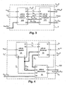
- FIG. 1 there is shown a block diagram of a vehicle equipped with a powertrain (GMP).
- the powertrain GMP consists of a heat engine (ICE ) 4 controlled in torque and an infinitely variable transmission (IVT) 5.
- This transmission consists of a kinematic chain 13 having four channels of mechanical power exchange and of an electric variator 21.
- the electric variator 21 itself consists of two electrical machines M e1 , 11 and M e2 , 12 controlled in pairs and electrically linked by a buffer element of energy 10.
- energy storage 10 of the embodiment describes either a capacitor, the control method is also applicable in the case of infinitely variable transmission with a different technology energy storage such as a battery or supercapacitor.
- the heat engine 4 is controlled in torque by a controller 3 and the electrical machines 11 and 12 are respectively controlled by a controller 19 and by a controller 20.
- the kinematic chain 13 of the transmission IVT 5 thus comprises that couplers are known as clutches and brakes which are controlled by a transmission mode controller which is not described or represented in the present application but which is defined in the above-mentioned previous patent applications of the applicant.
- the heat engine provides a positive torque to the transmission (pull).
- the mechanical objectives pursued by the process of the invention is the regulation of the engine speed and the torque supplied to the wheels.
- the energy objective pursued by the method of the invention is the regulation of the capacitor voltage.
- X1 and X2 W ⁇ PDW
- control signal emitted by a line 7 is a torque command signal T ice # of the heat engine.
- control signal emitted by lines 8 and 9 is a pair of torque control signals T e1 # and T e2 # respectively transmitted to suitable inputs of the controllers 19 and 20 of the electrical machines M e1 11 and M e2 12.
- the method of the invention is based on the three-way multivariable control structure presented in the publication FR 2834249 .
- the object of the present invention is to construct the intermediate control layer (COS) in the "draw" mode in which the heat engine is controlled by the two upper layers, without being decoupled from the infinitely variable transmission.
- COS intermediate control layer
- the supervisor or controller who performs the optimization of the operating point of the heat engine provides the input of the third layer controller a speed reference of the engine.
- the supervisor or controller also provides a torque setpoint to the wheels.
- There is also a voltage setpoint of the capacitor which is most often used as an energy buffer element for the electric drive. From these three setpoints and available measurements describing the vehicle environment, such as the speed of the vehicle or the slope in which it is engaged, the controller generates the torque setpoints for the three main actuators of the GMP, namely the two electric machines (Me1 and Me2) and the heat engine.
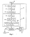
- step S0 After a command start operation in a step S0 in which the control device of the invention is configured and initialized, and subsequently only initialized except during maintenance operations, the control switches to a step S1 during which a mechanical control signal uo, as well as the torque setpoint of the heat engine T ice # are calculated on the basis of a measurement vector Z.
- the measurement vector Z is composed of the measurement of the torques provided by the two electrical machines Te1, Te2, of their regimes ⁇ e1, ⁇ e2 as well as of the voltage Ucapa at the terminals of the storage element energy.
- Step S1 is characterized by the fact that only the objective of mechanical regulation is taken into account and the control which results from the heat engine is then directly available and can be applied to the actuators of the engine.
- the method of the invention consists in producing an intermediate control signal u 0 and a signal representative of the torque set T ice # of the heat engine.
- the method of the invention consists in taking into account the torque estimates of the electrical machines of the variator, as well as the previous value of the mechanical control signal estimated at the preceding step of calculation as well as a energy control signal u w .
- the method of the invention consists in producing an energy control signal u w , a correction of the mechanical control signal u 0 (n), torque estimates of the electrical machines of the variator ⁇ T e1 and ⁇ T e2 as well as setpoint signals of the pairs of electrical machines T e1 # and T e2 # that will actually be applied to the controllers 14 and 15.
- the method of the invention consists in taking into account , in addition to the measurement signals of the quantities measured in the Z vector ( Figure 1 ) sensors of the system, the intermediate control signal u 0 , calculated during the preceding mechanical control step.
- an end-of-loop test is carried out to determine if the control of the invention ends when a decision of end of training mode in "draw" mode has been taken.
- the control unit 34 comprises a processor or part of processor assigned to the execution at each computation step of a new update of the vector (v1, v2) described in step S12 which comprises two calculation units respectively of the first intermediate control signal v1 and the second intermediate control signal v2.
- the determination unit 36 of the estimate ⁇ Xf has the role of constructing the estimation signal ⁇ Xf containing the main variables describing the state of the system.
- FIG. 5 A particular embodiment is shown for making a circuit for carrying out the calculation of the mechanical control signal u 0 and the torque setpoint of the engine T ice #.
- the circuit 110 produces in the manner that has been recalled above two intermediate control signals u1 and u2 which are respectively supplied to the input of a discrete integrator circuit 111 to produce the mechanical control signal u 0 and to a circuit 112 of saturation of the engine torque dependent on the engine speed.
- the output signal of the circuit 112 is then supplied to the input of a circuit 113 which applies a predetermined discrete delay and produces the engine torque setpoint T ice # .
- FIG. figure 6 there is shown a particular embodiment of an energy control unit 101 as shown in FIG. figure 3 .
- the method of the invention comprises a step of calculating an energy control signal u w that executes in three successive steps.
- an energy calculation unit 120 produces a first estimate of the energy control signal u w on the basis of the voltage measured across the Ucapa energy buffer element.
- a second step 121 we estimate the pairs T e1 and T e2 of the electrical machines and their disturbances.
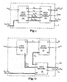
- FIG. 7 illustrating the retro mode, there is shown a block diagram of a vehicle equipped with a powertrain (GMP).
- the powertrain GMP consists of a heat engine (ICE) 4 controlled in torque and an infinitely variable transmission (IVT) 5.
- This transmission consists of a kinematic chain 13 having four channels of mechanical power exchange and of an electric variator 21.
- the electric variator 21 itself consists of two electrical machines M e1 , 11 and M e2 , 12 controlled in pairs and electrically linked by a buffer element of energy 10.
- energy storage 10 of the embodiment describes either a capacitor, the control method is also applicable in the case of infinitely variable transmission with a different technology energy storage such as a battery or supercapacitor.
- the heat engine 4 is controlled in torque by a controller 3 and the electrical machines 11 and 12 are respectively controlled by a controller 19 and by a controller 20.
- the kinematic chain 13 of the transmission IVT 5 thus comprises that couplers are known as clutches and brakes that are controlled by a transmission mode controller.
- the mode of operation of the GMP powertrain concerned by the figure 7 is a training mode called "retro" in which the engine provides a transmission-resistant torque.
- the only mechanical objective pursued by the method of the invention is the regulation of the engine speed.
- the energy objective pursued by the method of the invention is the regulation of the capacitor voltage.
- X1 and X2 W ⁇ PDW
- control device 2 In response, and by applying the method of the invention, the control device 2 returns a control signal transmitted by lines 8 and 9 to the controllers of the electric drive 21 which makes it possible to reach the control objective on the engine speed whatever the torque at the To wheel.
- control signal transmitted by the lines 8 and 9 is a pair of torque T control signals e1 # and T e2 # respectively transmitted to suitable inputs of controllers 19 and 20 of M electrical machines e1 11 and M e2 12.
- the method of the invention is based on the three-way multivariable control structure presented in the publication FR2834249 .
- the object of the present invention is to build the intermediate control layer (COS) in the "retro" mode in which the heat engine is not controlled by the two upper layers.
- COS intermediate control layer
- the supervisor or OPF controller that performs the optimization of the operating point of the engine provides the input of the third layer controller COS a speed reference of the engine. There is also a voltage setpoint of the capacitor which is most often used as an energy buffer element for the electric drive. From these two instructions and available measurements describing the environment of the vehicle, such as the speed of the vehicle or the slope in which it is engaged, the COS controller generates the torque setpoints for the two main actuators of the GMP, namely the two electrical machines (Me1 and Me2) in the "retro" mode of the invention.
- step S0 After a command start operation in a step S0 in which the control device of the invention is configured and then initialized, and subsequently only initialized except during maintenance operations, the control goes to a step S1 at during which a mechanical control signal u0 is calculated on the basis of a measurement vector Z.
- the measurement vector Z is composed of the measurement of the torques provided by the two electrical machines Te1, Te2, of their regimes ⁇ e1, ⁇ e2 as well as of the voltage Ucapa at the terminals of the storage element energy.
- Step S1 is characterized by the fact that only the objective of mechanical regulation is taken into account.
- the method of the invention consists in producing an intermediate control signal u 0 .
- the method of the invention consists in taking into account the torque estimates of the electrical machines of the variator, the previous value of the mechanical control signal estimated at the preceding step of calculation and a signal of energy control u w.
- the method of the invention consists in producing an energy control signal u w , a correction of the mechanical control signal u 0 (n), torque estimates of the electrical machines of the variator ⁇ T e1 and ⁇ T e2 as well as set signals of the pairs of electrical machines T e1 # and T e2 # which will actually be applied to the controllers 14 and 15.
- the method of the invention consists in taking into account, in addition to the measurement signals of the quantities measured in the vector Z ( Figure 7 ) sensors of the system, the intermediate control signal u 0 , calculated during the preceding mechanical control step.
- an end-of-loop test is carried out to determine whether the control of the invention ends when a decision of end of training mode in "retro" mode has been taken.
- the control unit 34 has an intermediate control signal output port S1 v1.
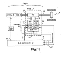
- FIG. figure 11 A particular embodiment of the decoupling unit 35 has been shown in FIG. figure 11 which will be described later.
- the determination unit 36 of the estimate ⁇ Xf has the role of constructing the estimation signal ⁇ Xf containing the main variables describing the state of the system.
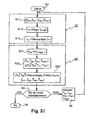
- FIG 11 there is shown a particular embodiment of a circuit for performing the calculation of the mechanical control signal u 0 .
- the circuit 110 produces in the manner that has been recalled above the intermediate control signal u1 which is supplied to the input of a discrete integrator circuit 111 to produce the mechanical control signal u 0 .
- FIG. figure 12 there is shown a particular embodiment of an energy control unit 101 as shown in FIG. figure 9 .
- the method of the invention comprises a step of calculating an energy control signal u w that executes in three successive steps.
- an energy calculation unit 120 In a first step, an energy calculation unit 120 generates a first estimate of u w energy control signal on the basis of the voltage measured across the U capa energy buffer element.
- a second step 121 we estimate the pairs T e1 and T e2 of the electrical machines and their disturbances.
- FIG. 13 relating to the torque ramp mode, there is shown a block diagram of a vehicle equipped with a powertrain (GMP).
- the powertrain GMP consists of a heat engine (ICE) 4 controlled in torque and an infinitely variable transmission (IVT) 5.
- This transmission consists of a kinematic chain 13 having four channels of mechanical power exchange and of an electric variator 21.
- the electric variator 21 itself consists of two electrical machines M e1 , 11 and M e2 , 12 controlled in pairs and electrically linked by a buffer element of energy 10.
- energy storage 10 of the embodiment describes either a capacitor, the control method is also applicable in the case of infinitely variable transmission with a different technology energy storage such as a battery or supercapacitor.
- the heat engine 4 is controlled in torque by a controller 3 and the electrical machines 11 and 12 are respectively controlled by a controller 19 and by a controller 20.
- the kinematic chain 13 of the transmission IVT 5 thus comprises that couplers are known as clutches and brakes which are controlled by a transmission mode controller which is not described or represented in the present application but which is defined in the above-mentioned previous patent applications of the applicant.
- the mode of operation of the GMP powertrain concerned by the figure 13 is a mode called "torque ramping" mode in which the engine provides an idle torque to the transmission.
- torque ramping the only mechanical objective pursued by the method of the invention is the regulation of the torque to the wheels.
- the energy objective pursued by the method of the invention is the regulation of the capacitor voltage.
- control device 2 In response, and by applying the method of the invention, the control device 2 returns control signals transmitted by lines 8 and 9 to the controllers of the electric drive 21 which makes it possible to reach the objective of regulating torque. to the wheel To.
- control signal emitted by lines 8 and 9 is a pair of torque control signals T e1 # and T e2 # respectively transmitted to suitable inputs of the controllers 19 and 20 of the electrical machines M e1 11 and M e2 12.
- the method of the invention is based on the three-way multivariable control structure presented in the publication FR2834249 .
- the object of the present invention is to build the intermediate control layer (COS) in the "torque ramping" mode in which the heat engine is not controlled by the two upper layers, but works in idle mode without to be decoupled from infinitely variable transmission. In this situation, the vehicle moves at a low speed and the braking system can be activated. The mechanical target is then a torque at the wheel which reduces the speed of the vehicle.
- COS intermediate control layer
- the supervisor or controller supplies the input of the third layer controller with a torque setpoint to the wheels.
- a voltage setpoint of the capacitor which is most often used as an energy buffer element for the electric drive. From these two setpoints and available measurements describing the vehicle environment, such as the speed of the vehicle or the slope in which it is engaged, the controller generates the torque setpoints for the two main GMP actuators, namely the two electrical machines (Me1 and Me2) in the "torque ramping" mode of the invention.
- step S0 After a command start operation in a step S0 in which the control device of the invention is configured and then initialized, and subsequently only initialized except during maintenance operations, the control goes to a step S1 at during which a mechanical control signal u0 is calculated on the basis of a measurement vector Z.
- the measurement vector Z is composed of the measurement of the torques provided by the two electrical machines Te1, Te2, of their regimes ⁇ e1, ⁇ e2 as well as of the voltage Ucapa at the terminals of the storage element energy.
- Step S1 is characterized by the fact that only the objective of mechanical regulation is taken into account and no control derives for the heat engine which is then indirectly controlled by an idle controller.
- the method of the invention consists in producing an intermediate control signal u 0 .
- the method of the invention consists in taking into account the torque estimates of the electrical machines of the variator, as well as the previous value of the mechanical control signal estimated at the preceding step of calculation as well as a energy control signal u w .
- the method of the invention consists in producing an energy control signal u w , a correction of the mechanical control signal u 0 (n), torque estimates of the electrical machines of the variator ⁇ T e1 and ⁇ T e2 as well as setpoint signals of the pairs of electrical machines T e1 # and T e2 # that will actually be applied to the controllers 14 and 15.
- the method of the invention consists in taking into account , in addition to the measurement signals of the quantities measured in the vector Z ( Figure 13 ) sensors of the system, the intermediate control signal u 0 , calculated during the preceding mechanical control step.
- an end-of-loop test is carried out to determine whether the control of the invention ends when a decision of end of training mode in "torque ramping" mode has been taken.
- the control unit 34 has an intermediate control signal output port S2 v2.
- the decoupling unit 35 has an output port S1 which provides a mechanical control signal u0.
- FIG. figure 17 A particular embodiment of the decoupling unit 35 has been shown in FIG. figure 17 which will be described later.
- the determination unit 36 of the estimate ⁇ Xf has the role of constructing the estimation signal ⁇ Xf containing the main variables describing the state of the system.
- FIG. 17 there is shown a particular embodiment of a circuit for performing the calculation of the mechanical control signal u0.
- the circuit 110 produces in the manner that has been recalled above the intermediate control signal u1 which is supplied to the input of a discrete integrator circuit 111 to produce the mechanical control signal u0.
- FIG. 18 there is shown a particular embodiment of an energy control unit 101 as shown in FIG. figure 3 .
- the method of the invention comprises a step of calculating an energy control signal u w that executes in three successive steps.
- an energy calculation unit 120 produces a first estimate of the energy control signal u w on the basis of the voltage measured across the Ucapa energy buffer element.
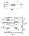
- FIG. 19 relating to speed ramping mode, there is shown a block diagram of a vehicle equipped with a powertrain (GMP).
- the powertrain GMP consists of a heat engine (ICE) 4 controlled in torque and an infinitely variable transmission (IVT) 5.
- This transmission consists of a kinematic chain 13 having four channels of mechanical power exchange and of an electric variator 21.
- the electric variator 21 itself consists of two electrical machines M e1 , 11 and M e2 , 12 controlled in pairs and electrically linked by a buffer element of energy 10.
- energy storage 10 of the embodiment describes either a capacitor, the control method is also applicable in the case of infinitely variable transmission with a different technology energy storage such as a battery or supercapacitor.
- the heat engine 4 is controlled in torque by a controller 3 and the electrical machines 11 and 12 are respectively controlled by a controller 19 and by a controller 20.
- the kinematic chain 13 of the transmission IVT 5 thus comprises that couplers are known as clutches and brakes which are controlled by a transmission mode controller which is not described or represented in the present application but which is defined in the above-mentioned previous patent applications of the applicant.
- the mode of operation of the GMP powertrain concerned by the figure 19 is a drive mode called "speed ramping" during which the engine provides idle torque to the transmission.
- speed ramping the only mechanical objective pursued by the method of the invention is the regulation of the wheels speed.
- the energy objective pursued by the method of the invention is the regulation of the capacitor voltage.
- control device 2 In response, and by applying the method of the invention, the control device 2 returns control signals transmitted by lines 8 and 9 to the controllers of the electric drive 21 which makes it possible to reach the objective of regulating the speed wheels.
- control signal transmitted by the lines 8 and 9 is a pair of torque T control signals e1 # and T e2 # respectively transmitted to suitable inputs of controllers 19 and 20 of M electrical machines e1 11 and M e2 12.
- the method of the invention is based on the three-way multivariable control structure presented in the publication FR2834249 .
- An object of the present invention is to build the intermediate control layer (COS) in the "speed ramping" mode in which the heat engine is not controlled by the two upper layers, but works in idle mode without being decoupled from infinitely variable transmission, even in "neutral-in-engagement".
- COS intermediate control layer
- the supervisor or controller IVC supplies the input of the third layer controller COS with a wheel speed reference.
- a voltage setpoint of capacitor that most often serves as an energy buffer for the electric drive.
- step S0 After a command start operation in a step S0 in which the control device of the invention is configured and then initialized, and subsequently only initialized except during maintenance operations, the control goes to a step S1 at during which a mechanical control signal u0 is calculated on the basis of a measurement vector Z.
- the measurement vector Z is composed of the measurement of the torques provided by the two electrical machines T e1 , T e2 , their regimes ⁇ e1 , ⁇ e2 as well as the voltage Ucapa at the terminals of the energy storage element.
- Step S1 is characterized by the fact that only the objective of mechanical regulation is taken into account and no control derives for the heat engine which is then indirectly controlled by an idle controller.
- the method of the invention consists in producing an intermediate control signal u 0 .
- the method of the invention consists in taking into account the estimates of the torques of the machines. of the drive, the previous value of the signal mechanical control estimated at the previous step of calculation as well as an energy control signal u w .
- the method of the invention consists in producing an energy control signal u w , a correction of the mechanical control signal u 0 (n), torque estimates of the electrical machines of the variator ⁇ T e1 and ⁇ T e2 as well as setpoint signals of the pairs of electrical machines T e1 # and T e2 # that will actually be applied to the controllers 14 and 15.
- the method of the invention consists in taking into account , in addition to the measurement signals of the quantities measured in the vector Z ( Figure 19 ) sensors of the system, the intermediate control signal u 0 , calculated during the preceding mechanical control step.
- an end-of-loop test is carried out to determine whether the control of the invention ends when a decision of end of training mode in "speed ramping" mode has been taken.
- the control unit 34 has an intermediate control signal output port S1 v1.
- the decoupling unit 35 has an output port S1 which provides a mechanical control signal u0;
- FIG. figure 23 A particular embodiment of the decoupling unit 35 has been shown in FIG. figure 23 which will be described later.
- the determination unit 36 of the estimate ⁇ Xf has the role of constructing the estimation signal ⁇ Xf containing the main variables describing the state of the system.
- FIG 23 there is shown a particular embodiment of a circuit for performing the calculation of the mechanical control signal u0.
- the circuit 110 produces in the manner that has been recalled above an intermediate control signal u1 which is supplied to the input of a discrete integrator circuit 111 to produce the mechanical control signal u0.
- FIG. figure 24 there is shown a particular embodiment of an energy control unit 101 as shown in FIG. figure 21 .
- the method of the invention comprises a step of calculating an energy control signal u w that executes in three successive steps.
- an energy calculation unit 120 produces a first estimate of the control signal energy u w based on the voltage measured across the Ucapa energy buffer element.
- a second step 121 we estimate the pairs T e1 and T e2 of the electrical machines and their disturbances.
Claims (24)
- Verfahren zur Steuerung einer Motorantriebseinheit eines Fahrzeugs, umfassend einen Wärmekraftmotor, der direkt an die Räder des Fahrzeugs gekoppelt ist, und ein stufenlos einstellbares Getriebe mit elektrischem Variator, die zwei elektrische Maschinen einschließt, gemäß denen das Fahrzeug von der Motorantriebseinheit angetrieben, von dieser gebremst, von dieser abgeschaltet oder im Stillstand gehalten werden kann, dadurch gekennzeichnet, dass es, in einer spezifischen Antriebsart des Fahrzeugs durch die Motorantriebseinheit, darin besteht- in einem ersten Schritt das Drehmoment des Wärmekraftmotors (Tice#) zu berechnen, und darin, gleichzeitig das Radmoment und die Drehzahl des Wärmekraftmotors zu regulieren, ein mechanisches Steuerungssignal (u0) zu erzeugen, das die ermittelten Drehmoment-Drehzahl-Kennlinien repräsentiert; dann- in einem zweiten Schritt die Drehmomente (Te1#; Te2#) der ersten und zweiten elektrischen Maschinen auf der Basis des mechanischen Steuerungssignals zu berechnen, und ein energetisches Steuerungssignal zu erzeugen, das das Energieniveau reguliert;indem ausschließlich eine Messung des Ladungsniveaus des Elektroenergie-Pufferelements (Ucapa) und Drehzahlmessungen (ωe1 ωe2) und (Te1, Te2) des Drehmoments, das von den elektrischen Maschinen (Me1 11, Me2 12) geliefert wird, genutzt werden;
und dadurch dass es die spezifische Antriebsart ermöglicht, die Leerlaufregulierung des Wärmekraftmotors zu gewährleisten und dabei das Drehmoment (To) zu kontrollieren, das von der Motorantriebseinheit geliefert wird. - Verfahren nach Anspruch 1, dadurch gekennzeichnet, dass der erste Schritt des Verfahrens die folgenden Schritte umfasst:- Bestimmen des Radmoments (To), der Drehzahlen der elektrischen Maschinen des Variators (21) und der Drehzahl des Wärmekraftmotors (ωice)- Erhalten der Zwischenwerte (v1, v2) durch Regulierung des Radmoments und der Wärmekraftmotordrehzahl, die in Abhängigkeit von Sollwerten bestimmt werden, und- Entkoppeln der Zwischenwerte (v1, v2) in ein mechanisches Steuerungssignal (u0) und ein Steuerungssignal (Tice#) des Wärmekraftmotors (4).
- Verfahren zur Steuerung nach Anspruch 1 oder 2, dadurch gekennzeichnet, dass der zweite Schritt des Verfahrens die folgenden Schritte umfasst:- Berechnen eines energetischen Steuerungssignals (uw) auf der Basis der Messung der Spannung des Energiepufferelements des elektrischen Variators (21);- Bestimmen der Drehmomente (^Te1; ^Te2) der ersten und zweiten elektrischen Maschinen des Variators (21) und ihrer Korrekturfaktoren (^Tde1, ^Tde2) auf der Basis der Messung der Drehmomente und der Steuerungssignale (Te1#, Te2#) der elektrischen Maschinen während eines vorhergehenden Zeitraums;- energetisches Entkoppeln des energetischen Steuerungssignals und des mechanischen Steuerungssignals (u0), die während des ersten Schritts auf der Basis der Drehzahlen, die bestimmt wurden, und der Korrekturfaktoren der beiden elektrischen Maschinen des Variators (21) erzeugt wurden.
- Verfahren nach Anspruch 3, dadurch gekennzeichnet, dass im ersten Schritt der Schritt des Bestimmens das energetische Steuerungssignal (uw) nutzt, das während des zweiten Schritts in einem vorhergehenden Zeitraum berechnet wurde, und der Schritt des Entkoppelns der Zwischensignale die Werte nutzt, die bestimmt wurden:- der Drehzahlen (ωe1, ωe2) der elektrischen Maschinen (Me1, 11, Me2, 12),- der Drehzahl (ωice) des Wärmekraftmotors (4),- des Drehmoments (Tice) das auf die Kurbelwelle des Wärmekraftmotors (4) angewendet wird,- des mechanischen Steuerungssignals (uo(n)), das während des Schritts der energetischen Entkopplung im zweiten Schritt in einem vorhergehenden Zeitraum korrigiert wurde,- der Korrekturfaktoren der Drehmomente, die auf die Rotoren der elektrischen Maschinen angewendet werden,- der Korrekturfaktoren der Drehmomente, die auf die Kurbelwelle und auf die Räder angewendet werden.
- Verfahren zur Steuerung nach einem der Ansprüche 1 bis 4, dadurch gekennzeichnet, dass es, in einer spezifischen Antriebsart des Fahrzeugs durch die Motorantriebseinheit, darin besteht- in einem ersten Schritt die Drehzahl des Wärmekraftmotors zu regulieren, ein mechanisches Steuerungssignal (u0) zu erzeugen, das die ermittelten Drehmoment-Drehzahl-Kennlinien repräsentiert; dann- in einem zweiten Schritt die Drehmomente (Te1#; Te2#) der ersten und zweiten elektrischen Maschinen auf der Basis des mechanischen Steuerungssignals zu berechnen, und ein energetisches Steuerungssignal zu erzeugen, das das Energieniveau reguliert;indem ausschließlich eine Messung des Ladungsniveaus des Elektroenergie-Pufferelements (Ucapa) und Drehzahlmessungen (ωe1, ωe2) und (Te1, Te2) des Drehmoments, das von den elektrischen Maschinen (Me1 11, Me2 12) geliefert wird, genutzt werden.
- Verfahren nach Anspruch 5, dadurch gekennzeichnet, dass der erste Schritt des Verfahrens die folgenden Schritte umfasst:- Bestimmen der Drehzahlen der elektrischen Maschinen des Variators (21) und der Drehzahl des Wärmekraftmotors (ωice),- Erhalten eines Zwischenwerts (v1) durch Regulierung der Wärmekraftmotordrehzahl, die in Abhängigkeit von einem Sollwert bestimmt wurde, und- Entkoppeln des Zwischenwerts (v1) in ein mechanisches Steuerungssignal (u0).
- Verfahren zur Steuerung nach Anspruch 5 oder 6, dadurch gekennzeichnet, dass der zweite Schritt des Verfahrens die folgenden Schritte umfasst:- Berechnen eines energetischen Steuerungssignals (uw) auf der Basis der Messung der Spannung des Energiepufferelements des elektrischen Variators (21);- Bestimmen der Drehmomente (^Te1; ^Te2) der ersten und zweiten elektrischen Maschinen des Variators (21) und ihrer Korrekturfaktoren (^Tde1, ^Tde2) auf der Basis der Messung der Drehmomente und der Steuerungssignale (Te1#, Te2#) der elektrischen Maschinen während eines vorhergehenden Zeitraums;- energetisches Entkoppeln des energetischen Steuerungssignals (uw) und des mechanischen Steuerungssignals (u0), die während des ersten Schritts auf der Basis der bestimmten Drehzahlen und der Korrekturfaktoren der beiden elektrischen Maschinen des Variators (21) erzeugt wurden.
- Verfahren nach Anspruch 7, dadurch gekennzeichnet, dass im ersten Schritt der Schritt des Bestimmens das energetische Steuerungssignal (uw) nutzt, das während des zweiten Schritts in einem vorhergehenden Zeitraum berechnet wurde, und der Schritt des Entkoppelns der Zwischensignale die Werte nutzt, die bestimmt wurden, der:- Drehzahlen (ωe1, ωe2) der elektrischen Maschinen (Me1, 11; Me2, 12),- des Drehmoments (Tice) das auf die Kurbelwelle des Wärmekraftmotors (4) angewendet wird,- des mechanischen Steuerungssignals (uo(n)), das während des Schritts der energetischen Entkopplung im zweiten Schritt in einem vorhergehenden Zeitraum korrigiert wurde,- der Korrekturfaktoren der Drehmomente, die auf die Kurbelwelle und auf die Räder angewendet werden.
- Verfahren zur Steuerung nach einem der vorhergehenden Ansprüche, dadurch gekennzeichnet, dass es, in einer spezifischen Antriebsart des Fahrzeugs durch die Motorantriebseinheit, darin besteht- in einem ersten Schritt das Radmoment zu regulieren, ein mechanisches Steuerungssignal (u0) zu erzeugen, das die ermittelten Drehmoment-Drehzahl-Kennlinien repräsentiert; dann- in einem zweiten Schritt die Drehmomente (Te1#; Te2#) der ersten und zweiten elektrischen Maschinen auf der Basis des mechanischen Steuerungssignals (u0) zu berechnen, und ein energetisches Steuerungssignal (uw) zu erzeugen, das das Energieniveau reguliert;indem ausschließlich eine Messung des Ladungsniveaus des Elektroenergie-Pufferelements (Ucapa) und Drehzahlmessungen (ωe1, ωe2) und (Te1, Te2) des Drehmoments, das von den elektrischen Maschinen (Me1, 11, Me2, 12) geliefert wird, genutzt werden.
- Verfahren nach Anspruch 9, dadurch gekennzeichnet, dass es die spezifische Antriebsart ermöglicht, das Drehmoment zurückzunehmen, das von der Motorantriebseinheit geliefert wird, indem die Energie, die von dem Wärmekraftmotor geliefert wird, abgeleitet wird.
- Verfahren nach Anspruch 9 oder 10, dadurch gekennzeichnet, dass der erste Schritt des Verfahrens die folgenden Schritte umfasst:- Bestimmen des Radmoments (To) und der Drehzahlen der elektrischen Maschinen des Variators (21),- Erhalten eines Zwischenwerts (v2) durch Regulierung des Radmoments, das in Abhängigkeit von einem Sollwert bestimmt wurde, und- Entkoppeln des Zwischenwerts (v2) in ein mechanisches Steuerungssignal (u0).
- Verfahren zur Steuerung nach Anspruch 9 oder 10, dadurch gekennzeichnet, dass der zweite Schritt des Verfahrens die folgenden Schritte umfasst:- Berechnen eines energetischen Steuerungssignals (uw) auf der Basis der Messung der Spannung des Energiepufferelements des elektrischen Variators (21);- Bestimmen der Drehmomente (^Te1; ^Te2) der ersten und zweiten elektrischen Maschinen des Variators (21) und ihrer Korrekturfaktoren (^Tde1, ^Tde2) auf der Basis der Messung der Drehmomente und der Steuerungssignale (Te1#, Te2#) der elektrischen Maschinen während eines vorhergehenden Zeitraums;- energetisches Entkoppeln des energetischen Steuerungssignals (uw) und des mechanischen Steuerungssignals (u0), die während des ersten Schritts auf der Basis der bestimmten Drehzahlen und der Korrekturfaktoren der beiden elektrischen Maschinen des Variators (21) erzeugt wurden.
- Verfahren nach Anspruch 12, dadurch gekennzeichnet, dass im ersten Schritt der Schritt des Bestimmens das energetische Steuerungssignal (uw) nutzt, das während des zweiten Schritts in einem vorhergehenden Zeitraum berechnet wurde, und der Schritt des Entkoppelns der Zwischensignale die Werte nutzt, die bestimmt wurden:- der Drehzahlen (ωe1, ωe2) der elektrischen Maschinen (Me1, 11; Me2, 12),- des Drehmoments (Tice) das auf die Kurbelwelle des Wärmekraftmotors (4) angewendet wird,- des mechanischen Steuerungssignals (uo(n)), das während des Schritts der energetischen Entkopplung im zweiten Schritt in einem vorhergehenden Zeitraum korrigiert wurde,- der Korrekturfaktoren der Drehmomente, die auf die Rotoren der elektrischen Maschinen angewendet werden,- der Korrekturfaktoren der Drehmomente, die auf die Kurbelwelle und auf die Räder angewendet werden.
- Verfahren zur Steuerung nach einem der Ansprüche 1 bis 13, dadurch gekennzeichnet, dass es, in einer spezifischen Antriebsart des Fahrzeugs durch die Motorantriebseinheit, darin besteht- in einem ersten Schritt die Raddrehzahl zu regulieren, ein mechanisches Steuerungssignal (u0) zu erzeugen, das die ermittelten Drehmoment-Drehzahl-Kennlinien repräsentiert; dann- in einem zweiten Schritt die Drehmomente (Te1#; Te2#) der ersten und zweiten elektrischen Maschinen auf der Basis des mechanischen Steuerungssignals (u0) zu berechnen, und ein energetisches Steuerungssignal (uw) zu erzeugen, das das Energieniveau reguliert;indem ausschließlich eine Messung des Ladungsniveaus des Elektroenergie-Pufferelements (Ucapa) und Drehzahlmessungen (ωe1, ωe2) und (Te1, Te2) des Drehmoments, das von den elektrischen Maschinen (Me1, 11, Me2, 12) geliefert wird, genutzt werden.
- Verfahren nach Anspruch 14, dadurch gekennzeichnet, dass es die spezifische Antriebsart ermöglicht, die Geschwindigkeit des Fahrzeugs zurückzunehmen, indem die Energie, die von dem Wärmekraftmotor geliefert wird, abgeleitet wird.
- Verfahren nach Anspruch 14 oder 15, dadurch gekennzeichnet, dass der erste Schritt des Verfahrens die folgenden Schritte umfasst:- Bestimmen der Raddrehzahl und der Drehzahlen der elektrischen Maschinen des Variators (21),- Erhalten eines Zwischenwerts (v1) durch Regulierung der Raddrehzahl (ωwh), die in Abhängigkeit von einem Sollwert bestimmt wurde, und- Entkoppeln des Zwischenwerts (v1) in ein mechanisches Steuerungssignal (u0).
- Verfahren zur Steuerung nach Anspruch 14 oder 15, dadurch gekennzeichnet, dass der zweite Schritt des Verfahrens die folgenden Schritte umfasst:- Berechnen eines energetischen Steuerungssignals (uw) auf der Basis der Messung der Spannung des Energiepufferelements des elektrischen Variators (21);- Bestimmen der Drehmomente (^Te1; ^Te2) der ersten und zweiten elektrischen Maschinen des Variators (21) und ihrer Korrekturfaktoren (^Tde1, ^Tde2) auf der Basis der Messung der Drehmomente und der Steuerungssignale (Te1#, Te2#) der elektrischen Maschinen während eines vorhergehenden Zeitraums;- energetisches Entkoppeln des energetischen Steuerungssignals (uw) und des mechanischen Steuerungssignals (u0), die während des ersten Schritts auf der Basis der bestimmten Drehzahlen und der Korrekturfaktoren der beiden elektrischen Maschinen des Variators (21) erzeugt wurden.
- Verfahren nach Anspruch 17, dadurch gekennzeichnet, dass im ersten Schritt der Schritt des Bestimmens das energetische Steuerungssignal (uw) nutzt, das während des zweiten Schritts in einem vorhergehenden Zeitraum berechnet wurde, und der Schritt des Entkoppelns der Zwischensignale die Werte nutzt, die bestimmt wurden:- der Drehzahlen (ωe1, ωe2) der elektrischen Maschinen (Me1, 11; Me2, 12),- des Drehmoments (Tice) das auf die Kurbelwelle des Wärmekraftmotors (4) angewendet wird,- des mechanischen Steuerungssignals (uo(n)), das während des Schritts der energetischen Entkopplung im zweiten Schritt in einem vorhergehenden Zeitraum korrigiert wurde,- der Korrekturfaktoren der Drehmomente, die auf die Rotoren der elektrischen Maschinen angewendet werden,- der Korrekturfaktoren der Drehmomente, die auf die Räder angewendet werden.
- Vorrichtung zur Steuerung von Stellgliedern einer Motorantriebseinheit, um das Verfahren nach einem der Ansprüche 1 bis 8 durchzuführen, umfassend:- ein erstes Kontrollmittel (20), um den Wunsch des Fahrers zu interpretieren,- ein zweites Kontrollmittel (22), um einen optimalen Arbeitspunkt des Wärmekraftmotors zu bestimmen, und- ein drittes Kontrollmittel (25), um Steuerungssignale der Stellglieder der Motorantriebseinheit zu erzeugen,dadurch gekennzeichnet, dass das dritte Kontrollmittel (25) umfasst:- eine mechanische Kontrolleinheit (100), um ein mechanisches Steuerungssignal (u0) zu erzeugen, das die Drehmoment-Drehzahl-Kennlinien repräsentiert;- eine energetische Kontrolleinheit (101), die mit der mechanischen Kontrolleinheit verbunden ist, um Sollwerte der Drehmomente der elektrischen Maschinen des elektrischen Variators des stufenlos einstellbaren Getriebes zu erzeugen.
- Vorrichtung zur Steuerung nach Anspruch 19, dadurch gekennzeichnet, dass das mechanische Signal (u0) die ermittelten Drehmoment-Drehzahl-Kennlinien repräsentiert.
- Vorrichtung zur Steuerung nach Anspruch 19 oder 20, dadurch gekennzeichnet, dass die Entkopplungseinheit (35) der mechanischen Kontrolleinheit (100) umfasst:- ein nicht lineares Entkopplungsmodul (110), das mindestens eines der folgenden Signale empfängt:- die ermittelten Werte (^Xf) des Zustands der Motorantriebseinheit,- die Zwischenwerte der Steuerungssignale (v1, v2), die durch Regulierung auf der Basis eines Sollpunkts des Zustands der Motorantriebseinheit (To*, ωice*) und der Ermittlung dieser Sollwerte erhalten wurden;- einen Wert, der aus einem mechanischen Steuerungssignal (uo(n)) während eines vorhergehenden Schritts während der Feststellung eines energetischen Steuerungssignals berechnet wurde;
wobei das Modul (110) ein erstes Zwischensignal (u1), das von der mechanischen Steuerung abgeleitet ist, und ein zweites Zwischensignal (u2) erzeugt;- ein Modul (111), das auf das erste abgeleitete Signal (u1) eine diskrete Integration anwendet, um einen Wert des mechanischen Steuerungssignals (u0) zu erzeugen;- ein Modul (112), das auf den zweiten Ausgang des Moduls (110) eine Sättigung in Abhängigkeit von der ermittelten Drehzahl des Wärmekraftmotors (^ωice) anwendet;- ein Kreislauf (113), der eine Verzögerung auf das Ausgangssignal des Sättigungskreislaufs (112) anwendet, um ein Steuerungssignal des Drehmoments (Tice#) des Wärmekraftmotors zu erzeugen. - Vorrichtung zur Steuerung nach Anspruch 19 oder 20, dadurch gekennzeichnet, dass die Entkopplungseinheit (35) der mechanischen Kontrolleinheit (100) umfasst:- ein nicht lineares Entkopplungsmodul (110), das mindestens eines der folgenden Signale empfängt:- die ermittelten Zustandswerte (^Xf) der Motorantriebseinheit,- die Zwischenwerte eines Steuerungssignals (v1), das durch Regulierung auf der Basis eines Sollpunkts des Zustands des Wärmekraftmotors (ωice*) und der Ermittlung des Sollwerts erhalten wurde;- einen Wert, der aus einem mechanischen Steuerungssignal (uo(n)) während eines vorhergehenden Schritts während der Ermittlung eines energetischen Steuerungssignals berechnet wurde;
wobei das Modul (110) ein Zwischensignal (u1) erzeugt, das von der mechanischen Steuerung abgeleitet ist;- ein Modul (111), das auf das abgeleitete Signal (u1) eine diskrete Integration anwendet, um einen Wert des mechanischen Steuerungssignals (u0) zu erzeugen. - Vorrichtung zur Steuerung nach Anspruch 19 oder 20, dadurch gekennzeichnet, dass die Entkopplungseinheit (35) der mechanischen Kontrolleinheit (100) umfasst:- ein nicht lineares Entkopplungsmodul (110), das mindestens eines der folgenden Signale empfängt:- die ermittelten Zustandswerte (^Xf) der Motorantriebseinheit,- den Zwischenwert eines Steuerungssignals (v2), das durch Regulierung auf der Basis eines Sollpunkts des Zustands des Radmoments (To*) und der Ermittlung des Sollwerts erhalten wurde;- einen Wert, der aus einem mechanischen Steuerungssignal (uo(n)) während eines vorhergehenden Schritts während der Ermittlung eines energetischen Steuerungssignals berechnet wurde;
wobei das Modul (110) ein Zwischensignal (u1) erzeugt, das von der mechanischen Steuerung abgeleitet ist;- ein Modul (111), das auf das abgeleitete Signal (u1) eine diskrete Integration anwendet, um einen Wert des mechanischen Steuerungssignals (u0) zu erzeugen. - Vorrichtung zur Steuerung nach Anspruch 19 oder 20, dadurch gekennzeichnet, dass die Entkopplungseinheit (35) der mechanischen Kontrolleinheit (100) umfasst:- ein nicht lineares Entkopplungsmodul (110), das mindestens eines der folgenden Signale empfängt:- die ermittelten Zustandswerte (^Xf) der Motorantriebseinheit,- den Zwischenwert eines Steuerungssignals (v1), das durch Regulierung auf der Basis eines Sollpunkts der Raddrehzahl (ωwh*) und der Ermittlung des Sollwerts erhalten wurde;- einen Wert, der aus einem mechanischen Steuerungssignal (uo(n)) während eines vorhergehenden Schritts während der Ermittlung eines energetischen Steuerungssignals berechnet wurde;
wobei das Modul (110) ein Zwischensignal (u1) erzeugt, das von der mechanischen Steuerung abgeleitet ist;- ein Modul (111), das auf das abgeleitete Signal (u1) eine diskrete Integration anwendet, um einen Wert des mechanischen Steuerungssignals (u0) zu erzeugen.
Applications Claiming Priority (5)
| Application Number | Priority Date | Filing Date | Title |
|---|---|---|---|
| FR0306220A FR2855108B1 (fr) | 2003-05-23 | 2003-05-23 | Procede et dispositif de commande d'un groupe motopropulseur en mode rampage en vitesse avec des controles mecanique et electrique separes |
| FR0306217A FR2855105B1 (fr) | 2003-05-23 | 2003-05-23 | Procede et dispositif de commande d'un groupe motopropulseur en mode tirage avec des controles mecanique et electrique separes |
| FR0306219A FR2855107B1 (fr) | 2003-05-23 | 2003-05-23 | Procede et dispositif de commande d'un groupe motopropulseur en mode rampage en couple avec des controles mecanique et electrique separes |
| FR0306218A FR2855106B1 (fr) | 2003-05-23 | 2003-05-23 | Procede et dispositif de commande d'un groupe motopropulseur en mode "retro" avec des controles mecanique et electrique separes |
| PCT/FR2004/001278 WO2004106100A2 (fr) | 2003-05-23 | 2004-05-24 | Procede et dispositif de commande d’un groupe motopropulseur avec des controles mecanique et electrique separes |
Publications (2)
| Publication Number | Publication Date |
|---|---|
| EP1636079A2 EP1636079A2 (de) | 2006-03-22 |
| EP1636079B1 true EP1636079B1 (de) | 2008-08-20 |
Family
ID=33494180
Family Applications (1)
| Application Number | Title | Priority Date | Filing Date |
|---|---|---|---|
| EP04742818A Not-in-force EP1636079B1 (de) | 2003-05-23 | 2004-05-24 | Steuervorrichtung und -verfahren für eine motorantriebseinheit mit getrennter mechanischer und elektrischer steuerung |
Country Status (5)
| Country | Link |
|---|---|
| EP (1) | EP1636079B1 (de) |
| JP (1) | JP4262750B2 (de) |
| AT (1) | ATE405465T1 (de) |
| DE (1) | DE602004015983D1 (de) |
| WO (1) | WO2004106100A2 (de) |
Families Citing this family (3)
| Publication number | Priority date | Publication date | Assignee | Title |
|---|---|---|---|---|
| FR2879516B1 (fr) * | 2004-12-22 | 2007-02-02 | Renault Sas | Procede et dispositif de controle de saturation du couple moteur thermique infiniment variable a variateur electrique |
| DE102005033723A1 (de) * | 2005-07-15 | 2007-02-01 | Daimlerchrysler Ag | Antriebsstrang und Verfahren zur Regelung eines Antriesstranges |
| FR2927041B1 (fr) * | 2008-02-01 | 2011-03-18 | Renault Sas | Procede et dispositif d'optimisation du point de fonctionnement d'un groupe motopropulseur hybride a transmission infiniment variable. |
Family Cites Families (7)
| Publication number | Priority date | Publication date | Assignee | Title |
|---|---|---|---|---|
| JP3050141B2 (ja) * | 1996-09-24 | 2000-06-12 | トヨタ自動車株式会社 | 動力出力装置およびその制御方法 |
| JP3451935B2 (ja) * | 1998-06-03 | 2003-09-29 | 日産自動車株式会社 | ハイブリッド車両の駆動力制御装置 |
| FR2781727B1 (fr) * | 1998-07-28 | 2000-12-29 | Renault | Groupe motopropulseur hybride comportant deux machines electriques |
| JP3449277B2 (ja) * | 1999-02-05 | 2003-09-22 | 株式会社日立製作所 | ハイブリッド車両およびその制御装置 |
| JP3395708B2 (ja) * | 1999-04-27 | 2003-04-14 | 株式会社日立製作所 | ハイブリッド車両 |
| JP4244499B2 (ja) * | 2000-05-25 | 2009-03-25 | アイシン・エィ・ダブリュ株式会社 | ハイブリッド型車両の制御装置及び制御方法 |
| FR2824377B1 (fr) * | 2001-05-04 | 2003-08-22 | Renault | Procede de synthese d'une loi de commande d'une transmission infiniment variable pour vehicule automobile |
-
2004
- 2004-05-24 DE DE602004015983T patent/DE602004015983D1/de active Active
- 2004-05-24 AT AT04742818T patent/ATE405465T1/de not_active IP Right Cessation
- 2004-05-24 JP JP2006530375A patent/JP4262750B2/ja not_active Expired - Fee Related
- 2004-05-24 WO PCT/FR2004/001278 patent/WO2004106100A2/fr active IP Right Grant
- 2004-05-24 EP EP04742818A patent/EP1636079B1/de not_active Not-in-force
Also Published As
| Publication number | Publication date |
|---|---|
| EP1636079A2 (de) | 2006-03-22 |
| ATE405465T1 (de) | 2008-09-15 |
| JP2007512994A (ja) | 2007-05-24 |
| JP4262750B2 (ja) | 2009-05-13 |
| WO2004106100A3 (fr) | 2005-02-03 |
| WO2004106100A2 (fr) | 2004-12-09 |
| DE602004015983D1 (de) | 2008-10-02 |
Similar Documents
| Publication | Publication Date | Title |
|---|---|---|
| US7469169B2 (en) | Method for control of input power distribution in a motor vehicle with hybrid engine drive | |
| CN104773160B (zh) | 用状态估算的动力分配式混合动力电动车辆马达扭矩控制 | |
| JP3843966B2 (ja) | ハイブリッド型車両駆動制御装置、ハイブリッド型車両駆動制御方法及びそのプログラム | |
| WO2007066023A1 (fr) | Procede et dispositif de controle et de supervision d'un vehicule hybride du type comportant quatre roues motrices | |
| US20050283283A1 (en) | Electrically operated vehicle drive controller and electrically operated vehicle drive control method | |
| US20050256623A1 (en) | Method for dynamically determining peak output torque within battery constraints in a hybrid transmission including a parallel hybrid split | |
| EP1447255A2 (de) | Steuervorrichtung und Verfahren für Hybridfahrzeug | |
| KR100886738B1 (ko) | 하이브리드 구동 장치와 그의 조절 방법 및 그의 엔진 제어장치, 및 컴퓨터 프로그램 리코더 | |
| US20200130672A1 (en) | Driving torque command generating apparatus and method of operating hybrid electric vehicle | |
| EP1255175A1 (de) | Entwicklung des Steuerungsgesetzes eines Hybridfahrzeugs mit unendlich änderbarem Antriebsstrang | |
| EP1636079B1 (de) | Steuervorrichtung und -verfahren für eine motorantriebseinheit mit getrennter mechanischer und elektrischer steuerung | |
| EP1626878B1 (de) | Verfahren und vorrichtung zur steuerung eines triebstrangs mit einem stufenlosen getriebe | |
| Massey | Modeling, simulation and control of hybrid electric vehicle drive while minimizing energy input requirements using optimized gear ratios | |
| KR102322388B1 (ko) | 하이브리드 차량의 엔진 클러치 토크 추정 장치 및 방법 | |
| FR2855108A1 (fr) | Procede et dispositif de commande d'un groupe motopropulseur en mode rampage en vitesse avec des controles mecanique et electrique separes | |
| US20220309845A1 (en) | Vehicle powertrain control system | |
| JP3409249B2 (ja) | ハイブリッド車両 | |
| FR2855107A1 (fr) | Procede et dispositif de commande d'un groupe motopropulseur en mode rampage en couple avec des controles mecanique et electrique separes | |
| FR2855106A1 (fr) | Procede et dispositif de commande d'un groupe motopropulseur en mode "retro" avec des controles mecanique et electrique separes | |
| FR2855105A1 (fr) | Procede et dispositif de commande d'un groupe motopropulseur en mode tirage avec des controles mecanique et electrique separes | |
| EP3065982B1 (de) | Verfahren zur steuerung des zustands eines antriebsstrangs, antriebsstrangsystem und zugehöriges kraftfahrzeug | |
| FR2855103A1 (fr) | Procede et dispositif de commande d'un groupe motopropulseur avec une transmission infiniment variable en mode rampage en couple | |
| FR2855102A1 (fr) | Procede et dispositif de commande d'un groupe motopropulseur avec une transmission infiniment variable en mode "retro" | |
| FR2855101A1 (fr) | Procede et dispositif de commande d'un groupe motopropulseur avec une transmission infiniment variable en mode tirage | |
| FR2995275A1 (fr) | Procede d'apprentissage d'economie d'energie pour la conduite d'un vehicule electrique ou hybride |
Legal Events
| Date | Code | Title | Description |
|---|---|---|---|
| PUAI | Public reference made under article 153(3) epc to a published international application that has entered the european phase |
Free format text: ORIGINAL CODE: 0009012 |
|
| 17P | Request for examination filed |
Effective date: 20051019 |
|
| AK | Designated contracting states |
Kind code of ref document: A2 Designated state(s): AT BE BG CH CY CZ DE DK EE ES FI FR GB GR HU IE IT LI LU MC NL PL PT RO SE SI SK TR |
|
| DAX | Request for extension of the european patent (deleted) | ||
| 17Q | First examination report despatched |
Effective date: 20061005 |
|
| RIN1 | Information on inventor provided before grant (corrected) |
Inventor name: PICHON, YVES Inventor name: ROYER, LAURENT Inventor name: GOELZER, ANNE |
|
| GRAP | Despatch of communication of intention to grant a patent |
Free format text: ORIGINAL CODE: EPIDOSNIGR1 |
|
| GRAS | Grant fee paid |
Free format text: ORIGINAL CODE: EPIDOSNIGR3 |
|
| GRAA | (expected) grant |
Free format text: ORIGINAL CODE: 0009210 |
|
| AK | Designated contracting states |
Kind code of ref document: B1 Designated state(s): AT BE BG CH CY CZ DE DK EE ES FI FR GB GR HU IE IT LI LU MC NL PL PT RO SE SI SK TR |
|
| REG | Reference to a national code |
Ref country code: GB Ref legal event code: FG4D Free format text: NOT ENGLISH |
|
| REG | Reference to a national code |
Ref country code: CH Ref legal event code: EP |
|
| REG | Reference to a national code |
Ref country code: IE Ref legal event code: FG4D Free format text: LANGUAGE OF EP DOCUMENT: FRENCH |
|
| REF | Corresponds to: |
Ref document number: 602004015983 Country of ref document: DE Date of ref document: 20081002 Kind code of ref document: P |
|
| PG25 | Lapsed in a contracting state [announced via postgrant information from national office to epo] |
Ref country code: ES Free format text: LAPSE BECAUSE OF FAILURE TO SUBMIT A TRANSLATION OF THE DESCRIPTION OR TO PAY THE FEE WITHIN THE PRESCRIBED TIME-LIMIT Effective date: 20081201 Ref country code: NL Free format text: LAPSE BECAUSE OF FAILURE TO SUBMIT A TRANSLATION OF THE DESCRIPTION OR TO PAY THE FEE WITHIN THE PRESCRIBED TIME-LIMIT Effective date: 20080820 |
|
| PG25 | Lapsed in a contracting state [announced via postgrant information from national office to epo] |
Ref country code: FI Free format text: LAPSE BECAUSE OF FAILURE TO SUBMIT A TRANSLATION OF THE DESCRIPTION OR TO PAY THE FEE WITHIN THE PRESCRIBED TIME-LIMIT Effective date: 20080820 Ref country code: SI Free format text: LAPSE BECAUSE OF FAILURE TO SUBMIT A TRANSLATION OF THE DESCRIPTION OR TO PAY THE FEE WITHIN THE PRESCRIBED TIME-LIMIT Effective date: 20080820 Ref country code: AT Free format text: LAPSE BECAUSE OF FAILURE TO SUBMIT A TRANSLATION OF THE DESCRIPTION OR TO PAY THE FEE WITHIN THE PRESCRIBED TIME-LIMIT Effective date: 20080820 |
|
| REG | Reference to a national code |
Ref country code: IE Ref legal event code: FD4D |
|
| PG25 | Lapsed in a contracting state [announced via postgrant information from national office to epo] |
Ref country code: BG Free format text: LAPSE BECAUSE OF FAILURE TO SUBMIT A TRANSLATION OF THE DESCRIPTION OR TO PAY THE FEE WITHIN THE PRESCRIBED TIME-LIMIT Effective date: 20081120 Ref country code: DK Free format text: LAPSE BECAUSE OF FAILURE TO SUBMIT A TRANSLATION OF THE DESCRIPTION OR TO PAY THE FEE WITHIN THE PRESCRIBED TIME-LIMIT Effective date: 20080820 Ref country code: IE Free format text: LAPSE BECAUSE OF FAILURE TO SUBMIT A TRANSLATION OF THE DESCRIPTION OR TO PAY THE FEE WITHIN THE PRESCRIBED TIME-LIMIT Effective date: 20080820 |
|
| PG25 | Lapsed in a contracting state [announced via postgrant information from national office to epo] |
Ref country code: RO Free format text: LAPSE BECAUSE OF FAILURE TO SUBMIT A TRANSLATION OF THE DESCRIPTION OR TO PAY THE FEE WITHIN THE PRESCRIBED TIME-LIMIT Effective date: 20080820 Ref country code: PT Free format text: LAPSE BECAUSE OF FAILURE TO SUBMIT A TRANSLATION OF THE DESCRIPTION OR TO PAY THE FEE WITHIN THE PRESCRIBED TIME-LIMIT Effective date: 20090120 Ref country code: CZ Free format text: LAPSE BECAUSE OF FAILURE TO SUBMIT A TRANSLATION OF THE DESCRIPTION OR TO PAY THE FEE WITHIN THE PRESCRIBED TIME-LIMIT Effective date: 20080820 Ref country code: SK Free format text: LAPSE BECAUSE OF FAILURE TO SUBMIT A TRANSLATION OF THE DESCRIPTION OR TO PAY THE FEE WITHIN THE PRESCRIBED TIME-LIMIT Effective date: 20080820 |
|
| PLBE | No opposition filed within time limit |
Free format text: ORIGINAL CODE: 0009261 |
|
| STAA | Information on the status of an ep patent application or granted ep patent |
Free format text: STATUS: NO OPPOSITION FILED WITHIN TIME LIMIT |
|
| 26N | No opposition filed |
Effective date: 20090525 |
|
| PG25 | Lapsed in a contracting state [announced via postgrant information from national office to epo] |
Ref country code: EE Free format text: LAPSE BECAUSE OF FAILURE TO SUBMIT A TRANSLATION OF THE DESCRIPTION OR TO PAY THE FEE WITHIN THE PRESCRIBED TIME-LIMIT Effective date: 20080820 |
|
| PG25 | Lapsed in a contracting state [announced via postgrant information from national office to epo] |
Ref country code: IT Free format text: LAPSE BECAUSE OF FAILURE TO SUBMIT A TRANSLATION OF THE DESCRIPTION OR TO PAY THE FEE WITHIN THE PRESCRIBED TIME-LIMIT Effective date: 20080820 |
|
| BERE | Be: lapsed |
Owner name: RENAULT S.A.S. Effective date: 20090531 |
|
| PG25 | Lapsed in a contracting state [announced via postgrant information from national office to epo] |
Ref country code: MC Free format text: LAPSE BECAUSE OF NON-PAYMENT OF DUE FEES Effective date: 20090531 |
|
| REG | Reference to a national code |
Ref country code: CH Ref legal event code: PL |
|
| PG25 | Lapsed in a contracting state [announced via postgrant information from national office to epo] |
Ref country code: LI Free format text: LAPSE BECAUSE OF NON-PAYMENT OF DUE FEES Effective date: 20090531 Ref country code: CH Free format text: LAPSE BECAUSE OF NON-PAYMENT OF DUE FEES Effective date: 20090531 Ref country code: SE Free format text: LAPSE BECAUSE OF FAILURE TO SUBMIT A TRANSLATION OF THE DESCRIPTION OR TO PAY THE FEE WITHIN THE PRESCRIBED TIME-LIMIT Effective date: 20081120 |
|
| REG | Reference to a national code |
Ref country code: FR Ref legal event code: ST Effective date: 20100129 |
|
| PG25 | Lapsed in a contracting state [announced via postgrant information from national office to epo] |
Ref country code: FR Free format text: LAPSE BECAUSE OF NON-PAYMENT OF DUE FEES Effective date: 20090602 |
|
| PG25 | Lapsed in a contracting state [announced via postgrant information from national office to epo] |
Ref country code: PL Free format text: LAPSE BECAUSE OF FAILURE TO SUBMIT A TRANSLATION OF THE DESCRIPTION OR TO PAY THE FEE WITHIN THE PRESCRIBED TIME-LIMIT Effective date: 20080820 |
|
| PG25 | Lapsed in a contracting state [announced via postgrant information from national office to epo] |
Ref country code: BE Free format text: LAPSE BECAUSE OF NON-PAYMENT OF DUE FEES Effective date: 20090531 |
|
| PG25 | Lapsed in a contracting state [announced via postgrant information from national office to epo] |
Ref country code: GR Free format text: LAPSE BECAUSE OF FAILURE TO SUBMIT A TRANSLATION OF THE DESCRIPTION OR TO PAY THE FEE WITHIN THE PRESCRIBED TIME-LIMIT Effective date: 20081121 |
|
| PG25 | Lapsed in a contracting state [announced via postgrant information from national office to epo] |
Ref country code: LU Free format text: LAPSE BECAUSE OF NON-PAYMENT OF DUE FEES Effective date: 20090524 |
|
| PG25 | Lapsed in a contracting state [announced via postgrant information from national office to epo] |
Ref country code: HU Free format text: LAPSE BECAUSE OF FAILURE TO SUBMIT A TRANSLATION OF THE DESCRIPTION OR TO PAY THE FEE WITHIN THE PRESCRIBED TIME-LIMIT Effective date: 20090221 |
|
| PG25 | Lapsed in a contracting state [announced via postgrant information from national office to epo] |
Ref country code: TR Free format text: LAPSE BECAUSE OF FAILURE TO SUBMIT A TRANSLATION OF THE DESCRIPTION OR TO PAY THE FEE WITHIN THE PRESCRIBED TIME-LIMIT Effective date: 20080820 |
|
| PG25 | Lapsed in a contracting state [announced via postgrant information from national office to epo] |
Ref country code: CY Free format text: LAPSE BECAUSE OF FAILURE TO SUBMIT A TRANSLATION OF THE DESCRIPTION OR TO PAY THE FEE WITHIN THE PRESCRIBED TIME-LIMIT Effective date: 20080820 |
|
| PGFP | Annual fee paid to national office [announced via postgrant information from national office to epo] |
Ref country code: GB Payment date: 20130521 Year of fee payment: 10 Ref country code: DE Payment date: 20130522 Year of fee payment: 10 |
|
| REG | Reference to a national code |
Ref country code: DE Ref legal event code: R119 Ref document number: 602004015983 Country of ref document: DE |
|
| GBPC | Gb: european patent ceased through non-payment of renewal fee |
Effective date: 20140524 |
|
| REG | Reference to a national code |
Ref country code: DE Ref legal event code: R119 Ref document number: 602004015983 Country of ref document: DE Effective date: 20141202 |
|
| PG25 | Lapsed in a contracting state [announced via postgrant information from national office to epo] |
Ref country code: DE Free format text: LAPSE BECAUSE OF NON-PAYMENT OF DUE FEES Effective date: 20141202 |
|
| PG25 | Lapsed in a contracting state [announced via postgrant information from national office to epo] |
Ref country code: GB Free format text: LAPSE BECAUSE OF NON-PAYMENT OF DUE FEES Effective date: 20140524 |