EP1635526A2 - Weichentscheidungen bei Nachbarkanalstörungen - Google Patents
Weichentscheidungen bei Nachbarkanalstörungen Download PDFInfo
- Publication number
- EP1635526A2 EP1635526A2 EP05250281A EP05250281A EP1635526A2 EP 1635526 A2 EP1635526 A2 EP 1635526A2 EP 05250281 A EP05250281 A EP 05250281A EP 05250281 A EP05250281 A EP 05250281A EP 1635526 A2 EP1635526 A2 EP 1635526A2
- Authority
- EP
- European Patent Office
- Prior art keywords
- soft decision
- channel
- decision target
- bits
- unit
- Prior art date
- Legal status (The legal status is an assumption and is not a legal conclusion. Google has not performed a legal analysis and makes no representation as to the accuracy of the status listed.)
- Granted
Links
Images


Classifications
-
- H—ELECTRICITY
- H04—ELECTRIC COMMUNICATION TECHNIQUE
- H04L—TRANSMISSION OF DIGITAL INFORMATION, e.g. TELEGRAPHIC COMMUNICATION
- H04L25/00—Baseband systems
- H04L25/02—Details ; arrangements for supplying electrical power along data transmission lines
- H04L25/06—DC level restoring means; Bias distortion correction ; Decision circuits providing symbol by symbol detection
- H04L25/067—DC level restoring means; Bias distortion correction ; Decision circuits providing symbol by symbol detection providing soft decisions, i.e. decisions together with an estimate of reliability
-
- H—ELECTRICITY
- H04—ELECTRIC COMMUNICATION TECHNIQUE
- H04L—TRANSMISSION OF DIGITAL INFORMATION, e.g. TELEGRAPHIC COMMUNICATION
- H04L27/00—Modulated-carrier systems
- H04L27/26—Systems using multi-frequency codes
- H04L27/2601—Multicarrier modulation systems
- H04L27/2647—Arrangements specific to the receiver only
Definitions
- the present invention relates to a receiver device and communication system and, more particularly, to a receiver device and communication system that utilize interchannel interference in a communication system that comprises two or more channels or subchannels, that is, a single-carrier communication system comprising two orthogonal channels, a multicarrier communication system with filterbank modulation, DMT (Discrete Multi-Tone) modulation, FMT (Filtered Multi-Tone) modulation, or the like, or an OFDM or OFDM-CDMA multicarrier modulation communication system in which bandwidth is divided into a multiplicity of independent narrow subbands each of which is independently modulated. Further, when 'channel' appears hereinafter, same is intended to include such subchannels.
- the bit error rate (BER) of a single carrier communication system comprising two orthogonal channels, or a multicarrier communication system or multicarrier modulation communication system permits additional improvement by utilizing a received signal that includes distortion arising from Inter Channel Interference (ICI) .
- Inter Channel Interference is produced as a result of an unavoidable environment subject to orthogonal loss between channels that arises due to a system malfunction of the communication system or a time-varying channel.
- the Inter Channel Interference arises from the leakage of spectral energy or what is known as 'interchannel crosstalk'.
- the main advantage of the turbo receiver of the present invention is that the behavior of the ICI is treated as a probability variable of a Gaussian distribution with a zero mean value (a Gaussian approximation that is used in D. Froney. Jr, and M.V. Eyuboglu, "Combined Equalization and Coding Using Precoding", IEEE Commun. Magazine, pp.25-34, Dec.1991, for example) and for which a finite-state discrete Markov process model is adopted. With this ICI model, a simple Gaussian approximation may be considered to be more realistic from the perspective the ICI quality.
- the turbo receiver of the present invention is based on a maximum posterior probability estimation algorithm. This turbo receiver is such that information that is derived from a first channel following nonlinear processing is used to examine the estimated maximum posterior probability and, similarly, information that is derived from the second channel is used to examine the estimated maximum probability of the first channel.
- DMT Discrete Multi-Tone modulation
- FMT Frtered Multi-Tone modulation
- the selection of the filter set has traditionally been executed with the constraint that the Inter Symbol Interference (ISI) and Inter Channel Interference (ICI) be completely removed.
- ISI Inter Symbol Interference
- ICI Inter Channel Interference
- the sole method of alleviating such BER deterioration is that of making the frequency offset as small as possible, more specifically, keeping same within 1% of the subcarrier frequency interval.
- this method necessitates an exact frequency offset estimation and there is the problem that, when a multicarrier signal mixed with noise is received and the noise level is large, the accuracy of the frequency offset estimation is impaired.
- this method does not work properly in the case of a high-speed phasing channel, that is, in the case of a high-speed phasing channel for which the Doppler shift is fixed with respect to the transmission symbol and varies with time.
- Fig. 1 shows the subchannel characteristic when the frequency offset a (#0) exists in a DMT system.
- each spectrum of the adjacent subchannel exhibits a non-zero reciprocal gain at the subchannel frequencies f 1 and f 2 of interest, which are specified as a 21 and a 12 in Fig. 2. That is, as shown in Fig. 2, when the frequency offset is not zero, ICI (crosstalk) is produced between subchannels.
- the receiver must incorporate a Quadrature down converter (quadrature decoder). This must subject the RF signal or local oscillator output to a 90o phase shift.
- the phase shift of the RF signal is generally accompanied by a trade-off with a noise output gain and the phase shift of the RF signal is problematic in the case of a wide band signal of a high-speed data system.
- the phases of the I and Q signals are desirably shifted.
- Fig. 3 represents an ideal case where the I and Q signal amplitudes are equal and the phases of the I and Q signals are orthogonal and Fig. 4 represents a case (phase error case) where the I and Q signal amplitudes are not equal or the phases of the I and Q signals are not orthogonal.
- Fig. 4 because the phases of the I and Q signals (I', Q') are not orthogonal or the amplitudes thereof are not equal, an ICI Quadrature component is produced as indicated by the bold lines Iq and Qi.
- Fig. 5 is a multicarrier system in which the frequency offset shown in Fig. 2 exists or is a model of 2-channel ICI in a single-carrier system in which the orthogonal mismatch shown in Fig. 4 exists.
- 1 and 2 are transmitter devices of first and second subchannels ch.1 and ch.2 respectively; 3 and 4 are receiver devices of subchannels ch.1 and ch.2 respectively; 5 and 6 are the transmission channels of each subchannel; 7 and 8 are multipliers that multiply, for each of channel signals S 1 l * ( t ) , S 2 l * ( t ) , the crosstalk coefficients ⁇ 12 , ⁇ 21 ;
- 9 and 10 are synthesizers that synthesize the crosstalk (ICI) from the other subchannels with the channel signal of the respective synthesizers' own channel; and 11 and 12 are noise synthesizers.
- the first subchannel signal leaks to the second subchannel according to the coupling coefficient ⁇ 12 and the second subchannel signal leaks to the first subchannel according to the coupling coefficient ⁇ 21 .
- the noise components which are expressed as n 1 (t) and n 2 (t) are statistically independent (no correlation).
- each point of the 16 QAM constellation in Fig. 6 is expressed by a 4-bit symbol made up of common mode components i 1 , i 2 , and quadrature components q 1 , q 2 . Further, the four bits are interleaved for the sequence i 1 q 1 i 2 q 2 .
- the Quadrature components I and Q are each graycoded through allocation of the bits 01, 00, 10, and 11, which correspond to the levels 3d, d, -d, and -3d respectively.
- the model in Fig. 5 is advantageous from the point of view of understanding the physical process that is the cause of ICI. If this model is used, the task is to be able to determine accurately the values of the received signals, the transmission information symbols, and so forth of each subchannel even when ICI is produced.
- DFE decision feedback equalizer
- JP11-154926A An OFDM receiver that corrects errors in the phases and frequency of digital multiple carrier wave signals has been proposed as a first conventional technology (JP11-154926A).
- the OFDM receiver performs FFT processing to evaluate its own noise component and prevents crosstalk (ICI) by performing correction processing so that the orthogonal remains between the carrier waves prior to the demodulation FFT processing on the basis of the evaluated own noise component.
- ICI crosstalk
- an OFDM receiver device that removes an intercarrier interference component that exists in the Fourier Transform output has been proposed as a second conventional technology (JP 2001-308820A).
- a filter coefficient is sequentially calculated by means of an adaptive algorithm to remove the carrier interference component from a frequency domain signal that constitutes the Fourier Transform output of the OFDM receiver and is established for an adaptive filter that is provided on the Fourier-Transform output side.
- the present inventors have proposed a receiver device that receives on each of two adjacent channels and closely examines the estimated probability of information on the second channel by means of the estimated probability of information on the first channel and, similarly, closely examines the estimated probability of information on the first channel by means of the estimated probability of information on the second channel (see WO 2004/023684).
- the receiver portion that is provided on each channel calculates the difference between the probability that data received from the corresponding channel will be "0" and the probability that the data will be "1" as a soft decision target value in consideration of the degree of coupling between channels and adjusts and outputs its own soft decision target value by using the soft decision target value of the second channel that is inputted from the other receiver portion, whereby the "0" and "1" of the received data is judged on the basis of the adjusted soft decision target value.
- the first and second conventional technologies do not demodulate the received signal so that the BER performance improves by using transmission symbol information that is contained in the ICI signal from the second channel.
- the corresponding one bit of the adjacent subchannel is demodulated by using ICI but a plurality of bits are not demodulated by using ICI as one unit. For this reason, in communications in which a plurality of bits are taken as a single unit as per multi-value QAM modulation, there is the problem that reception and demodulation that uses information of a plurality of bits of the second channel is impossible.
- An object of the present invention is to propose an optimal reception method and receiver device for a multi-value QAM signal that are based on maximum posterior probability estimation and to raise the reliability of multi-value QAM data transmission.
- a further object of the present invention is to enhance the BER performance of the receiver device by using information of a plurality of bits of the second channel to demodulate a plurality of bits of its own channel.
- a further object of the present invention is to reduce BER by using information of a plurality of bits of the multi-value QAM modulation of the second channel to demodulate multi-value QAM modulation data of its own channel.
- the above objects are achieved by implementing a turbo algorithm and nonlinear signal processing.
- information of a plurality of bits that is derived from the first channel is used to examine closely the estimated posterior probability (soft decision target value) of the second channel and, likewise, after nonlinear processing, information of a plurality of bits that is derived from the second channel is used to examine closely the estimated posterior probability (soft decision target value) of the first channel.
- the present invention is a single-carrier or multicarrier communication system having two channels that comprises two multi-value QAM modulation transmitter devices that transmit data independently via each channel, a first crosstalk path with a coefficient a 12 for coupling from the first channel to the second channel, a second crosstalk path with a coupling coefficient a 21 for coupling from the second channel to the first channel, and two receivers for each channel.
- the receivers of the in-phase component I and the Quadrature component Q are analogous and each comprise two parts, wherein the first part receives a first number-one bit and the second part receives a second number-two bit.
- the communication system of the present invention comprises two transmitter devices that transmit data of one unit independently in a plurality of bits via two adjacent channels; two receiver devices provided in each channel that generates a soft decision target value for each of a plurality of received bits of one unit inputted from the corresponding channel and makes a soft decision with respect to the plurality of received bits by using the respective soft decision target values; and means for inputting the soft decision target values of the plurality of received bits of the first receiver device of one channel to the second receiver device of the other channel, wherein the second receiver device adjusts its own soft decision target values by using the respective soft decision target values inputted by the first receiver and makes a decision with respect to the received bits on the basis of the soft decision target values.
- the first channel/first bit receiver portion of the receiver device comprises (1) two first and second correlation means that integrate the multiplication results obtained by multiplying an input signal by predetermined reference signals; (2) three first to third nonlinear units having a transmission function of an amplitude limiter comprising a linear region; (3) a multiplication unit that multiplies the outputs of the nonlinear units by weighting functions; (4) a synthesizer that generates a soft decision target value of the first bit of the first channel by synthesizing each weighted multiplication unit output and the output of the first correlation means; (5) an adder circuit that adds the soft decision target values of the first and second bits of the second channel to the output signals from the first and second correlation means respectively and then inputs the addition results to the first and second nonlinear units respectively; and (6) an adder circuit that adds the soft decision target value of the second bit of the first channel
- the first channel/second bit receiver portion of the receiver device of the present invention comprises (1) three first, second and third correlation means that integrate the multiplication results obtained by multiplying an input signal by predetermined reference signals; (2) three first to third nonlinear units having a transmission function of an amplitude limiter comprising a linear region; (3) an adder circuit that adds the soft decision target values of the second and first bits of the second channel respectively to the output signals from the second and third correlation means and then inputs the addition results to the first and second nonlinear units respectively; (4) a calculation unit that multiplies the output signal from the first correlation means by a predetermined value and then adds the multiplication result to the outputs of the first and second nonlinear units; (5) an adder circuit that adds the soft decision target value of the first bit of the first channel to the output of the calculation unit and then inputs the addition result to the third nonlinear unit, where
- the present invention proposes an optimal reception method and receiver device for a multi-value QAM signal based on maximum posterior probability estimation, whereby the reliability of the multi-value QAM data transmission can be increased.
- the BER performance of the receiver device can be enhanced by using information of a plurality of bits of the second channel to demodulate a plurality of bits of its own channel.
- the BER can be reduced by using information of a plurality of bits of the multi-value QAM modulation of the second channel to demodulate the multi-value QAM modulation data of its own channel.
- the present invention is a communication system that sends and receives signals via two adjacent channels in which interchannel interference exists, wherein the receiver device comprises a soft decision target value generation unit that generates soft decision target values for each of a plurality of received bits inputted from the corresponding channel; and a soft decision unit that makes a soft decision with respect to each of the plurality of received bits by using the respective soft decision target values.
- Each soft decision target value generation unit generates its own soft decision target value by using each soft decision target value of the plurality of bits inputted by the receiver device of the other channel and the soft decision unit judges the received bits on the basis of the soft decision target values.
- Fig. 7 shows the overall constitution of the communication system of the present invention that decodes received data by using interference between two adjacent subchannels.
- the communication system comprises two transmitter units 21 and 22, which transmit data independently via adjacent subchannels ch1 and ch2, two receiver units 30 and 40, which are provided in each subchannel, receive data from the corresponding subchannel, and make a soft decision with respect to the received data, and means 50 for inputting the soft decision target values of each receiver unit to the other receiver unit.
- the receiver units 30 and 40 comprise receiver portions 31 and 41 respectively and first and second decision units 32, 33 and 42,43- respectively.
- the first receiver unit 30 uses the soft decision target value that is inputted by the second receiver unit 40 (30) to adjust its own soft decision target value and judges whether the code of the received data is "+" or "-", that is, "0" or "1” on the basis of the soft decision target value.
- a first crosstalk path 51 which has a coefficient a 12 for coupling from the first subchannel ch1 to the second subchannel ch2 and a second crosstalk path, which has the coefficient a 21 for coupling from the second subchannel ch2 to the first subchannel ch1 exist, these first and second subchannels being expressed by the numerals 51 and 52 respectively.
- the ICI signal and noise are synthesized during transmission and the parts performing this synthesis are expressed by the numerals 53, 55 and 54, 56 respectively.
- each point is expressed by a 4-bit symbol made up of common mode components i 1 and i 2 and Quadrature components q 1 and q 2 . Further; the four bits are interleaved for the sequence i 1 q 1 i 2 q 2 .
- the Quadrature components I and Q are graycoded through allocation of the bits 01, 00, 10, and 11, which correspond to the levels 3d, d, -d, and -3d.
- the Hamming distance between two adjacent constellation points that exist closest to a Euclidean distance of 2d is always one. This is the basic characteristic of the gray code process whereby, even when the quality of transmitted data deteriorates such that erroneous identification of adjacent constellation points occurs due to noise, the decoder only produces a single bit error. This minimizes the probability of total bit error.
- the orthogonal coordinates I and Q can be defined by Table 1 below: Table 1 Signal No i 1 i 2 Signal in I Signal No q 1 ⁇ q 2 Signal in Q S 0 * ( t ) 0 1 +3d S 0 * ( t ) 0 1 +3d S 1 * ( t ) 0 0 +d S 1 * ( t ) 0 0 +d S 2 * ( t ) 1 0 -d S 2 * ( t ) 1 0 -d S 3 * ( t ) 1 1 -3d S 3 * ( t ) 1 1 -3d
- bits i 1 q 1 i 2 q 2 in 4-bit 16 QAM are statistically independent, the orthogonal signals (see Table 1) are also independent. Further, I and Q are orthogonal and, hence, there is generally no loss of any kind and the analysis can be restricted to an analysis of only one orthogonal signal such as only an in-phase component I, for example. In this case, all the results obtained for component I can also be applied to component Q.
- the channel signal of the output of the 16 QAM modulator is S i l * ( t ) .
- the notation becomes S i l * ( t ) ⁇ S i l * in order to omit the time dependency of signal S i l * ( t ) .
- the probability P(y, (t)) of equation (2) is common to all the decision candidates and can therefore be disregarded. Further, the requirement for judging received information is to find a candidate information for which the numerator or right side of the Equation (2) is maximized.
- P i ( S l * ) is the transmission probability of signal S i l * on the ith channel.
- the transmission probability depends on the data statistics for the transmission source of bits i 1 , i 2 on the first channel and can be largely assumed to be equal to 1/4 in an actual case.
- P apr ( S 4 ) P 1 ( S 2 * ) ⁇ P 2 ( ( 1 , 1 ) / y ( t ) )
- P apr ( S 12 ) P 1 ( S 1 * ) ⁇ P 2 ( ( 1 , 1 ) / y ( t ) )
- P apr ( S 5 ) P 1 ( S 2 * ) ⁇ P 2 ( ( 1 , 0 ) / y ( t ) )
- P apr ( S 12 ) P 1 ( S 1 * ) ⁇ P 2 ( ( 1 , 0 ) / y ( t ) )
- P apr ( S 6 ) P 1 ( S 2 * ) ⁇ P 2 ( ( 0 , 1 ) / y ( t ) )
- P apr ( S 14 ) P 1 ( S 1 * ) ⁇ P 2 ( ( 0 , 1 ) / y (
- P i ((i 1 ,i 2 ) / y(t)) is written with the dependence of y(t) omitted therefrom, such that P i ((i 1 ,i 2 ) / y(t)) ⁇ P i (i 1 ,i 2 ) .
- the S j dependence of i 2 can be removed by averaging the signals from Table 2 including all possible i 2 for i 1 .
- P 1 (i 1 , i 2 ) is the transmission probability that bits i 1 and i 2 on the first channel will have a certain value. At this stage, this can be regarded as the prior probability of the transmission couple bits 11, 10, 01, 00 on the first channel.
- the following points should be re-emphasized.
- the relationship of Table 3 can substitute P apr (S j ) of Equations (3) and (4) according to the direct relationship in Table 2 between 16 QAM symbol S i l * ( t ) and the information bits i 1 and i 2 .
- P 2 ( S l * ) P 2 ( i 1 , i 2 ) .
- Equations (3) and (4) become Equations (6) and (7) below.
- code with the received information bit i 1 is determined in accordance with a logarithm for the comparison result or threshold of the posterior probability. That is, the code (0 or 1) of the received information bit i 1 can be determined by means of a comparison of the sizes of the probabilities that the received information bit i 1 will be 1 and 0 respectively or by means of a comparison of the difference between these logarithms and the thresholds thereof.
- Equation (11) if the first term on the right side of Equation (7) is e X and the second term on the right side is e Y , Equation (11) is obtained.
- Equation (12) is modified further by considering the algebraic identity of Equation (9) and lncosh ⁇ is reconsidered, Equation (13) is obtained.
- Equation (12) is modified further by considering the algebraic identity of Equation (9) and lncosh ⁇ is reconsidered, Equation (13) is obtained.
- Equation (12) is modified further by considering the algebraic identity of Equation (9) and lncosh ⁇ is reconsidered, Equation (13) is obtained.
- Equation (13) is obtained.
- Equation (13) the amplitude of the received signal is unchanged over cycle T for the sake of simplifying the equation.
- the reference signal S j (t) is also constant over this period.
- Equation (14) The first term on the right side of Equation (14) is a correlation between the signal y(t) and the reference signal S j .
- y is introduced as follows: y ⁇ 2 N 0 ⁇ 0 T y ( t ) d t
- ⁇ E mn ( E m ⁇ E n ) / N 0
- the limit level of the nonlinear function is dependent on the S/N ratio (noise spectral power intensity N 0 ) and the energy difference ⁇ E mn between the signals S m and S n .
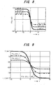
- Fig. 8 shows a nonlinear function F(x, ⁇ E) when the difference ⁇ E mn is the parameter.
- Fig. 9 shows the characteristics of the nonlinear functions F(x, ⁇ E 1 + ⁇ E 2 ), F(x, ⁇ E 1 ), F(x, ⁇ E 2 ).
- Equation (19) is produced.
- Fig. 10 is a block diagram of a turbo receiver that estimates the probability ⁇ lnP 1 (i 1 /y(t)) of the first bit i 1 of the first channel by means of Equation (13) in which blocks are rendered by using the relations of Equations (18) and (19). The constitution of the blocks can be simplified by using the relations of Equations (18) and (19).
- the first channel/first bit i 1 turbo receiver is constituted by a receiver portion 31a and a symbol decision unit 32, wherein the receiver portion 31a comprises a correlation unit (may also be a matched filter) 61, an other channel decision result operation unit 62, an own channel second bit decision result operation unit 63, a nonlinear unit 64, a coefficient multiplication unit 65 and a synthesizer unit 66.
- the receiver portion 31a comprises a correlation unit (may also be a matched filter) 61, an other channel decision result operation unit 62, an own channel second bit decision result operation unit 63, a nonlinear unit 64, a coefficient multiplication unit 65 and a synthesizer unit 66.
- a first multiplication unit 61a, first integrator 61b, second multiplication unit 61c, and second integrator 61d of the correlation unit 61 integrate the results of multiplying the received signal y(t) by predetermined reference signals S 0 to S 15 and the multiplication unit 61e multiplies the output -4dy of the first integrator 61b by a.
- the other channel decision result operation unit 62 comprises adders 62a and 62b, wherein the adder 62a adds the probability ⁇ lnP 2 (i 2 ) of the second bit of the second channel to the output signal of the second integrator 61d and the adder 62b adds the probability ⁇ lnP 2 (i 1 ) of the first bit of the second channel to the output signal of the first integrator 61b that has been multiplied by a.
- the own channel decision result operation unit 63 comprises an adder 63a, wherein the adder 63a adds the probability ⁇ ln 1 (i 2 ) of the second bit of the first channel to the output signal of the second integrator 61d.
- the nonlinear unit 64a executes a nonlinear calculation of the third term on the right side of Equation (13), the nonlinear unit 64b executes a nonlinear calculation of the fourth term on the right side of Equation (13), and the nonlinear unit 64c executes a nonlinear calculation of the fifth term on the right side of Equation (13) .
- Each of the multiplication units 65a to 65c of the coefficient multiplication unit 65 calculates the third to fifth terms on the right side of Equation (13) by multiplying the output of the nonlinear units 64a to 64c by the constants 0.25 , 0.50, and 0.25 respectively, the synthesizer unit 66 adds the first to fifth terms on the right side of Equation (13) and outputs the probability ⁇ lnP 1 (i 1 /y(t)) of the first bit i 1 of the first channel, and the symbol decision unit 32 decides whether the code of the first bit i 1 is "+” or "-", that is, "0" or "1", depending on whether the probability ⁇ lnP 1 (i 1 /y(t)) is greater or smaller than 0.
- Equation (13) The probability ⁇ lnP 1 (i 1/ y(t)) is fed back to the turbo receiver of the second bit i 2 and to the turbo receivers of the first and second bits of the second channel.
- ⁇ lnP 1 (i 1 ) can also be added by the synthesizer unit 66.
- Fig. 10 can also be used when receiving the first bit q 1 of the Quadrature component of the first channel.
- the constitution of Fig. 10 can also be used when receiving the first bits i 1 and q 1 of the common mode component and Quadrature component of the second channel respectively.
- the reception posterior probability P 1 (i 2 /y(t)) of the first channel/second bit is obtained as the sum of the posterior probabilities of the signals S j corresponding to the transmission of the information bit i 2 .
- the dependency of i 1 on S j can be removed by averaging the signals for all the possible i 1 from Table 2.
- the reception posterior probabilities P 1 (i 2 /y(t)) of the channels of interest from Table 2 are written as below.
- Equations (20) and (21) Care must be taken to make the combinations of the signals S j in Equations (20) and (21) different from those in Equations (3) and (4).
- the same signal notation system as in Table 2 is used.
- Equations (22) and (23) are the same as Equations (6) and (7). The difference lies only in the combination. Hence, all the results obtained in appendix A can also be adopted for Equations (22) and (23).
- the following equations are obtained by applying the decision rules of Equation (8) for the second bit of the first channel (see appendix A).
- Equation (25) The decision expression for the second bit of Equation (25) can be regarded as complex in comparison with the decision expression for the first bit (Equation (13)). However, the linear part comprises symmetrical opposite terms as is clear from Equation (25). In order to avoid additional complexity, several approximations are introduced. First, the sum of two nonlinear functions of an actual argument x with symmetrical opposite terms as shown in Equation (26) may be considered.
- the larger the argument x the closer FS(x, ⁇ E 1 , ⁇ E 2 ) is to zero.
- Equation (26) corresponds to the correlation output signal y ( y ⁇ 2 N 0 ⁇ 0 T y ( t ) d t ) of the decision expression of Equation (25).
- the function FS (x, ⁇ E 1 , ⁇ E 2 ) is then equal to zero and the linear terms of Equation (25) can be approximated as follows: ⁇ ln P 1 ( i 2 ) ⁇ 8 ⁇ d 2 / N 0 + 0.25 ⁇ ( ln cosh ⁇ 0.5 ( ⁇ 2 ⁇ ⁇ d ⁇ y ⁇ ⁇ E 01 + ⁇ ln P 2 ( i 2 ) ) ⁇ ⁇ ln cosh ⁇ 0.5 ( ⁇ 2 ⁇ ⁇ d ⁇ y ⁇ ⁇ E 45 + ⁇ ln P 2 ( i 2 ) )
- Fig. 12 is a block diagram of a turbo receiver that estimates the probability ⁇ lnP 1 (i 2 /y(t)) of the second bit i 2 of the first channel by means of Equation (28), which, in a broad classification, is constituted by a receiver portion 31b and a symbol decision unit 33 , wherein the receiver portion 31b comprises a correlation unit (may be a matched filter) 71, an other channel decision result operation unit 72, an own channel first bit decision result operation unit 73, first to third nonlinear units 74 to 76, a calculation unit 77, and an adder 78.
- a correlation unit may be a matched filter
- the first multiplication unit 71a, first integrator 71b, second multiplication unit 71c, second integrator 71d, third multiplication unit 71e and third integrator 71f of the correlation unit 71 integrate the results of multiplying the received signal y(t) by predetermined reference signals S 0 to S 15 .
- the other channel decision result operation unit 72 comprises adders 72a and 72b, wherein the adder 72a adds the probability ⁇ lnP 2 (i 2 ) of the second bit of the second channel to the output signal of the second integrator 71d and the adder 72b adds the probability ⁇ lnP 2 (i 1 ) of the first bit of the second channel to the output signal of the third integrator 71f.
- the first nonlinear unit 74a executes a first nonlinear calculation in the third term on the right side of Equation (28) and the other first nonlinear unit 74b executes a first nonlinear calculation in the fourth term on the right side of Equation (28) .
- the second nonlinear unit 75a executes a first nonlinear calculation in the third term on the right side of Equation (28) and the other second nonlinear unit 75b executes a second nonlinear calculation in the fourth term on the right side of Equation (28) .
- a multiplier 77a of the multiplication unit 77 calculates -6dy in the third term on the right side of Equation 28; an adder 77c adds -6dy, the output of the first nonlinear unit 74a and the output of the second nonlinear unit 75a; a multiplier 77b calculates -2dy in the fourth term on the right side of Equation (28) ; and the adder 77d adds -2dy, the output of the first nonlinear unit 74b and the output of the second nonlinear unit 75b.
- the own channel decision result operation unit 73 outputs signals A and B by adding the probability ⁇ lnP 1 (i 1 ) of the first bit of the first channel to the output signal of the adders 77c and 77d.
- the third nonlinear unit 76 executes the nonlinear calculation ln cosh[A]+ ln cosh[B], the adder 78 outputs the probability ⁇ lnP 1 (i 2 /y(t)) by adding -8d 2 /N 0 to the output of the third nonlinear unit 76, and the symbol decision unit 33 decides whether the code of the second bit i 2 is "+" or "-", that is, "0" or "1", depending on whether the probability ⁇ lnP 1 (i 2 /y(t)) is greater or smaller than 0.
- the probability ⁇ lnP 1 (i 2 /y(t)) is fed back to the turbo receiver portion of the first bit i 1 and to the turbo receiver portions of the first and second bits of the second channel.
- the adder 78 can be constituted such that ⁇ lnP 1 (i 2 )-8d 2 /N 0 is added instead of -8d 2 /N 0 .
- Fig. 12 can also be used when receiving the second bit q 2 of the Quadrature component of the first channel.
- the constitution of Fig. 12 can also be used when receiving the second bits i 2 and q 2 of the common mode component and Quadrature component of the second channel respectively.
- Fig. 13 is a constitutional view of the receiver of the first and second channels in which the same numerals are assigned to the same parts as in Figs. 7, 10, and 12.
- the receiver unit 30 of the first channel and the receiver unit 40 of the second channel have the same constitution. That is, the first channel/first bit turbo receiver portion (31a, 32) and the second channel/first bit turbo receiver portion (41a, 42) have the same constitution. Further, the first channel/second bit turbo receiver portion (31b, 33) and second channel/second bit turbo receiver portion (41b, 43) have the same constitution.
- the first channel/first bit turbo receiver portion 31a estimates the first channel/first bit probability ⁇ lnP 1 (i 1 /y(t)) by using the first channel/second bit probability ⁇ 1nP 1 (i 2 ) and the probabilities ⁇ 1nP 2 (i 1 ) and ⁇ 1nP 2 (i 2 ) of the first and second bits of the second channel respectively and the symbol decision unit 32 judges the first channel/first bit on the basis of the probability ⁇ lnP 1 (i 1 /y(t)).
- the first channel/second bit turbo receiver 31b estimates the first channel/second bit probability ⁇ lnP 1 (i 2 /y(t)) by using the first channel/first bit probability ⁇ lnP 1 (i 1 ) and the probabilities ⁇ lnP 2 (i 1 ) and ⁇ lnP 2 (i 2 ) of the first and second bits of the second channel respectively and the symbol decision unit 33 judges the first channel/second bit on the basis of the probability ⁇ lnP 1 (i 2 /y(t)).
- the second channel/first bit turbo receiver portion 41a estimates the second channel/first bit probability ⁇ lnP 2 (i 1 /y(t)) by using the second channel/second bit probability ⁇ lnP 2 (i 2 ) and the probabilities ⁇ lnP 1 (i 1 ) and ⁇ lnP 1 (i 2 ) of the first and second bits of the first channel respectively and the symbol decision unit 42 judges the second channel/first bit on the basis of the probability ⁇ lnP 2 (i 1/ y(t)).
- the second channel/second bit turbo receiver portion 41b estimates the second channel/second bit probability ⁇ lnP 2 (i 2 / Y (t)) by using the second channel/first bit probability ⁇ lnP 2 (i 1 ) and the probabilities ⁇ lnP 1 (i 1 ) and ⁇ lnP 1 (i 2 ) of the first and second bits of the first channel respectively and the symbol decision unit 43 judges the second channel/second bit on the basis of the probability ⁇ lnP 2 (i 2 /y(t)).
- the first and second bits of a Quadrature component can also be demodulated and outputted by means of the same constitution.
- Equations (13) and (28) define the constitution of the optimal receiver for a 16 QAM signal with ICI.
- decision information prior probability logarithm difference
- this information is ⁇ lnP 1 (i 1 ), ⁇ lnP 2 (i 2 ), and ⁇ lnP 2 (i 1 ), which denote the logarithm difference of the posterior probability (soft decision) of whether the codes of the transmitted bits of the first and second channels are "+" or "-” . Because all the calculations are performed serially, iterative counting to adopt the latest posterior probability from the first and second channels is possible during the processing according to Equation (13).
- the turbo connection between the two-channel soft decisions is as shown in Fig. 13.
- the proposed algorithm is analogous to the turbo decoder method of M.C. Valeniti and B.D. Woerner, "Variable latency turbo codes for wireless multimedia applications," Proc, Int. Symposium on Turbo codes and Related Topics., Brest, France, Sept. 1997, pp216-219, which was designed for turbo codes.
- the algorithm of the present invention shall be called a turbo receiver.
- the well-known Viterbi phrase that information that is beneficial to a decision is not discarded at all until all decisions are complete is extremely good and suited to the turbo receiver of the present invention.
- each decoder passes information to the other decoder and then closely examines the posterior probabilities that are estimated sequentially by using information that is derived from the other decoder.
- information that is derived following nonlinear processing from the first subchannel is used to examine closely the estimated posterior probability of the second channel, while information that is derived from the second channel is similarly used to examine closely the estimated posterior probability of the first channel.
- the algorithm of the present invention performs one or more iterations before making a final decision with respect to a received information symbol.
- hard bit decision is analogous to the decision feedback equalizer proposed for the purpose of ICI cancellation by Viterbi and Fazel in Viterbi and K. Fazel, " How to combat long echoes in OFDM transmission schemes: Subchannel equalization or more powerful channel coding," Proc. IEEE Globecom '95, Singapore, Nov. 1995, pp. 2069-2074.
- the hard bit decision is performed only in the final iteration.
- the algorithm of the present invention performs one or more iterations before making the final decision with respect to the received information.
- the values of ⁇ lnP 2 (i 1 ) and ⁇ lnP 2 (i 2 ) obtained in the previous step must be applied to Equation (28), which is the decision expression.
- the output of a channel receiver is used as the prior probability of the other receiver.
- A is a constellation of the original 16 QAM signal
- C) is a constellation of the received signal (16 QAM signal that has deteriorated due to noise)
- (D) is a constellation of the initial 16 QAM signal, of the present invention
- (E) is a constellation of a 16 QAM signal that has undergone two turbo iterations.
- the receiver of the present invention adopts a nonlinear unit and crossfeed in order to improve the estimation of the posterior probability.
- This constitution signifies that, though not impossible, an analysis of the BER performance is extremely difficult.
- a computer simulation was carried out in order to demonstrate that the nonlinear signal processing of the present invention was superior to that of a classical matched filter receiver.
- Figs. 15 and 16 show the average BER performance (written as 2Turbo) of the first bit i 1 and second bit i 2 of the receiver of the present invention as the function 2Eb/N 0 based on Equations (13) and (28) respectively.
- Eb/N 0 is the ratio between the background noise power spectral intensity No per bit and the average received signal energy Eb.
- 2Turbo is the result of the present invention following two turbo iterations.
- DFEs Decision Feedback Equalizers
- the receiver of the present invention is a receiver based on the estimated posterior probability.
- This receiver is a turbo receiver in which the receiver of each subchannel passes information to the receiver of the adjacent subchannel and sequentially refines the posterior probability that is estimated using information derived from the receiver of the adjacent subchannel.
- the turbo receiver of the present invention can substantially improve BER performance in comparison with a conventional matched filter receiver. This is because the nonlinear signal processing uses information that is obtained on the adjacent channel to maximize the posterior probability.
- the present invention executes a DFE equalizer that is widely used in order to cancel ICI by means of intelligent feedback. The largest BER improvement is produced in a high S/N ratio area where ICI governs Gaussian noise. According to the simulation results, the turbo receiver of the present invention is able to achieve a favorable performance over a substantially wide range of ICI coupling coefficients.
- Equation A (0) and Table 2 The following equation is obtained from Equation A (0) and Table 2.
- Equation A(0) and Table 2 The following equation is obtained from Equation A(0) and Table 2.
- Equations (10) and (11) ln cosh ⁇ 0.5 ⁇ ( ln P 1 ( 11 ) ⁇ ln P 1 ( 10 ) + ln ( P ( S 0 ) P 2 ( 11 ) + P ( S 1 ) P 2 ( 10 ) + P ( S 2 ) P 2 ( 01 ) + P ( S 3 ) P 2 ( 00 ) ) ⁇ ln ( P ( S 4 ) P 2 ( 11 ) + P ( S 5 ) P 2 ( 10 ) + P ( S 6 ) P 2 ( 01 ) + P ( S 7 ) P 2 ( 00 ) ) ) ⁇ and ln cosh ⁇ 0.5 ⁇ ( ln P 1 ( 01 ) ⁇ ln P 1 ( 00 ) + ln ( P ( S 8 ) P 2 ( 11 ) + P ( S 9 ) P 2 ( 10 ) + P ( S 10 )
- Equations A(5) and A(6) are approximated by means of each of the following equations.
Landscapes
- Engineering & Computer Science (AREA)
- Power Engineering (AREA)
- Computer Networks & Wireless Communication (AREA)
- Signal Processing (AREA)
- Digital Transmission Methods That Use Modulated Carrier Waves (AREA)
- Error Detection And Correction (AREA)
- Detection And Prevention Of Errors In Transmission (AREA)
- Radio Transmission System (AREA)
Applications Claiming Priority (1)
| Application Number | Priority Date | Filing Date | Title |
|---|---|---|---|
| JP2004265071A JP4472473B2 (ja) | 2004-09-13 | 2004-09-13 | 受信装置及び通信システム |
Publications (3)
| Publication Number | Publication Date |
|---|---|
| EP1635526A2 true EP1635526A2 (de) | 2006-03-15 |
| EP1635526A3 EP1635526A3 (de) | 2012-03-21 |
| EP1635526B1 EP1635526B1 (de) | 2013-11-13 |
Family
ID=35427393
Family Applications (1)
| Application Number | Title | Priority Date | Filing Date |
|---|---|---|---|
| EP05250281.2A Expired - Lifetime EP1635526B1 (de) | 2004-09-13 | 2005-01-20 | Weichentscheidungen bei Nachbarkanalstörungen |
Country Status (3)
| Country | Link |
|---|---|
| US (1) | US7505524B2 (de) |
| EP (1) | EP1635526B1 (de) |
| JP (1) | JP4472473B2 (de) |
Families Citing this family (9)
| Publication number | Priority date | Publication date | Assignee | Title |
|---|---|---|---|---|
| JP4516478B2 (ja) * | 2005-05-20 | 2010-08-04 | 富士通株式会社 | M−ary−QAMMIMO通信システムのための受信装置 |
| WO2007044484A2 (en) * | 2005-10-07 | 2007-04-19 | University Of Washington | Dirty paper precoding with known interference structure at receiver |
| US7983373B2 (en) * | 2007-02-07 | 2011-07-19 | Vintomie Networks B.V., Llc | Clock distribution for 10GBase-T analog front end |
| US8340202B2 (en) * | 2010-03-11 | 2012-12-25 | Telefonaktiebolaget Lm Ericsson (Publ) | Method and apparatus for efficient soft modulation for gray-mapped QAM symbols |
| WO2013097088A1 (en) * | 2011-12-27 | 2013-07-04 | France Telecom Research & Development Beijing Company Limited | Method and system for mapping bit sequences |
| CN105163398B (zh) | 2011-11-22 | 2019-01-18 | 华为技术有限公司 | 连接建立方法和用户设备 |
| WO2014130554A1 (en) * | 2013-02-19 | 2014-08-28 | Huawei Technologies Co., Ltd. | Frame structure for filter bank multi-carrier (fbmc) waveforms |
| CN111160407B (zh) * | 2019-12-10 | 2023-02-07 | 重庆特斯联智慧科技股份有限公司 | 一种深度学习目标检测方法及系统 |
| CN112099057B (zh) * | 2020-09-17 | 2024-03-05 | 重庆大学 | 一种基于模糊逻辑的双门限协作gnss干扰检测算法 |
Family Cites Families (6)
| Publication number | Priority date | Publication date | Assignee | Title |
|---|---|---|---|---|
| KR100498752B1 (ko) * | 1996-09-02 | 2005-11-08 | 소니 가부시끼 가이샤 | 비트메트릭스를 사용한 데이터 수신장치 및 방법 |
| DE19738780A1 (de) | 1997-09-04 | 1999-03-11 | Thomson Brandt Gmbh | Verfahren und Schaltungsanordnung zur Korrektur von Phasen- und/oder Frequenzfehlern digitaler Multicarrier-Signale |
| JP2001308820A (ja) | 2000-04-25 | 2001-11-02 | Mitsubishi Electric Corp | 直交周波数分割多重信号受信装置 |
| US7346126B2 (en) * | 2001-11-28 | 2008-03-18 | Telefonaktiebolaget L M Ericsson (Publ) | Method and apparatus for channel estimation using plural channels |
| SG120921A1 (en) * | 2002-03-13 | 2006-04-26 | Ntt Docomo Inc | Mimo receiver and method of reception therefor |
| JP3930511B2 (ja) * | 2002-08-30 | 2007-06-13 | 富士通株式会社 | 受信装置及び通信システム |
-
2004
- 2004-09-13 JP JP2004265071A patent/JP4472473B2/ja not_active Expired - Fee Related
-
2005
- 2005-01-20 EP EP05250281.2A patent/EP1635526B1/de not_active Expired - Lifetime
- 2005-01-28 US US11/044,273 patent/US7505524B2/en not_active Expired - Fee Related
Non-Patent Citations (1)
| Title |
|---|
| None |
Also Published As
| Publication number | Publication date |
|---|---|
| EP1635526A3 (de) | 2012-03-21 |
| US20060056551A1 (en) | 2006-03-16 |
| JP2006081060A (ja) | 2006-03-23 |
| US7505524B2 (en) | 2009-03-17 |
| EP1635526B1 (de) | 2013-11-13 |
| JP4472473B2 (ja) | 2010-06-02 |
Similar Documents
| Publication | Publication Date | Title |
|---|---|---|
| US7173990B2 (en) | Joint equalization, soft-demapping and phase error correction in wireless system with receive diversity | |
| US8428165B2 (en) | Method and system for decoding OFDM signals subject to narrowband interference | |
| US7173973B2 (en) | Multiple-antenna partially coherent constellations for multi-carrier systems | |
| US8315342B2 (en) | Method and apparatus for simplified expected symbol value computation and interference cancellation in communication signal processing | |
| EP2293504B1 (de) | Verfahren und Vorrichtung zur Interferenzabschwächung in einem Basisband-OFDM-Empfänger | |
| KR20050006494A (ko) | 직접 계산 방식에 의한 코드화 직교 주파수 분할 다중화수신기의 채널 상태 평가 장치 및 그 방법 | |
| US7317761B2 (en) | Multi-carrier communication system and receiver thereof | |
| Sendrei et al. | Iterative receiver for clipped GFDM signals | |
| EP1635526B1 (de) | Weichentscheidungen bei Nachbarkanalstörungen | |
| CN101138212B (zh) | 用于复值符号的软解映射的方法 | |
| Dinis et al. | IB‐DFE receivers with space diversity for CP‐assisted DS‐CDMA and MC‐CDMA systems | |
| US7274744B2 (en) | Multicarrier communication system and reception device for same | |
| EP1536581B1 (de) | System und Vorrichtung unter Verwendung weicher Entscheidungen in einem Mehrträgerübertragungssystem | |
| US7313191B2 (en) | Receiver device of communication system | |
| JP3930511B2 (ja) | 受信装置及び通信システム | |
| US7376196B2 (en) | Receiving apparatus in communication system | |
| Pokamestov et al. | Analysis of the downlink channel estimation methods in communication systems with SCMA | |
| Arthi | Performance Analysis of Multi Carrier CDMA Transceiver System using a Novel Dynamic Decoding and Scheduling Procedure | |
| JP4187555B2 (ja) | 通信システム及び受信装置 | |
| KR100556448B1 (ko) | 디매핑방법및장치 | |
| Caus et al. | Low-complexity interference variance estimation methods for coded multicarrier systems: application to SFN | |
| Torrieri | Iterative channel estimation, demodulation, and decoding | |
| Lau | Performance of simple pilot-symbol-aided algorithms over mobile radio channels |
Legal Events
| Date | Code | Title | Description |
|---|---|---|---|
| PUAI | Public reference made under article 153(3) epc to a published international application that has entered the european phase |
Free format text: ORIGINAL CODE: 0009012 |
|
| AK | Designated contracting states |
Kind code of ref document: A2 Designated state(s): AT BE BG CH CY CZ DE DK EE ES FI FR GB GR HU IE IS IT LI LT LU MC NL PL PT RO SE SI SK TR |
|
| AX | Request for extension of the european patent |
Extension state: AL BA HR LV MK YU |
|
| PUAL | Search report despatched |
Free format text: ORIGINAL CODE: 0009013 |
|
| AK | Designated contracting states |
Kind code of ref document: A3 Designated state(s): AT BE BG CH CY CZ DE DK EE ES FI FR GB GR HU IE IS IT LI LT LU MC NL PL PT RO SE SI SK TR |
|
| AX | Request for extension of the european patent |
Extension state: AL BA HR LV MK YU |
|
| RIC1 | Information provided on ipc code assigned before grant |
Ipc: H04L 25/06 20060101AFI20120214BHEP |
|
| 17P | Request for examination filed |
Effective date: 20120917 |
|
| AKX | Designation fees paid |
Designated state(s): DE FR GB |
|
| 17Q | First examination report despatched |
Effective date: 20121119 |
|
| GRAP | Despatch of communication of intention to grant a patent |
Free format text: ORIGINAL CODE: EPIDOSNIGR1 |
|
| INTG | Intention to grant announced |
Effective date: 20130606 |
|
| GRAS | Grant fee paid |
Free format text: ORIGINAL CODE: EPIDOSNIGR3 |
|
| GRAA | (expected) grant |
Free format text: ORIGINAL CODE: 0009210 |
|
| AK | Designated contracting states |
Kind code of ref document: B1 Designated state(s): DE FR GB |
|
| REG | Reference to a national code |
Ref country code: GB Ref legal event code: FG4D |
|
| REG | Reference to a national code |
Ref country code: DE Ref legal event code: R096 Ref document number: 602005041839 Country of ref document: DE Effective date: 20140109 |
|
| REG | Reference to a national code |
Ref country code: DE Ref legal event code: R097 Ref document number: 602005041839 Country of ref document: DE |
|
| PLBE | No opposition filed within time limit |
Free format text: ORIGINAL CODE: 0009261 |
|
| STAA | Information on the status of an ep patent application or granted ep patent |
Free format text: STATUS: NO OPPOSITION FILED WITHIN TIME LIMIT |
|
| 26N | No opposition filed |
Effective date: 20140814 |
|
| REG | Reference to a national code |
Ref country code: DE Ref legal event code: R097 Ref document number: 602005041839 Country of ref document: DE Effective date: 20140814 |
|
| REG | Reference to a national code |
Ref country code: FR Ref legal event code: PLFP Year of fee payment: 12 |
|
| REG | Reference to a national code |
Ref country code: FR Ref legal event code: PLFP Year of fee payment: 13 |
|
| REG | Reference to a national code |
Ref country code: FR Ref legal event code: PLFP Year of fee payment: 14 |
|
| PGFP | Annual fee paid to national office [announced via postgrant information from national office to epo] |
Ref country code: FR Payment date: 20191216 Year of fee payment: 16 |
|
| PGFP | Annual fee paid to national office [announced via postgrant information from national office to epo] |
Ref country code: DE Payment date: 20200107 Year of fee payment: 16 Ref country code: GB Payment date: 20200113 Year of fee payment: 16 |
|
| REG | Reference to a national code |
Ref country code: DE Ref legal event code: R119 Ref document number: 602005041839 Country of ref document: DE |
|
| GBPC | Gb: european patent ceased through non-payment of renewal fee |
Effective date: 20210120 |
|
| PG25 | Lapsed in a contracting state [announced via postgrant information from national office to epo] |
Ref country code: FR Free format text: LAPSE BECAUSE OF NON-PAYMENT OF DUE FEES Effective date: 20210131 |
|
| PG25 | Lapsed in a contracting state [announced via postgrant information from national office to epo] |
Ref country code: DE Free format text: LAPSE BECAUSE OF NON-PAYMENT OF DUE FEES Effective date: 20210803 Ref country code: GB Free format text: LAPSE BECAUSE OF NON-PAYMENT OF DUE FEES Effective date: 20210120 |