EP1635152A2 - Metering apparatus - Google Patents
Metering apparatus Download PDFInfo
- Publication number
- EP1635152A2 EP1635152A2 EP05255541A EP05255541A EP1635152A2 EP 1635152 A2 EP1635152 A2 EP 1635152A2 EP 05255541 A EP05255541 A EP 05255541A EP 05255541 A EP05255541 A EP 05255541A EP 1635152 A2 EP1635152 A2 EP 1635152A2
- Authority
- EP
- European Patent Office
- Prior art keywords
- cavity
- metering apparatus
- fluid
- metering
- drain
- Prior art date
- Legal status (The legal status is an assumption and is not a legal conclusion. Google has not performed a legal analysis and makes no representation as to the accuracy of the status listed.)
- Withdrawn
Links
- 239000012530 fluid Substances 0.000 claims abstract description 57
- 238000004891 communication Methods 0.000 claims abstract description 16
- 238000002347 injection Methods 0.000 claims description 26
- 239000007924 injection Substances 0.000 claims description 26
- 238000012360 testing method Methods 0.000 claims description 15
- 238000012937 correction Methods 0.000 claims description 8
- 239000000446 fuel Substances 0.000 claims description 4
- 239000011521 glass Substances 0.000 claims description 4
- 238000012935 Averaging Methods 0.000 claims description 3
- 229910000831 Steel Inorganic materials 0.000 claims description 2
- 229910001220 stainless steel Inorganic materials 0.000 claims description 2
- 239000010935 stainless steel Substances 0.000 claims description 2
- 239000010959 steel Substances 0.000 claims description 2
- 238000010276 construction Methods 0.000 description 4
- 230000001960 triggered effect Effects 0.000 description 4
- 238000010586 diagram Methods 0.000 description 3
- 238000000034 method Methods 0.000 description 2
- 230000006835 compression Effects 0.000 description 1
- 238000007906 compression Methods 0.000 description 1
- 239000013078 crystal Substances 0.000 description 1
- 230000001419 dependent effect Effects 0.000 description 1
- 230000000694 effects Effects 0.000 description 1
- 239000000463 material Substances 0.000 description 1
- 238000005259 measurement Methods 0.000 description 1
- 230000005499 meniscus Effects 0.000 description 1
- 238000012986 modification Methods 0.000 description 1
- 230000004048 modification Effects 0.000 description 1
- 238000004064 recycling Methods 0.000 description 1
- 230000035939 shock Effects 0.000 description 1
- 230000001360 synchronised effect Effects 0.000 description 1
Images


Classifications
-
- F—MECHANICAL ENGINEERING; LIGHTING; HEATING; WEAPONS; BLASTING
- F02—COMBUSTION ENGINES; HOT-GAS OR COMBUSTION-PRODUCT ENGINE PLANTS
- F02M—SUPPLYING COMBUSTION ENGINES IN GENERAL WITH COMBUSTIBLE MIXTURES OR CONSTITUENTS THEREOF
- F02M65/00—Testing fuel-injection apparatus, e.g. testing injection timing ; Cleaning of fuel-injection apparatus
- F02M65/002—Measuring fuel delivery of multi-cylinder injection pumps
-
- G—PHYSICS
- G01—MEASURING; TESTING
- G01F—MEASURING VOLUME, VOLUME FLOW, MASS FLOW OR LIQUID LEVEL; METERING BY VOLUME
- G01F1/00—Measuring the volume flow or mass flow of fluid or fluent solid material wherein the fluid passes through a meter in a continuous flow
- G01F1/007—Measuring the volume flow or mass flow of fluid or fluent solid material wherein the fluid passes through a meter in a continuous flow by measuring the level variations of storage tanks relative to the time
-
- G—PHYSICS
- G01—MEASURING; TESTING
- G01F—MEASURING VOLUME, VOLUME FLOW, MASS FLOW OR LIQUID LEVEL; METERING BY VOLUME
- G01F23/00—Indicating or measuring liquid level or level of fluent solid material, e.g. indicating in terms of volume or indicating by means of an alarm
- G01F23/14—Indicating or measuring liquid level or level of fluent solid material, e.g. indicating in terms of volume or indicating by means of an alarm by measurement of pressure
- G01F23/18—Indicating, recording or alarm devices actuated electrically
Definitions
- the present invention relates to metering apparatus comprising wall portions which define an elongate generally upright cavity of substantially uniform cross-section and an inlet to the cavity to enable fluid which is to be metered to be fed into the cavity.
- Such apparatus which has previously been proposed comprises graduated glass tubular columns into which test oil is fed from an injector pump under test via an injector. Readings can be taken after a known number of injections to provide a mean value of the amount of fluid passing through the injector with each injection.
- the apparatus does not lend itself to providing a digital readout, such as can be readily processed by a computer.
- the present invention seeks to provide a remedy.
- the present invention is directed to metering apparatus as set out in the opening paragraph of the present specification characterised by a pressure transducer which is in communication with fluid in the cavity when the apparatus is in use, to provide a signal which is indicative of the amount of fluid in the cavity above the transducer.
- the wall portions are provided by a tubular column.
- the column may be made of glass, or steel, for example stainless steel or any other suitable material.
- Such apparatus can be customised to any flow rate of fluid feed into the cavity by appropriate replacement of the columns to ones having different cross-sectional areas and different heights.
- the output from the transducer is connected to a calculator which converts the output from the pressure transducer to a value indicative of the volume of fluid above the transducer. This provides a reading which is more readily recognised in accordance with industry standards.
- transducer in communication with the base of the cavity. This makes use of substantially the whole of the volume of the cavity, and facilitates a relatively easy draining procedure whilst minimising dead space in the cavity which would need to be filled after a drain before a reading could be taken.
- a temperature measuring device is provided so as to be in communication with the fluid in the cavity when the apparatus is in use. This enables corrections to be made, for example to take account of changes in viscosity with temperature that will effect the rate of flow of fluid which wets the cavity wall portions after a drain of the cavity.
- Such a calculator is preferably programmed to allow for an exponentially decaying rate of flow down the cavity wall portions owing to fluid which has wetted those portions.
- a calculator is provided in any case at least to convert the signal from the pressure transducer to one which is indicative of the volume of fluid in the cavity required to give such a reading with the temperature of the fluid being 40°C. This enables a reading to be provided in accordance with industry standards.
- the temperature measuring device may most effectively be a thermistor or a thermocouple.
- the inlet is at the base of the cavity. This reduces the time it takes for the volume of fluid injected to be indicated by the pressure transducer.
- the cavity is provided with an outlet and the outlet is provided with a drain valve to enable fluid to be drained from the cavity.
- the apparatus is most effective as fuel injector test apparatus having at least one output line of an injector pump connected to feed fluid to the cavity via a fuel injector.
- the metering apparatus may measure the output of fluid from the nozzle of the or each injector, or it may be used to measure the bypass output from the injector. Respective metering apparatus may be provided for the nozzle output and the bypass output.
- the metering apparatus may have a separate cavity for each line of the injection pump which is to be tested.
- Respective drain valves for the cavities may also be provided, although it is possible, where accuracy is less important, to have more than one cavity sharing a drain valve.
- the calculator may be provided with a measure of the height of the fluid in the cavity immediately prior to a drain, as well as the time taken between a drain and a given reading, as well as the temperature indicated by the temperature measuring device, to provide a correction for wetted walls. This allows for correction for the fluid remaining on the walls influenced by the temperature dependent viscosity of the fluid, as well as the wall area which has been wetted and the time allowed for fluid to flow downwardly along the wetted walls.
- a delay device may be provided to ensure a steady state is reached after a drain before readings are taken.
- the delay device may count the number of injections that have been made since the last drain, or, alternatively, the device may ensure a fixed time delay after a drain before readings are commenced.
- memory means are included as part of the apparatus to maintain a tally of readings taken over a given period.
- the apparatus may also include averaging means to provide a measure of the average injected volume over a set of injections, for example one hundred injections.
- the apparatus may also be provided with display apparatus connected to display the readings taken, for example in the form of histograms and/or numerical indications.
- the calculator and/or the memory and/or the display apparatus may be provided by a readily available computer, such as a PC.
- the apparatus may be provided with collector means to enable the collection of fluid from the cavity or the cavities when it or they are drained, to facilitate a gravimetric calibration of the apparatus.
- the pressure transducer may be coupled to a separate cavity which does not empty when the said generally upright cavity is drained. This ensures that the pressure transducer is always wetted, and is not rendered inaccurate by contact with air.
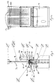
- the metering apparatus 10 shown in Figures 1 to 3 comprises a plurality of parallel upright tubular glass columns 12 arranged alongside one another in a generally planar configuration, the columns being divided into two groups of six with a larger space between the groups than between adjacent columns of each group.
- the apparatus is suitable for testing the injection pump of a diesel engine designed to power a heavy vehicle or plant.
- a different number of cylinders could be provided to test the injector of an engine having a different number of cylinders, and even one column would be useful.
- each column 12 is supported by a frame 14 as are other components of the apparatus now to be described.
- the base of each column 12 is supported in a block 16.
- each column 12 defines by its wall portions an elongate generally upright cavity 18 of substantially uniform cross-section extending upwardly from its associated block 16.
- Each block 16 itself is provided with a number of bores and cavities to accommodate a fluid inlet pipe 20 which is in communication with the cavity 18, a thermistor 22 which is also in communication with fluid in the cavity 18, a pressure transducer pipe 23 which is in communication with the fluid in the cavity 18 via a further cavity 26 defined by an inner block 28 which is within the block 16, the pipe 23 being in communication with a board-mounted pressure transducer 24, and an outlet 30 from the cavity 18 leading to a chute 32 via a solenoid valve 34 operated by a solenoid 36.
- the chutes 32 enable drained test oil from the columns 12 to be collected, and either returned to a reservoir (not shown) for recycling or used in a gravimetric calibration of the apparatus.
- the pressure transducer 24 is provided to give an indication of the amount of fluid in the cavity 18 of the column 12 which is above it.
- the valve 34 is closed with an O-ring seal 48 which is closest to the base of the column 12 urged against and surrounding a generally circular aperture 50 in the block 16 constituting part of the outlet from the cavity 18. This is the position of the valve 34 when the solenoid 36 is energised with a projecting arm 52 thereof in its extended position.
- the arm 52 is automatically retracted so that a second O-ring 54 of the seal 34 on the opposite side of a flange 56 thereof to that of the seal 48, is urged against a wall 58 which is sealed against the block 16 and surrounds the arm 52 at a position beyond the spring 46.
- the outlet portion of the outlet part aperture 50 is in fluid communication with the chute 32 to enable any fluid in the column 12 to pass out through the aperture 50 down into the chute 32 and returned for example to a reservoir (not shown) for further use.
- the thermistor 22 is recessed in a bore 60 formed in the block 16, the bore 60 being in fluid communication with the cavity 18 of the column 12.
- the pressure transducer 24 is in communication with the auxiliary cavity in the form of a bore 26 which extends axially along the same axis as that of the column 12 and which is defined by a bore through the inner block 28 which itself is within a generally axial central bore 66 through the block 16 with clearance between the cylindrical outer walls of the inner block 28 and the cylindrical inner walls defining the bore 66 of the block 16.
- a further bore 68 extends through the block 16 and opens into the axial bore 66 perpendicular thereto at a position facing the inner block 28 and into the clearance between that inner block 28 and the outer block 16, so that the bore 68 is in communication with the cavity 18 of the column 12.
- This bore 68 constitutes an inlet to the cavity 18.
- the inlet connector pipe 20 facilitates connection of a feed line from an injector of a fluid injection pump to the bore 68 and thence to the cavity 18.
- the upper end 72 of the inner block 28 is chamfered, and the bore 26 through the inner block 28 flares at its upper end.
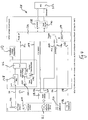
- Figure 4 shows the electrical circuitry of the apparatus shown in Figures 1 to 3. It comprises the printed circuit board 38 having inputs 110, 112, 114, 116 to which are connected the thermistor 22, the pressure transducer 24, a multiplexer 118 and a signal generator 120 which outputs a given number of pulses per revolution of the shaft of an injection pump (not shown) under test.
- the multiplexer 118 receives signals from a point of injection output 121 of the apparatus. This is taken from a signal generator (not shown) such as a piezoelectric crystal positioned to provide a pulse at each point of injection (POI). This is a useful instant, because at that moment shock waves from the injection will not have disturbed the fluid in the associated cavity, whilst the disturbance from the immediately preceding injection will have died away, thus reducing any errors from fluid disturbance.
- the multiplexer enables all of the point of injection signals to be passed to the printed circuit board 38, or alternatively only the points of injection of selected lines of the injector pump.
- the printed circuit board 38 has two outputs 122 and 124 connected respectively to the multiplexer 118 and to the solenoid 36 of the drain valve 34.
- the output 122 connected to the multiplexer 118 enables signals from the printed circuit board 38 to select which lines have their points of injection passed to the printed circuit board 38.
- the signal received at the input 110 is fed to an analogue to digital converter 126 via a low pass filter 128.
- the input 112 is connected to a main amplifier 130, the output of which is connected to one of the inputs of a differential amplifier 132 and which acts as a low pass filter and as an offset.
- the other input thereof is connected to a zero adjust potentiometer 134.
- the output from the differential amplifier 132 is fed to the analogue to digital converter 126.
- the printed circuit board 38 is provided with a main microprocessor 136 provided with an RS 232 interface 138 and a web server 140.
- the microprocessor 136 has inputs 142, 144 and 146 connected to receive signals respectively from the analogue to digital converter 126, the multiplexer 118 via the input 114, and the pulses from the revolution signal generator 120 via the input 116, respectively.
- the microprocessor 136 has outputs 148 and 150 connected respectively to the digital potentiometer 134 on the one hand and to the solenoid 136 via the output 124.
- a PC microcomputer 152 is connected via a network connection to the RS232 138 and the web server 140. The PC may be programmed to provide the display already referred to herein.
- the microprocessor 136 receives connections from each and every column 12 and is connected to energise and de-energise each and every solenoid 36 for the different lines which are being monitored.
- There is a sub-circuit comprising an analogue to digital converter 126 with associated low pass filter 128, amplifiers 130 and 132, and digital potentiometer 134 for each column 12, and each sub-circuit is provided with a precision voltage regulator 153 to ensure accuracy of readings taken.
- the microprocessor 136 is also provided with a timer 154 and analogue to digital converter trigger interrupt of the microprocessor 136 is connected via a three-way switch to the timer 154 or one of the inputs 114 and 116.
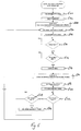
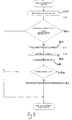
- FIG. 5 shows the a drain and fill program. From power up an initializing procedure involves de-energising each and every solenoid 36 at step 500. With reference to Figure 3, this causes retraction of the arm 52 of the solenoid 36 and opening of the valve 34 so that any fluid in the cavity 18 may drain through the aperture 50 and into the chute 32.
- a period of, for example, five seconds is counted by the microprocessor 136 at step 502 whereafter the initial pressure transducer offsets by the digital potentiometers 134 are removed at step 504. That period can be readily changed if required to improve accuracy.
- a minimum level read flag is set at false.
- a further de-energised command in relation to the solenoid 36 is issued at step 508 to be effective after the main loop of the program shown in Figure 5 has been completed.
- the program in accordance with which the microprocessor 136 is operated determines whether the apparatus has been switched to meter the flow of test oil from an injector pump under test by way of a control console (not shown).
- step 512 it queries whether all fluid levels in the various columns 12 are below a predetermined level indicating that they are empty. If they are not, the program loops back to reiterate the query at 512. Ultimately, since the drain valves are all open, the query will reveal that all the columns 12 are empty, whereupon the program will pass to step 514 where a delay period occurs to allow settling of the test oil. Then at the next step 516, the digital potentiometer 134 is again zeroed.
- step 518 in which the solenoid 36 is energised to close the valve 34 so that fluid passing in through the inlet 68 now starts to fill the cavity 18 of each and every column 12.
- step 520 a delay is built in to allow the valve 34 to respond.
- a query 522 to check whether any of the levels of test oil in the column 12 exceeds a predetermined maximum value. If the answer is 'no', then the query is raised to step 524 whether all the levels have exceeded a predetermined mimimum value sufficient to give significant readings. If the answer to that query is 'no', the program recycles to repeat the query at 522 as to whether any of the levels of test fluid in the columns 12 has exceeded the predetermined maximum level. Ultimately, bearing in mind the solenoids 36 have been switched to cause the cavity 18 to fill, the answer to the query 524 whether all levels exceeded a predetermined minimum will be 'yes', whereupon the query that the minimum level has been reached is set to 'true' at step 526.
- the manner in which successive readings in the analogue to digital converter 126 are taken up by the microprocessor 136 may be selected from three options. These three options are indicated in Figure 4 on the microprocessor box 136.
- a first option is to take readings for every point of injection, either for several lines or for lines selected via the microprocessor 136 and the multiplexer 118.
- the second option is to take readings at the instants determined by the pulse generator 120, for which there are two sub-options, option 2(a) effecting a reading at completion of every rotation of the main injection pump shaft, and option 2(b) effecting a reading from a pulse, which, as determined by a memorised pulse count, corresponds to a point of injection.
- the third option is to take readings with a uniform time spacing between successive readings as determined by the timer 154.
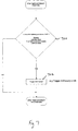
- the sub-routine by which the microprocessor 136 is programmed to operate to execute the second option is shown in Figure 6.
- This sub-routine commences every time a pulse from the signal generator 120 is received by the microprocessor 136. It starts with a query at step 600 as to whether or not a pulse count of the microprocessor 136 reads zero. If it does, the program passes to step 602 in which the count is reloaded with the number of pulses per revolution of the injector pump shaft generated by the pulse generator 120. If the pulse count is not zero at step 600, step 602 is bypassed via step 604 in which the count is decremented. At the next step 606 after step 602, the query is raised whether the revolution based mode (option 2a) has indeed been selected.
- step 608 the query is raised at step 608 as to whether or not a synchronous mode (option 2 b ), to check the readings at every count which corresponds to a point of injection, has been selected. If it has not, the sub-routine is ended. If it has, a query is raised at step 612 as to whether the count in the pulse counter is at a memorised point of injection. If so, the analogue to digital converter interrupt is triggered; if not, the sub-routine ends. Finally, it can be seen that if at step 606, the revolution based mode (option 2a) is selected, the program passes to step 610 to cause interruption of other operation of the microprocessor 136 and cause it to accept readings from the analogue to digital converter 126
- the query is raised whether draining, leak tester mode, time base flowmeter mode, or calibration mode is being effected at step 700. If so, the triggering of the analogue to digital converter interrupt occurs at step 702; otherwise the sub-routine ends.
- readings are taken in series of the pressure and temperature from the analogue to digital converter 126 at step 800. This is executed for each of the twelve columns 12.
- step 802 there follows a query at step 802 whether filling is occurring, whether the minimum level has been reached, and whether the measure count exceeds zero.
- the sub-routine is ended if any one of these conditions is 'false'. If they are all true, then for each of the twelve columns, the incremental pressure is calculated by the microprocessor 136 at step 804.
- the value of the memorised last pressure is equated to the current pressure, and at step 808, the measure count is decremented.
- the query is raised at step 810 as to whether the level count has reached zero. If it is not, then the program returns to step 802. If it has, then the measure count has reached the required number of measurements and the sub-routine is completed.
- the microprocessor 136 thus acts as a calculator which converts the output from the pressure transducer to value indicative of the increase in the volume of fluid above the transducer. Temperature corrections and wetted wall corrections as referred to herein are also effected by the microprocessor 136 at this stage. So can the averaging referred to herein also be effected.
- the embodiment of the present invention shown in Figures 9 to 15 comprises four columns 900. They share a common drain valve 910 and are provided with respective thermocouples 912 and respective pressure transducers 914. Such a construction is less accurate than the one shown in Figures 1 to 4 but is nonetheless sufficiently accurate for example to measure the bypass flow through injectors which are electrically triggered, but which use the pressure of fluid supplied to the injector to power operation of the injection.
Landscapes
- Engineering & Computer Science (AREA)
- Physics & Mathematics (AREA)
- Fluid Mechanics (AREA)
- General Physics & Mathematics (AREA)
- Chemical & Material Sciences (AREA)
- Combustion & Propulsion (AREA)
- Mechanical Engineering (AREA)
- General Engineering & Computer Science (AREA)
- Measuring Volume Flow (AREA)
Abstract
Description
- The present invention relates to metering apparatus comprising wall portions which define an elongate generally upright cavity of substantially uniform cross-section and an inlet to the cavity to enable fluid which is to be metered to be fed into the cavity.
- Such apparatus which has previously been proposed comprises graduated glass tubular columns into which test oil is fed from an injector pump under test via an injector. Readings can be taken after a known number of injections to provide a mean value of the amount of fluid passing through the injector with each injection.
- Apart from the inherent inaccuracy of such apparatus resulting from parallax errors in attempting to read the level of the meniscus of the test oil in a column, the apparatus does not lend itself to providing a digital readout, such as can be readily processed by a computer.
- The present invention seeks to provide a remedy.
- Accordingly, the present invention is directed to metering apparatus as set out in the opening paragraph of the present specification characterised by a pressure transducer which is in communication with fluid in the cavity when the apparatus is in use, to provide a signal which is indicative of the amount of fluid in the cavity above the transducer.
- Such apparatus benefits from very low back pressure.
- Preferably, the wall portions are provided by a tubular column. This is a readily available and relatively easily made construction having the required substantially uniform cross-section. The column may be made of glass, or steel, for example stainless steel or any other suitable material.
- Such apparatus can be customised to any flow rate of fluid feed into the cavity by appropriate replacement of the columns to ones having different cross-sectional areas and different heights.
- Preferably, the output from the transducer is connected to a calculator which converts the output from the pressure transducer to a value indicative of the volume of fluid above the transducer. This provides a reading which is more readily recognised in accordance with industry standards.
- It is desirable to have the transducer in communication with the base of the cavity. This makes use of substantially the whole of the volume of the cavity, and facilitates a relatively easy draining procedure whilst minimising dead space in the cavity which would need to be filled after a drain before a reading could be taken.
- In one preferred embodiment of the present invention, a temperature measuring device is provided so as to be in communication with the fluid in the cavity when the apparatus is in use. This enables corrections to be made, for example to take account of changes in viscosity with temperature that will effect the rate of flow of fluid which wets the cavity wall portions after a drain of the cavity.
- It is desirable to have the temperature measuring device connected to the calculator to enable such a correction to be made. Such a calculator is preferably programmed to allow for an exponentially decaying rate of flow down the cavity wall portions owing to fluid which has wetted those portions.
- Preferably, a calculator is provided in any case at least to convert the signal from the pressure transducer to one which is indicative of the volume of fluid in the cavity required to give such a reading with the temperature of the fluid being 40°C. This enables a reading to be provided in accordance with industry standards.
- The temperature measuring device may most effectively be a thermistor or a thermocouple.
- Preferably, the inlet is at the base of the cavity. This reduces the time it takes for the volume of fluid injected to be indicated by the pressure transducer.
- Preferably, the cavity is provided with an outlet and the outlet is provided with a drain valve to enable fluid to be drained from the cavity.
- It is desirable to have the outlet arranged at the base of the cavity to enable substantially the whole of the cavity to be drained of fluid.
- The apparatus is most effective as fuel injector test apparatus having at least one output line of an injector pump connected to feed fluid to the cavity via a fuel injector.
- The metering apparatus may measure the output of fluid from the nozzle of the or each injector, or it may be used to measure the bypass output from the injector. Respective metering apparatus may be provided for the nozzle output and the bypass output.
- The metering apparatus may have a separate cavity for each line of the injection pump which is to be tested.
- Respective drain valves for the cavities may also be provided, although it is possible, where accuracy is less important, to have more than one cavity sharing a drain valve.
- The calculator may be provided with a measure of the height of the fluid in the cavity immediately prior to a drain, as well as the time taken between a drain and a given reading, as well as the temperature indicated by the temperature measuring device, to provide a correction for wetted walls. This allows for correction for the fluid remaining on the walls influenced by the temperature dependent viscosity of the fluid, as well as the wall area which has been wetted and the time allowed for fluid to flow downwardly along the wetted walls.
- A delay device may be provided to ensure a steady state is reached after a drain before readings are taken. For example, the delay device may count the number of injections that have been made since the last drain, or, alternatively, the device may ensure a fixed time delay after a drain before readings are commenced.
- Preferably, memory means are included as part of the apparatus to maintain a tally of readings taken over a given period. The apparatus may also include averaging means to provide a measure of the average injected volume over a set of injections, for example one hundred injections. The apparatus may also be provided with display apparatus connected to display the readings taken, for example in the form of histograms and/or numerical indications.
- The calculator and/or the memory and/or the display apparatus may be provided by a readily available computer, such as a PC.
- The apparatus may be provided with collector means to enable the collection of fluid from the cavity or the cavities when it or they are drained, to facilitate a gravimetric calibration of the apparatus.
- The pressure transducer may be coupled to a separate cavity which does not empty when the said generally upright cavity is drained. This ensures that the pressure transducer is always wetted, and is not rendered inaccurate by contact with air.
- Examples of apparatus embodying the present invention will now be described with reference to the accompanying drawings, in which:
- Figure 1
- is a side elevational part-sectional view of metering apparatus embodying the present invention;
- Figure 2
- is a front elevational view of the apparatus shown in Figure 1 with parts removed for the sake of clarity;
- Figure 3
- is an axial sectional diagrammatic view of parts of the apparatus shown in Figure 1;
- Figure 4
- is a circuit diagram of the electrical circuitry of the apparatus shown in Figures 1 to 3;
- Figure 5
- is a flow diagram of a metering program in accordance with which the circuitry shown in Figure 4 operates;
- Figures 6 to 8
- show respective flow charts of sub-routines of the program by which circuitry shown in Figure 4 operates;
- Figure 9
- shows an elevated part cross-sectional part cut-away diagram of a variant embodiment of the present invention;
- Figure 10
- shows a side part cut-away elevational view of the apparatus shown in Figure 9;
- Figure 11
- shows a part cut-away plan view of the apparatus shown in Figure 9;
- Figure 12
- shows an elevated axial sectional view of parts of the apparatus shown in Figure 9;
- Figure 13
- shows a cross-sectional view through a part of the apparatus shown in Figure 12;
- Figure 14
- shows a diagonal diagrammatic cross-section of the apparatus shown in Figure 9; and
- Figure 15
- shows the diagonal cross-section of Figure 14 on a larger scale.
- The
metering apparatus 10 shown in Figures 1 to 3 comprises a plurality of parallel uprighttubular glass columns 12 arranged alongside one another in a generally planar configuration, the columns being divided into two groups of six with a larger space between the groups than between adjacent columns of each group. In this case, the apparatus is suitable for testing the injection pump of a diesel engine designed to power a heavy vehicle or plant. Clearly, a different number of cylinders could be provided to test the injector of an engine having a different number of cylinders, and even one column would be useful. - The
columns 12 are supported by aframe 14 as are other components of the apparatus now to be described. The base of eachcolumn 12 is supported in ablock 16. Thus, eachcolumn 12 defines by its wall portions an elongate generallyupright cavity 18 of substantially uniform cross-section extending upwardly from its associatedblock 16. Eachblock 16 itself is provided with a number of bores and cavities to accommodate afluid inlet pipe 20 which is in communication with thecavity 18, athermistor 22 which is also in communication with fluid in thecavity 18, apressure transducer pipe 23 which is in communication with the fluid in thecavity 18 via afurther cavity 26 defined by aninner block 28 which is within theblock 16, thepipe 23 being in communication with a board-mountedpressure transducer 24, and anoutlet 30 from thecavity 18 leading to achute 32 via asolenoid valve 34 operated by asolenoid 36. - The
chutes 32 enable drained test oil from thecolumns 12 to be collected, and either returned to a reservoir (not shown) for recycling or used in a gravimetric calibration of the apparatus. - The
pressure transducer 24 is provided to give an indication of the amount of fluid in thecavity 18 of thecolumn 12 which is above it. - Electrical connections (not shown in Figure 1) are made between a printed
circuit board 38 in ahousing 40 on the one hand and thethermistor 22, thepressure transducer 24 and thedrain valve solenoid 36 on the other. The upper ends of thecolumns 24 project upwardly into acommon overflow tray 42 downwardly from the bottom of which extends adrain outlet 44. - The construction of the
block 16 and the parts secured therein can be seen more readily in Figure 3. More especially, it can be seen that thesolenoid 36 is connected to avalve 34 via a direct link helical compression spring 46 to retract the valve. - The
valve 34, as shown in Figure 3, is closed with an O-ring seal 48 which is closest to the base of thecolumn 12 urged against and surrounding a generallycircular aperture 50 in theblock 16 constituting part of the outlet from thecavity 18. This is the position of thevalve 34 when thesolenoid 36 is energised with a projecting arm 52 thereof in its extended position. In the event that thesolenoid 36 is de-energised, the arm 52 is automatically retracted so that a second O-ring 54 of theseal 34 on the opposite side of aflange 56 thereof to that of the seal 48, is urged against awall 58 which is sealed against theblock 16 and surrounds the arm 52 at a position beyond the spring 46. With the arm 52 in a retracted position, the outlet portion of theoutlet part aperture 50 is in fluid communication with thechute 32 to enable any fluid in thecolumn 12 to pass out through theaperture 50 down into thechute 32 and returned for example to a reservoir (not shown) for further use. - It can be seen from Figure 3 that the
thermistor 22 is recessed in a bore 60 formed in theblock 16, the bore 60 being in fluid communication with thecavity 18 of thecolumn 12. Thepressure transducer 24 is in communication with the auxiliary cavity in the form of abore 26 which extends axially along the same axis as that of thecolumn 12 and which is defined by a bore through theinner block 28 which itself is within a generally axial central bore 66 through theblock 16 with clearance between the cylindrical outer walls of theinner block 28 and the cylindrical inner walls defining the bore 66 of theblock 16. - A further bore 68 extends through the
block 16 and opens into the axial bore 66 perpendicular thereto at a position facing theinner block 28 and into the clearance between thatinner block 28 and theouter block 16, so that the bore 68 is in communication with thecavity 18 of thecolumn 12. This bore 68 constitutes an inlet to thecavity 18. Theinlet connector pipe 20 facilitates connection of a feed line from an injector of a fluid injection pump to the bore 68 and thence to thecavity 18. - The
upper end 72 of theinner block 28 is chamfered, and thebore 26 through theinner block 28 flares at its upper end. As a result, although fluid may be drained completely from thecavity 18 by the opening of thevalve 34, fluid remains trapped in thebore 26 to ensure that thepressure transducer 24 is always in communication with fluid, in this case test oil, and does not suffer inaccuracy by being exposed to air. - Figure 4 shows the electrical circuitry of the apparatus shown in Figures 1 to 3. It comprises the printed
circuit board 38 havinginputs thermistor 22, thepressure transducer 24, amultiplexer 118 and asignal generator 120 which outputs a given number of pulses per revolution of the shaft of an injection pump (not shown) under test. - The
multiplexer 118 receives signals from a point of injection output 121 of the apparatus. This is taken from a signal generator (not shown) such as a piezoelectric crystal positioned to provide a pulse at each point of injection (POI). This is a useful instant, because at that moment shock waves from the injection will not have disturbed the fluid in the associated cavity, whilst the disturbance from the immediately preceding injection will have died away, thus reducing any errors from fluid disturbance. The multiplexer enables all of the point of injection signals to be passed to the printedcircuit board 38, or alternatively only the points of injection of selected lines of the injector pump. - The printed
circuit board 38 has twooutputs multiplexer 118 and to thesolenoid 36 of thedrain valve 34. - The
output 122 connected to themultiplexer 118 enables signals from the printedcircuit board 38 to select which lines have their points of injection passed to the printedcircuit board 38. - The signal received at the
input 110 is fed to an analogue todigital converter 126 via alow pass filter 128. - The
input 112 is connected to amain amplifier 130, the output of which is connected to one of the inputs of adifferential amplifier 132 and which acts as a low pass filter and as an offset. The other input thereof is connected to a zero adjustpotentiometer 134. The output from thedifferential amplifier 132 is fed to the analogue todigital converter 126. - The printed
circuit board 38 is provided with amain microprocessor 136 provided with an RS 232interface 138 and aweb server 140. Themicroprocessor 136 hasinputs digital converter 126, themultiplexer 118 via theinput 114, and the pulses from therevolution signal generator 120 via theinput 116, respectively. Themicroprocessor 136 hasoutputs 148 and 150 connected respectively to thedigital potentiometer 134 on the one hand and to thesolenoid 136 via theoutput 124. APC microcomputer 152 is connected via a network connection to theRS232 138 and theweb server 140. The PC may be programmed to provide the display already referred to herein. It will be appreciated that themicroprocessor 136 receives connections from each and everycolumn 12 and is connected to energise and de-energise each and everysolenoid 36 for the different lines which are being monitored. There is a sub-circuit comprising an analogue todigital converter 126 with associatedlow pass filter 128,amplifiers digital potentiometer 134 for eachcolumn 12, and each sub-circuit is provided with aprecision voltage regulator 153 to ensure accuracy of readings taken. - The
microprocessor 136 is also provided with atimer 154 and analogue to digital converter trigger interrupt of themicroprocessor 136 is connected via a three-way switch to thetimer 154 or one of theinputs - Operation of the apparatus and circuitry shown in Figures 1 to 4 will now be described with reference to the program and routines shown in Figures 5 to 8.
- Figure 5 shows the a drain and fill program. From power up an initializing procedure involves de-energising each and every
solenoid 36 at step 500. With reference to Figure 3, this causes retraction of the arm 52 of thesolenoid 36 and opening of thevalve 34 so that any fluid in thecavity 18 may drain through theaperture 50 and into thechute 32. - A period of, for example, five seconds is counted by the
microprocessor 136 at step 502 whereafter the initial pressure transducer offsets by thedigital potentiometers 134 are removed atstep 504. That period can be readily changed if required to improve accuracy. At step 506, a minimum level read flag is set at false. A further de-energised command in relation to thesolenoid 36 is issued at step 508 to be effective after the main loop of the program shown in Figure 5 has been completed. Atstep 510, the program in accordance with which themicroprocessor 136 is operated determines whether the apparatus has been switched to meter the flow of test oil from an injector pump under test by way of a control console (not shown). If no such command has been issued, the program is simply looped back to reiterate the query. Once it is noted that a metering command has been issued, the program passes to step 512 where it queries whether all fluid levels in thevarious columns 12 are below a predetermined level indicating that they are empty. If they are not, the program loops back to reiterate the query at 512. Ultimately, since the drain valves are all open, the query will reveal that all thecolumns 12 are empty, whereupon the program will pass to step 514 where a delay period occurs to allow settling of the test oil. Then at the next step 516, thedigital potentiometer 134 is again zeroed. The program then continues withstep 518 in which thesolenoid 36 is energised to close thevalve 34 so that fluid passing in through the inlet 68 now starts to fill thecavity 18 of each and everycolumn 12. At the next step 520, a delay is built in to allow thevalve 34 to respond. - There next follows in the program a
query 522 to check whether any of the levels of test oil in thecolumn 12 exceeds a predetermined maximum value. If the answer is 'no', then the query is raised to step 524 whether all the levels have exceeded a predetermined mimimum value sufficient to give significant readings. If the answer to that query is 'no', the program recycles to repeat the query at 522 as to whether any of the levels of test fluid in thecolumns 12 has exceeded the predetermined maximum level. Ultimately, bearing in mind thesolenoids 36 have been switched to cause thecavity 18 to fill, the answer to thequery 524 whether all levels exceeded a predetermined minimum will be 'yes', whereupon the query that the minimum level has been reached is set to 'true' at step 526. As time proceeds, since all thecavities 18 at thecolumn 12 are filling, at least one of the fluid levels will eventually exceed the predetermined maximum level. At this point, the program loops back to step 506 where the query indicating whether the minimum level has been reached for all thecolumns 12 be set to 'false' and the program is repeated from there. More especially, draining occurs at step 508. - The manner in which successive readings in the analogue to
digital converter 126 are taken up by themicroprocessor 136 may be selected from three options. These three options are indicated in Figure 4 on themicroprocessor box 136. A first option is to take readings for every point of injection, either for several lines or for lines selected via themicroprocessor 136 and themultiplexer 118. The second option is to take readings at the instants determined by thepulse generator 120, for which there are two sub-options, option 2(a) effecting a reading at completion of every rotation of the main injection pump shaft, and option 2(b) effecting a reading from a pulse, which, as determined by a memorised pulse count, corresponds to a point of injection. The third option is to take readings with a uniform time spacing between successive readings as determined by thetimer 154. - The sub-routine by which the
microprocessor 136 is programmed to operate to execute the second option is shown in Figure 6. This sub-routine commences every time a pulse from thesignal generator 120 is received by themicroprocessor 136. It starts with a query at step 600 as to whether or not a pulse count of themicroprocessor 136 reads zero. If it does, the program passes to step 602 in which the count is reloaded with the number of pulses per revolution of the injector pump shaft generated by thepulse generator 120. If the pulse count is not zero at step 600, step 602 is bypassed via step 604 in which the count is decremented. At thenext step 606 after step 602, the query is raised whether the revolution based mode (option 2a) has indeed been selected. If not, the query is raised at step 608 as to whether or not a synchronous mode (option 2b), to check the readings at every count which corresponds to a point of injection, has been selected. If it has not, the sub-routine is ended. If it has, a query is raised atstep 612 as to whether the count in the pulse counter is at a memorised point of injection. If so, the analogue to digital converter interrupt is triggered; if not, the sub-routine ends. Finally, it can be seen that if atstep 606, the revolution based mode (option 2a) is selected, the program passes to step 610 to cause interruption of other operation of themicroprocessor 136 and cause it to accept readings from the analogue todigital converter 126 - In the sub-routine shown in Figure 7, which is triggered every time a pulse is issued from the
timer 154, and is effective with theaforementioned option 3, the query is raised whether draining, leak tester mode, time base flowmeter mode, or calibration mode is being effected atstep 700. If so, the triggering of the analogue to digital converter interrupt occurs atstep 702; otherwise the sub-routine ends. - A corresponding subroutine exists for
option 1, which is triggered every time a pulse is received by themicroprocessor 136 from themultiplexer 118. - In the analogue to digital converter interrupt sub-routine shown in Figure 8, readings are taken in series of the pressure and temperature from the analogue to
digital converter 126 atstep 800. This is executed for each of the twelvecolumns 12. Next, there follows a query atstep 802 whether filling is occurring, whether the minimum level has been reached, and whether the measure count exceeds zero. The sub-routine is ended if any one of these conditions is 'false'. If they are all true, then for each of the twelve columns, the incremental pressure is calculated by themicroprocessor 136 atstep 804. Atstep 806, the value of the memorised last pressure is equated to the current pressure, and atstep 808, the measure count is decremented. Next the query is raised atstep 810 as to whether the level count has reached zero. If it is not, then the program returns to step 802. If it has, then the measure count has reached the required number of measurements and the sub-routine is completed. - From the incremental pressure the
microprocessor 136 thus acts as a calculator which converts the output from the pressure transducer to value indicative of the increase in the volume of fluid above the transducer. Temperature corrections and wetted wall corrections as referred to herein are also effected by themicroprocessor 136 at this stage. So can the averaging referred to herein also be effected. - The embodiment of the present invention shown in Figures 9 to 15 comprises four
columns 900. They share acommon drain valve 910 and are provided withrespective thermocouples 912 andrespective pressure transducers 914. Such a construction is less accurate than the one shown in Figures 1 to 4 but is nonetheless sufficiently accurate for example to measure the bypass flow through injectors which are electrically triggered, but which use the pressure of fluid supplied to the injector to power operation of the injection. - Other variations and modifications to the illustrated embodiments of the present invention may occur to the reader without taking the resulting construction outside the scope of the present invention.
Claims (34)
- Metering apparatus comprising wall portions which define an elongate generally upright cavity (18) of substantially uniform cross-section and an inlet to the cavity (18) to enable fluid which is to be metered to be fed into the cavity, characterised by a pressure transducer (24) which is in communication with fluid in the cavity (18) when the apparatus is in use, to provide a signal which is indicative of the amount of fluid in the cavity above the transducer (24).
- Metering apparatus according to claim 1, characterised in that the wall portions are provided by a tubular column (12).
- Metering apparatus according to claim 2, characterised in that the column is made of glass.
- Metering apparatus according to claim 2, characterised in that the column is made of steel.
- Metering apparatus according to claim 4, characterised in that the column is made of stainless steel.
- Metering apparatus according to any one of claims 2 to 5, characterised in that the column (12) is replaceable by a different column having a different cross-sectional area and a different height.
- Metering apparatus according to any preceding claim, characterised in that the pressure transducer is in communication with the base of the cavity (18).
- Metering apparatus according to any preceding claim, characterised in that the output from the transducer (24) is connected to a calculator (136) which converts the output from the pressure transducer (24) to a value indicative of the volume of fluid above the transducer (24).
- Metering apparatus according to any preceding claim, characterised in that a temperature measuring device (22) is provided so as to be in communication with the fluid in the cavity (18) when the apparatus is in use.
- Metering apparatus according to claim 9 read as appended to claim 8, characterised in that the temperature measuring device (22) is connected to the calculator (136) to enable a temperature correction to be made.
- Metering apparatus according to claim 8, or claim 9 or 10 read as appended to claim 8, characterised in that the calculator (136) is programmed to allow for an exponentially decaying rate of flow down the cavity wall portions owing to fluid which has wetted those portions.
- Metering apparatus according to any preceding claim, characterised in that the calculator (136) is programmed to convert the signal from the pressure transducer (24) to one which is indicative of the volume of fluid in the cavity (18) required to give such a reading with the temperature of the fluid being 40°C.
- Metering apparatus according to claim 9 or claim 10, or claim 11 or 12 read as appended to claim 9, characterised in that the temperature measuring device (22) is a thermistor (22).
- Metering apparatus according to claim 9 or claim 10, or claim 11 or 12 read as appended to claim 9, characterised in that the temperature measuring device (22) is a thermocouple.
- Metering apparatus according to any preceding claim, characterised in that the inlet (68) is at the base of the cavity (18).
- Metering apparatus according to any preceding claim, characterised in that the cavity (18) is provided with an outlet (30) and the outlet (30) is provided with a drain valve (34) to enable fluid to be drained from the cavity (18).
- Metering apparatus according to claim 16, characterised in that the outlet (30) is arranged at the base of the cavity (18).
- Metering apparatus according to any preceding claim, characterised in that the apparatus is fuel injector test apparatus having at least one output line of an injector pump connected to feed fluid to the cavity (18) via a fuel injector.
- Metering apparatus according to claim 18, characterised in that the apparatus is arranged to measure the output of fluid from the nozzle of the or each injector.
- Metering apparatus according to claim 18, characterised in that the apparatus is arranged to measure the bypass output from the or each injector.
- Metering apparatus according to claim 19, characterised in that further such metering apparatus is provided for the bypass output.
- Metering apparatus according to any one of claims 18 to 21, characterized in that the metering apparatus has a separate cavity (18) for each line of the injection pump which is to be tested.
- Metering apparatus according to claim 22, characterized in that the apparatus is provided with respective drain valves (34) for the cavities.
- Metering apparatus according to claim 22, characterised in that the apparatus is provided with a drain valve (34) which is shared by more than one cavity (18) .
- Metering apparatus according to claim 8 and claim 9, or any one of claims 10 to 24 read as appended to claims 8 and 9, characterised in that the calculator (136) is provided with a measure of the height of the fluid in the cavity (18) immediately prior to a drain, as well as the time taken between a drain and a given reading, as well as the temperature indicated by the temperature measuring device (22), to provide a correction for wetted walls.
- Metering apparatus according to any preceding claim, characterised in that a delay device is provided to ensure a steady state is reached after a drain before readings are taken.
- Metering apparatus according to claim 26, characterised in that the delay device counts the number of injections that have been made since the last drain.
- Metering apparatus according to claim 26, characterised in that the delay device ensures a fixed time delay after a drain before readings are commenced.
- Metering apparatus according to any preceding claim, characterised in that memory means (136) are included as part of the apparatus to maintain a tally of readings taken over a given period.
- Metering apparatus according to any preceding claim, characterised in that averaging means (136) provide a measure of the average injected volume over a set of injections, for example one hundred injections.
- Metering apparatus according to any preceding claim further comprising display apparatus connected to display the readings taken, for example in the form of histograms and/or numerical indications.
- Metering apparatus according to any preceding claim, the apparatus comprising a readily available computer, such as a PC.
- Metering apparatus according to any preceding claim, characterised in that the apparatus further comprises collector means (32) to enable the collection of fluid from the cavity (18) or the cavities when it or they are drained, to facilitate a gravimetric calibration of the apparatus.
- Metering apparatus according to any preceding claim, characterised in that the pressure transducer (24) is coupled to a separate cavity which does not empty when the said generally upright cavity is drained.
Applications Claiming Priority (1)
| Application Number | Priority Date | Filing Date | Title |
|---|---|---|---|
| GBGB0420181.0A GB0420181D0 (en) | 2004-09-10 | 2004-09-10 | Metering apparatus |
Publications (2)
| Publication Number | Publication Date |
|---|---|
| EP1635152A2 true EP1635152A2 (en) | 2006-03-15 |
| EP1635152A3 EP1635152A3 (en) | 2009-07-22 |
Family
ID=33186850
Family Applications (1)
| Application Number | Title | Priority Date | Filing Date |
|---|---|---|---|
| EP05255541A Withdrawn EP1635152A3 (en) | 2004-09-10 | 2005-09-09 | Metering apparatus |
Country Status (3)
| Country | Link |
|---|---|
| US (1) | US7409874B2 (en) |
| EP (1) | EP1635152A3 (en) |
| GB (1) | GB0420181D0 (en) |
Cited By (1)
| Publication number | Priority date | Publication date | Assignee | Title |
|---|---|---|---|---|
| WO2023174612A1 (en) * | 2022-03-18 | 2023-09-21 | Robert Bosch Gmbh | Compact high-pressure accumulator |
Families Citing this family (5)
| Publication number | Priority date | Publication date | Assignee | Title |
|---|---|---|---|---|
| DE102006033819A1 (en) * | 2006-07-19 | 2008-01-24 | Endress + Hauser Gmbh + Co. Kg | Device for determining and / or monitoring a process variable of a medium |
| DE102010038760A1 (en) * | 2010-08-02 | 2012-02-02 | Hochschule Reutlingen | Holding device for fuel injector |
| US8934998B1 (en) * | 2010-09-11 | 2015-01-13 | Unist, Inc. | Method and apparatus for delivery of minimum quantity lubrication |
| CN103807074A (en) * | 2014-01-21 | 2014-05-21 | 天津大学 | Oil sprayer spraying drop point testing device |
| DE202014104019U1 (en) * | 2014-08-27 | 2015-08-28 | Seuffer gmbH & Co. KG | Detecting device for detecting properties of a medium |
Family Cites Families (9)
| Publication number | Priority date | Publication date | Assignee | Title |
|---|---|---|---|---|
| GB1402876A (en) * | 1972-07-12 | 1975-08-13 | Lubrizol Corp | Liquid meter |
| US4171638A (en) * | 1978-07-31 | 1979-10-23 | The Bendix Corporation | System for measuring pulsating fluid flow |
| WO1991005986A1 (en) * | 1989-10-17 | 1991-05-02 | Technichem Pty. Ltd. | Volume and flow measuring apparatus |
| GB9121988D0 (en) * | 1991-10-16 | 1991-11-27 | Lucas Hartridge Limited | Volumetric metering equipment |
| DE19514201C2 (en) * | 1995-04-15 | 1997-04-17 | Heinrich Krahn | Device for measuring the liquid level and liquid volume in several containers |
| US6367316B1 (en) * | 1998-04-13 | 2002-04-09 | Cummins Engine Company, Inc. | Real-time mass flow measurement |
| DE10057974A1 (en) * | 2000-11-22 | 2002-05-23 | Endress Hauser Gmbh Co | Determination of liquid level in a container or density of liquid in a container using a vibrating gimbal type body with compensation for temperature, pressure or viscosity variations to improve measurement accuracy |
| US7131451B2 (en) * | 2003-09-04 | 2006-11-07 | Rivatek Incorporated | Apparatus for controlling and metering fluid flow |
| US6889547B1 (en) * | 2003-12-19 | 2005-05-10 | Taylor Innovations, Llc | Liquid level input assembly for measuring the height of a column of liquid |
-
2004
- 2004-09-10 GB GBGB0420181.0A patent/GB0420181D0/en not_active Ceased
-
2005
- 2005-09-09 EP EP05255541A patent/EP1635152A3/en not_active Withdrawn
- 2005-09-09 US US11/221,742 patent/US7409874B2/en not_active Expired - Lifetime
Non-Patent Citations (1)
| Title |
|---|
| None |
Cited By (1)
| Publication number | Priority date | Publication date | Assignee | Title |
|---|---|---|---|---|
| WO2023174612A1 (en) * | 2022-03-18 | 2023-09-21 | Robert Bosch Gmbh | Compact high-pressure accumulator |
Also Published As
| Publication number | Publication date |
|---|---|
| US7409874B2 (en) | 2008-08-12 |
| US20060053900A1 (en) | 2006-03-16 |
| EP1635152A3 (en) | 2009-07-22 |
| GB0420181D0 (en) | 2004-10-13 |
Similar Documents
| Publication | Publication Date | Title |
|---|---|---|
| US4266426A (en) | Apparatus for calibrating the rate of delivery of injection pumps for diesel engines | |
| US4171638A (en) | System for measuring pulsating fluid flow | |
| CN101655423A (en) | Accurate liquid extracting and metering device and method | |
| US7409874B2 (en) | Metering apparatus for fuel injector flow test | |
| US4714998A (en) | Fuel injection system monitoring equipment | |
| GB2108679A (en) | Fluid flow measurement | |
| US4141243A (en) | Apparatus for testing the volumetric output of fuel injector system components | |
| EP0686765B1 (en) | Volumetric metering equipment | |
| US5006994A (en) | Method for determining the specific fuel consumption of an internal combustion engine and apparatus therefor | |
| CN201650537U (en) | Microcomputer high-precision fuel injection pump test bench | |
| CN102749119B (en) | Liquid volume metering method and continuous metering method | |
| LV13255B (en) | Method and fuel level gauge | |
| RU2084834C1 (en) | Device for measuring consumption of fuel of internal combustion engine | |
| KR20010093436A (en) | A mass scanning capillary viscometer with a load cell | |
| EP0658750B1 (en) | Method and device for proving volume flowmeters | |
| JPH0650738Y2 (en) | Reference tank | |
| Quilloy et al. | Design and Development of a Low-Cost Fuel Consumption Meter for the Performance Testing of Agricultural Machinery | |
| CN2251715Y (en) | Hydraulic flowmeter on-line checking device | |
| CN222528717U (en) | A weighing container meter | |
| CN219084134U (en) | Automatic plasticizer metering equipment | |
| JP2002202174A (en) | Tank liquid volume calibration system | |
| CN219434613U (en) | Digital display direct-reading cement setting time tester | |
| SU1339399A1 (en) | Method of measuring volume of unsolved gas in liquid | |
| Baxter et al. | A microprocessor-based positive displacement measurement system for diesel pump and injector performance testing | |
| DE10207842A1 (en) | Calibration device for containers e.g. mineral oil tankers has processing unit which exchanges data with level measuring system |
Legal Events
| Date | Code | Title | Description |
|---|---|---|---|
| PUAI | Public reference made under article 153(3) epc to a published international application that has entered the european phase |
Free format text: ORIGINAL CODE: 0009012 |
|
| AK | Designated contracting states |
Kind code of ref document: A2 Designated state(s): AT BE BG CH CY CZ DE DK EE ES FI FR GB GR HU IE IS IT LI LT LU LV MC NL PL PT RO SE SI SK TR |
|
| AX | Request for extension of the european patent |
Extension state: AL BA HR MK YU |
|
| PUAL | Search report despatched |
Free format text: ORIGINAL CODE: 0009013 |
|
| AK | Designated contracting states |
Kind code of ref document: A3 Designated state(s): AT BE BG CH CY CZ DE DK EE ES FI FR GB GR HU IE IS IT LI LT LU LV MC NL PL PT RO SE SI SK TR |
|
| AX | Request for extension of the european patent |
Extension state: AL BA HR MK YU |
|
| 17P | Request for examination filed |
Effective date: 20100122 |
|
| 17Q | First examination report despatched |
Effective date: 20100215 |
|
| AKX | Designation fees paid |
Designated state(s): AT BE BG CH CY CZ DE DK EE ES FI FR GB GR HU IE IS IT LI LT LU LV MC NL PL PT RO SE SI SK TR |
|
| STAA | Information on the status of an ep patent application or granted ep patent |
Free format text: STATUS: THE APPLICATION IS DEEMED TO BE WITHDRAWN |
|
| 18D | Application deemed to be withdrawn |
Effective date: 20150609 |