EP1634712A2 - Liquid crystal filter manufacturing apparatus having an inkjet head and method for controlling the inkjet head - Google Patents
Liquid crystal filter manufacturing apparatus having an inkjet head and method for controlling the inkjet head Download PDFInfo
- Publication number
- EP1634712A2 EP1634712A2 EP05018218A EP05018218A EP1634712A2 EP 1634712 A2 EP1634712 A2 EP 1634712A2 EP 05018218 A EP05018218 A EP 05018218A EP 05018218 A EP05018218 A EP 05018218A EP 1634712 A2 EP1634712 A2 EP 1634712A2
- Authority
- EP
- European Patent Office
- Prior art keywords
- inkjet head
- liquid crystal
- crystal filter
- nozzles
- ink
- Prior art date
- Legal status (The legal status is an assumption and is not a legal conclusion. Google has not performed a legal analysis and makes no representation as to the accuracy of the status listed.)
- Withdrawn
Links
Images



Classifications
-
- B—PERFORMING OPERATIONS; TRANSPORTING
- B41—PRINTING; LINING MACHINES; TYPEWRITERS; STAMPS
- B41J—TYPEWRITERS; SELECTIVE PRINTING MECHANISMS, i.e. MECHANISMS PRINTING OTHERWISE THAN FROM A FORME; CORRECTION OF TYPOGRAPHICAL ERRORS
- B41J25/00—Actions or mechanisms not otherwise provided for
- B41J25/001—Mechanisms for bodily moving print heads or carriages parallel to the paper surface
- B41J25/003—Mechanisms for bodily moving print heads or carriages parallel to the paper surface for changing the angle between a print element array axis and the printing line, e.g. for dot density changes
-
- B—PERFORMING OPERATIONS; TRANSPORTING
- B41—PRINTING; LINING MACHINES; TYPEWRITERS; STAMPS
- B41J—TYPEWRITERS; SELECTIVE PRINTING MECHANISMS, i.e. MECHANISMS PRINTING OTHERWISE THAN FROM A FORME; CORRECTION OF TYPOGRAPHICAL ERRORS
- B41J3/00—Typewriters or selective printing or marking mechanisms characterised by the purpose for which they are constructed
- B41J3/407—Typewriters or selective printing or marking mechanisms characterised by the purpose for which they are constructed for marking on special material
-
- B—PERFORMING OPERATIONS; TRANSPORTING
- B41—PRINTING; LINING MACHINES; TYPEWRITERS; STAMPS
- B41J—TYPEWRITERS; SELECTIVE PRINTING MECHANISMS, i.e. MECHANISMS PRINTING OTHERWISE THAN FROM A FORME; CORRECTION OF TYPOGRAPHICAL ERRORS
- B41J2202/00—Embodiments of or processes related to ink-jet or thermal heads
- B41J2202/01—Embodiments of or processes related to ink-jet heads
- B41J2202/09—Ink jet technology used for manufacturing optical filters
-
- G—PHYSICS
- G02—OPTICS
- G02F—OPTICAL DEVICES OR ARRANGEMENTS FOR THE CONTROL OF LIGHT BY MODIFICATION OF THE OPTICAL PROPERTIES OF THE MEDIA OF THE ELEMENTS INVOLVED THEREIN; NON-LINEAR OPTICS; FREQUENCY-CHANGING OF LIGHT; OPTICAL LOGIC ELEMENTS; OPTICAL ANALOGUE/DIGITAL CONVERTERS
- G02F1/00—Devices or arrangements for the control of the intensity, colour, phase, polarisation or direction of light arriving from an independent light source, e.g. switching, gating or modulating; Non-linear optics
- G02F1/01—Devices or arrangements for the control of the intensity, colour, phase, polarisation or direction of light arriving from an independent light source, e.g. switching, gating or modulating; Non-linear optics for the control of the intensity, phase, polarisation or colour
- G02F1/13—Devices or arrangements for the control of the intensity, colour, phase, polarisation or direction of light arriving from an independent light source, e.g. switching, gating or modulating; Non-linear optics for the control of the intensity, phase, polarisation or colour based on liquid crystals, e.g. single liquid crystal display cells
- G02F1/133—Constructional arrangements; Operation of liquid crystal cells; Circuit arrangements
- G02F1/1333—Constructional arrangements; Manufacturing methods
- G02F1/1335—Structural association of cells with optical devices, e.g. polarisers or reflectors
- G02F1/133509—Filters, e.g. light shielding masks
- G02F1/133514—Colour filters
- G02F1/133516—Methods for their manufacture, e.g. printing, electro-deposition or photolithography
-
- H—ELECTRICITY
- H05—ELECTRIC TECHNIQUES NOT OTHERWISE PROVIDED FOR
- H05K—PRINTED CIRCUITS; CASINGS OR CONSTRUCTIONAL DETAILS OF ELECTRIC APPARATUS; MANUFACTURE OF ASSEMBLAGES OF ELECTRICAL COMPONENTS
- H05K3/00—Apparatus or processes for manufacturing printed circuits
- H05K3/10—Apparatus or processes for manufacturing printed circuits in which conductive material is applied to the insulating support in such a manner as to form the desired conductive pattern
- H05K3/12—Apparatus or processes for manufacturing printed circuits in which conductive material is applied to the insulating support in such a manner as to form the desired conductive pattern using thick film techniques, e.g. printing techniques to apply the conductive material or similar techniques for applying conductive paste or ink patterns
- H05K3/1241—Apparatus or processes for manufacturing printed circuits in which conductive material is applied to the insulating support in such a manner as to form the desired conductive pattern using thick film techniques, e.g. printing techniques to apply the conductive material or similar techniques for applying conductive paste or ink patterns by ink-jet printing or drawing by dispensing
Definitions
- the present invention relates to an apparatus for manufacturing a liquid crystal filter which constitutes a screen of a liquid crystal display or the like.
- a liquid crystal filter constituting a screen of a liquid crystal display or the like
- plural concave cells also referred to as elements
- coloring ink ejected from an inkjet head is thrown into and applied to each cell (for example, see Jpn. Pat. Appln. KOKAI Publication Nos. 9-30664, 2001-108820, and 2002-273868).
- the coloring ink include red (R), green (G), and blue (B) color ink.
- the ink ejected from the inkjet head is thrown into the cell while the ink is formed in one large droplet.
- the ink droplet since the thrown ink droplet has a large size, sometimes the ink droplet is broken by hitting a circumferential portion of the cell. A part of the broken ink droplet is splattered to adhere to a region between the cell and the adjacent cell or to flow into the adjacent cell. Therefore, the quality of the liquid crystal filter is remarkably decreased.
- an object of the invention is to provide a liquid crystal filter manufacturing apparatus which can accommodate ink ejected from an inkjet head in each cell to securely apply the ink without splattering the ink, and thereby a decrease in the quality of the liquid crystal filter can be prevented.
- a liquid crystal filter manufacturing apparatus comprises:
- a liquid crystal filter 2 is placed on a table 1 which is movable in a direction of an arrow shown by a wide line.
- the liquid crystal filter 2 has plural concave cells 3 on an upper surface of a translucent plate-shaped member.
- the cells 3 are arrayed in a matrix shape along a moving direction (X-direction) of the liquid crystal filter 2 and along a direction (Y-direction) orthogonal to the moving direction.
- Each of the cells 3 is formed in a rectangle.
- the length in a longitudinal direction along the moving direction (X-direction) of the liquid crystal filter 2 is set at L1
- the length in a crosswise direction along the direction (Y-direction) orthogonal to the moving direction of the liquid crystal filter 2 is set at L2.
- the pitch between the adjacent cells 3 is set at L3 in the direction (Y-direction) orthogonal to the moving direction of the liquid crystal filter 2.
- An inkjet head 10 that can form one pixel by applying a plurality of several ink droplets is provided on the side toward which the liquid crystal filter 2 is moved.
- the inkjet head 10 has a long rectangular shape extending in the direction (Y-direction) orthogonal to the moving direction of the liquid crystal filter 2.
- the inkjet head 10 is arranged on a moving path of the liquid crystal filter 2 while crossing the moving path.
- Plural nozzles 11a, 11b, ..., and 11n are provided in a lower surface of the inkjet head 10.
- the nozzles are arranged in line with constant intervals along the direction (Y-direction) orthogonal to the moving direction of the liquid crystal filter 2. In consideration of the pitch L3 between the cells 3 on the liquid crystal filter 2, the interval is previously determined so that each nozzle and each cell 3 faces each other when the liquid crystal filter 2 is moved directly below the inkjet head 10.
- the inkjet head 10 has oscillators 10a, 10b, ..., 10n shown in FIG. 2.
- the inkjet head 10 distributes red (R), green (G), and blue (B) color inks, which are supplied from an ink supply unit 12, among the nozzles 11a, 11b, ..., and 11n to selectively eject the distributed ink from the nozzles 11a, 11b, ..., and 11n by the selective operation of the oscillators 10a, 10b, ..., and 10n.
- the ink is ejected from the nozzle 11a when the oscillator 10a is activated, the ink is ejected from the nozzle 11b when the oscillator 10b is activated, and the ink is ejected from the nozzle 11n when the oscillator 10n is activated.
- a head drive unit 13 is provided in order to drive the oscillators 10a, 10b, ..., and 10n of the inkjet head 10.
- the head drive unit 13 has switches Sa, Sb, ..., and Sn corresponding to the oscillators 10a, 10b, ..., and 10n.
- the head drive unit 13 supplies a drive pulse voltage to the oscillators 10a, 10b, ..., and 10n when the switches are turned on. For example, when the four drive pulse voltages are supplied to the oscillator 10a by turning on the switch Sa, the oscillator 10a repeats short-time operation four times to continuously eject the four ink droplets having small sizes from the nozzle 11a.
- the oscillator 10b repeats the short-time operation four times to continuously eject the four ink droplets having the small sizes from the nozzle 11b, and the pixel of one cell is formed.
- a controller 20 controls the whole of the apparatus.
- the ink supply unit 12, the head drive unit 13, an operation unit 21, and a table drive mechanism 22 are connected to the controller 20.
- the table drive mechanism 22 moves the table 1 to a position according to a control command from the controller 20.
- the controller 20 has the following means (1) and (2):
- the table 1 is moved toward the side the inkjet head 10 by the operation of the table drive mechanism 22 (Step 101). According to the movement of the table 1, the positional relationship between the nozzles 11a, 11b, ..., and 11n of the inkjet head 10 and the cells 3 of the liquid crystal filter 2 is determined by the computation (Step 102).
- FIG. 5 shows the state in which the ink droplets are ejected.
- FIG. 5 is a sectional view taken on line A-A of FIG. 1 when viewed from the arrow direction.
- the four ink droplets Q having small sizes which are continuously ejected so that the ink droplets Q are not combined before the ink droplets land on the cell, are thrown into each of the cells 3 in the first line.
- the ink droplets are not broken by hitting the circumferential portion of the cell 3, but the ink droplets are securely accommodated in and applied to the cell 3.
- FIG. 6 shows the state in which the ink is applied.
- FIG. 7 shows the state in which the one large ink droplet Q is ejected from each nozzle for reference purposes.
- the ink droplet since the ejected droplet has the large size, sometimes the ink droplet is broken by hitting the circumferential portion of the cell 3. As shown in FIG. 8, a part of the broken ink droplet is splattered to adhere to the region between the cell and the adjacent cell 3 or to flow into the adjacent cell 3 to mix with another color ink Q.
- the four ink droplets Q having small sizes are continuously ejected from each nozzle.
- the ink droplets Q are securely accommodated in and applied to the cell 3 without splattering around the perimeter. Therefore, a decrease in quality is not generated in the liquid crystal filter 2.
- Step 106 When the ink droplets Q are applied to all the cells 3 in the liquid crystal filter 2 (YES in Step 105), the movement of the table 1 is stopped (Step 106).
- the switches Sa and Sb are turned on at normal timing. Therefore, the four ink droplets Q having small sizes are continuously ejected from each of the nozzles 11a and 11b at the normal timing.
- the positions of the nozzles 11c, 11d, and 11e are deviated toward the moving direction (X-direction) side of the liquid crystal filter 2 from the proper positions on the alternate long and dash line. Therefore, the switches Sc, Sd, and Se are turned on while delayed by one drive voltage pulse rather than the normal timing. Therefore, the four ink droplets Q having small sizes are continuously ejected from each of the nozzles 11c, 11d, and 11e by one drive voltage pulse rather than the normal timing.
- the position of the nozzle 11f is slightly deviated toward the moving direction (X-direction) side of the liquid crystal filter 2 from the positions of the nozzles 11c, 11d, and 11e. Therefore, the switch Sf is turned on while delayed by two drive voltage pulses rather than the normal timing, which allows the four ink droplets Q having small sizes to be continuously ejected from the nozzle 11f by two drive voltage pulses rather than the normal timing.
- the ink droplets Q can securely be accommodated in and applied to the cell 3 irrespective of the position deviation of each nozzle.
- a head rotation mechanism 14 is coupled to the inkjet head 10.
- the head rotation mechanism 14 rotates the inkjet head 10 to an angle according to a control command from the controller 20.
- the operator can set the rotation angle of the inkjet head 10 with the operation unit 21.
- the operator When the pitch L3 between the cells 3 in the liquid crystal filter 2 is small (high-resolution type liquid crystal filter), the operator performs the rotation operation of the inkjet head 10.
- the rotation operation inclines the line of the nozzles 11a, 11b, ..., and 11n of the inkjet head 10 by a predetermined angle ⁇ with respect to the direction (Y-direction) orthogonal to the moving direction of the liquid crystal filter 2.
- the nozzles 11a, 11b, ..., and 11n can securely face the cells 3 respectively by inclining the line of the nozzles 11a, 11b, ..., and 11n by the predetermined angle ⁇ .
- the controller 20 has the following means (11) and (12) as the main function:
- the table 1 is moved toward the side the inkjet head 10 by the action of the table drive mechanism 22 (Step 201). According to the movement of the table 1, the positional relationship between the nozzles 11a, 11b, ..., and 11n of the inkjet head 10 and the cells 3 of the liquid crystal filter 2 is determined by the computation (Step 202).
- the region of each cell 3 is apparently divided into ten regions in the longitudinal direction by timing pulse signals generated according to the movement of the table 1.
- the table drive mechanism 22 provides the timing pulse signal to the controller 20.
- the controller 20 recognizes each region divided from each cell 3 according to the timing pulse signal.
- the controller 20 recognizes the two regions combining the fifth region and the sixth region as a substantially intermediate region P.
- the nozzle 11a faces the substantially intermediate region P of the uppermost cell 3 in the first line (YES in Step 203).
- the switch Sa of the head drive unit 13 is turned on only for the time intervals corresponding to the four drive pulse voltages. Therefore, the four ink droplets Q having small sizes are continuously ejected from the nozzle 11a (Step 204).
- the ejected four ink droplets Q having small sizes are thrown into the cell 3.
- the thrown ink droplets are uniformly distributed in the whole region of the cell 3 and applied to the cell 3.
- FIG. 14 shows the state in which the ink droplets Q are applied by a hatch pattern.
- the nozzle 11b faces the substantially intermediate region P of the second uppermost cell 3 in the first line (YES in Step 203).
- the switch Sb of the head drive unit 13 is turned on only for the time intervals corresponding to the four drive pulse voltages. Therefore, the four ink droplets Q having small sizes are continuously ejected from the nozzle 11b (Step 204).
- the ejected four ink droplets Q having small sizes are thrown into the cell 3.
- the thrown ink droplets are uniformly distributed in the whole region of the cell 3 and applied to the cell 3.
- the ink droplets Q are sequentially thrown into each cell 3 of the liquid crystal filter 2.
- FIGS. 15 to 18 show the state in which the two nozzles face the two substantially intermediate regions P of the cells 3.
- the four ink droplets Q having small sizes are continuously ejected from each of the two nozzles.
- the ejected four ink droplets Q having small sizes are thrown into each of the two cells 3.
- the four ink droplets Q having small sizes are ejected from each nozzle.
- the number of ink droplets ejected from each nozzle is decreased to three or two.
- Step 206 When the ink droplets Q are applied to all the cells 3 in the liquid crystal filter 2 (YES in Step 205), the movement of the table 1 is stopped (Step 206).
- the first to third embodiments have the configuration in which the inkjet head 10 is fixed and the liquid crystal filter 2 is moved. However, it is also possible that the liquid crystal filter 2 is fixed and the inkjet head 10 is moved.
- the invention is not effective only in the liquid crystal filter manufacturing apparatus, and is effective in other apparatus.
Landscapes
- Optical Filters (AREA)
- Ink Jet (AREA)
- Coating Apparatus (AREA)
Abstract
Description
- The present invention relates to an apparatus for manufacturing a liquid crystal filter which constitutes a screen of a liquid crystal display or the like.
- In a liquid crystal filter constituting a screen of a liquid crystal display or the like, plural concave cells (also referred to as elements) are arrayed in an upper surface of a translucent plate-shaped member, and coloring ink ejected from an inkjet head is thrown into and applied to each cell (for example, see Jpn. Pat. Appln. KOKAI Publication Nos. 9-30664, 2001-108820, and 2002-273868). Examples of the coloring ink include red (R), green (G), and blue (B) color ink.
- The ink ejected from the inkjet head is thrown into the cell while the ink is formed in one large droplet. At this point, since the thrown ink droplet has a large size, sometimes the ink droplet is broken by hitting a circumferential portion of the cell. A part of the broken ink droplet is splattered to adhere to a region between the cell and the adjacent cell or to flow into the adjacent cell. Therefore, the quality of the liquid crystal filter is remarkably decreased.
- In view of the foregoing, an object of the invention is to provide a liquid crystal filter manufacturing apparatus which can accommodate ink ejected from an inkjet head in each cell to securely apply the ink without splattering the ink, and thereby a decrease in the quality of the liquid crystal filter can be prevented.
- A liquid crystal filter manufacturing apparatus according to one aspect of the present invention comprises:
- an inkjet head having a plurality of nozzles to eject coloring ink to each cell of a liquid crystal filter, the inkjet head being moved relative to the liquid crystal filter; and
- controller which continuously ejects several small ink droplets from each nozzle when each nozzle of the inkjet head faces each cell of the liquid crystal filter, so that the ink droplets are not combined together before the ink droplets land on the cell of the liquid crystal filter.
- This summary of the invention does not necessarily describe all necessary features so that the invention may also be a sub-combination of these described features.
- The invention can be more fully understood from the following detailed description when taken in conjunction with the accompanying drawings, in which:
- FIG. 1 shows a configuration of first and second embodiments of the invention;
- FIG. 2 shows specific configurations of an inkjet head and a head drive unit in each embodiment;
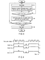
- FIG. 3 is a flowchart for explaining operations of the first and second embodiments;
- FIG. 4 is a timing chart for explaining operations of the first embodiment;
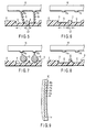
- FIG. 5 shows a state in which four ink droplets are continuously ejected from each nozzle of the inkjet head in each embodiment;
- FIG. 6 shows a state in which ink is accommodated in and applied to each cell of a liquid crystal filter in each embodiment;
- FIG. 7 shows a state in which one large ink droplet is ejected from each nozzle of the inkjet head for reference purposes;
- FIG. 8 shows a state in which the ink is splattered when the one large ink droplet is ejected from each nozzle of the inkjet head;
- FIG. 9 shows a configuration of the inkjet head in the second embodiment;
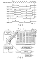
- FIG. 10 is a timing chart for explaining the operation of the second embodiment;
- FIG. 11 shows a configuration of a third embodiment of the invention;
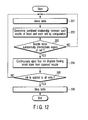
- FIG. 12 a flowchart for explaining the operation of the third embodiment;
- FIG. 13 is a state transition view showing correspondence between each nozzle of a inkjet head and a liquid crystal filter in the third embodiment;
- FIG. 14 is a state transition view continued from FIG. 13;
- FIG. 15 is a state transition view continued from FIG. 14;
- FIG. 16 is a state transition view continued from FIG. 15;
- FIG. 17 is a state transition view continued from FIG. 16; and
- FIG. 18 is a state transition view continued from FIG. 17.
- Referring to the drawings, a first embodiment of the present invention will be described.
- As shown in FIG. 1, a
liquid crystal filter 2 is placed on a table 1 which is movable in a direction of an arrow shown by a wide line. Theliquid crystal filter 2 has pluralconcave cells 3 on an upper surface of a translucent plate-shaped member. Thecells 3 are arrayed in a matrix shape along a moving direction (X-direction) of theliquid crystal filter 2 and along a direction (Y-direction) orthogonal to the moving direction. Each of thecells 3 is formed in a rectangle. The length in a longitudinal direction along the moving direction (X-direction) of theliquid crystal filter 2 is set at L1, and the length in a crosswise direction along the direction (Y-direction) orthogonal to the moving direction of theliquid crystal filter 2 is set at L2. The pitch between theadjacent cells 3 is set at L3 in the direction (Y-direction) orthogonal to the moving direction of theliquid crystal filter 2. - An
inkjet head 10 that can form one pixel by applying a plurality of several ink droplets is provided on the side toward which theliquid crystal filter 2 is moved. Theinkjet head 10 has a long rectangular shape extending in the direction (Y-direction) orthogonal to the moving direction of theliquid crystal filter 2. Theinkjet head 10 is arranged on a moving path of theliquid crystal filter 2 while crossing the moving path.Plural nozzles inkjet head 10. The nozzles are arranged in line with constant intervals along the direction (Y-direction) orthogonal to the moving direction of theliquid crystal filter 2. In consideration of the pitch L3 between thecells 3 on theliquid crystal filter 2, the interval is previously determined so that each nozzle and eachcell 3 faces each other when theliquid crystal filter 2 is moved directly below theinkjet head 10. - The
inkjet head 10 hasoscillators inkjet head 10 distributes red (R), green (G), and blue (B) color inks, which are supplied from anink supply unit 12, among thenozzles nozzles oscillators nozzle 11a when theoscillator 10a is activated, the ink is ejected from thenozzle 11b when theoscillator 10b is activated, and the ink is ejected from thenozzle 11n when theoscillator 10n is activated. - A
head drive unit 13 is provided in order to drive theoscillators inkjet head 10. Thehead drive unit 13 has switches Sa, Sb, ..., and Sn corresponding to theoscillators head drive unit 13 supplies a drive pulse voltage to theoscillators oscillator 10a by turning on the switch Sa, theoscillator 10a repeats short-time operation four times to continuously eject the four ink droplets having small sizes from thenozzle 11a. Similarly, when the four drive pulse voltages are supplied to theoscillator 10a by turning on the switch Sb, theoscillator 10b repeats the short-time operation four times to continuously eject the four ink droplets having the small sizes from thenozzle 11b, and the pixel of one cell is formed. - A
controller 20 controls the whole of the apparatus. Theink supply unit 12, thehead drive unit 13, anoperation unit 21, and atable drive mechanism 22 are connected to thecontroller 20. Thetable drive mechanism 22 moves the table 1 to a position according to a control command from thecontroller 20. - The
controller 20 has the following means (1) and (2): - (1) Means for determining a positional relationship between the
nozzles inkjet head 10 and thecells 3 of theliquid crystal filter 2 by computation through the control of thetable drive mechanism 22. - (2) Control means for continuously ejecting the several (for example, four) ink droplets having small sizes by turning on the switches Sa, Sb, ..., and Sn of the
head drive unit 13 for predetermined time intervals (for example, intervals corresponding to the four drive pulse voltages) based on the computation of the positional relationship. - The, referring to a flowchart of FIG. 3 and a timing chart of FIG. 4, the operation will be described.
- The table 1 is moved toward the side the
inkjet head 10 by the operation of the table drive mechanism 22 (Step 101). According to the movement of the table 1, the positional relationship between thenozzles inkjet head 10 and thecells 3 of theliquid crystal filter 2 is determined by the computation (Step 102). - When the
nozzles inkjet head 10 face thecells 3 in a first line of theliquid crystal filter 2, respectively (YES in Step 103), the switches Sa, Sb, ..., and Sn of thehead drive unit 13 are turned on for the time intervals corresponding to the four drive pulse voltages. Therefore, the four ink droplets having small sizes are continuously ejected from thenozzles - As shown in FIG. 5, the four ink droplets Q having small sizes, which are continuously ejected so that the ink droplets Q are not combined before the ink droplets land on the cell, are thrown into each of the
cells 3 in the first line. At this point, since the thrown ink droplets have small sizes, the ink droplets are not broken by hitting the circumferential portion of thecell 3, but the ink droplets are securely accommodated in and applied to thecell 3. FIG. 6 shows the state in which the ink is applied. - FIG. 7 shows the state in which the one large ink droplet Q is ejected from each nozzle for reference purposes. In this case, since the ejected droplet has the large size, sometimes the ink droplet is broken by hitting the circumferential portion of the
cell 3. As shown in FIG. 8, a part of the broken ink droplet is splattered to adhere to the region between the cell and theadjacent cell 3 or to flow into theadjacent cell 3 to mix with another color ink Q. - According to the first embodiment, the four ink droplets Q having small sizes are continuously ejected from each nozzle. The ink droplets Q are securely accommodated in and applied to the
cell 3 without splattering around the perimeter. Therefore, a decrease in quality is not generated in theliquid crystal filter 2. - When the
nozzles inkjet head 10 face thecells 3 in a second line of theliquid crystal filter 2, respectively (YES in Step 103), the four ink droplets Q having small sizes are continuously ejected from each nozzle again. - When the ink droplets Q are applied to all the
cells 3 in the liquid crystal filter 2 (YES in Step 105), the movement of the table 1 is stopped (Step 106). - A second embodiment of the invention will be described below.
- In manufacturing the
inkjet head 10, sometimes deformation such as warpage is generated in theinkjet head 10. In this case, as shown in FIG. 9, position deviation occurs in thenozzles - When the operator finds the position deviation of each nozzle, data indicating the position deviation of each nozzle is input to the
controller 20 by operating theoperation unit 21. Thecontroller 20 adjusts ejection timing of the ink droplet Q in each nozzle based on the input data. - Referring to a timing chart of FIG. 10, the operation will be described below.
- Since the
nozzles nozzles - The positions of the
nozzles liquid crystal filter 2 from the proper positions on the alternate long and dash line. Therefore, the switches Sc, Sd, and Se are turned on while delayed by one drive voltage pulse rather than the normal timing. Therefore, the four ink droplets Q having small sizes are continuously ejected from each of thenozzles - The position of the
nozzle 11f is slightly deviated toward the moving direction (X-direction) side of theliquid crystal filter 2 from the positions of thenozzles nozzle 11f by two drive voltage pulses rather than the normal timing. - Thus, by adjusting the ejection timing of the ink droplet Q of each nozzle, the ink droplets Q can securely be accommodated in and applied to the
cell 3 irrespective of the position deviation of each nozzle. - Other configurations, operations, and effects are similar to the first embodiment.
- A third embodiment of the invention will be described below.
- As shown in FIG. 11, a
head rotation mechanism 14 is coupled to theinkjet head 10. Thehead rotation mechanism 14 rotates theinkjet head 10 to an angle according to a control command from thecontroller 20. The operator can set the rotation angle of theinkjet head 10 with theoperation unit 21. - When the pitch L3 between the
cells 3 in theliquid crystal filter 2 is small (high-resolution type liquid crystal filter), the operator performs the rotation operation of theinkjet head 10. The rotation operation inclines the line of thenozzles inkjet head 10 by a predetermined angle θ with respect to the direction (Y-direction) orthogonal to the moving direction of theliquid crystal filter 2. - Even if the pitch L3 between the
cells 3 is small, thenozzles cells 3 respectively by inclining the line of thenozzles - The
controller 20 has the following means (11) and (12) as the main function: - (11) Means for determining a positional relationship between the
nozzles inkjet head 10 and thecells 3 of theliquid crystal filter 2 by the computation through the control of thetable drive mechanism 22. - (12) Control means for continuously ejecting the several (for example, four) ink droplets having the small sizes by turning on any one or the plural switches corresponding to the opposite nozzles in the switches Sa, Sb, ..., and Sn of the
head drive unit 13 for predetermined time intervals (for example, intervals corresponding to the four drive pulse voltages) based on the computation of the positional relationship, when any one or the plural nozzles face a substantially intermediate region of thecell 3. - Referring to a flowchart of FIG. 12 and state transition views of FIGS. 13 to 18, the operation will be described below. For the sake of convenience, the small numbers of nozzles and
cells 3 are shown in the state transition views of FIGS. 13 to 18. - The table 1 is moved toward the side the
inkjet head 10 by the action of the table drive mechanism 22 (Step 201). According to the movement of the table 1, the positional relationship between thenozzles inkjet head 10 and thecells 3 of theliquid crystal filter 2 is determined by the computation (Step 202). - As shown in FIGS. 13 to 18, the region of each
cell 3 is apparently divided into ten regions in the longitudinal direction by timing pulse signals generated according to the movement of the table 1. Thetable drive mechanism 22 provides the timing pulse signal to thecontroller 20. Thecontroller 20 recognizes each region divided from eachcell 3 according to the timing pulse signal. Thecontroller 20 recognizes the two regions combining the fifth region and the sixth region as a substantially intermediate region P. - At first, as shown in FIG. 13, the
nozzle 11a faces the substantially intermediate region P of theuppermost cell 3 in the first line (YES in Step 203). At this point, the switch Sa of thehead drive unit 13 is turned on only for the time intervals corresponding to the four drive pulse voltages. Therefore, the four ink droplets Q having small sizes are continuously ejected from thenozzle 11a (Step 204). The ejected four ink droplets Q having small sizes are thrown into thecell 3. The thrown ink droplets are uniformly distributed in the whole region of thecell 3 and applied to thecell 3. FIG. 14 shows the state in which the ink droplets Q are applied by a hatch pattern. - Then, as shown in FIG. 14, the
nozzle 11b faces the substantially intermediate region P of the seconduppermost cell 3 in the first line (YES in Step 203). At this point, the switch Sb of thehead drive unit 13 is turned on only for the time intervals corresponding to the four drive pulse voltages. Therefore, the four ink droplets Q having small sizes are continuously ejected from thenozzle 11b (Step 204). The ejected four ink droplets Q having small sizes are thrown into thecell 3. The thrown ink droplets are uniformly distributed in the whole region of thecell 3 and applied to thecell 3. - Thus, according to the movement of the
liquid crystal filter 2, as shown in FIGS. 15 to 18, the ink droplets Q are sequentially thrown into eachcell 3 of theliquid crystal filter 2. - Particularly, FIGS. 15 to 18 show the state in which the two nozzles face the two substantially intermediate regions P of the
cells 3. In these cases, the four ink droplets Q having small sizes are continuously ejected from each of the two nozzles. The ejected four ink droplets Q having small sizes are thrown into each of the twocells 3. - In the third embodiment, the four ink droplets Q having small sizes are ejected from each nozzle. However, when the
cell 3 has a small area, the number of ink droplets ejected from each nozzle is decreased to three or two. - When the ink droplets Q are applied to all the
cells 3 in the liquid crystal filter 2 (YES in Step 205), the movement of the table 1 is stopped (Step 206). - Other configurations, operations, and effects are similar to the first embodiment. Modification
- The first to third embodiments have the configuration in which the
inkjet head 10 is fixed and theliquid crystal filter 2 is moved. However, it is also possible that theliquid crystal filter 2 is fixed and theinkjet head 10 is moved. - The invention is not effective only in the liquid crystal filter manufacturing apparatus, and is effective in other apparatus.
Claims (15)
- A liquid crystal filter manufacturing apparatus in which a plurality of concave cells (3) are arrayed in an upper surface of a translucent plate-shaped member, the apparatus characterized by comprising:an inkjet head (10) having a plurality of nozzles (11a, 11b, ..., and 11n) to eject coloring ink (R, G, B) to said each cell (3), the inkjet head (10) being moved relative to the liquid crystal filter (2); anda controller (20) which continuously ejects several small ink droplets (Q) from each nozzle (11a, 11b, ..., and 11n) when each nozzle (11a, 11b, ..., and 11n) of the inkjet head (10) faces each cell (3) of the liquid crystal filter (2), so that the ink droplets are not combined together before the ink droplets land on the cell (3) of the crystal filter (2).
- The apparatus according to claim 1, characterized in that the cells (3) of the liquid crystal filter (2) are arrayed in a matrix shape along a relative moving direction between the liquid crystal filter (2) and the inkjet head (10) and along a direction orthogonal to the moving direction.
- The apparatus according to claim 2, characterized in that the nozzles (11a, 11b, ..., and 11n) of the inkjet head (10) are arrayed along the direction orthogonal to the relative moving direction.
- The apparatus according to claim 3, characterized in that the controller (20) has means for adjusting ink (Q) ejection timing of each nozzle (11a, 11b, ..., and 11n) according to position deviation of said each nozzle (11a, 11b, ..., and 11n).
- The apparatus according to claim 2, characterized in that the nozzles (11a, 11b, ..., and 11n) of the inkjet head (10) are arrayed while inclined by a predetermined angle θ with respect to the direction orthogonal to the relative moving direction.
- The apparatus according to claim 5, characterized in that the controller (20) continuously ejects the several ink droplets having the small sizes from any one or the plurality of nozzles (11a, 11b, ..., and 11n) when any one or the plurality of nozzles (11a, 11b, ..., and 11n) of the inkjet head (10) face any one or the plurality of cells (3) of the liquid crystal filter (2).
- The apparatus according to claim 5, characterized in that the controller (20) continuously ejects the several ink (Q) droplets having the small sizes from any one or the plurality of nozzles (11a, 11b, ..., and 11n) when any one or the plurality of nozzles (11a, 11b, ..., and 11n) of the inkjet head (10) face a substantially intermediate region of any one or the plurality of cells (3) of the liquid crystal filter (2).
- A liquid crystal filter manufacturing apparatus in which a plurality of concave cells (3) are arrayed in an upper surface of a translucent plate-shaped member, the apparatus characterized by comprising:an inkjet head (10) having a plurality of nozzles (11a, 11b, ..., and 11n) to eject coloring ink (R, G, B) to said each cell (3), the inkjet head (10) being moved relative to the liquid crystal filter (2); andcontrol means for continuously ejecting several small ink (Q) droplets from each nozzle (11a, 11b, ..., and 11n) when each nozzle (11a, 11b, ..., and 11n) of the inkjet head (10) faces each cell (3) of the liquid crystal filter (2), so that the ink droplets are not combined together before the ink droplets land on the cell (3) of the crystal filter (2).
- The apparatus according to claim 8, characterized in that the cells (3) of the liquid crystal filter (2) are arrayed in a matrix shape along a relative moving direction between the liquid crystal filter (2) and the inkjet head (10) and along a direction orthogonal to the moving direction.
- The apparatus according to claim 9, characterized in that the nozzles (11a, 11b, ..., and 11n) of the inkjet head (10) are arrayed along the direction orthogonal to the relative moving direction.
- The apparatus according to claim 10, characterized in that the control means has means for adjusting ink (Q) ejection timing of each nozzle (11a, 11b, ..., and 11n) according to position deviation of said each nozzle (11a, 11b, ..., and 11n).
- The apparatus according to claim 9, characterized in that the nozzles (11a, 11b, ..., and 11n) of the inkjet head (10) are arrayed while inclined by a predetermined angle θ with respect to the direction orthogonal to the relative moving direction.
- The apparatus according to claim 12, characterized in that the control means continuously ejects the several ink (Q) droplets having the small sizes from any one or the plurality of nozzles (11a, 11b, ..., and 11n) when any one or the plurality of nozzles (11a, 11b, ..., and 11n) of the inkjet head (10) face any one or the plurality of cells (3) of the liquid crystal filter (2).
- The apparatus according to claim 12, characterized in that the control means continuously ejects the several ink (Q) droplets having the small sizes from any one or the plurality of nozzles (11a, 11b, ..., and 11n) when any one or the plurality of nozzles (11a, 11b, ..., and 11n) of the inkjet head (10) face a substantially intermediate region of any one or the plurality of cells (3) of the liquid crystal filter (2).
- A method which controls an inkjet head characterized by comprising:continuously ejecting several small ink droplets from the inkjet head (10), so that the ink droplets are not combine together before the ink droplets land on the surface to be printed.
Applications Claiming Priority (1)
| Application Number | Priority Date | Filing Date | Title |
|---|---|---|---|
| JP2004263561A JP2006078828A (en) | 2004-09-10 | 2004-09-10 | Liquid crystal filter manufacturing equipment |
Publications (2)
| Publication Number | Publication Date |
|---|---|
| EP1634712A2 true EP1634712A2 (en) | 2006-03-15 |
| EP1634712A3 EP1634712A3 (en) | 2007-07-11 |
Family
ID=35351692
Family Applications (1)
| Application Number | Title | Priority Date | Filing Date |
|---|---|---|---|
| EP05018218A Withdrawn EP1634712A3 (en) | 2004-09-10 | 2005-08-23 | Liquid crystal filter manufacturing apparatus having an inkjet head and method for controlling the inkjet head |
Country Status (3)
| Country | Link |
|---|---|
| US (1) | US20060054086A1 (en) |
| EP (1) | EP1634712A3 (en) |
| JP (1) | JP2006078828A (en) |
Families Citing this family (1)
| Publication number | Priority date | Publication date | Assignee | Title |
|---|---|---|---|---|
| KR101212151B1 (en) * | 2005-12-29 | 2012-12-13 | 엘지디스플레이 주식회사 | Method of manufacturing Liquid Crystal Display Device using Patterning Method |
Citations (3)
| Publication number | Priority date | Publication date | Assignee | Title |
|---|---|---|---|---|
| JPH0930664A (en) | 1995-07-19 | 1997-02-04 | Tec Corp | Paper feeder of printing device |
| JP2001108820A (en) | 1995-04-20 | 2001-04-20 | Canon Inc | Method and apparatus for manufacturing color filter, method for manufacturing liquid crystal display, and method for manufacturing apparatus equipped with liquid crystal display |
| JP2002273868A (en) | 2001-01-15 | 2002-09-25 | Seiko Epson Corp | Material discharging device and discharging method, color filter manufacturing device and manufacturing method, liquid crystal device manufacturing device and manufacturing method, EL device manufacturing device and manufacturing method, and electronic equipment manufactured by these methods |
Family Cites Families (11)
| Publication number | Priority date | Publication date | Assignee | Title |
|---|---|---|---|---|
| JP3339724B2 (en) * | 1992-09-29 | 2002-10-28 | 株式会社リコー | Ink jet recording method and apparatus |
| JP2839133B2 (en) * | 1994-03-31 | 1998-12-16 | キヤノン株式会社 | Method and apparatus for manufacturing color filter, method for manufacturing liquid crystal display, and method for manufacturing apparatus equipped with liquid crystal display |
| US5984470A (en) * | 1995-04-20 | 1999-11-16 | Canon Kabushiki Kaisha | Apparatus for producing color filter with alignment error detection |
| JP3832518B2 (en) * | 1995-09-28 | 2006-10-11 | セイコーエプソン株式会社 | Manufacturing method of color filter |
| US6630274B1 (en) * | 1998-12-21 | 2003-10-07 | Seiko Epson Corporation | Color filter and manufacturing method therefor |
| JP3697131B2 (en) * | 2000-02-21 | 2005-09-21 | キヤノン株式会社 | Manufacturing method of color filter, manufacturing apparatus, manufacturing method of display device including color filter, and manufacturing method of device including the display device |
| US6893103B2 (en) * | 2000-10-17 | 2005-05-17 | Seiko Epson Corporation | Ink jet recording apparatus and manufacturing method for functional liquid applied substrate |
| JP4971560B2 (en) * | 2001-08-06 | 2012-07-11 | キヤノン株式会社 | Inkjet recording apparatus, head unit, and color filter manufacturing apparatus |
| JP2003159786A (en) * | 2001-11-28 | 2003-06-03 | Seiko Epson Corp | Discharge method and apparatus, electro-optical apparatus, method for manufacturing the same and apparatus for manufacturing the same, color filter, method for manufacturing the same and apparatus for manufacturing the same, device having base material, method for manufacturing the same, and apparatus for manufacturing the same |
| JP2003182071A (en) * | 2001-12-17 | 2003-07-03 | Seiko Epson Corp | INK JET HEAD AND ITS MANUFACTURING METHOD, INK JET RECORDING DEVICE AND ITS MANUFACTURING METHOD, COLOR FILTER MANUFACTURING DEVICE AND ITS MANUFACTURING METHOD, AND ELECTROLUMINATED SUBSTRATE MANUFACTURING DEVICE AND ITS MANUFACTURING METHOD |
| JP2004029390A (en) * | 2002-06-26 | 2004-01-29 | Matsushita Electric Ind Co Ltd | Liquid filling method and liquid crystal display element |
-
2004
- 2004-09-10 JP JP2004263561A patent/JP2006078828A/en not_active Abandoned
-
2005
- 2005-08-23 EP EP05018218A patent/EP1634712A3/en not_active Withdrawn
- 2005-09-09 US US11/221,980 patent/US20060054086A1/en not_active Abandoned
Patent Citations (3)
| Publication number | Priority date | Publication date | Assignee | Title |
|---|---|---|---|---|
| JP2001108820A (en) | 1995-04-20 | 2001-04-20 | Canon Inc | Method and apparatus for manufacturing color filter, method for manufacturing liquid crystal display, and method for manufacturing apparatus equipped with liquid crystal display |
| JPH0930664A (en) | 1995-07-19 | 1997-02-04 | Tec Corp | Paper feeder of printing device |
| JP2002273868A (en) | 2001-01-15 | 2002-09-25 | Seiko Epson Corp | Material discharging device and discharging method, color filter manufacturing device and manufacturing method, liquid crystal device manufacturing device and manufacturing method, EL device manufacturing device and manufacturing method, and electronic equipment manufactured by these methods |
Also Published As
| Publication number | Publication date |
|---|---|
| EP1634712A3 (en) | 2007-07-11 |
| US20060054086A1 (en) | 2006-03-16 |
| JP2006078828A (en) | 2006-03-23 |
Similar Documents
| Publication | Publication Date | Title |
|---|---|---|
| JP2002103597A (en) | Printer and printer head | |
| KR20140135606A (en) | Ink jet apparatus and head layout method for ink jet apparatus | |
| JP4437805B2 (en) | Ink ejection apparatus and ink ejection control method | |
| JP4692551B2 (en) | Liquid material discharge apparatus and liquid material discharge method | |
| JP4692552B2 (en) | Liquid material discharge apparatus and liquid material discharge method | |
| WO2003045696A1 (en) | Liquid discharging device, and liquid discharging method | |
| EP1642724A3 (en) | A droplet ejection apparatus, a method of using the same | |
| JP2007136330A (en) | Ink ejection apparatus and ink ejection method | |
| KR100786995B1 (en) | Inkjet printing equipment | |
| US20060054086A1 (en) | Liquid crystal filter manufacturing apparatus and method for controlling the inkjet head | |
| US20090244136A1 (en) | Drawing method, inkjet head, drawing apparatus, method for fabricating printed wiring board and method for manufacturing color filter | |
| US8430479B2 (en) | Liquid droplet jetting apparatus | |
| CN113771494B (en) | Inkjet printing device and printing method | |
| JP2009066882A (en) | Method for preparing chart for adjusting nozzle position, method for adjusting nozzle position, and image forming apparatus | |
| JP4525758B2 (en) | Liquid material discharge device | |
| JP2002365424A (en) | Method and apparatus for manufacturing color filter | |
| TWI398358B (en) | Color filter manufacturing method and device thereof | |
| KR100733059B1 (en) | Droplet discharge method, electro-optical device, and electronic device | |
| JP2016185606A (en) | Liquid discharge head and liquid discharge device | |
| JP4710258B2 (en) | Color filter forming method and forming apparatus | |
| JP7306079B2 (en) | Liquid ejector | |
| KR20070081768A (en) | Pattern forming method, droplet ejection device, electro-optical device and liquid crystal display device | |
| JP4765489B2 (en) | Image forming method and image forming apparatus | |
| JP5011772B2 (en) | Functional droplet discharge method and color filter manufacturing method | |
| JP2007029830A (en) | Inkjet coating method and apparatus |
Legal Events
| Date | Code | Title | Description |
|---|---|---|---|
| PUAI | Public reference made under article 153(3) epc to a published international application that has entered the european phase |
Free format text: ORIGINAL CODE: 0009012 |
|
| 17P | Request for examination filed |
Effective date: 20050823 |
|
| AK | Designated contracting states |
Kind code of ref document: A2 Designated state(s): AT BE BG CH CY CZ DE DK EE ES FI FR GB GR HU IE IS IT LI LT LU LV MC NL PL PT RO SE SI SK TR |
|
| AX | Request for extension of the european patent |
Extension state: AL BA HR MK YU |
|
| PUAL | Search report despatched |
Free format text: ORIGINAL CODE: 0009013 |
|
| AK | Designated contracting states |
Kind code of ref document: A3 Designated state(s): AT BE BG CH CY CZ DE DK EE ES FI FR GB GR HU IE IS IT LI LT LU LV MC NL PL PT RO SE SI SK TR |
|
| AX | Request for extension of the european patent |
Extension state: AL BA HR MK YU |
|
| AKX | Designation fees paid |
Designated state(s): DE FR GB |
|
| 17Q | First examination report despatched |
Effective date: 20080625 |
|
| STAA | Information on the status of an ep patent application or granted ep patent |
Free format text: STATUS: THE APPLICATION IS DEEMED TO BE WITHDRAWN |
|
| 18D | Application deemed to be withdrawn |
Effective date: 20091006 |