EP1634075B1 - Elektronische Vorrichtung zur Kommunikation mit lebenden Zellen - Google Patents
Elektronische Vorrichtung zur Kommunikation mit lebenden Zellen Download PDFInfo
- Publication number
- EP1634075B1 EP1634075B1 EP04736573.9A EP04736573A EP1634075B1 EP 1634075 B1 EP1634075 B1 EP 1634075B1 EP 04736573 A EP04736573 A EP 04736573A EP 1634075 B1 EP1634075 B1 EP 1634075B1
- Authority
- EP
- European Patent Office
- Prior art keywords
- electrode
- substrate
- micronail
- molecules
- cell
- Prior art date
- Legal status (The legal status is an assumption and is not a legal conclusion. Google has not performed a legal analysis and makes no representation as to the accuracy of the status listed.)
- Not-in-force
Links
- 238000004891 communication Methods 0.000 title claims description 16
- 210000004027 cell Anatomy 0.000 claims description 114
- 210000000170 cell membrane Anatomy 0.000 claims description 53
- 239000000758 substrate Substances 0.000 claims description 53
- 102000004190 Enzymes Human genes 0.000 claims description 38
- 108090000790 Enzymes Proteins 0.000 claims description 38
- 239000010931 gold Substances 0.000 claims description 30
- 239000010410 layer Substances 0.000 claims description 28
- PCHJSUWPFVWCPO-UHFFFAOYSA-N gold Chemical compound [Au] PCHJSUWPFVWCPO-UHFFFAOYSA-N 0.000 claims description 27
- 229910052737 gold Inorganic materials 0.000 claims description 27
- 102000005962 receptors Human genes 0.000 claims description 24
- 108020003175 receptors Proteins 0.000 claims description 24
- 238000000034 method Methods 0.000 claims description 23
- 102000004169 proteins and genes Human genes 0.000 claims description 19
- 108090000623 proteins and genes Proteins 0.000 claims description 19
- 230000003301 hydrolyzing effect Effects 0.000 claims description 17
- 239000012528 membrane Substances 0.000 claims description 17
- 239000002356 single layer Substances 0.000 claims description 15
- 102000010834 Extracellular Matrix Proteins Human genes 0.000 claims description 14
- 108010037362 Extracellular Matrix Proteins Proteins 0.000 claims description 14
- 230000027455 binding Effects 0.000 claims description 13
- 210000002744 extracellular matrix Anatomy 0.000 claims description 13
- 108090000765 processed proteins & peptides Proteins 0.000 claims description 13
- 230000001737 promoting effect Effects 0.000 claims description 13
- 229910052751 metal Inorganic materials 0.000 claims description 12
- 239000002184 metal Substances 0.000 claims description 12
- 230000001413 cellular effect Effects 0.000 claims description 10
- 239000000463 material Substances 0.000 claims description 10
- 102000004196 processed proteins & peptides Human genes 0.000 claims description 10
- 230000015556 catabolic process Effects 0.000 claims description 8
- 238000006731 degradation reaction Methods 0.000 claims description 8
- 239000012634 fragment Substances 0.000 claims description 8
- 239000002858 neurotransmitter agent Substances 0.000 claims description 8
- QZAYGJVTTNCVMB-UHFFFAOYSA-N serotonin Chemical compound C1=C(O)C=C2C(CCN)=CNC2=C1 QZAYGJVTTNCVMB-UHFFFAOYSA-N 0.000 claims description 8
- OIPILFWXSMYKGL-UHFFFAOYSA-N acetylcholine Chemical compound CC(=O)OCC[N+](C)(C)C OIPILFWXSMYKGL-UHFFFAOYSA-N 0.000 claims description 7
- 229960004373 acetylcholine Drugs 0.000 claims description 7
- 150000002500 ions Chemical class 0.000 claims description 7
- 229910021420 polycrystalline silicon Inorganic materials 0.000 claims description 7
- VYPSYNLAJGMNEJ-UHFFFAOYSA-N Silicium dioxide Chemical compound O=[Si]=O VYPSYNLAJGMNEJ-UHFFFAOYSA-N 0.000 claims description 6
- 238000001514 detection method Methods 0.000 claims description 6
- 239000003446 ligand Substances 0.000 claims description 6
- BASFCYQUMIYNBI-UHFFFAOYSA-N platinum Chemical compound [Pt] BASFCYQUMIYNBI-UHFFFAOYSA-N 0.000 claims description 6
- 229920001467 poly(styrenesulfonates) Polymers 0.000 claims description 6
- 125000006850 spacer group Chemical group 0.000 claims description 6
- 229910052581 Si3N4 Inorganic materials 0.000 claims description 5
- 230000008859 change Effects 0.000 claims description 5
- 102000006240 membrane receptors Human genes 0.000 claims description 5
- 108020004084 membrane receptors Proteins 0.000 claims description 5
- 230000003248 secreting effect Effects 0.000 claims description 5
- HQVNEWCFYHHQES-UHFFFAOYSA-N silicon nitride Chemical compound N12[Si]34N5[Si]62N3[Si]51N64 HQVNEWCFYHHQES-UHFFFAOYSA-N 0.000 claims description 5
- WFKWXMTUELFFGS-UHFFFAOYSA-N tungsten Chemical compound [W] WFKWXMTUELFFGS-UHFFFAOYSA-N 0.000 claims description 5
- 229910052721 tungsten Inorganic materials 0.000 claims description 5
- 239000010937 tungsten Substances 0.000 claims description 5
- 238000006243 chemical reaction Methods 0.000 claims description 4
- 230000005669 field effect Effects 0.000 claims description 4
- 229960003692 gamma aminobutyric acid Drugs 0.000 claims description 4
- BTCSSZJGUNDROE-UHFFFAOYSA-N gamma-aminobutyric acid Chemical compound NCCCC(O)=O BTCSSZJGUNDROE-UHFFFAOYSA-N 0.000 claims description 4
- 150000004676 glycans Chemical class 0.000 claims description 4
- 102000006495 integrins Human genes 0.000 claims description 4
- 108010044426 integrins Proteins 0.000 claims description 4
- 150000002739 metals Chemical class 0.000 claims description 4
- 229920000767 polyaniline Polymers 0.000 claims description 4
- 229940076279 serotonin Drugs 0.000 claims description 4
- RYGMFSIKBFXOCR-UHFFFAOYSA-N Copper Chemical compound [Cu] RYGMFSIKBFXOCR-UHFFFAOYSA-N 0.000 claims description 3
- WHUUTDBJXJRKMK-VKHMYHEASA-N L-glutamic acid Chemical compound OC(=O)[C@@H](N)CCC(O)=O WHUUTDBJXJRKMK-VKHMYHEASA-N 0.000 claims description 3
- 108090001090 Lectins Proteins 0.000 claims description 3
- 102000004856 Lectins Human genes 0.000 claims description 3
- 108091005804 Peptidases Proteins 0.000 claims description 3
- 102000035195 Peptidases Human genes 0.000 claims description 3
- 108010039918 Polylysine Proteins 0.000 claims description 3
- BQCADISMDOOEFD-UHFFFAOYSA-N Silver Chemical compound [Ag] BQCADISMDOOEFD-UHFFFAOYSA-N 0.000 claims description 3
- 229910052782 aluminium Inorganic materials 0.000 claims description 3
- XAGFODPZIPBFFR-UHFFFAOYSA-N aluminium Chemical compound [Al] XAGFODPZIPBFFR-UHFFFAOYSA-N 0.000 claims description 3
- 229910052802 copper Inorganic materials 0.000 claims description 3
- 239000010949 copper Substances 0.000 claims description 3
- 125000000524 functional group Chemical group 0.000 claims description 3
- 229940049906 glutamate Drugs 0.000 claims description 3
- 229930195712 glutamate Natural products 0.000 claims description 3
- 239000002523 lectin Substances 0.000 claims description 3
- 230000035515 penetration Effects 0.000 claims description 3
- 229910052697 platinum Inorganic materials 0.000 claims description 3
- 229920000656 polylysine Polymers 0.000 claims description 3
- 229920001282 polysaccharide Polymers 0.000 claims description 3
- 239000005017 polysaccharide Substances 0.000 claims description 3
- 229960002796 polystyrene sulfonate Drugs 0.000 claims description 3
- 239000011970 polystyrene sulfonate Substances 0.000 claims description 3
- 235000019833 protease Nutrition 0.000 claims description 3
- 229910052709 silver Inorganic materials 0.000 claims description 3
- 239000004332 silver Substances 0.000 claims description 3
- 108090000371 Esterases Proteins 0.000 claims description 2
- 102000003886 Glycoproteins Human genes 0.000 claims description 2
- 108090000288 Glycoproteins Proteins 0.000 claims description 2
- 125000001931 aliphatic group Chemical group 0.000 claims description 2
- 229910045601 alloy Inorganic materials 0.000 claims description 2
- 239000000956 alloy Substances 0.000 claims description 2
- 125000003118 aryl group Chemical group 0.000 claims description 2
- 210000000805 cytoplasm Anatomy 0.000 claims description 2
- 238000005530 etching Methods 0.000 claims description 2
- 125000001072 heteroaryl group Chemical group 0.000 claims description 2
- 238000001459 lithography Methods 0.000 claims description 2
- TWNQGVIAIRXVLR-UHFFFAOYSA-N oxo(oxoalumanyloxy)alumane Chemical compound O=[Al]O[Al]=O TWNQGVIAIRXVLR-UHFFFAOYSA-N 0.000 claims 2
- 229910052814 silicon oxide Inorganic materials 0.000 claims 2
- 102000004127 Cytokines Human genes 0.000 claims 1
- 108090000695 Cytokines Proteins 0.000 claims 1
- 102000016611 Proteoglycans Human genes 0.000 claims 1
- 108010067787 Proteoglycans Proteins 0.000 claims 1
- 125000003275 alpha amino acid group Chemical group 0.000 claims 1
- 150000001450 anions Chemical group 0.000 claims 1
- 239000003102 growth factor Substances 0.000 claims 1
- AMGQUBHHOARCQH-UHFFFAOYSA-N indium;oxotin Chemical compound [In].[Sn]=O AMGQUBHHOARCQH-UHFFFAOYSA-N 0.000 claims 1
- 230000000955 neuroendocrine Effects 0.000 claims 1
- BPUBBGLMJRNUCC-UHFFFAOYSA-N oxygen(2-);tantalum(5+) Chemical compound [O-2].[O-2].[O-2].[O-2].[O-2].[Ta+5].[Ta+5] BPUBBGLMJRNUCC-UHFFFAOYSA-N 0.000 claims 1
- 210000002569 neuron Anatomy 0.000 description 55
- 230000008782 phagocytosis Effects 0.000 description 34
- 206010057249 Phagocytosis Diseases 0.000 description 33
- 230000008878 coupling Effects 0.000 description 28
- 238000010168 coupling process Methods 0.000 description 28
- 238000005859 coupling reaction Methods 0.000 description 28
- 239000002245 particle Substances 0.000 description 26
- 239000000126 substance Substances 0.000 description 25
- 238000007667 floating Methods 0.000 description 18
- 230000012202 endocytosis Effects 0.000 description 13
- 230000008569 process Effects 0.000 description 13
- 230000015572 biosynthetic process Effects 0.000 description 11
- 238000004873 anchoring Methods 0.000 description 10
- 230000011664 signaling Effects 0.000 description 10
- 230000003993 interaction Effects 0.000 description 9
- 150000004767 nitrides Chemical group 0.000 description 9
- 210000000225 synapse Anatomy 0.000 description 9
- 241000587161 Gomphocarpus Species 0.000 description 8
- -1 poly(lactic-acid) Polymers 0.000 description 8
- 241000237967 Aplysia Species 0.000 description 7
- 239000011324 bead Substances 0.000 description 7
- 230000006698 induction Effects 0.000 description 7
- 239000013545 self-assembled monolayer Substances 0.000 description 7
- 238000010276 construction Methods 0.000 description 6
- 230000001159 endocytotic effect Effects 0.000 description 6
- 238000005516 engineering process Methods 0.000 description 6
- 230000036961 partial effect Effects 0.000 description 6
- 238000013459 approach Methods 0.000 description 5
- 238000002474 experimental method Methods 0.000 description 5
- 230000002399 phagocytotic effect Effects 0.000 description 5
- 125000002521 alkyl halide group Chemical group 0.000 description 4
- 230000008901 benefit Effects 0.000 description 4
- 238000012412 chemical coupling Methods 0.000 description 4
- 238000011161 development Methods 0.000 description 4
- 230000018109 developmental process Effects 0.000 description 4
- 238000000635 electron micrograph Methods 0.000 description 4
- 230000007246 mechanism Effects 0.000 description 4
- 210000003205 muscle Anatomy 0.000 description 4
- 230000001537 neural effect Effects 0.000 description 4
- 229920000747 poly(lactic acid) Polymers 0.000 description 4
- 230000035945 sensitivity Effects 0.000 description 4
- 150000001720 carbohydrates Chemical class 0.000 description 3
- 230000007248 cellular mechanism Effects 0.000 description 3
- 239000003795 chemical substances by application Substances 0.000 description 3
- 210000002314 coated vesicle Anatomy 0.000 description 3
- 239000011248 coating agent Substances 0.000 description 3
- 238000000576 coating method Methods 0.000 description 3
- 230000005684 electric field Effects 0.000 description 3
- 210000004907 gland Anatomy 0.000 description 3
- 239000011521 glass Substances 0.000 description 3
- 229920002674 hyaluronan Polymers 0.000 description 3
- 230000007062 hydrolysis Effects 0.000 description 3
- 238000006460 hydrolysis reaction Methods 0.000 description 3
- 230000000670 limiting effect Effects 0.000 description 3
- 150000002632 lipids Chemical class 0.000 description 3
- 230000033001 locomotion Effects 0.000 description 3
- 210000003632 microfilament Anatomy 0.000 description 3
- 230000004048 modification Effects 0.000 description 3
- 238000012986 modification Methods 0.000 description 3
- 230000008884 pinocytosis Effects 0.000 description 3
- 229920002223 polystyrene Polymers 0.000 description 3
- 102000016359 Fibronectins Human genes 0.000 description 2
- 108010067306 Fibronectins Proteins 0.000 description 2
- 108010001336 Horseradish Peroxidase Proteins 0.000 description 2
- HRNLUBSXIHFDHP-UHFFFAOYSA-N N-(2-aminophenyl)-4-[[[4-(3-pyridinyl)-2-pyrimidinyl]amino]methyl]benzamide Chemical compound NC1=CC=CC=C1NC(=O)C(C=C1)=CC=C1CNC1=NC=CC(C=2C=NC=CC=2)=N1 HRNLUBSXIHFDHP-UHFFFAOYSA-N 0.000 description 2
- 208000028389 Nerve injury Diseases 0.000 description 2
- 102000005348 Neuraminidase Human genes 0.000 description 2
- 108010006232 Neuraminidase Proteins 0.000 description 2
- 239000004793 Polystyrene Substances 0.000 description 2
- 102000003970 Vinculin Human genes 0.000 description 2
- 108090000384 Vinculin Proteins 0.000 description 2
- 230000004913 activation Effects 0.000 description 2
- 150000001412 amines Chemical group 0.000 description 2
- 150000001413 amino acids Chemical class 0.000 description 2
- ROOXNKNUYICQNP-UHFFFAOYSA-N ammonium persulfate Chemical compound [NH4+].[NH4+].[O-]S(=O)(=O)OOS([O-])(=O)=O ROOXNKNUYICQNP-UHFFFAOYSA-N 0.000 description 2
- SQVRNKJHWKZAKO-UHFFFAOYSA-N beta-N-Acetyl-D-neuraminic acid Natural products CC(=O)NC1C(O)CC(O)(C(O)=O)OC1C(O)C(O)CO SQVRNKJHWKZAKO-UHFFFAOYSA-N 0.000 description 2
- 230000021164 cell adhesion Effects 0.000 description 2
- 238000001311 chemical methods and process Methods 0.000 description 2
- 238000004140 cleaning Methods 0.000 description 2
- 229910052681 coesite Inorganic materials 0.000 description 2
- 239000007822 coupling agent Substances 0.000 description 2
- 229910052906 cristobalite Inorganic materials 0.000 description 2
- 210000004748 cultured cell Anatomy 0.000 description 2
- 230000003436 cytoskeletal effect Effects 0.000 description 2
- 230000006378 damage Effects 0.000 description 2
- 230000000593 degrading effect Effects 0.000 description 2
- 238000013461 design Methods 0.000 description 2
- 230000000694 effects Effects 0.000 description 2
- 230000005611 electricity Effects 0.000 description 2
- 238000007306 functionalization reaction Methods 0.000 description 2
- KIUKXJAPPMFGSW-MNSSHETKSA-N hyaluronan Chemical compound CC(=O)N[C@H]1[C@H](O)O[C@H](CO)[C@@H](O)C1O[C@H]1[C@H](O)[C@@H](O)[C@H](O[C@H]2[C@@H](C(O[C@H]3[C@@H]([C@@H](O)[C@H](O)[C@H](O3)C(O)=O)O)[C@H](O)[C@@H](CO)O2)NC(C)=O)[C@@H](C(O)=O)O1 KIUKXJAPPMFGSW-MNSSHETKSA-N 0.000 description 2
- 229940099552 hyaluronan Drugs 0.000 description 2
- 230000002209 hydrophobic effect Effects 0.000 description 2
- 230000003100 immobilizing effect Effects 0.000 description 2
- 238000004519 manufacturing process Methods 0.000 description 2
- 239000000178 monomer Substances 0.000 description 2
- 210000000663 muscle cell Anatomy 0.000 description 2
- 210000005036 nerve Anatomy 0.000 description 2
- 230000008764 nerve damage Effects 0.000 description 2
- 210000000653 nervous system Anatomy 0.000 description 2
- 210000001328 optic nerve Anatomy 0.000 description 2
- 230000003647 oxidation Effects 0.000 description 2
- 238000007254 oxidation reaction Methods 0.000 description 2
- 230000006461 physiological response Effects 0.000 description 2
- 238000006116 polymerization reaction Methods 0.000 description 2
- 229920005591 polysilicon Polymers 0.000 description 2
- 230000001242 postsynaptic effect Effects 0.000 description 2
- 230000003518 presynaptic effect Effects 0.000 description 2
- 238000011160 research Methods 0.000 description 2
- 230000002207 retinal effect Effects 0.000 description 2
- 238000001338 self-assembly Methods 0.000 description 2
- SQVRNKJHWKZAKO-OQPLDHBCSA-N sialic acid Chemical compound CC(=O)N[C@@H]1[C@@H](O)C[C@@](O)(C(O)=O)OC1[C@H](O)[C@H](O)CO SQVRNKJHWKZAKO-OQPLDHBCSA-N 0.000 description 2
- 239000000377 silicon dioxide Substances 0.000 description 2
- 238000001179 sorption measurement Methods 0.000 description 2
- 230000002269 spontaneous effect Effects 0.000 description 2
- 230000004936 stimulating effect Effects 0.000 description 2
- 230000000638 stimulation Effects 0.000 description 2
- 229910052682 stishovite Inorganic materials 0.000 description 2
- 230000009747 swallowing Effects 0.000 description 2
- 230000005945 translocation Effects 0.000 description 2
- 229910052905 tridymite Inorganic materials 0.000 description 2
- 210000003934 vacuole Anatomy 0.000 description 2
- KIUKXJAPPMFGSW-DNGZLQJQSA-N (2S,3S,4S,5R,6R)-6-[(2S,3R,4R,5S,6R)-3-Acetamido-2-[(2S,3S,4R,5R,6R)-6-[(2R,3R,4R,5S,6R)-3-acetamido-2,5-dihydroxy-6-(hydroxymethyl)oxan-4-yl]oxy-2-carboxy-4,5-dihydroxyoxan-3-yl]oxy-5-hydroxy-6-(hydroxymethyl)oxan-4-yl]oxy-3,4,5-trihydroxyoxane-2-carboxylic acid Chemical compound CC(=O)N[C@H]1[C@H](O)O[C@H](CO)[C@@H](O)[C@@H]1O[C@H]1[C@H](O)[C@@H](O)[C@H](O[C@H]2[C@@H]([C@@H](O[C@H]3[C@@H]([C@@H](O)[C@H](O)[C@H](O3)C(O)=O)O)[C@H](O)[C@@H](CO)O2)NC(C)=O)[C@@H](C(O)=O)O1 KIUKXJAPPMFGSW-DNGZLQJQSA-N 0.000 description 1
- MXNRLFUSFKVQSK-UHFFFAOYSA-N 2-Amino-6-(trimethylazaniumyl)hexanoate Chemical compound C[N+](C)(C)CCCCC(N)C([O-])=O MXNRLFUSFKVQSK-UHFFFAOYSA-N 0.000 description 1
- QECCPJFWTJFGRA-VYFHOAEYSA-L 2-acetyloxyethyl(trimethyl)azanium (2S)-2-aminopentanedioate Chemical compound N[C@@H](CCC(=O)[O-])C(=O)[O-].C(C)(=O)OCC[N+](C)(C)C.C(C)(=O)OCC[N+](C)(C)C QECCPJFWTJFGRA-VYFHOAEYSA-L 0.000 description 1
- UUNGBOQAZQUJMZ-UHFFFAOYSA-N 3-bromopropyl(trichloro)silane Chemical compound Cl[Si](Cl)(Cl)CCCBr UUNGBOQAZQUJMZ-UHFFFAOYSA-N 0.000 description 1
- WCDSVWRUXWCYFN-UHFFFAOYSA-N 4-aminobenzenethiol Chemical compound NC1=CC=C(S)C=C1 WCDSVWRUXWCYFN-UHFFFAOYSA-N 0.000 description 1
- 241001609368 Acamptopappus Species 0.000 description 1
- 102000004373 Actin-related protein 2 Human genes 0.000 description 1
- 108090000963 Actin-related protein 2 Proteins 0.000 description 1
- 102000005367 Carboxypeptidases Human genes 0.000 description 1
- 108010006303 Carboxypeptidases Proteins 0.000 description 1
- 102000000496 Carboxypeptidases A Human genes 0.000 description 1
- 108010080937 Carboxypeptidases A Proteins 0.000 description 1
- 102000029816 Collagenase Human genes 0.000 description 1
- 108060005980 Collagenase Proteins 0.000 description 1
- KDXKERNSBIXSRK-RXMQYKEDSA-N D-lysine Chemical compound NCCCC[C@@H](N)C(O)=O KDXKERNSBIXSRK-RXMQYKEDSA-N 0.000 description 1
- 108050001049 Extracellular proteins Proteins 0.000 description 1
- 102000009109 Fc receptors Human genes 0.000 description 1
- 108010087819 Fc receptors Proteins 0.000 description 1
- 102000001974 Hyaluronidases Human genes 0.000 description 1
- 108050009363 Hyaluronidases Proteins 0.000 description 1
- 108010058683 Immobilized Proteins Proteins 0.000 description 1
- 108060003951 Immunoglobulin Proteins 0.000 description 1
- 108090001060 Lipase Proteins 0.000 description 1
- 102000004882 Lipase Human genes 0.000 description 1
- 239000004367 Lipase Substances 0.000 description 1
- 108010031099 Mannose Receptor Proteins 0.000 description 1
- 102000012750 Membrane Glycoproteins Human genes 0.000 description 1
- 108010090054 Membrane Glycoproteins Proteins 0.000 description 1
- 102000003505 Myosin Human genes 0.000 description 1
- 108060008487 Myosin Proteins 0.000 description 1
- 102000018546 Paxillin Human genes 0.000 description 1
- ACNHBCIZLNNLRS-UHFFFAOYSA-N Paxilline 1 Natural products N1C2=CC=CC=C2C2=C1C1(C)C3(C)CCC4OC(C(C)(O)C)C(=O)C=C4C3(O)CCC1C2 ACNHBCIZLNNLRS-UHFFFAOYSA-N 0.000 description 1
- 241000312117 Phago Species 0.000 description 1
- 108010064785 Phospholipases Proteins 0.000 description 1
- 102000015439 Phospholipases Human genes 0.000 description 1
- 102000006463 Talin Human genes 0.000 description 1
- 108010083809 Talin Proteins 0.000 description 1
- 108700031954 Tgfb1i1/Leupaxin/TGFB1I1 Proteins 0.000 description 1
- 102000000591 Tight Junction Proteins Human genes 0.000 description 1
- 108010002321 Tight Junction Proteins Proteins 0.000 description 1
- 241000251539 Vertebrata <Metazoa> Species 0.000 description 1
- 208000027418 Wounds and injury Diseases 0.000 description 1
- 230000009471 action Effects 0.000 description 1
- 229940024606 amino acid Drugs 0.000 description 1
- 229910001870 ammonium persulfate Inorganic materials 0.000 description 1
- 235000019395 ammonium persulphate Nutrition 0.000 description 1
- 239000012491 analyte Substances 0.000 description 1
- 238000004458 analytical method Methods 0.000 description 1
- 229940009098 aspartate Drugs 0.000 description 1
- 238000000089 atomic force micrograph Methods 0.000 description 1
- 210000003050 axon Anatomy 0.000 description 1
- 230000000975 bioactive effect Effects 0.000 description 1
- 230000004071 biological effect Effects 0.000 description 1
- 210000004556 brain Anatomy 0.000 description 1
- 210000004899 c-terminal region Anatomy 0.000 description 1
- 239000000969 carrier Substances 0.000 description 1
- 210000005056 cell body Anatomy 0.000 description 1
- 230000009087 cell motility Effects 0.000 description 1
- 230000033077 cellular process Effects 0.000 description 1
- 238000004587 chromatography analysis Methods 0.000 description 1
- 230000000295 complement effect Effects 0.000 description 1
- 102000006834 complement receptors Human genes 0.000 description 1
- 108010047295 complement receptors Proteins 0.000 description 1
- 238000009833 condensation Methods 0.000 description 1
- 230000005494 condensation Effects 0.000 description 1
- 239000002322 conducting polymer Substances 0.000 description 1
- 229920001940 conductive polymer Polymers 0.000 description 1
- 239000004020 conductor Substances 0.000 description 1
- JVHIPYJQMFNCEK-UHFFFAOYSA-N cytochalasin Natural products N1C(=O)C2(C(C=CC(C)CC(C)CC=C3)OC(C)=O)C3C(O)C(=C)C(C)C2C1CC1=CC=CC=C1 JVHIPYJQMFNCEK-UHFFFAOYSA-N 0.000 description 1
- ZMAODHOXRBLOQO-UHFFFAOYSA-N cytochalasin-A Natural products N1C(=O)C23OC(=O)C=CC(=O)CCCC(C)CC=CC3C(O)C(=C)C(C)C2C1CC1=CC=CC=C1 ZMAODHOXRBLOQO-UHFFFAOYSA-N 0.000 description 1
- 210000000172 cytosol Anatomy 0.000 description 1
- 230000001086 cytosolic effect Effects 0.000 description 1
- 238000005034 decoration Methods 0.000 description 1
- 230000003247 decreasing effect Effects 0.000 description 1
- 230000036425 denaturation Effects 0.000 description 1
- 238000004925 denaturation Methods 0.000 description 1
- 210000001787 dendrite Anatomy 0.000 description 1
- 230000001419 dependent effect Effects 0.000 description 1
- 230000008021 deposition Effects 0.000 description 1
- 230000004069 differentiation Effects 0.000 description 1
- 230000003292 diminished effect Effects 0.000 description 1
- KPUWHANPEXNPJT-UHFFFAOYSA-N disiloxane Chemical class [SiH3]O[SiH3] KPUWHANPEXNPJT-UHFFFAOYSA-N 0.000 description 1
- 229940079593 drug Drugs 0.000 description 1
- 239000003814 drug Substances 0.000 description 1
- 239000003792 electrolyte Substances 0.000 description 1
- 238000001493 electron microscopy Methods 0.000 description 1
- 238000009713 electroplating Methods 0.000 description 1
- 230000008030 elimination Effects 0.000 description 1
- 238000003379 elimination reaction Methods 0.000 description 1
- 230000008290 endocytic mechanism Effects 0.000 description 1
- 230000002255 enzymatic effect Effects 0.000 description 1
- 230000007071 enzymatic hydrolysis Effects 0.000 description 1
- 238000006047 enzymatic hydrolysis reaction Methods 0.000 description 1
- 150000002148 esters Chemical class 0.000 description 1
- 235000013305 food Nutrition 0.000 description 1
- 230000006870 function Effects 0.000 description 1
- 230000002068 genetic effect Effects 0.000 description 1
- 150000002343 gold Chemical class 0.000 description 1
- 229960003160 hyaluronic acid Drugs 0.000 description 1
- 125000002887 hydroxy group Chemical group [H]O* 0.000 description 1
- 238000003384 imaging method Methods 0.000 description 1
- 102000018358 immunoglobulin Human genes 0.000 description 1
- 229940072221 immunoglobulins Drugs 0.000 description 1
- 238000001727 in vivo Methods 0.000 description 1
- 208000014674 injury Diseases 0.000 description 1
- ZFSLODLOARCGLH-UHFFFAOYSA-N isocyanuric acid Chemical compound OC1=NC(O)=NC(O)=N1 ZFSLODLOARCGLH-UHFFFAOYSA-N 0.000 description 1
- 235000019421 lipase Nutrition 0.000 description 1
- 210000002540 macrophage Anatomy 0.000 description 1
- 230000001404 mediated effect Effects 0.000 description 1
- 238000001000 micrograph Methods 0.000 description 1
- 230000009149 molecular binding Effects 0.000 description 1
- 238000005442 molecular electronic Methods 0.000 description 1
- 230000009456 molecular mechanism Effects 0.000 description 1
- 239000002105 nanoparticle Substances 0.000 description 1
- 210000000440 neutrophil Anatomy 0.000 description 1
- 229910052755 nonmetal Inorganic materials 0.000 description 1
- ACNHBCIZLNNLRS-UBGQALKQSA-N paxilline Chemical compound N1C2=CC=CC=C2C2=C1[C@]1(C)[C@@]3(C)CC[C@@H]4O[C@H](C(C)(O)C)C(=O)C=C4[C@]3(O)CC[C@H]1C2 ACNHBCIZLNNLRS-UBGQALKQSA-N 0.000 description 1
- PAYRUJLWNCNPSJ-UHFFFAOYSA-O phenylazanium Chemical compound [NH3+]C1=CC=CC=C1 PAYRUJLWNCNPSJ-UHFFFAOYSA-O 0.000 description 1
- 238000007747 plating Methods 0.000 description 1
- 230000010287 polarization Effects 0.000 description 1
- 229920000447 polyanionic polymer Polymers 0.000 description 1
- 229920000642 polymer Polymers 0.000 description 1
- 150000004804 polysaccharides Polymers 0.000 description 1
- 210000000063 presynaptic terminal Anatomy 0.000 description 1
- 238000012545 processing Methods 0.000 description 1
- 230000009467 reduction Effects 0.000 description 1
- 230000002829 reductive effect Effects 0.000 description 1
- 230000028327 secretion Effects 0.000 description 1
- 150000003384 small molecules Chemical class 0.000 description 1
- 159000000000 sodium salts Chemical class 0.000 description 1
- 239000007787 solid Substances 0.000 description 1
- 230000009870 specific binding Effects 0.000 description 1
- 230000004083 survival effect Effects 0.000 description 1
- 125000000999 tert-butyl group Chemical group [H]C([H])([H])C(*)(C([H])([H])[H])C([H])([H])[H] 0.000 description 1
- 150000003573 thiols Chemical class 0.000 description 1
- 210000001578 tight junction Anatomy 0.000 description 1
- 239000003053 toxin Substances 0.000 description 1
- 231100000765 toxin Toxicity 0.000 description 1
- 238000012546 transfer Methods 0.000 description 1
- 230000001960 triggered effect Effects 0.000 description 1
- 235000012431 wafers Nutrition 0.000 description 1
Images


Classifications
-
- C—CHEMISTRY; METALLURGY
- C07—ORGANIC CHEMISTRY
- C07K—PEPTIDES
- C07K17/00—Carrier-bound or immobilised peptides; Preparation thereof
- C07K17/14—Peptides being immobilised on, or in, an inorganic carrier
-
- B—PERFORMING OPERATIONS; TRANSPORTING
- B82—NANOTECHNOLOGY
- B82Y—SPECIFIC USES OR APPLICATIONS OF NANOSTRUCTURES; MEASUREMENT OR ANALYSIS OF NANOSTRUCTURES; MANUFACTURE OR TREATMENT OF NANOSTRUCTURES
- B82Y10/00—Nanotechnology for information processing, storage or transmission, e.g. quantum computing or single electron logic
-
- B—PERFORMING OPERATIONS; TRANSPORTING
- B82—NANOTECHNOLOGY
- B82Y—SPECIFIC USES OR APPLICATIONS OF NANOSTRUCTURES; MEASUREMENT OR ANALYSIS OF NANOSTRUCTURES; MANUFACTURE OR TREATMENT OF NANOSTRUCTURES
- B82Y15/00—Nanotechnology for interacting, sensing or actuating, e.g. quantum dots as markers in protein assays or molecular motors
-
- B—PERFORMING OPERATIONS; TRANSPORTING
- B82—NANOTECHNOLOGY
- B82Y—SPECIFIC USES OR APPLICATIONS OF NANOSTRUCTURES; MEASUREMENT OR ANALYSIS OF NANOSTRUCTURES; MANUFACTURE OR TREATMENT OF NANOSTRUCTURES
- B82Y30/00—Nanotechnology for materials or surface science, e.g. nanocomposites
-
- C—CHEMISTRY; METALLURGY
- C12—BIOCHEMISTRY; BEER; SPIRITS; WINE; VINEGAR; MICROBIOLOGY; ENZYMOLOGY; MUTATION OR GENETIC ENGINEERING
- C12Q—MEASURING OR TESTING PROCESSES INVOLVING ENZYMES, NUCLEIC ACIDS OR MICROORGANISMS; COMPOSITIONS OR TEST PAPERS THEREFOR; PROCESSES OF PREPARING SUCH COMPOSITIONS; CONDITION-RESPONSIVE CONTROL IN MICROBIOLOGICAL OR ENZYMOLOGICAL PROCESSES
- C12Q1/00—Measuring or testing processes involving enzymes, nucleic acids or microorganisms; Compositions therefor; Processes of preparing such compositions
- C12Q1/001—Enzyme electrodes
-
- G—PHYSICS
- G01—MEASURING; TESTING
- G01N—INVESTIGATING OR ANALYSING MATERIALS BY DETERMINING THEIR CHEMICAL OR PHYSICAL PROPERTIES
- G01N33/00—Investigating or analysing materials by specific methods not covered by groups G01N1/00 - G01N31/00
- G01N33/48—Biological material, e.g. blood, urine; Haemocytometers
- G01N33/483—Physical analysis of biological material
- G01N33/487—Physical analysis of biological material of liquid biological material
- G01N33/48707—Physical analysis of biological material of liquid biological material by electrical means
- G01N33/48728—Investigating individual cells, e.g. by patch clamp, voltage clamp
-
- H—ELECTRICITY
- H01—ELECTRIC ELEMENTS
- H01L—SEMICONDUCTOR DEVICES NOT COVERED BY CLASS H10
- H01L29/00—Semiconductor devices specially adapted for rectifying, amplifying, oscillating or switching and having potential barriers; Capacitors or resistors having potential barriers, e.g. a PN-junction depletion layer or carrier concentration layer; Details of semiconductor bodies or of electrodes thereof ; Multistep manufacturing processes therefor
- H01L29/66—Types of semiconductor device ; Multistep manufacturing processes therefor
- H01L29/68—Types of semiconductor device ; Multistep manufacturing processes therefor controllable by only the electric current supplied, or only the electric potential applied, to an electrode which does not carry the current to be rectified, amplified or switched
- H01L29/76—Unipolar devices, e.g. field effect transistors
- H01L29/772—Field effect transistors
- H01L29/78—Field effect transistors with field effect produced by an insulated gate
- H01L29/788—Field effect transistors with field effect produced by an insulated gate with floating gate
-
- G—PHYSICS
- G01—MEASURING; TESTING
- G01N—INVESTIGATING OR ANALYSING MATERIALS BY DETERMINING THEIR CHEMICAL OR PHYSICAL PROPERTIES
- G01N2333/00—Assays involving biological materials from specific organisms or of a specific nature
- G01N2333/90—Enzymes; Proenzymes
- G01N2333/914—Hydrolases (3)
- G01N2333/916—Hydrolases (3) acting on ester bonds (3.1), e.g. phosphatases (3.1.3), phospholipases C or phospholipases D (3.1.4)
- G01N2333/918—Carboxylic ester hydrolases (3.1.1)
-
- G—PHYSICS
- G01—MEASURING; TESTING
- G01N—INVESTIGATING OR ANALYSING MATERIALS BY DETERMINING THEIR CHEMICAL OR PHYSICAL PROPERTIES
- G01N27/00—Investigating or analysing materials by the use of electric, electrochemical, or magnetic means
- G01N27/26—Investigating or analysing materials by the use of electric, electrochemical, or magnetic means by investigating electrochemical variables; by using electrolysis or electrophoresis
- G01N27/403—Cells and electrode assemblies
- G01N27/414—Ion-sensitive or chemical field-effect transistors, i.e. ISFETS or CHEMFETS
- G01N27/4146—Ion-sensitive or chemical field-effect transistors, i.e. ISFETS or CHEMFETS involving nanosized elements, e.g. nanotubes, nanowires
Definitions
- This invention is generally in the field of bio-molecular electronics, and relates to an electronic device for communication with living cells.
- Interaction between neurons and electronic devices has been in existence for several decades for a plurality of purposes. During the past decades, these interactions were usually achieved by inserting an electrode assembly (single electrode or an array of electrodes) into the neurons, or placing an electrode assembly in the vicinity of the neurons' membranes, so as to detect voltage changes.
- the detection electrode assembly can also be used for the stimulation of neurons.
- WO 00/51191 [17] discloses an electrical junction between a transistor and a neuron, transistors to be used in said junction, and an artificial chemical synapse.
- “Chemical synapse” is a junction between a cell, which secretes an agent, and a transistor bearing receptors for the agent, wherein binding of the agent to the receptor changes an electrical property of the transistor.
- the present invention is based on the finding that a tight physical linkage can be formed between cells and surface-substrates by taking advantage of the cell's natural property to internalize elements of the extracellular word by phagocytosis/pinocytosis or endocytosis.
- This basic property is utilized to provide a tight physical linkage between the cells and the surface by constructing the surface to have nano-to micro scale protrusions in the form of "micronail". Beyond their size the micronail have cellular-internalization promoting properties.
- the protruding micronail is formed or is coated by (such as metal), or due to immobilizing onto the micronail of moieties which promote cellular internalization.
- the protrusions of the surface are internalized into the cell and the cellular membrane is wrapped around it, as will be explained in more detail hereinbelow, and by this the cell is adhered with a strong physical tight contact onto the surface.
- the head of the micronail may be decorated with material that can lead to the penetration of the nail into the cytoplasm.
- penetration of the nail can be used also as a micro syringe to deliver materials either to the plasma membrane or intracellularely.
- This tight physical contact may be used for many purposes.
- the adherence may be into " inert" surface merely for the purpose of limiting the spatial change, or movement of cells.
- the physical tight coupling is utilized to provide a good electrical and/or chemical coupling and adherence of cells into a surface which is a part of an electrode.
- the electrode is part of an electrodes arrangement of an electronic device, which may be utilized either for bi-directional electrical communication with a cell (sensing or stimulating cells) or alternatively with electrical devices which can sense the presence of various chemical components which are secreted from cells, or defuse into the solution from other sources, as will be explained herein below.
- the present invention provides a surface-substrate for adherence of cells thereto as defined in claim 1.
- surface-substrate refers to a surface, which may be a stand-alone construct used to minimize movement of cells, or a part of a more elaborate construction (such as an electrode, or an electric device) which has either unique inherent chemical properties due to the material from which it is made and its construction in the form of protrusions, or which has been chemically modified (for example by binding of molecules) to promote adherence of cells thereto.
- micronail in the context of the present invention refers to a micrometer or nanometer scale protrusion from the surface of the surface-substrate.
- the surface comprises at least one micronail structure, but it typically comprises a plurality of micronail structures which may all be identical to each other in their chemical properties or which may differ from each other.
- the micronails which may be distributed at a distance from each other so that each electrode serves as a base for a single or many micronails is present on a single or many electronic component construct (for example each micronail structure is present on a single gate electrode) or may be distributed as specially constructed clusters, which can be internalized by a single cell.
- cellular - internalization promoting properties refers to chemical or chemical/structural properties of the micronail which induce its partial or total internalization by phagocytosis, pinocytosis or endocytosis, into cells.
- the cellular-internalization promoting properties may be the inherent property of the micronail material (for example, where the micronail is made of, or coated with a metal, for example, a metal selected from gold, copper, aluminum, platinum, silver, alloys of these metals or combinations thereof).
- the properties for promoting a cellular internalization of the micronail are denoted in the micronail by immobilizing thereto biological moieties which promote such internalization.
- the micronail may have a uniform structure.
- the micronail is composed of two chemically distinct regions: a head portion, and a base portion.
- the cellular-internalization promoting properties are a property of the head portion, although during the process of internalization many times both the head and the base portion are internalized by the cell.
- internalization refers to the fact that at least. a part of the micronail traverses the plasma membrane of the cell and is "engulfed” by the membrane (while the micronail is still attached to the surface).
- promoting means increase of the chance of internalization of a micronail with said properties (metal/biological molecules attached) as compared to micronails without these properties (non-metal/lacking molecules). It does not mean that all micronails having these properties are intrernalized as this biological activity has a certain statistical chance of occurring or not occurring regardless of these properties.
- cellular - internalization - promoting biological moieties refers to any biological molecule, complex of biological molecules, or fragments of biological molecules, which increase the probability of a component, coated therewith or attached thereto, to be internalized by the cell.
- biological moieties are divided into the following groups:
- the internalization is a relatively "spontaneous" event, and the cellular-internalization induction is achieved by elimination of obstacles of the extracellular matrix which come between the cellular membrane and the micronail (by the use of hydrolytic enzymes) or by promoting the formation of a tight interaction by the plasma membrane and nail head, or by activation of specific receptors that recruit the phagocytotic machinery.
- Hydrolytic enzymes may be any enzymes which degrade at least one extracellular component such as polysaccharides degrading enzymes, proteinases, and lipid degrading enzymes.
- these hydrolytic enzymes may damage in the long run cells attached to the surface-substrate of the invention
- these enzymes are connected to the micronail through a spacer which is biodegradable, so that the time span of their activity is short, and after a while they are spontaneously detached from the surface-substrate.
- molecules that recognize plasma membrane components refers to any member of pair forming group, the other member of which is a plasma membrane component, the membrane component may be a protein, a lipid, a polysaccharide, a glycoprotein, etc.
- the membrane component may be a protein, a lipid, a polysaccharide, a glycoprotein, etc.
- ligand of plasma membrane receptors or receptor binding parts of said ligand
- receptors that recognize plasma membrane components
- lectins that bind to plasma membrane glycoproteins
- integrins that recognize short linear amino acids present in extracellular proteins, or a combination of two or more of these proteins.
- the surface in addition to the properties that induce cellular internalization, the surface also contains an additional "adhesion molecule " which tightens the connection between the cell and the surface.
- the adhesion molecules preferably should be present either in the base portion of the micronail, or on the region of the surface surrounding the base portion of the protruding micronail.
- the adhesion molecules may be in the form of a charge monolayer, such as a monolayer of polylysine, which is known to promote adhesion of neurons to a substrate.
- the surface may also be adapted to be part of a cell-communicating component of an electrode.
- cell communicating component refers to the part of the electrode that is in physical contact and in electrical communication (for sensing and/or stimulating purposes) with a cell.
- the electrode is an electrode which is intended to communicate with cells having electric properties, or having physiological responses to electricity, such as neurons, muscle cells, and cells of secreting glands.
- the electrode may be a regular electrode or a gate electrode.
- the surface-substrate in accordance with the claims is adapted to form the cell communicating component of the electrode the base portion of each micronail should be electrically isolated from its surrounding so as to decrease "shunting" to the electrolyte containing solution in which the cell is present.
- the micronail may be a polysilicon rod (being an integral part of the polysilicon gate electrode) which is isolated from its surrounding by an internal oxide layer.
- the present invention also concerns an electrode comprising the surface-substrate adapted to form the cell communicating component of an electrode, as well as a gate electrode comprising the surface-substrate adapted to form the cell communicating component of a gate electrode.
- Both the regular electrode and the gate electrode described as above may form a part of an electric device for electrical communication with a cell, preferably a cell which is either electrically active or a cell having physiological response to electricity, such as muscle cells, neurons and cells of secreting glands.
- electrical communication refers to any relationship between an electrode or cells selected from the following:
- Electrical communication using such a device may be carried out for a variety of purposes, such as for basic research purposes; for the construction of biomedical devices; especially those which need a functional link between nerves or muscles to electric components of robotic prosthesis, in order to provide amputees with robotic prosthesis that is controlled by neurons or muscles; in order to restore vision after retinal or optic nerve damage, in order to electrically stimulate cells of secreting glands to secrete required components, etc.
- the surface-substrate of the invention is used to form a part of an electrode which can sense the presence of an analyte in a sample.
- the surface-substrate of an invention may be a part of an electrode which is further coated with a layer of immobilized recognition molecules, that in the presence of a cell secreted component, catalyze a reaction that causes releases of ion in a media surrounding said recognition molecule.
- the secretion of said ions causes an electrical change in the electrode which can be monitored as an indication of the presence of the cell secreted component.
- recognition molecule refers to any molecule that can both recognize a cell secreted component, and simultaneously catalyze a reaction that causes a release of ions.
- recognition molecules are enzymes or peptides.
- cell secreted component refers to any component which is secreted by cells, a specific example being neurotransmitters such as acetylcholine glutamate, GABA and serotonin.
- the recognition molecule is acetylcholine esterase which can release ions sensed by the electrode.
- the recognition molecules are typically immobilized onto the electrode via linker molecules such as conjugated or unconjugated, aliphatic, aromatic or heteroaromatic molecules having at least one functional group which can be covalently bound either to the surface of the surface-substrate or to the recognition moieties or to both.
- linker molecules such as conjugated or unconjugated, aliphatic, aromatic or heteroaromatic molecules having at least one functional group which can be covalently bound either to the surface of the surface-substrate or to the recognition moieties or to both.
- the present invention merely provides a tight physical connection to an "inert" surface-substrate.
- the present invention provides reliable and durable bi-directional electrical as well as chemical communication (functional linking) between cells (such as neurons) and substrate-surfaces which are part of electronic devices.
- This generic technology can serve as the base for the construction of biomedical devices that can, for example, be used to functionally link nerves to robotic prosthesis and thus provide amputees with robotic prosthesis that are controlled by the brain, functionally link damaged neuronal networks, restore vision after retinal or optic nerve damage, stimulation of secretor, etc. It can also be used to screen drugs or for the development of ex-vivo hybrids between electronic devices, cells and molecules.
- the invention is based on analysis of parameters and mechanisms that control the degree of coupling between biological cells such as neurons and surfaces (such as those constituting) electronic devices, and identification of critical previously unforeseen basic scientific and technological problems that had to be solved in order to advance and fully implement the technology of neuro-electronic hybrid devices, and provide technical solutions for these problems.
- the invention harnessed the basic properties of cells to identify, preferentially adhere and then to internalize elements of the extracellular world by phagocytosis (the term phagocytosis may interchangeably be used with the terms pinocytosis or endocytosis ). It was found that by making the electronic device (e.g. gate electrode of a transistor) with protrusions having special properties, the phagocytosis leads to the internalization of these protrusions, thereby providing optimal coupling between the surface and the cell.
- the electronic device e.g. gate electrode of a transistor
- the basic properties of biological cells together with a novel design of the surface (such as electrode), as well as by use of tailored surface chemistry, provide for reducing the cell's mobility and producing tight physical linkage between cells and the surfaces, for example, of electronic or chemical devices and thereby producing tight electrical and/or chemical coupling.
- the electrode surface morphology is designed in a novel, rough form, consisting of protrusions projecting from the electrode surface.
- protrusions are also termed hereinafter “micronails “ or “nails “ by one option, and they comprise a rod- or stem-like "base” portion and may also comprise a “head” portion, and the nails length is preferably ranging between tens of nanometers to thousands of nanometers. The diameters of the nails at the base portion range between tens to hundreds of nanometers.
- the structure, dimensions and density of the micronails can be optimized to maximize the electrical and chemical coupling between the hybrid components, namely the transistor and the living cell.
- the internalization of the micronails provide three major advantages: anchoring of the cell to the transistor thus reducing cell's motility; improved electrical coupling of neurons to the transistors by increasing the coupling capacitance and the increase of the resistance between the body of the biological solution and the coupling area; and improved chemical sensing (i.e., the formation of artificial "chemical synapses ").
- Such a novel design and fabrication of the surface morphology of a gate electrode (the protrusion of micronails) is complimented by molecularly modified surfaces that decorate differentially the different parts of the nails.
- the present invention provides a sensing element for secreted components such as neurotransmitters, based on the formation of chemical synapse composed of a neuronal presynaptic element and an electronic device that serves as a post-synaptic element.
- the formation of such synapses enables to link neurons to the electronic device not only by electrical signals but also by released neurotransmitters, i.e. the released neurotransmitter triggers an electronic event.
- Such chemical linkage opens up a novel way to link the nervous system with the electronic world and allows simulating the natural way by which neurons as well as muscles communicate with each other. It should be emphasized in this respect that the unidirectional communication between excitable cells is mainly executed by chemical synapses.
- the micronails containing surface of a gate electrode is coated with a variety of signaling molecules and receptor molecules that recognize and bind acetylcholine, glutamate, GABA, serotonin and others.
- the inventors have developed three major components of the hybrids: electronic component, surface chemistry, and cell and neurobiology.
- the electronic component is based on a transistor structure (preferably floating gate transistor as disclosed in the above-indicated publication WO 00/51191 assigned to the assignee of the present application), where the gate electrode has a special surface, which includes various types of protruding micronails.
- Floating gate is an insulated electrode of a MOS transistor on which an electric field is applied, thereby promoting an electric field to the active component of the transistor through capacitive coupling.
- the surface chemistry uses advance technology to differentially link to the micronails, molecules that induce one or both two main cellular events: assembly of adherence junctions and internalization of the micronails heads by membrane invagination. These events are facilitated in the following ways: (a) The nail head is linked to hydrolytic enzymes that facilitate degradation of the extracellular matrix, thus "cleaning" the cell surface and thus allowing the formation of intimate physical contact between the micronails head's surface and receptor molecules located on the external surface of the plasma membrane; (b) The nail head may alternatively or in addition carry molecules that recognize plasma membrane components, such as membranal proteins or receptors which tether the micronail's head and facilitate phagocytosis or endocytosis of it, i.e., partial internalization of micronails by the plasma membrane; (c) The nail base on the region surrounding the base carries adhesion molecules that stabilize the binding of the cell's plasma membrane to the nails' base and/or its surroundings.
- the present invention is aimed at optimizing electrical and chemical coupling between living cells, e.g. neurons and a surface-substrate which may be a part of an electronic device such as a Field Effect Transistor (FET).
- FET Field Effect Transistor
- a FET may, for example, be a floating gate depletion type transistor as disclosed in the above-indicated publication WO 00/51191 assigned to the assignee of the present application.
- “Depletion type device” is an insulated-gate field-effect transistor in which free carriers are present in the channel (active component) when the gate-source voltage is zero. Channel conductivity thus exists at zero voltage between gate and source and is controlled by changing the magnitude and polarity of the gate voltage.
- a depletion type device is normally-on. For the normally-on depletion device, a current can flow at a zero gate potential, and the current can be increased or decreased by varying the gate voltage.
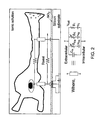
- Fig. 1 illustrates a general neuroelectronic hybrid system, which provides for both electrical (left hand side) and chemical (right hand side) communication.
- FIG. 2 there is illustrated a scheme defining the geometrical relations between a cultured neuron and the transistor gate, and a high seal resistance R seal between the body of the biological solution and the neuron-transistor coupling area.
- the inventors investigated the parameters that determine the efficiency of the coupling coefficients and recognized the following major obstacles in constructing efficient, reliable and durable neuro-electronic hybrids:
- the seal resistance depends on the dimensions of the space formed between the transistors floating gate surface and the plasma membrane facing the gate. The geometry and dimensions of this space defines the value of the seal resistance R seal formed between the center of the neuron-gate contact area and the non-contacting region.
- Theoretical considerations [2-4], as well as experimental considerations show that the larger R seal , the better the electrical coupling. Hence, an electronic device should be designed so as to provide reliably increased R seal .
- a characteristic feature of neurons is their structural plasticity. Under in vivo conditions neurons change their morphology and connectivity during development, after injury and in relation to various forms of learning and memory processes. Likewise, cultured neurons do not maintain a constant position on the device surface [5]. This mobility results in continuous translocation of the cell body, axons and dendrites in respect to the device surface. As a consequence, instability in the shape and amplitude of the recorded potential occur. Additionally, a large fraction of cultured neurons is often not forming an appropriate physical contact with the sensing device and thus functional contact with the surface electrodes is not established.
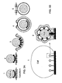
- Phagocytosis consists of a process of engulfing foreign particles by cells, and presents a phenomenon of fundamental importance for a large number of cells types and organisms. It is known to be a mean to internalize food (in protozoa), cellular debris (macrophages and neutrophils) or specific signaling molecules. Phagocytosis is defined as the cellular process that leads to the internalization of large particles in the range of up to 0.5 ⁇ m.
- Fig. 3A schematically illustrates the cellular mechanisms that underlie phagocytosis.
- Phagocytosis is an action dependent process in which extension of the plasma membrane around a particle, or the " sinking " of a particle into the cell leads to its internalization. Accordingly, the process is inhibited by cytochalasin, a toxin that interferes with the polymerization dynamics of actin filaments.
- Phagocytosis is triggered by the activation of receptors [6] such as Fc-receptors (that mediate the internalization of particles decorated by immunoglobulins), complement-receptors, integrins that mediate the uptake of particles coated with fibronectin [7], mannose receptors that internalize lectins coated particles [8] and others.
- receptors [6] such as Fc-receptors (that mediate the internalization of particles decorated by immunoglobulins), complement-receptors, integrins that mediate the uptake of particles coated with fibronectin [7], mannose receptors that internalize lectins coated particles [8] and others.
- the detached plasma membrane that contains the particle is now free to move in the cytosol and fuse with endosoms.
- a mechanism utilized in the present invention consists of internalization of the micronail which is an integral part of a surface-substrate, and provides for better anchor neurons to the surface-substrate. While phagocytosis of "stand-alone", the particle is totally engulfed by the cell, a process that requires the cell to close the membrane over the particle and form a sealed vacuole (which contains the particle - Fig. 3A , 4 in the present invention the engulfinent is of a part of a protrusion part that is of a larger surface of "stand alone " particles). As shown in Fig.
- the inventors have found that harnessing the mechanisms of phago/endocytosis provides for anchoring neurons and improving the electrical coupling between the neuron and electronic (the gate electrode which forms a part of a transistor).
- the recognition event between the extracellular domain of the cellular component of the plasma membrane, and the recognition molecule that decorate the particle (or the micronail) is the initial and essential event in the cascade that leads to phagocytosis (the tethering of the external particle and the cell). It is known that similar mechanisms and proteins provide also the essential component for the assembly of adhesion junctions.
- similar molecular building blocks participate in the attachment of cells to the substrate and to particles that are then phagocytosed.
- talin that binds both cytoskeletal and signaling molecules, vinculin and paxillin. This approach is supported by a number of experiments which demonstrate that if a legend mediating phagocytosis is present over a sufficient large substrate area, the cultured cells will attach to the substrate and form adhesion junctions.
- the junction formed between the cells and the micronail is stable.
- This junction is a functional connection between the electron/transistor and the cell (e.g., neuron) enabling signal transfer in at least one direction, either from the transistor to the cell or from the cell to the transistor through capacitive coupling.
- a suitable model for realizing the principles of internalization of the micronails heads is the internalization of beads.
- the inventors have developed optimal surface chemistry that induces neurons to phagocytose polystyren beads with diameters ranging between 0.2-0.5 ⁇ m. To this end, the following was carried out:
- EXAMPLE 2 INDUCTION OF ENDOCYTOSIS BY FRAGMENTS OF NEURONAL CELLS
- Figs. 4A-4D illustrate the results (electron micrographs of endocytotic phagocytotic profiles) of another experiment performed by the inventors where the assembly of the sub-membrane coat and endocytosis was induced by exposing cultured Aplysia neurons to fragments of other neurons.
- Fig. 4A shows the induction of endocytosis, where " 1 " denotes an initial stage, noting the darkening of the membrane just beneath the particle on the right hand side of the micrograph, " 2 " corresponds to the state when plasma membrane begins to invaginate, and " 3 " notes the increase curvature of the plasma membrane.
- Fig. 4B shows the induction of an endocytotic profile by a particle.
- Fig. 4C shows the endocytotic profile.
- Fig. 4D shows a coated vesicle containing a cell fragment. The dimensions of the profile and coated vesicle are 0.3-0.5 ⁇ m, the dimensions of the golden head of the micronails.
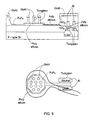
- Figs. 5 and 6 illustrate an electronic device (transistor) according to the invention utilizing a gate electrode (poly-silicon floating gate in the present example) formed with micronails, which are protruding from gate electrode surface.
- Fig. 5 shows an over view of the micronails configuration on the floating gate
- Fig. 6 shows the scaled cross-section of the 'nail' structure. As shown, many micronails are provided protruding from a single gate.
- the base (stem-like portion) of micronail type A is preferably made of tungsten (but generally from any other suitable electrically conductive material) and is electrically isolated from the solution in which the neurons (or other cell types) are embedded by a layer of silicon nitride of about 20nm in thickness.
- the top surface of the poly-silicon around the nails, in the plane of the transistor, is isolated from the solution by a layer of silicon nitride of about 40nm.
- a cap (head portion) of gold or another metal such as for example copper, aluminum, platinum and silver, obtained by standard electroplating or electrolyses plating technique, which is performed on the finished wafers.
- An alternative process for the formation of the metal cap is by the use of standard lithography.
- Fig. 7 shows two types of the Floating Gate Depletion type Transistor (FGDT) based micronails sensors: Type A devices are designed to enhance contact with neurons by applying various surface chemistries that facilitate wrapping of the nails by the cell's membrane, and Type B devices present a modification of the type A devices and are tailored to enhance sensitivity to molecular recognition events and chemical processes, with or without cells presence. Both FGDT types are fabricated using standard CMOS processing steps.
- FGDT Floating Gate Depletion type Transistor
- Additional layers of chemically active molecules can be added on top of the nail head to enhance the swallowing of the micronail's head into the neuron, as will be described further below.
- a major concern of the micronails structure of the present invention is the influence of the nail on the neuron-transistor electrical coupling by short-circuiting the floating gate ( Fig 5 ). This is relevant only to floating gates connected to micronails that are not engulfed by a neuron.
- the exposed nail simply shorts the floating gate to the biological solution via the gold head.
- there is an isolating layer (of about 20nm thickness) over the entire nail surface including the gold head. This insulating layer still increases significantly the capacitive coupling of the floating gate to the ionic solution, consequently reduces the electrical coupling of the neuron to the floating gate by other nails that are engulfed by the neuron.
- the problem of coupling can be solved in one of the following ways:
- the technique of the present invention provides two new approaches applicable to native proteins.
- the first approach is to introduce programmed lifetime of enzymes via the use of biodegradable linkers, and the second approach relies on durable aromatic linkers that enhance the electronic coupling of molecular recognition events to the gold (or oxide) containing floating gate (vide infra ).
- the type A micronails are fabricated from biocompatible metals, for example tungsten rods that are integral part of the gate but insulated from the surrounding by oxide or nitride layers.
- the bases of the nails are terminated with gold hemispheres ( Fig. 7 ).
- the molecular decoration of these nails is differentiated according to the various exposed surfaces: gold for the heads and nitride or oxide for the bases.
- the molecularly modified gold heads present to the cultured cells plasma membrane chemical signals that facilitate its physical uptake by phagocytotic or endocytotic mechanisms (as described above with reference to Figs. 4 and 5 ).
- the component of the self-assembled monolayers containing nitride base acts as the cell adhesion interfaces.
- the nails in this case are fabricated from poly-silicon rods/bases or other combinations of conductive layers that are integral part of the transistor gate. However, they are insulated from the surrounding by a thin insulating layer that is formed on top of the rod following etching of the nitride layer.
- the surface area of the floating gate thermal-oxide coating is maximized to allow better molecular sensing ability and polarization mediated potential sensing.
- a layer of moieties that promote internalization is present on the coating (not-shown in the figure).
- the technique of the present invention aimed at promoting the internalization of the micronails heads is based on their functionalization by molecules that perform at least one of the following three functions:
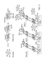
- Fig. 8 illustrates a process of adhering hydrolytic enzymes to the nails heads surface, showing the micronails' head assembled with phagocytosis signaling peptides (PSP) and hydrolytic enzymes (HE) connected via biodegradable spacer (poly(lactic-acid) - PGA or poly(gluconic-acid)- PGA).
- PSP phagocytosis signaling peptides
- HE hydrolytic enzymes
- These hydrolytic enzymes include: polysaccharide-degrading enzymes (e.g., sialidase, neuraminidase, hyaluronidases and the like), proteinases including carboxypeptidase and collagenases, and lipid-degrading-enzymes (e.g., lipases and phospholipases).
- the lifetime of the hydrolytic enzymes anchored to the gold hemisphere is limited by biodegradability (or "spontaneous" hydrolysis) of the linker chains.
- the implanted enzymes do not affect the phagocytosis signaling peptides.
- the biodegradable linker chain is synthesized from poly(lactic-acid) (PLA) or poly(gluconic-acid) (PGA) that are non-substrates for the HE used in here.
- PKA poly(lactic-acid)
- PGA poly(gluconic-acid)
- carboxypeptidase A is used as the peptide digesting enzyme and the phagocytosis signaling peptides is anchored to the surface through the N-terminal and blocked by t-Bu group at the C-terminal preventing the enzyme recognition and hydrolysis.
- Hyperpolarizable molecular transducers can be assembled directly on the nail's Au (type A ) or SiO 2 (type B) exposed area and their head groups anchor plasma membrane surface molecules. Integrins typically recognize short linear amino acid sequences in ECM proteins, one of the most common being Arginine-Glycine-Aspartate (RGD). Such peptides are grafted onto the gold surfaces via attachment at the N-terminal to surface grafted active ester.
- RGD Arginine-Glycine-Aspartate
- Fig. 10 illustrates peptide anchoring to the base, nitride regions and to the gold nail-heads containing chromophoric layer, in type A devices.
- chromophores containing surfaces are also grafted with peptides.
- type B devices chromophores containing surfaces are assembled on SiO 2 surfaces by treating the surface with the appropriate coupling agent (e.g., 3-bromopropyl(trichlorosilane)), and thus the device will couple alkylhalide functionality to the oxide in step i, followed by steps ii-iv as shown in the example of RGD coupling of Fig. 10 .
- the appropriate coupling agent e.g., 3-bromopropyl(trichlorosilane)
- the second approach according to the invention for creating intimate neuron-nail contacts relies on recognition sites of hyaluronan, the polysaccharide part of proteoglycan in the extracellular matrix.
- the glucosaminoglycan repeating unit of hyaluronan or sialic acid can be easily coupled via siloxane linkages of the sugar's hydroxyl-group. This coupling can be conducted directly on the nitride surface and via chromophoric layer self-assembled on the gold-heads in type A devices and on the oxide rods in type B devices. This is illustrated in Fig.
- Type A devices showing saccharides anchoring to the nitride regions and to the gold nail-heads containing chromophoric layer, in type A devices.
- Type B devices will couple alkylhalide functionality to the oxide in step i, followed by steps ii-iv.
- Hyaluronic acid and Sialic acid coupling is given as a non-limiting example.
- the inventors have developed the 2D-PAN, a positively charged monolayer of polyaniline, to adhere the plasma membrane to the micronail stem and the active planes of the transistor (e.g., FGDT).
- the main steps of this method are illustrated in Fig. 12 .
- the method relies on the electrostatic assembly of a monolayer of monomers (anilinium-ions) followed by their polymerization (to polyaniline, PAN).
- Polyanion (polystyrenesulfonate sodium salt, PSS) deposition has led to rougher surfaces than the small-molecules containing template layer.
- the electrostatic adhesion of the positively charged anilinium monomers is followed by chemical oxidation with ammonium-peroxydisulfate or enzymatically with horseradish-peroxidase (HRP) to yield the 2D-PAN.
- HRP horseradish-peroxidase
- PSS template layer for 2D-PAN self-assembly has created a special interface for neurons growth.
- the combination of positively charged (quaternary amines) and rough interface has led to very strong cell adhesion to the micronail.
- This layer over the standard neurophilic layers (e.g., laminine, poly-D-lysine, and fibronectin.) are associated with their diminished vertical dimensionality and reduced electrical resistively.
- a better capacitive coupling between neurons and MOS-devices is provided when the neurons are placed closer to the sensing area (2-4 nm vs. few hundreds) and where the membrane potential is less shielded (conducting polymer vs. insulating layers).
- the coupling of the neurons to the nitride- and oxide-containing surfaces of the device should add to the sensitivity of both device types.
- the assembly of 2D-PAN to gold surfaces has been developed [18] and can be straight-forward implemented to the micronail Au-head.
- the inventors have studied the warping of Au-nanoparticles (NP) with PAN-monolayers, and investigated their interface with Aplysia neurons.
- the adherence of Aplysia neuron to self-assembled PAN monolayer on an electrostatically bound Au-NP to positively charged glass substrate is illustrated in Fig. 13 - an electron microscopy image of the interface between Aplysia's plasma membrane and a monolayer of 5nm Au particles self-assembled with 2D-PAN monolayer on a glass substrate.
- the tight junction (of about 10-30 nm) is indicative of the decrease in R seal and the enhanced sensitivity of the micronail containing FGDT based neurosensors.
- Fig. 14 illustrates an example of a short and rigid molecular coupling of receptor or enzyme to the gold head by first assembling p -aminothiophenol followed by condensing cyanuric acid allowing coupling of the receptor/enzyme through amine condensation.
- neurotransmitter site is shown containing proteins (enzyme/receptor, E/R) anchoring to gold surfaces via rigid and short spacer ( type A ).
- the assembly to oxide surfaces is conducted similarly excluding step i (type B), as disclosed in PCT/IL03/100941 assigned to the assignee of the present application.
- the formation of chemical synapse composed of a neuronal presynaptic element and an electronic device that serves, as a post-synaptic element enables to link neurons to the electronic device not only by electrical signals but also by released neurotransmitters and the electric device in such a case can detect said release.
- Such chemical linkage opens up a novel way to link the nervous system with the electronic world and allows simulating the natural way by which neurons as well as neurons and muscles communicate with each other. It should be emphasized in this respect the unidirectional communication between excitable cells is mainly executed by chemical synapses.
- the inventors have developed a highly sensitive (10 -8 M) sensor for acetylcholine and conducted experiments in which polystyrene beads coated with bioactive molecules were shown to induce the ultrastructural differentiation of presynaptic terminal.
- the micronails surface can be coated with a variety of signaling molecules (as described above) and receptor molecules that recognize and binds acetylcholine, glutamate, GABA, serotonin and others.
Landscapes
- Chemical & Material Sciences (AREA)
- Engineering & Computer Science (AREA)
- Health & Medical Sciences (AREA)
- Life Sciences & Earth Sciences (AREA)
- Nanotechnology (AREA)
- Physics & Mathematics (AREA)
- Organic Chemistry (AREA)
- General Health & Medical Sciences (AREA)
- Molecular Biology (AREA)
- General Physics & Mathematics (AREA)
- Biochemistry (AREA)
- Biophysics (AREA)
- Crystallography & Structural Chemistry (AREA)
- Biomedical Technology (AREA)
- Proteomics, Peptides & Aminoacids (AREA)
- Power Engineering (AREA)
- Medicinal Chemistry (AREA)
- Microelectronics & Electronic Packaging (AREA)
- Analytical Chemistry (AREA)
- Wood Science & Technology (AREA)
- Genetics & Genomics (AREA)
- Immunology (AREA)
- Condensed Matter Physics & Semiconductors (AREA)
- Zoology (AREA)
- Food Science & Technology (AREA)
- Hematology (AREA)
- Pathology (AREA)
- Biotechnology (AREA)
- Microbiology (AREA)
- Computer Hardware Design (AREA)
- Urology & Nephrology (AREA)
- Bioinformatics & Cheminformatics (AREA)
- General Engineering & Computer Science (AREA)
- Inorganic Chemistry (AREA)
- Ceramic Engineering (AREA)
- Composite Materials (AREA)
- Materials Engineering (AREA)
- Mathematical Physics (AREA)
- Theoretical Computer Science (AREA)
- Apparatus Associated With Microorganisms And Enzymes (AREA)
Claims (43)
- Ein Oberflächensubstrat für die Anhaftung von Zellen daran, das Folgendes umfasst:mindestens eine Mikrostiftstruktur, die aus der Oberfläche herausragt, wobei die Mikrostiftstruktur ein Herausragen in der Größenordnung von Mikrometern oder Nanometern ist, umfassend einen Stab-ähnlichen Basisabschnitt und einen Kappen-ähnlichen Kopfabschnitt, der größer ist im Durchmesser als der Stab-ähnliche Basisabschnitt, wobei mindestens ein Bereich des Mikrostift-Kappen-ähnlichen Basisabschnitts zelluläre Internalisierungs-fördernde Eigenschaften hat, so dass eine zelluläre Membran in der Lage ist, um den Kopfabschnitt gewickelt zu werden, und der Mikrostift in der Lage ist von der Membran eingehüllt zu werden.
- Das Oberflächensubstrat gemäß Anspruch 1, worin mindestens der Abschnitt des Mikrostifts mit zellulären Internalisierungs-fördernden Einheiten beschichtet ist.
- Ein Oberflächensubstrat gemäß Anspruch 1, worin der Kopfanteil mit zellulären Internalisierungs-fördernden Einheiten beschichtet ist.
- Das Oberflächensubstrat gemäß irgendeinem der Ansprüche 2 bis 3, worin die zellulären Internalisierungs-fördernden Einheiten gewählt sind aus:(a) hydrolytischen Enzymen, die die Degradation von extrazellulärer Matrix erleichtern;(b) Molekülen, die Plasmamembrankomponenten erkennen, welche auf der externen Oberfläche der Plasmamembran von Zellen befindlich sind;(c) einer Kombination aus (a) und (b).
- Das Oberflachensubstrat gemäß Anspruch 1, worin der Kopfabschnitt zusammengesetzt ist aus oder beschichtet ist mit einem Metall-enthaltenden Material.
- Das Oberflächensubstrat gemäß Anspruch 5, worin das Metall gewählt ist aus: Gold, Kupfer, Aluminium, Platin, Silber, Legierungen aus solchen Metallen oder Kombinationen aus solchen Metallen.
- Das Oberflächensubstrat gemäß Anspruch 4, worin das hydrolytische Enzym gewählt ist aus Polysaccharid-degradierenden Enzymen, Proteinasen und Lipid-degradierenden Enzymen.
- Das Oberflächensubstrat gemäß Anspruch 7, worin das hydrolytische Enzym durch ein bioabbaubares Spacermolekül an den Mikrostift angeknüpft ist.
- Das Oberflächensubstrat gemäß Anspruch 4, worin die Moleküle, die Plasmamembrankomponenten erkennen, gewählt sind aus: Liganden von Plasmamembranrezeptoren oder Rezeptorbindungsteilen von solchen Liganden; Rezeptoren, die Plasmamembrankomponenten erkennen; Lektinen, die an Plasmamembran-Glycoproteine binden; Antikörpern, die Plasmamembrankomponenten oder bindende Fragmente davon erkennen; Integrinen, die kurze lineare Aminosäuresequenzen in ECM-Proteinen erkennen; oder einer Kombination aus zwei oder mehreren der oben genannten.
- Das Oberflächensubstrat gemäß Anspruch 4, worin die Moleküle, die Plasmakomponenten erkennen, Moleküle sind, welche an Polysaccharide binden, die Teil von Proteoglykanen in der ECM-Plasmamembran sind.
- Das Oberflächensubstrat gemäß Anspruch 1, weiter umfassend Moleküle, die die Adhäsion von Zellen fördern.
- Das Oberflächensubstrat gemäß Anspruch 3 und 11, worin die Moleküle, die die Adhäsion von Zellen fördern, auf mindestens einem der Folgenden vorhanden sind: dem Basisabschnitt des Mikrostifts, und der Region, die den Basisabschnitt umgibt.
- Das Oberflächensubstrat gemäß Anspruch 11, worin die Adhäsionsmoleküle in der Form einer geladenen Monoschicht vorliegen.
- Das Oberflächensubstrat gemäß Anspruch 13, worin die geladene Monoschicht eine positiv geladene Monoschicht von Polylysin, Polyanilin und einem ähnlichen ist.
- Das Oberflächensubstrat gemäß Anspruch 14, worin die positiv geladene Monoschicht von Polylysin, Polyanilin und einem ähnlichen, auf einer Polystyrensulfonatschicht angeordnet ist, wobei die Polystyrensulfonatschicht Anioneinheiten umfasst, die durch einen Linker an den Mikrostift angeknüpft sind.
- Ein Oberflächensubstrat gemäß irgendeinem der Ansprüche 1-15, worin die Oberfläche angepasst ist, um einen Zellkommunizierenden Teil einer Elektrode zu bilden.
- Ein Oberflächensubstrat gemäß Anspruch 16, worin die Elektrode eine Gate-Elektrode ist.
- Ein Oberflächensubstrat gemäß Anspruch 16 oder 17, worin der Basisabschnitt des Mikrostifts von seiner Umgebung elektrisch isoliert ist.
- Ein Oberflächensubstrat gemäß Anspruch 16 oder 17, worin der Mikrostift von seiner Umgebung elektrisch isoliert ist.
- Ein Oberflächensubstrat gemäß Anspruch 17, worin der Mikrostift ein leitender Stift ist, wie zum Beispiel ein Polysiliziumstift, der ein integraler Bestandteil der Poly-Silizium-Gate-Elektrode ist, und isoliert ist von der Umgebung durch eine dünne Isolierungsschicht.
- Ein Oberflächensubstrat gemäß Anspruch 17, in der Form einer integrierten Struktur, hergestellt durch Lithographie und Ätztechniken.
- Ein Oberflächensubstrat gemäß Anspruch 18, worin der Basisabschnitt des Mikrostifts aus Wolfram hergestellt ist und von der Umgebung durch eine Schicht von Siliziumnitrid isoliert ist.
- Das Oberflächensubstrat gemäß Anspruch 1, worin der Kopf des Mikrostifts bedeckt ist mit einem Material, das die Penetration des Mikrostifts in ein Zytoplasma ermöglicht, so dass der Mikrostift bedienbar ist als eine Mikrospritze für die Zuführung von Materialien entweder an die Plasmamembran oder intrazellulär.
- Eine Elektrode umfassend eine Oberfläche, die die mindestens eine Mikrostiftstruktur gemäß Anspruch 1 umfasst, wobei die Oberfläche dabei eine Zell-kommunizierende Komponente der Elektrode bildet.
- Eine Elektrode gemäß Anspruch 24, die eine Gate-Elektrode ist.
- Eine Elektrode gemäß Anspruch 25, die einen einzelnen Mikrostift hat.
- Eine Elektrode gemäß Anspruch 25, die eine Gruppe von Mikrostiften hat.
- Eine Elektrode gemäß Anspruch 27, worin die Größe der Gruppe kleiner ist als die Größe der Zelle, die in Kommunikation mit der Elektrode sein soll.
- Eine Elektrode gemäß Anspruch 24 oder 25, die mit einer Schicht von immobilisierten Erkennungsmolekülen beschichtet ist, welche in der Anwesenheit von Zell-abgesonderten Komponenten in der Lage sind, eine Reaktion zu katalysieren, die die Freisetzung von Ionen in ein Medium, das das Erkennungsmolekül umgibt, bewirkt.
- Eine Elektrode gemäß Anspruch 29, die eine Gate-Elektrode ist.
- Eine Elektrode gemäß Anspruch 29, worin der Abstand zwischen den Erkennungsmolekülen und der Oberfläche des beschichteten Gates kleiner ist als 15Å.
- Eine Elektrode gemäß Anspruch 29 oder 30, worin die Erkennungsmoleküle Enzyme oder Peptide sind.
- Eine Elektrode gemäß Anspruch 32, worin die Erkennungsmoleküle in der Lage sind die Reaktion zu katalysieren in der Anwesenheit einer Zell-abgesonderten Komponente gewählt aus Acetylcholin, Glutamat, GABA, Serotonin, Neurotransmittern und / oder Neuroendokrinen, Wachstumsfaktoren, Zytokinen.
- Eine Elektrode gemäß Anspruch 33, worin das Erkennungsmolekül Acetylcholinesterase ist.
- Eine Elektrode gemäß Ansprüchen 30, worin die Gate-Elektrode ein Ionen-empfindliches Gate ist.
- Eine Elektrode gemäß Anspruch 35, worin das Ionenempfindliche Material Aluminiumoxid (Al2O3), Siliziumnitrid (Si3N4), Indiumzinnoxid (In2O3-Sn2O3), Siliziumoxid (SiO2) oder Tantaloxid (Ta2O5) ist.
- Eine Elektrode gemäß Anspruch 29 oder 30, worin die Erkennungsmolektile über Linkermoleküle immobilisiert sind, die kovalent gebunden sind an mindestens eines von dem Oberflächensubstrat und den Erkennungsmolekülen.
- Eine Elektrode gemäß Anspruch 37, worin die Linkermoleküle gewählt sind aus konjugierten oder unkonjugierten aliphatischen, aromatischen oder heteroatomatischen Molekülen, die mindestens eine funktionelle Gruppe haben, die in der Lage ist, kovalent an die Oberfläche zu binden, und mindestens eine funktionelle Gruppe, die in der Lage ist kovalent an die Erkennungsmoleküle zu binden.
- Eine Vorrichtung für die Detektion von Zell-absondernden Komponenten umfassend eine Elektrodenanordnung, die mindestens eine Elektrode gemäß Anspruch 29 oder 30 hat.
- Eine Vorrichtung für die Detektion von Zell-absondernden Komponenten umfassend mindestens ein Paar von Source-Drain-Elektroden und mindestens eine Gate-Elektrode gemäß Anspruch 31, die zusammen mindestens einen Feld-Effekt-Transistor (FET) bilden.
- Eine Vorrichtung für die elektrische Kommunikation mit einer Zelle umfassend eine Elektrodenanordnung, die mindestens eine Elektrode gemäß Anspruch 24 oder 25 hat.
- Eine Vorrichtung für die elektrische Kommunikation mit einer Zelle umfassend mindestens ein Paar von Source-Drain-Elektroden und mindestens eine Gate-Elektrode wie in Anspruch 25 definiert, wodurch zusammen mindestens ein Feld-Effekt-Transistor (FET) definiert wird.
- Eine Vorrichtung gemäß irgendeinem der Anspruch 41 oder 42, worin die elektrische Kommunikation mit der Zelle durch eine Eigenschaft erreicht wird, die gewählt ist aus;(a) Detektieren der Anwesenheit von Strom, oder Stromänderungen in Zellen;(b) Detektierten von Feldpotential oder Feldpotential-Änderung in Zellen;(c) Bereitstellen eines Stroms zu den Zellen;(d) Bereitstellen von Feldpotential zu den Zellen;(e) eine Kombination aus zwei oder mehreren von (a) bis (d).
Applications Claiming Priority (2)
| Application Number | Priority Date | Filing Date | Title |
|---|---|---|---|
| US47703703P | 2003-06-10 | 2003-06-10 | |
| PCT/IL2004/000502 WO2004109282A1 (en) | 2003-06-10 | 2004-06-10 | Electronic device for communication with living cells |
Publications (2)
| Publication Number | Publication Date |
|---|---|
| EP1634075A1 EP1634075A1 (de) | 2006-03-15 |
| EP1634075B1 true EP1634075B1 (de) | 2015-01-14 |
Family
ID=33511831
Family Applications (1)
| Application Number | Title | Priority Date | Filing Date |
|---|---|---|---|
| EP04736573.9A Not-in-force EP1634075B1 (de) | 2003-06-10 | 2004-06-10 | Elektronische Vorrichtung zur Kommunikation mit lebenden Zellen |
Country Status (4)
| Country | Link |
|---|---|
| US (1) | US7795039B2 (de) |
| EP (1) | EP1634075B1 (de) |
| JP (1) | JP4728956B2 (de) |
| WO (1) | WO2004109282A1 (de) |
Families Citing this family (48)
| Publication number | Priority date | Publication date | Assignee | Title |
|---|---|---|---|---|
| JP4728956B2 (ja) | 2003-06-10 | 2011-07-20 | イサム リサーチ デベロップメント カンパニー オブ ザ ヘブルー ユニバーシティ オブ エルサレム | 生体細胞との通信のための電子装置 |
| GB0322010D0 (en) * | 2003-09-19 | 2003-10-22 | Univ Cambridge Tech | Detection of molecular interactions using field effect transistors |
| CA2643997A1 (en) * | 2006-03-15 | 2008-03-06 | President And Fellows Of Harvard College | Nanobioelectronics |
| JP2009540333A (ja) | 2006-06-12 | 2009-11-19 | プレジデント アンド フェロウズ オブ ハーバード カレッジ | ナノセンサーおよび関連技術 |
| WO2008021758A1 (en) * | 2006-08-11 | 2008-02-21 | Home Diagnostics, Inc. | Methods for fabricating a biosensor with a surface texture |
| WO2008127314A1 (en) | 2006-11-22 | 2008-10-23 | President And Fellows Of Harvard College | High-sensitivity nanoscale wire sensors |
| US8349167B2 (en) | 2006-12-14 | 2013-01-08 | Life Technologies Corporation | Methods and apparatus for detecting molecular interactions using FET arrays |
| US8262900B2 (en) | 2006-12-14 | 2012-09-11 | Life Technologies Corporation | Methods and apparatus for measuring analytes using large scale FET arrays |
| US11339430B2 (en) | 2007-07-10 | 2022-05-24 | Life Technologies Corporation | Methods and apparatus for measuring analytes using large scale FET arrays |
| EP2653861B1 (de) | 2006-12-14 | 2014-08-13 | Life Technologies Corporation | Verfahren zur Nukleinsäure-Sequenzierung mittels großer FET-Arrays |
| WO2008111047A1 (en) * | 2007-03-09 | 2008-09-18 | Imec Vzw | Micro-nails for use in electrical interaction with cells |
| US10202711B2 (en) * | 2007-05-09 | 2019-02-12 | Massachusetts Institute Of Technology | Tunable surface |
| ES2517919T3 (es) * | 2008-09-02 | 2014-11-04 | The Governing Council Of The University Of Toronto | Microelectrodos nanoestructurados y dispositivos de biodetección que los incorporan |
| US20100137143A1 (en) | 2008-10-22 | 2010-06-03 | Ion Torrent Systems Incorporated | Methods and apparatus for measuring analytes |
| US20100301398A1 (en) | 2009-05-29 | 2010-12-02 | Ion Torrent Systems Incorporated | Methods and apparatus for measuring analytes |
| US9304132B2 (en) | 2009-04-16 | 2016-04-05 | President And Fellows Of Harvard College | Molecular delivery with nanowires |
| US20120261274A1 (en) | 2009-05-29 | 2012-10-18 | Life Technologies Corporation | Methods and apparatus for measuring analytes |
| US8776573B2 (en) | 2009-05-29 | 2014-07-15 | Life Technologies Corporation | Methods and apparatus for measuring analytes |
| US9297796B2 (en) | 2009-09-24 | 2016-03-29 | President And Fellows Of Harvard College | Bent nanowires and related probing of species |
| AU2011226767B1 (en) | 2010-06-30 | 2011-11-10 | Life Technologies Corporation | Ion-sensing charge-accumulation circuits and methods |
| US8487790B2 (en) | 2010-06-30 | 2013-07-16 | Life Technologies Corporation | Chemical detection circuit including a serializer circuit |
| TWI569025B (zh) | 2010-06-30 | 2017-02-01 | 生命技術公司 | 用於測試離子感測場效電晶體(isfet)陣列之裝置及方法 |
| US11307166B2 (en) | 2010-07-01 | 2022-04-19 | Life Technologies Corporation | Column ADC |
| EP2589065B1 (de) | 2010-07-03 | 2015-08-19 | Life Technologies Corporation | Chemisch empfindlicher sensor mit leicht dotierten abflüssen |
| WO2012036679A1 (en) | 2010-09-15 | 2012-03-22 | Life Technologies Corporation | Methods and apparatus for measuring analytes |
| AU2011226766A1 (en) | 2010-09-24 | 2012-04-12 | Life Technologies Corporation | Matched pair transistor circuits |
| US9629995B2 (en) | 2011-05-26 | 2017-04-25 | Yissum Research Development Company Of The Hebrew University Of Jerusalem Ltd. | Biomolecular electronic device and process of use |
| US9595685B2 (en) | 2011-06-10 | 2017-03-14 | President And Fellows Of Harvard College | Nanoscale wires, nanoscale wire FET devices, and nanotube-electronic hybrid devices for sensing and other applications |
| KR101774480B1 (ko) * | 2011-08-16 | 2017-09-04 | 에레즈 할라미 | 전계 효과 트랜지스터의 비접촉 제어를 위한 방법 및 장치 그리고 두 개의 전자 장치들을 상호연결하는 방법 |
| KR101366391B1 (ko) * | 2011-10-05 | 2014-02-25 | 한양대학교 산학협력단 | 세포 계수용 칩 |
| US9970984B2 (en) | 2011-12-01 | 2018-05-15 | Life Technologies Corporation | Method and apparatus for identifying defects in a chemical sensor array |
| US8786331B2 (en) | 2012-05-29 | 2014-07-22 | Life Technologies Corporation | System for reducing noise in a chemical sensor array |
| US9080968B2 (en) | 2013-01-04 | 2015-07-14 | Life Technologies Corporation | Methods and systems for point of use removal of sacrificial material |
| US9841398B2 (en) | 2013-01-08 | 2017-12-12 | Life Technologies Corporation | Methods for manufacturing well structures for low-noise chemical sensors |
| US8963216B2 (en) | 2013-03-13 | 2015-02-24 | Life Technologies Corporation | Chemical sensor with sidewall spacer sensor surface |
| US9835585B2 (en) | 2013-03-15 | 2017-12-05 | Life Technologies Corporation | Chemical sensor with protruded sensor surface |
| JP6671274B2 (ja) | 2013-03-15 | 2020-03-25 | ライフ テクノロジーズ コーポレーション | 薄伝導性素子を有する化学装置 |
| US20140264472A1 (en) | 2013-03-15 | 2014-09-18 | Life Technologies Corporation | Chemical sensor with consistent sensor surface areas |
| US20140336063A1 (en) | 2013-05-09 | 2014-11-13 | Life Technologies Corporation | Windowed Sequencing |
| US10458942B2 (en) | 2013-06-10 | 2019-10-29 | Life Technologies Corporation | Chemical sensor array having multiple sensors per well |
| TWI647842B (zh) * | 2013-08-22 | 2019-01-11 | 美商生命技術公司 | 具薄導電元件之化學裝置 |
| WO2016100521A1 (en) | 2014-12-18 | 2016-06-23 | Life Technologies Corporation | Methods and apparatus for measuring analytes using large scale fet arrays |
| CN107250784B (zh) | 2014-12-18 | 2020-10-23 | 生命科技公司 | 具有发送器配置的高数据率集成电路 |
| US10077472B2 (en) | 2014-12-18 | 2018-09-18 | Life Technologies Corporation | High data rate integrated circuit with power management |
| WO2016112315A2 (en) | 2015-01-09 | 2016-07-14 | President And Fellows Of Harvard College | Nanowire arrays for neurotechnology and other applications |
| GB201512600D0 (en) * | 2015-07-17 | 2015-08-26 | Koniku Ltd | Cell culture, transport and investigation |
| US11474103B2 (en) | 2017-02-17 | 2022-10-18 | Koniku Inc. | Systems for detection |
| CN107085097B (zh) * | 2017-05-14 | 2020-08-28 | 浙江达普生物科技有限公司 | 一种血检芯片及其制作方法 |
Citations (1)
| Publication number | Priority date | Publication date | Assignee | Title |
|---|---|---|---|---|
| US20020053915A1 (en) * | 2000-07-07 | 2002-05-09 | Weaver Charles David | Electrophysiology configuration suitable for high throughput screening of compounds for drug discovery |
Family Cites Families (13)
| Publication number | Priority date | Publication date | Assignee | Title |
|---|---|---|---|---|
| US4546083A (en) * | 1983-04-22 | 1985-10-08 | Stolle Research & Development Corporation | Method and device for cell culture growth |
| US6846654B1 (en) * | 1983-11-29 | 2005-01-25 | Igen International, Inc. | Catalytic antibodies as chemical sensors |
| CA2157388C (en) * | 1993-03-01 | 1998-12-15 | Daniel P. Witt | Analogs for specific oligosaccharide-protein interactions and uses thereof |
| DE19841337C1 (de) | 1998-05-27 | 1999-09-23 | Micronas Intermetall Gmbh | Verfahren und Vorrichtung zur intrazellulären Manipulation einer biologischen Zelle |
| JP3515908B2 (ja) | 1998-09-24 | 2004-04-05 | エヌ・ティ・ティ・アドバンステクノロジ株式会社 | 微少量オンラインバイオセンサー及びその製造方法 |
| IL145020A0 (en) * | 1999-02-22 | 2002-06-30 | Yissum Res Dev Co | A hybrid electrical device with biological components |
| JP2001156398A (ja) | 1999-05-19 | 2001-06-08 | Canon Inc | 半導体素子の製造方法、半導体素子、及びジャイロ |
| CN1204404C (zh) * | 1999-10-01 | 2005-06-01 | 索菲昂生物科学有限公司 | 电生理学性质的测定组件及其构照方法 |
| US6465331B1 (en) * | 2000-08-31 | 2002-10-15 | Micron Technology, Inc. | DRAM fabricated on a silicon-on-insulator (SOI) substrate having bi-level digit lines |
| US6914279B2 (en) | 2002-06-06 | 2005-07-05 | Rutgers, The State University Of New Jersey | Multifunctional biosensor based on ZnO nanostructures |
| IL152746A0 (en) | 2002-11-11 | 2003-06-24 | Yissum Res Dev Co | Biosensor for molecules |
| JP4728956B2 (ja) | 2003-06-10 | 2011-07-20 | イサム リサーチ デベロップメント カンパニー オブ ザ ヘブルー ユニバーシティ オブ エルサレム | 生体細胞との通信のための電子装置 |
| US7270973B2 (en) * | 2003-12-23 | 2007-09-18 | The United States Of America As Represented By The Secretary Of The Navy | Catalytic enzyme-modified textiles for active protection from toxins |
-
2004
- 2004-06-10 JP JP2006516796A patent/JP4728956B2/ja active Active
- 2004-06-10 WO PCT/IL2004/000502 patent/WO2004109282A1/en active Application Filing
- 2004-06-10 US US10/560,315 patent/US7795039B2/en not_active Expired - Fee Related
- 2004-06-10 EP EP04736573.9A patent/EP1634075B1/de not_active Not-in-force
Patent Citations (1)
| Publication number | Priority date | Publication date | Assignee | Title |
|---|---|---|---|---|
| US20020053915A1 (en) * | 2000-07-07 | 2002-05-09 | Weaver Charles David | Electrophysiology configuration suitable for high throughput screening of compounds for drug discovery |
Also Published As
| Publication number | Publication date |
|---|---|
| EP1634075A1 (de) | 2006-03-15 |
| US20070099173A1 (en) | 2007-05-03 |
| JP4728956B2 (ja) | 2011-07-20 |
| US7795039B2 (en) | 2010-09-14 |
| WO2004109282A1 (en) | 2004-12-16 |
| JP2006527380A (ja) | 2006-11-30 |
Similar Documents
| Publication | Publication Date | Title |
|---|---|---|
| EP1634075B1 (de) | Elektronische Vorrichtung zur Kommunikation mit lebenden Zellen | |
| US6703660B2 (en) | Hybrid electrical device with biological components | |
| Nam et al. | In vitro microelectrode array technology and neural recordings | |
| US10086354B2 (en) | Formation of organic nanostructure array | |
| Aubin-Tam et al. | Structure and function of nanoparticle–protein conjugates | |
| Cramer et al. | Water-gated organic field effect transistors–opportunities for biochemical sensing and extracellular signal transduction | |
| US6322963B1 (en) | Sensor for analyte detection | |
| Huang et al. | Nanoelectronic biosensing of dynamic cellular activities based on nanostructured materials | |
| US20040007740A1 (en) | Silicon-on-insulator biosensor device | |
| JP2008528446A (ja) | タンパク質ドラッグデリバリ用ナノ粒子 | |
| US9856448B2 (en) | Devices and methods for long-term intracellular access | |
| US20190021619A1 (en) | Addressable vertical nanowire probe arrays and fabrication methods | |
| Lubrano et al. | Towards biomimetic electronics that emulate cells | |
| Murcia et al. | Biofunctionalization of fluorescent nanoparticles | |
| Fan et al. | Improvement of neural cell adherence to silicon surface by hydroxyl ion implantation | |
| US20210038883A1 (en) | Auditory implant | |
| US20030054333A1 (en) | Biosensor for use in toxicity assessment and pharmacological screening | |
| US10370694B2 (en) | Size dependence of nanoparticle-protein interaction and high sensitivity potentiometric sensor exploiting such interactions | |
| Ulbrich et al. | Neuron‐Silicon Self‐Excitation: A Prototype of Iono‐Electronics | |
| EP1743665B1 (de) | Neuronenstimulation mittels Neurotransmitter unter Rückkoppelung von Sensoren | |
| US11318299B2 (en) | Visual implant | |
| WO2012160565A1 (en) | Biomolecular electronic device and process of use | |
| WO2008111047A1 (en) | Micro-nails for use in electrical interaction with cells | |
| Alghalayini | Extending the uses of lipid-membrane coated electrodes: Next generation of lipid membrane biosensors and smart implantable cell-electrode devices | |
| Sprössler et al. | Model network architectures in vitro on extracellular recording systems using microcontact printing |
Legal Events
| Date | Code | Title | Description |
|---|---|---|---|
| PUAI | Public reference made under article 153(3) epc to a published international application that has entered the european phase |
Free format text: ORIGINAL CODE: 0009012 |
|
| 17P | Request for examination filed |
Effective date: 20051230 |
|
| AK | Designated contracting states |
Kind code of ref document: A1 Designated state(s): AT BE BG CH CY CZ DE DK EE ES FI FR GB GR HU IE IT LI LU MC NL PL PT RO SE SI SK TR |
|
| DAX | Request for extension of the european patent (deleted) | ||
| 17Q | First examination report despatched |
Effective date: 20100304 |
|
| REG | Reference to a national code |
Ref country code: DE Ref legal event code: R079 Ref document number: 602004046507 Country of ref document: DE Free format text: PREVIOUS MAIN CLASS: G01N0033543000 Ipc: B82Y0015000000 |
|
| GRAP | Despatch of communication of intention to grant a patent |
Free format text: ORIGINAL CODE: EPIDOSNIGR1 |
|
| RIC1 | Information provided on ipc code assigned before grant |
Ipc: G01N 27/414 20060101ALI20140709BHEP Ipc: B82Y 30/00 20110101ALI20140709BHEP Ipc: C12Q 1/00 20060101ALI20140709BHEP Ipc: B82Y 15/00 20110101AFI20140709BHEP |
|
| INTG | Intention to grant announced |
Effective date: 20140801 |
|
| GRAS | Grant fee paid |
Free format text: ORIGINAL CODE: EPIDOSNIGR3 |
|
| GRAA | (expected) grant |
Free format text: ORIGINAL CODE: 0009210 |
|
| AK | Designated contracting states |
Kind code of ref document: B1 Designated state(s): AT BE BG CH CY CZ DE DK EE ES FI FR GB GR HU IE IT LI LU MC NL PL PT RO SE SI SK TR |
|
| REG | Reference to a national code |
Ref country code: GB Ref legal event code: FG4D |
|
| REG | Reference to a national code |
Ref country code: CH Ref legal event code: EP |
|
| REG | Reference to a national code |
Ref country code: IE Ref legal event code: FG4D |
|
| REG | Reference to a national code |
Ref country code: AT Ref legal event code: REF Ref document number: 706935 Country of ref document: AT Kind code of ref document: T Effective date: 20150215 |
|
| REG | Reference to a national code |
Ref country code: DE Ref legal event code: R096 Ref document number: 602004046507 Country of ref document: DE Effective date: 20150226 |
|
| REG | Reference to a national code |
Ref country code: NL Ref legal event code: VDEP Effective date: 20150114 |
|
| REG | Reference to a national code |
Ref country code: AT Ref legal event code: MK05 Ref document number: 706935 Country of ref document: AT Kind code of ref document: T Effective date: 20150114 |
|
| PG25 | Lapsed in a contracting state [announced via postgrant information from national office to epo] |
Ref country code: FI Free format text: LAPSE BECAUSE OF FAILURE TO SUBMIT A TRANSLATION OF THE DESCRIPTION OR TO PAY THE FEE WITHIN THE PRESCRIBED TIME-LIMIT Effective date: 20150114 Ref country code: BG Free format text: LAPSE BECAUSE OF FAILURE TO SUBMIT A TRANSLATION OF THE DESCRIPTION OR TO PAY THE FEE WITHIN THE PRESCRIBED TIME-LIMIT Effective date: 20150414 Ref country code: SE Free format text: LAPSE BECAUSE OF FAILURE TO SUBMIT A TRANSLATION OF THE DESCRIPTION OR TO PAY THE FEE WITHIN THE PRESCRIBED TIME-LIMIT Effective date: 20150114 Ref country code: ES Free format text: LAPSE BECAUSE OF FAILURE TO SUBMIT A TRANSLATION OF THE DESCRIPTION OR TO PAY THE FEE WITHIN THE PRESCRIBED TIME-LIMIT Effective date: 20150114 |
|
| PG25 | Lapsed in a contracting state [announced via postgrant information from national office to epo] |
Ref country code: AT Free format text: LAPSE BECAUSE OF FAILURE TO SUBMIT A TRANSLATION OF THE DESCRIPTION OR TO PAY THE FEE WITHIN THE PRESCRIBED TIME-LIMIT Effective date: 20150114 Ref country code: PL Free format text: LAPSE BECAUSE OF FAILURE TO SUBMIT A TRANSLATION OF THE DESCRIPTION OR TO PAY THE FEE WITHIN THE PRESCRIBED TIME-LIMIT Effective date: 20150114 Ref country code: NL Free format text: LAPSE BECAUSE OF FAILURE TO SUBMIT A TRANSLATION OF THE DESCRIPTION OR TO PAY THE FEE WITHIN THE PRESCRIBED TIME-LIMIT Effective date: 20150114 Ref country code: GR Free format text: LAPSE BECAUSE OF FAILURE TO SUBMIT A TRANSLATION OF THE DESCRIPTION OR TO PAY THE FEE WITHIN THE PRESCRIBED TIME-LIMIT Effective date: 20150415 |
|
| REG | Reference to a national code |
Ref country code: DE Ref legal event code: R097 Ref document number: 602004046507 Country of ref document: DE |
|
| PG25 | Lapsed in a contracting state [announced via postgrant information from national office to epo] |
Ref country code: EE Free format text: LAPSE BECAUSE OF FAILURE TO SUBMIT A TRANSLATION OF THE DESCRIPTION OR TO PAY THE FEE WITHIN THE PRESCRIBED TIME-LIMIT Effective date: 20150114 Ref country code: SK Free format text: LAPSE BECAUSE OF FAILURE TO SUBMIT A TRANSLATION OF THE DESCRIPTION OR TO PAY THE FEE WITHIN THE PRESCRIBED TIME-LIMIT Effective date: 20150114 Ref country code: RO Free format text: LAPSE BECAUSE OF FAILURE TO SUBMIT A TRANSLATION OF THE DESCRIPTION OR TO PAY THE FEE WITHIN THE PRESCRIBED TIME-LIMIT Effective date: 20150114 Ref country code: DK Free format text: LAPSE BECAUSE OF FAILURE TO SUBMIT A TRANSLATION OF THE DESCRIPTION OR TO PAY THE FEE WITHIN THE PRESCRIBED TIME-LIMIT Effective date: 20150114 Ref country code: CZ Free format text: LAPSE BECAUSE OF FAILURE TO SUBMIT A TRANSLATION OF THE DESCRIPTION OR TO PAY THE FEE WITHIN THE PRESCRIBED TIME-LIMIT Effective date: 20150114 |
|
| PLBE | No opposition filed within time limit |
Free format text: ORIGINAL CODE: 0009261 |
|
| STAA | Information on the status of an ep patent application or granted ep patent |
Free format text: STATUS: NO OPPOSITION FILED WITHIN TIME LIMIT |
|
| 26N | No opposition filed |
Effective date: 20151015 |
|
| PG25 | Lapsed in a contracting state [announced via postgrant information from national office to epo] |
Ref country code: IT Free format text: LAPSE BECAUSE OF FAILURE TO SUBMIT A TRANSLATION OF THE DESCRIPTION OR TO PAY THE FEE WITHIN THE PRESCRIBED TIME-LIMIT Effective date: 20150114 |
|
| PG25 | Lapsed in a contracting state [announced via postgrant information from national office to epo] |
Ref country code: MC Free format text: LAPSE BECAUSE OF FAILURE TO SUBMIT A TRANSLATION OF THE DESCRIPTION OR TO PAY THE FEE WITHIN THE PRESCRIBED TIME-LIMIT Effective date: 20150114 |
|
| REG | Reference to a national code |
Ref country code: CH Ref legal event code: PL |
|
| PG25 | Lapsed in a contracting state [announced via postgrant information from national office to epo] |
Ref country code: SI Free format text: LAPSE BECAUSE OF FAILURE TO SUBMIT A TRANSLATION OF THE DESCRIPTION OR TO PAY THE FEE WITHIN THE PRESCRIBED TIME-LIMIT Effective date: 20150114 Ref country code: LU Free format text: LAPSE BECAUSE OF FAILURE TO SUBMIT A TRANSLATION OF THE DESCRIPTION OR TO PAY THE FEE WITHIN THE PRESCRIBED TIME-LIMIT Effective date: 20150610 |
|
| REG | Reference to a national code |
Ref country code: IE Ref legal event code: MM4A |
|
| PG25 | Lapsed in a contracting state [announced via postgrant information from national office to epo] |
Ref country code: CH Free format text: LAPSE BECAUSE OF NON-PAYMENT OF DUE FEES Effective date: 20150630 Ref country code: IE Free format text: LAPSE BECAUSE OF NON-PAYMENT OF DUE FEES Effective date: 20150610 Ref country code: LI Free format text: LAPSE BECAUSE OF NON-PAYMENT OF DUE FEES Effective date: 20150630 |
|
| PG25 | Lapsed in a contracting state [announced via postgrant information from national office to epo] |
Ref country code: BE Free format text: LAPSE BECAUSE OF FAILURE TO SUBMIT A TRANSLATION OF THE DESCRIPTION OR TO PAY THE FEE WITHIN THE PRESCRIBED TIME-LIMIT Effective date: 20150114 |
|
| REG | Reference to a national code |
Ref country code: FR Ref legal event code: PLFP Year of fee payment: 13 |
|
| PG25 | Lapsed in a contracting state [announced via postgrant information from national office to epo] |
Ref country code: HU Free format text: LAPSE BECAUSE OF FAILURE TO SUBMIT A TRANSLATION OF THE DESCRIPTION OR TO PAY THE FEE WITHIN THE PRESCRIBED TIME-LIMIT; INVALID AB INITIO Effective date: 20040610 |
|
| REG | Reference to a national code |
Ref country code: FR Ref legal event code: PLFP Year of fee payment: 14 |
|
| PG25 | Lapsed in a contracting state [announced via postgrant information from national office to epo] |
Ref country code: CY Free format text: LAPSE BECAUSE OF FAILURE TO SUBMIT A TRANSLATION OF THE DESCRIPTION OR TO PAY THE FEE WITHIN THE PRESCRIBED TIME-LIMIT Effective date: 20150114 |
|
| PGFP | Annual fee paid to national office [announced via postgrant information from national office to epo] |
Ref country code: FR Payment date: 20170621 Year of fee payment: 14 Ref country code: DE Payment date: 20170621 Year of fee payment: 14 Ref country code: GB Payment date: 20170620 Year of fee payment: 14 |
|
| PG25 | Lapsed in a contracting state [announced via postgrant information from national office to epo] |
Ref country code: TR Free format text: LAPSE BECAUSE OF FAILURE TO SUBMIT A TRANSLATION OF THE DESCRIPTION OR TO PAY THE FEE WITHIN THE PRESCRIBED TIME-LIMIT Effective date: 20150114 |
|
| PG25 | Lapsed in a contracting state [announced via postgrant information from national office to epo] |
Ref country code: PT Free format text: LAPSE BECAUSE OF FAILURE TO SUBMIT A TRANSLATION OF THE DESCRIPTION OR TO PAY THE FEE WITHIN THE PRESCRIBED TIME-LIMIT Effective date: 20150114 |
|
| REG | Reference to a national code |
Ref country code: DE Ref legal event code: R119 Ref document number: 602004046507 Country of ref document: DE |
|
| GBPC | Gb: european patent ceased through non-payment of renewal fee |
Effective date: 20180610 |
|
| PG25 | Lapsed in a contracting state [announced via postgrant information from national office to epo] |
Ref country code: GB Free format text: LAPSE BECAUSE OF NON-PAYMENT OF DUE FEES Effective date: 20180610 Ref country code: DE Free format text: LAPSE BECAUSE OF NON-PAYMENT OF DUE FEES Effective date: 20190101 Ref country code: FR Free format text: LAPSE BECAUSE OF NON-PAYMENT OF DUE FEES Effective date: 20180630 |