EP1634029B1 - Rotationswärmeaustauscher und verfahren zur abdichtung eines solchen - Google Patents
Rotationswärmeaustauscher und verfahren zur abdichtung eines solchen Download PDFInfo
- Publication number
- EP1634029B1 EP1634029B1 EP04733795.1A EP04733795A EP1634029B1 EP 1634029 B1 EP1634029 B1 EP 1634029B1 EP 04733795 A EP04733795 A EP 04733795A EP 1634029 B1 EP1634029 B1 EP 1634029B1
- Authority
- EP
- European Patent Office
- Prior art keywords
- housing
- air
- rotor
- heat exchanger
- rotary heat
- Prior art date
- Legal status (The legal status is an assumption and is not a legal conclusion. Google has not performed a legal analysis and makes no representation as to the accuracy of the status listed.)
- Expired - Lifetime
Links
- 238000007789 sealing Methods 0.000 title claims description 32
- 238000000034 method Methods 0.000 title claims description 13
- 238000010926 purge Methods 0.000 claims description 8
- 230000001105 regulatory effect Effects 0.000 claims description 7
- 230000002093 peripheral effect Effects 0.000 claims description 6
- 230000007246 mechanism Effects 0.000 claims 10
- 230000008014 freezing Effects 0.000 claims 1
- 238000007710 freezing Methods 0.000 claims 1
- 238000000926 separation method Methods 0.000 description 8
- 238000004880 explosion Methods 0.000 description 4
- 239000000203 mixture Substances 0.000 description 4
- 238000007600 charging Methods 0.000 description 1
- 238000004891 communication Methods 0.000 description 1
- 238000009833 condensation Methods 0.000 description 1
- 230000005494 condensation Effects 0.000 description 1
- 238000011010 flushing procedure Methods 0.000 description 1
- 238000010438 heat treatment Methods 0.000 description 1
- 230000002000 scavenging effect Effects 0.000 description 1
- 238000005496 tempering Methods 0.000 description 1
Images

Classifications
-
- F—MECHANICAL ENGINEERING; LIGHTING; HEATING; WEAPONS; BLASTING
- F28—HEAT EXCHANGE IN GENERAL
- F28D—HEAT-EXCHANGE APPARATUS, NOT PROVIDED FOR IN ANOTHER SUBCLASS, IN WHICH THE HEAT-EXCHANGE MEDIA DO NOT COME INTO DIRECT CONTACT
- F28D19/00—Regenerative heat-exchange apparatus in which the intermediate heat-transfer medium or body is moved successively into contact with each heat-exchange medium
- F28D19/04—Regenerative heat-exchange apparatus in which the intermediate heat-transfer medium or body is moved successively into contact with each heat-exchange medium using rigid bodies, e.g. mounted on a movable carrier
-
- F—MECHANICAL ENGINEERING; LIGHTING; HEATING; WEAPONS; BLASTING
- F28—HEAT EXCHANGE IN GENERAL
- F28D—HEAT-EXCHANGE APPARATUS, NOT PROVIDED FOR IN ANOTHER SUBCLASS, IN WHICH THE HEAT-EXCHANGE MEDIA DO NOT COME INTO DIRECT CONTACT
- F28D19/00—Regenerative heat-exchange apparatus in which the intermediate heat-transfer medium or body is moved successively into contact with each heat-exchange medium
- F28D19/04—Regenerative heat-exchange apparatus in which the intermediate heat-transfer medium or body is moved successively into contact with each heat-exchange medium using rigid bodies, e.g. mounted on a movable carrier
- F28D19/047—Sealing means
-
- F—MECHANICAL ENGINEERING; LIGHTING; HEATING; WEAPONS; BLASTING
- F24—HEATING; RANGES; VENTILATING
- F24F—AIR-CONDITIONING; AIR-HUMIDIFICATION; VENTILATION; USE OF AIR CURRENTS FOR SCREENING
- F24F3/00—Air-conditioning systems in which conditioned primary air is supplied from one or more central stations to distributing units in the rooms or spaces where it may receive secondary treatment; Apparatus specially designed for such systems
- F24F3/12—Air-conditioning systems in which conditioned primary air is supplied from one or more central stations to distributing units in the rooms or spaces where it may receive secondary treatment; Apparatus specially designed for such systems characterised by the treatment of the air otherwise than by heating and cooling
- F24F3/14—Air-conditioning systems in which conditioned primary air is supplied from one or more central stations to distributing units in the rooms or spaces where it may receive secondary treatment; Apparatus specially designed for such systems characterised by the treatment of the air otherwise than by heating and cooling by humidification; by dehumidification
- F24F3/1411—Air-conditioning systems in which conditioned primary air is supplied from one or more central stations to distributing units in the rooms or spaces where it may receive secondary treatment; Apparatus specially designed for such systems characterised by the treatment of the air otherwise than by heating and cooling by humidification; by dehumidification by absorbing or adsorbing water, e.g. using an hygroscopic desiccant
- F24F3/1423—Air-conditioning systems in which conditioned primary air is supplied from one or more central stations to distributing units in the rooms or spaces where it may receive secondary treatment; Apparatus specially designed for such systems characterised by the treatment of the air otherwise than by heating and cooling by humidification; by dehumidification by absorbing or adsorbing water, e.g. using an hygroscopic desiccant with a moving bed of solid desiccants, e.g. a rotary wheel supporting solid desiccants
-
- F—MECHANICAL ENGINEERING; LIGHTING; HEATING; WEAPONS; BLASTING
- F28—HEAT EXCHANGE IN GENERAL
- F28D—HEAT-EXCHANGE APPARATUS, NOT PROVIDED FOR IN ANOTHER SUBCLASS, IN WHICH THE HEAT-EXCHANGE MEDIA DO NOT COME INTO DIRECT CONTACT
- F28D19/00—Regenerative heat-exchange apparatus in which the intermediate heat-transfer medium or body is moved successively into contact with each heat-exchange medium
-
- F—MECHANICAL ENGINEERING; LIGHTING; HEATING; WEAPONS; BLASTING
- F28—HEAT EXCHANGE IN GENERAL
- F28D—HEAT-EXCHANGE APPARATUS, NOT PROVIDED FOR IN ANOTHER SUBCLASS, IN WHICH THE HEAT-EXCHANGE MEDIA DO NOT COME INTO DIRECT CONTACT
- F28D19/00—Regenerative heat-exchange apparatus in which the intermediate heat-transfer medium or body is moved successively into contact with each heat-exchange medium
- F28D19/02—Regenerative heat-exchange apparatus in which the intermediate heat-transfer medium or body is moved successively into contact with each heat-exchange medium using granular particles
-
- F—MECHANICAL ENGINEERING; LIGHTING; HEATING; WEAPONS; BLASTING
- F24—HEATING; RANGES; VENTILATING
- F24F—AIR-CONDITIONING; AIR-HUMIDIFICATION; VENTILATION; USE OF AIR CURRENTS FOR SCREENING
- F24F2203/00—Devices or apparatus used for air treatment
- F24F2203/10—Rotary wheel
- F24F2203/1032—Desiccant wheel
-
- F—MECHANICAL ENGINEERING; LIGHTING; HEATING; WEAPONS; BLASTING
- F24—HEATING; RANGES; VENTILATING
- F24F—AIR-CONDITIONING; AIR-HUMIDIFICATION; VENTILATION; USE OF AIR CURRENTS FOR SCREENING
- F24F2203/00—Devices or apparatus used for air treatment
- F24F2203/10—Rotary wheel
- F24F2203/104—Heat exchanger wheel
-
- F—MECHANICAL ENGINEERING; LIGHTING; HEATING; WEAPONS; BLASTING
- F24—HEATING; RANGES; VENTILATING
- F24F—AIR-CONDITIONING; AIR-HUMIDIFICATION; VENTILATION; USE OF AIR CURRENTS FOR SCREENING
- F24F2203/00—Devices or apparatus used for air treatment
- F24F2203/10—Rotary wheel
- F24F2203/1068—Rotary wheel comprising one rotor
-
- F—MECHANICAL ENGINEERING; LIGHTING; HEATING; WEAPONS; BLASTING
- F24—HEATING; RANGES; VENTILATING
- F24F—AIR-CONDITIONING; AIR-HUMIDIFICATION; VENTILATION; USE OF AIR CURRENTS FOR SCREENING
- F24F2203/00—Devices or apparatus used for air treatment
- F24F2203/10—Rotary wheel
- F24F2203/1084—Rotary wheel comprising two flow rotor segments
-
- F—MECHANICAL ENGINEERING; LIGHTING; HEATING; WEAPONS; BLASTING
- F24—HEATING; RANGES; VENTILATING
- F24F—AIR-CONDITIONING; AIR-HUMIDIFICATION; VENTILATION; USE OF AIR CURRENTS FOR SCREENING
- F24F2203/00—Devices or apparatus used for air treatment
- F24F2203/10—Rotary wheel
- F24F2203/1088—Rotary wheel comprising three flow rotor segments
-
- F—MECHANICAL ENGINEERING; LIGHTING; HEATING; WEAPONS; BLASTING
- F24—HEATING; RANGES; VENTILATING
- F24F—AIR-CONDITIONING; AIR-HUMIDIFICATION; VENTILATION; USE OF AIR CURRENTS FOR SCREENING
- F24F2203/00—Devices or apparatus used for air treatment
- F24F2203/10—Rotary wheel
- F24F2203/1096—Rotary wheel comprising sealing means
Definitions
- the invention relates to a rotary heat exchanger with a rotatably mounted rotor having a first flow sector for supply air and a second flow sector for exhaust air, which it passes through during rotation, and a housing which the rotor the circumference of which surrounds, and to a method for sealing such a rotary heat exchanger.
- peripheral seals are provided between the rotor and the housing surrounding it on the front end side of the rotor and on the rear end side of the rotor, by means of which the escape of air from the air streams flowing through the rotor into the housing is to be prevented.
- the rotor rotates with respect to the housing surrounding it, in the operation of such a rotary heat exchanger considerable leaks always occur between the rotor on the one hand and the housing, which cause air to escape from the rotor through the air streams flowing out of the rotor. This may result in the supply air provided by the rotary heat exchanger being undesirably contaminated for a room.
- a comparable rotary heat exchanger according to the preamble of claim 1, is known from EP 0 588 185 known.
- the invention has for its object to provide a rotary heat exchanger and a method for sealing such a rotary heat exchanger in such a way that such leaks can not occur in an undesired direction.
- the housing surrounding the rotor at the periphery thereof is filled with housing or sealing air, and that the pressure of the housing or sealing air is higher than the pressure of the air flowing through the rotor air streams.
- circumferential seals can also be provided, by means of which the housing or sealing air flow can be reduced. Such circumferential seals are advantageously fastened to the housing of the rotary heat exchanger.
- the pressure of the housing or sealing air can be maintained at a constant pressure level. It must be taken into account that this constant pressure level is above the pressure level of the air flows through the rotor of the rotary heat exchanger.
- the rotary heat exchanger includes a control and regulating device by means of which the operation of the pressure source according to the signal of a pressure in the housing and / or a pressure of the rotor flowing air flows measuring pressure sensor is controlled or regulated. Accordingly, the pressure level of the housing or sealing air in the housing in dependence on the pressure level in the housing, which is based on a target pressure, and / or controlled or regulated by the pressure level of the air flowing through the rotor air streams.
- diametrically extending air flow separation means are arranged at the end faces of the rotor between the two flow sectors, which are connected to the housing and can be supplied by means of the housing or sealing air present in the housing with sealing air flow.
- An otherwise required for the air flow separation devices fan can be omitted in the case of the rotary heat exchanger according to the invention.
- a rinsing wedge device is provided at one end face of the rotor in the region of the flow sector for removal and exhaust air, which is arranged in the direction of rotation of the rotor immediately before the flow sector for outside or supply air, which is connected to the housing and by means of Housing or sealing air present in the housing can be supplied with purging air flow.
- a separate fan to supply the Spülkeil nails can be dispensed with.
- the rotary heat exchanger according to the invention is provided according to an advantageous development with a temperature control, by means of the housing or sealing air, e.g. for the purpose of anti-icing, is tempered, any icing of the peripheral seals can be prevented, in addition, a condensation in the housing can be excluded.
- the housing or sealing air can be taken in a simple manner the Zu Kunststoff- and / or the outside air system of the rotary heat exchanger.
- nozzle devices are provided on the housing of the rotary heat exchanger according to the invention, through which housing or sealing air can be directed onto a bearing of the rotor. This can be done with a comparatively low cost, the bearing of the rotor can be kept dry.
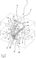
- rotary heat exchanger 1 has an approximately square housing 2 in the illustrated embodiment with respect to its outer contour.
- the housing 2 surrounds a rotor 3 of the rotary heat exchanger 1 at the periphery of the former.
- the rotor 3 has a first flow sector 4, which, as shown FIG. 2 shows, is flowed through by external 5 or supply air 6.
- the air flow for the outside air 5 and the supply air 6 is in FIG. 2 represented by arrows.
- the rotor 3 has a second flow sector 7, which is traversed in the opposite direction to the outside 5 and supply air 6 of Ab-8 and exhaust air 9.
- the by the 8 and the exhaust air 9 formed air flow is in FIG. 2 also represented by arrows.
- the rotor 3 of the rotary heat exchanger is arranged rotatably about a bearing or a hub 10.
- the direction of rotation of the rotor 3 is in FIG. 1 and FIG. 2 shown by the arrow 11.
- the housing 2 is connected to one in the FIGS. 1 and 2 not shown pressure source connected, by means of which the housing 2 is acted upon by housing or sealing air, with a pressure which is higher than the pressure level in the rotor 3 by the flowing air streams 5, 6; 8, 9
- the illustrated by arrows 12, with respect to the rotor 3 radially inwardly extending sealing air flow 12 enters the air stream formed from the outer 5 or supply air 6 and the air flow formed from the exhaust air 8 and 8.
- each circumferential seals 15, 16 are provided, by means of which during operation of the rotary heat exchanger 1 inevitably occurring leaks between the housing 2 on the one hand and the rotor 3 on the other hand should be kept as low as possible.
- peripheral seals 15, 16 are expediently fastened to the front side 13 or to the rear side 14 of the housing 2, so that the outer circumference of the rotor 3 moves with respect to these peripheral seals 15, 16.
- the pressure of the housing or sealing air within the housing 2 is maintained either at a constant pressure level, this pressure level is selected so that it in any case above the pressure level of the rotor 3 by flowing air streams 5, 6; 8, 9 lies.
- an external or an internal pressure source can be provided.
- a control and regulating device By means of a control and regulating device, not shown in the figures, to which a pressure sensor arranged in the housing 2 and a pressure sensor which detects the pressure in the outside 5 or supply air 6 and in the outlet 8 or exhaust air 9 belongs. According to the signals of these pressure sensors, the pressure within the housing 2 is controlled. In this case, as the target size, a target pressure within the housing 2 or a differential pressure between the pressure in the housing 2 and the pressure within the air streams 5, 6; 8, 9 serve.
- the housing 2 with uncritical housing or sealing air is applied.
- said critical air flow can be diluted so as to reduce the risks resulting from the composition of the critical air flow, for example the danger of explosion.
- the two air flow separation devices 19, 20 are quasi formed as center spars, the interior of which is in communication with the interior of the housing 2, so that the two air flow separation means 19, 20 are subjected to pressurized housing or sealing air. From the two air flow separation devices 19, 20 exits a sealing air flow shown by arrows 21, by means of the front surface 17 of the rotor, a mixture of Au- sulfurluft 5 and exhaust air 9 and at the end face 18 of the rotor 3, a mixing of supply air 6 and exhaust. 8 is prevented.
- a Spülkeil insightful 22 is disposed on the end face 17 of the rotor 3 below the air flow separation device 19.
- the flushing wedge device directs a scavenging air flow shown by arrows 23 through the rotating rotor 3, so that Mitrotationsluft from the second flow sector 7, which is associated with the exhaust air 8 and the exhaust air 9 is prevented, in the first flow sector 4 of the rotor 3, the outside air 5 and the supply air 6 is assigned.
- the Spülkeil driving 22 is in the in the FIGS. 1 and 2 shown rotary heat exchanger 1 - as the two air flow separation devices 19, 20 at connected to the housing 2, so that the purge air flow 23 is fed by the housing or sealing air from the housing 2.
- FIGS. 1 and 2 shown rotary heat exchanger 1 equipped with a heater not shown in the figures, by means of which the housing or sealing air can be heated.
- a tempering device by means of which the temperature of the housing or sealing air within the housing 2 can be arbitrarily tempered.
- the above-mentioned heating device is particularly useful if at certain temperature conditions icing of the rotary heat exchanger 1 should be prevented.
- the housing or sealing air can be taken from the supply air system or the outside air system of the rotary heat exchanger 1.
- the housing 2 can with in the FIGS. 1 and 2 Not shown nozzle means may be provided, through which the bearing or the hub 10 of the rotor 3 of the rotary heat exchanger 1 can be kept dry. This is of particular importance in particular in the case of such rotary heat exchangers 1, in which the air streams 5, 6; 8, 9 are moisturized.
Landscapes
- Engineering & Computer Science (AREA)
- Mechanical Engineering (AREA)
- General Engineering & Computer Science (AREA)
- Physics & Mathematics (AREA)
- Thermal Sciences (AREA)
- Chemical & Material Sciences (AREA)
- Combustion & Propulsion (AREA)
- Heat-Exchange Devices With Radiators And Conduit Assemblies (AREA)
- Air Supply (AREA)
Description
- Die Erfindung bezieht sich auf einen Rotationswärmeaustauscher mit einem drehbar gelagerten Rotor, der einen ersten Strömungssektor für Außen- bzw. Zuluft und einen zweiten Strömungssektor für Ab- bzw. Fortluft aufweist, die er bei einer Drehung durchläuft, und einem Gehäuse, das den Rotor an dessen Umfang umgibt, und auf ein Verfahren zur Abdichtung eines derartigen Rotationswärmeaustauschers.
- Bei bekannten derartigen Rotationswärmeaustauschern sind zwischen dem Rotor und dem ihm umgebenden Gehäuse an der vorderen Stirnseite des Rotors und an der hinteren Stirnseite des Rotors Umfangsdichtungen vorgesehen, mittels denen der Austritt von Luft aus den den Rotor durchströmenden Luftströmen in das Gehäuse verhindert werden soll. Da sich der Rotor in Bezug auf das ihn umgebende Gehäuse dreht, treten im Betrieb eines derartigen Rotationswärmeaustauschers stets erhebliche Undichtigkeiten zwischen dem Rotor einerseits und dem Gehäuse andererseits auf, welche dazu führen, dass Luft aus den den Rotor durchströmenden Luftströmen aus dem Rotor austritt. Dies kann dazu führen, dass die von dem Rotationswärmeaustauscher zur Verfügung gestellte Zuluft für einen Raum in unerwünschter Weise verunreinigt wird.
- Ein vergleichbarer Rotationswärmetauscher, gemäß dem Oberbegriff des Anspruchs 1, ist aus der
EP 0 588 185 bekannt. - Der Erfindung liegt die Aufgabe zugrunde, einen Rotationswärmeaustauscher bzw. ein Verfahren zur Abdichtung eines derartigen Rotationswärmeaustauschers derart weiterzubilden, dass solche Leckagen in ungewollter Richtung nicht mehr auftreten können.
- Diese Aufgabe wird erfindungsgemäß dadurch gelöst, dass das den Rotor an dessen Umfang umgebende Gehäuse mit Gehäuse- bzw. Dichtungsluft gefüllt ist, und dass der Druck der Gehäuse- bzw. Dichtungsluft höher als der Druck der den Rotor durchströmenden Luftströme ist. Durch die Beaufschlagung des Gehäuses mit unter Überdruck stehender Gehäuse- bzw. Dichtungsluft wird das Druckniveau im Gehäuse stets oberhalb des Druckniveaus von den den Rotor des Rotationswärmeaustauschers durchströmenden Luftströmen gehalten. Hierdurch kann verhindert werden, dass durch das Gehäuse Außen- bzw. Zuluft mit Ab- bzw. Fortluft vermischt wird.
- Zusätzlich können im Falle des erfindungsgemäßen Rotationswärmeaustauschers selbstverständlich auch Umfangsdichtungen vorgesehen sein, mittels denen der Gehäuse- bzw. Dichtungsluftstrom reduziert werden kann. Derartige Umfangsdichtungen sind vorteilhaft am Gehäuse des Rotationswärmeaustauschers befestigbar.
- Der Druck der Gehäuse- bzw. Dichtungsluft kann auf einem konstanten Druckniveau gehalten werden. Hierbei muss berücksichtigt werden, dass dieses konstante Druckniveau oberhalb des Druckniveaus der den Rotor des Rotationswärmeaustauschers durchströmenden Luftströme liegt.
- Alternativ ist es möglich, den Druck der Gehäuse- bzw. Dichtungsluft um einen konstanten Differenzdruck über dem Druck der den Rotor durchströmenden Luftströme zu halten. Bei dieser Vorgehensweise kann die Menge der Gehäuse- bzw. Dichtungsluft, mittels der das Gehäuse beaufschlagt werden muss, optimiert werden, wobei stets ein ausreichender Überdruck innerhalb des Gehäuses zur Verfügung steht.
- Der Überdruck innerhalb des Gehäuses wird mittels einer externen oder internen Druckquelle erzeugt. Gemäß einer vorteilhaften Ausführungsform gehört zu dem erfindungsgemäßen Rotationswärmeaustauscher eine Steuer- und Regeleinrichtung, mittels der der Betrieb der Druckquelle entsprechend dem Signal eines den Druck im Gehäuse und/oder eines den Druck der den Rotor durchströmenden Luftströme messenden Druckfühlers steuer- bzw. regelbar ist. Entsprechend wird das Druckniveau der Gehäuse- bzw. Dichtungsluft im Gehäuse in Abhängigkeit vom Druckniveau im Gehäuse, dem ein Solldruck zugrunde gelegt wird, und/oder vom Druckniveau der den Rotor durchströmenden Luftströme gesteuert bzw. geregelt. Insbesondere bei solchen Einsatzorten und Anwendungsfällen, bei denen in der Abluft bzw. in der Fortluft Befrachtungen und Zusammensetzungen vorliegen, die z.B. eine Explosionsgefahr hervorrufen können, ist es vorteilhaft, wenn das Gehäuse mit unkritischer Gehäuse- bzw. Dichtungsluft beaufschlagt wird, da dann die kritischen Inhalte der Ab- bzw. Fortluft verdünnt werden können, so dass z.B. in Explosionsbereichen für Antriebsmotoren der Explosionsschutz wegfallen kann.
- Gemäß dem erfindungsgemäßen Rotationswärmetauscher sind an den Stirnflächen des Rotors zwischen den beiden Strömungssektoren diametral verlaufend Luftstromtrennungseinrichtungen angeordnet, die mit dem Gehäuse verbunden und mittels der im Gehäuse vorhandenen Gehäuse- bzw. Dichtungsluft mit Dichtungsluftstrom versorgt werden können. Ein für die Luftstromtrennungseinrichtungen ansonsten erforderlicher Ventilator kann im Falle des erfindungsgemäßen Rotationswärmeaustauschers entfallen. An einer Stirnfläche des Rotors ist in demjenigen Bereich des Strömungssektors für Ab- bzw. Fortluft, der - in Drehrichtung des Rotors - unmittelbar vor dem Strömungssektor für Außen- bzw. Zuluft angeordnet ist, eine Spülkeileinrichtung vorgesehen, die mit dem Gehäuse verbunden und mittels der im Gehäuse vorhandenen Gehäuse- bzw. Dichtungsluft mit Spülluftstrom versorgbar. Auf einen separaten Ventilator zur Versorgung der Spülkeileinrichtung kann verzichtet werden.
- Sofern der erfindungsgemäße Rotationswärmeaustauscher gemäß einer vorteilhaften Weiterbildung mit einer Temperiervorrichtung versehen ist, mittels der die Gehäuse- bzw. Dichtungsluft, z.B. zum Zwecke des Vereisungsschutzes, temperierbar ist, kann jedwede Vereisung der Umfangsdichtungen verhindert werden, wobei darüber hinaus eine Kondensatbildung im Gehäuse ausgeschlossen werden kann. Die Gehäuse- bzw. Dichtungsluft lässt sich in einfacher Weise der Zuluft- und/oder der Außenluftanlage des Rotationswärmeaustauschers entnehmen.
- Vorteilhaft sind am Gehäuse des erfindungsgemäßen Rotationswärmeaustauschers Düseneinrichtungen vorgesehen, durch die hindurch Gehäuse- bzw. Dichtungsluft auf ein Lager des Rotors gerichtet werden kann. Hierdurch kann mit einem vergleichsweise geringen Aufwand das Lager des Rotors trocken gehalten werden.
- Im folgenden wird die Erfindung anhand einer Ausführungsform unter Bezugnahme auf die Zeichnung näher erläutert.
- Es zeigen:
- Figur 1
- eine Ansicht eines erfindungsgemäß ausgebildeten Rotationswärmeaustauschers; und
- Figur 2
- eine prinzipielle Darstellung von einen Rotor des erfindungsgemäßen Rotationswärmeaustauschers durch-strömenden Luftströmen sowie von Dichtungs- und Spülluftströmen bei dem erfindungsgemäß ausgestalteten Rotationswärmeaustauscher.
- Ein in
Figur 1 in perspektivischer Darstellung gezeigter erfindungsgemäßer Rotationswärmeaustauscher 1 hat ein in der dargestellten Ausführungsform hinsichtlich seiner Außenkontur etwa quadratisches Gehäuse 2. - Das Gehäuse 2 umgibt einen Rotor 3 des Rotationswärmeaustauschers 1 am Umfang des ersteren.
- Der Rotor 3 hat einen ersten Strömungssektor 4, der, wie aus
Figur 2 hervorgeht, von Außen- 5 bzw. Zuluft 6 durchströmt wird. Der Luftstrom für die Außenluft 5 und die Zuluft 6 ist inFigur 2 durch Pfeile dargestellt. - Des weiteren besitzt der Rotor 3 einen zweiten Strömungssektor 7, der in Gegenrichtung zur Außen- 5 und Zuluft 6 von Ab-8 und Fortluft 9 durchströmt wird. Der durch die Ab- 8 und die Fortluft 9 gebildete Luftstrom wird in
Figur 2 ebenfalls durch Pfeile dargestellt. - Der Rotor 3 des Rotationswärmeaustauschers ist um ein Lager bzw. eine Nabe 10 drehbar angeordnet. Die Drehrichtung des Rotors 3 wird in
Figur 1 undFigur 2 durch den Pfeil 11 gezeigt. - Das Gehäuse 2 ist an eine in den
Figuren 1 und2 nicht gezeigte Druckquelle angeschlossen, mittels der das Gehäuse 2 mit Gehäuse- bzw. Dichtungsluft beaufschlagt wird, und zwar mit einem Druck, der höher ist, als das Druckniveau in den den Rotor 3 durchströmenden Luftströmen 5, 6; 8, 9. Hierdurch wird ein Austreten von Ab- 8 bzw. Fortluft 9 aus dem Rotor 3 in radial auswärtiger Richtung verhindert. Entsprechend wird auch ein Austreten von Außen- 5 und Zuluft 6 aus dem Rotor 3 in radial auswärtiger Richtung verhindert. Der durch Pfeile 12 dargestellte, in Bezug auf den Rotor 3 radial einwärts verlaufende Dichtungsluftstrom 12 tritt in den aus der Außen-5 bzw. Zuluft 6 gebildeten Luftstrom und den aus der Ab- 8 und Fortluft 9 gebildeten Luftstrom ein. Durch das unter Überdruck stehende Gehäuse 2 wird quasi eine kontrollierte Kammerluftdichtung für den Rotationswärmeaustauscher 1 geschaffen. - Zwischen dem Umfang des Rotors 3 und der den Rotor 3 umgebenden Vorderseite 13 des Gehäuses 2 sowie der entsprechend vorgesehenen Rückseite 14 des Gehäuses 2 sind jeweils Umfangsdichtungen 15, 16 vorgesehen, mittels denen die im Betrieb des Rotationswärmeaustauschers 1 zwangsläufig auftretenden Undichtigkeiten zwischen dem Gehäuse 2 einerseits und dem Rotor 3 andererseits möglichst gering gehalten werden sollen.
- Diese Umfangsdichtungen 15, 16 sind zweckmäßigerweise an der Vorderseite 13 bzw. an der Rückseite 14 des Gehäuses 2 befestigt, so dass sich der Außenumfang des Rotors 3 in Bezug auf diese Umfangsdichtungen 15, 16 bewegt.
- Der Druck der Gehäuse- bzw. Dichtungsluft innerhalb des Gehäuses 2 wird entweder auf einem konstanten Druckniveau gehalten, wobei dieses Druckniveau so gewählt ist, dass es in jedem Fall oberhalb des Druckniveaus der den Rotor 3 durchströmenden Luftströme 5, 6; 8, 9 liegt. Alternativ ist es möglich, den Druck der Gehäuse- bzw. Dichtungsluft innerhalb des Gehäuses 2 so zu steuern bzw. zu regeln, dass dieser Druck immer um einen vorgebbaren Differenzdruck oberhalb des Druckniveaus in den Luftströmen 5, 6; 8, 9 liegt, die den Rotor 3 durchströmen.
- Als Druckquelle kann eine externe oder eine interne Druckquelle vorgesehen sein.
- Mittels einer in den Figuren nicht dargestellten Steuer- und Regelvorrichtung, zu der ein im Gehäuse 2 angeordneter Druckfühler und ein den Druck in der Außen- 5 bzw. Zuluft 6 sowie in der Ab- 8 bzw. Fortluft 9 erfassender Druckfühler gehört. Entsprechend den Signalen dieser Druckfühler wird der Druck innerhalb des Gehäuses 2 gesteuert bzw. geregelt. Hierbei kann als Zielgröße ein Solldruck innerhalb des Gehäuses 2 oder aber ein Differenzdruck zwischen dem Druck im Gehäuse 2 und dem Druck innerhalb der Luftströme 5, 6; 8, 9 dienen.
- Sofern der Rotor 3 des Rotationswärmeaustauschers 1 von zumindest einem hinsichtlich seiner Zusammensetzung kritischen Luftstrom durchströmt wird, ist es zweckmäßig, wenn das Gehäuse 2 mit unkritischer Gehäuse- bzw. Dichtungsluft beaufschlagt wird. Mittels dieser unkritischen Gehäuse- bzw. Dichtungsluft kann der genannte kritische Luftstrom so verdünnt werden, dass aus der Zusammensetzung des kritischen Luftstroms resultierende Gefahren, z.B. Explosionsgefahr, reduziert werden.
- An den beiden Stirnflächen 17, 18 des Rotors 3 ist jeweils eine sich waagerecht und diametral über den Rotor 3 erstreckende Luftstromtrennungseinrichtung 19 bzw. 20 vorgesehen. Die beiden Luftstromtrennungseinrichtungen 19, 20 sind quasi als Mittenholme ausgebildet, deren Innenraum in Verbindung mit dem Innenraum des Gehäuses 2 steht, so dass die beiden Luftstromtrennungseinrichtungen 19, 20 mit unter Überdruck stehender Gehäuse- bzw. Dichtungsluft beaufschlagt werden. Aus den beiden Luftstromtrennungseinrichtungen 19, 20 tritt ein durch Pfeile 21 gezeigter Dichtungsluftstrom aus, mittels dem an der Stirnfläche 17 des Rotors eine Vermischung von Au-ßenluft 5 und Fortluft 9 und an der Stirnfläche 18 des Rotors 3 eine Vermischung von Zuluft 6 und Abluft 8 verhindert wird.
- Darüber hinaus ist an der Stirnfläche 17 des Rotors 3 unterhalb der Luftstromtrennungseinrichtung 19 eine Spülkeileinrichtung 22 angeordnet. Die Spülkeileinrichtung richtet einen durch Pfeile 23 dargestellten Spülluftstrom durch den sich drehenden Rotor 3, so dass verhindert wird, dass Mitrotationsluft aus dem zweiten Strömungssektor 7, der der Abluft 8 und der Fortluft 9 zugeordnet ist, in den ersten Strömungssektor 4 des Rotors 3 gerät, der der Außenluft 5 und der Zuluft 6 zugeordnet ist. Die Spülkeileinrichtung 22 ist bei dem in den
Figuren 1 und2 gezeigten Rotationswärmeaustauscher 1 - wie die beiden Luftstromtrennungseinrichtungen 19, 20 an das Gehäuse 2 angeschlossen, so dass auch der Spülluftstrom 23 durch die Gehäuse- bzw. Dichtungsluft aus dem Gehäuse 2 gespeist wird. - Des weiteren ist der in den
Figuren 1 und2 gezeigte Rotationswärmeaustauscher 1 mit einer in den Figuren nicht gezeigten Heizvorrichtung ausgerüstet, mittels der die Gehäuse- bzw. Dichtungsluft aufgeheizt werden kann. Es kann jedoch bei bestimmten Anforderungen auch zweckmäßig sein, allgemein eine Temperiervorrichtung vorzusehen, mittels der die Temperatur der Gehäuse- bzw. Dichtungsluft innerhalb des Gehäuses 2 beliebig temperiert werden kann. Die vorstehend erwähnte Heizvorrichtung ist insbesondere dann zweckmäßig, wenn bei bestimmten Temperaturverhältnissen eine Vereisung des Rotationswärmeaustauschers 1 verhindert werden soll. - Die Gehäuse- bzw. Dichtungsluft kann der Zuluftanlage oder der Außenluftanlage des Rotationswärmeaustauschers 1 entnommen werden.
- Das Gehäuse 2 kann mit in den
Figuren 1 und2 nicht gezeigten Düseneinrichtungen versehen sein, durch die hindurch das Lager bzw. die Nabe 10 des Rotors 3 des Rotationswärmeaustauschers 1 trocken gehalten werden kann. Dies ist insbesondere bei solchen Rotationswärmeaustauschern 1 von besonderer Bedeutung, bei denen die den Rotor 3 durchströmenden Luftströme 5, 6; 8, 9 feuchtigkeitsbeaufschlagt sind.
Claims (19)
- Rotationswärmeaustauscher, mit einem drehbar gelagerten Rotor (3), der einen ersten Strömungssektor (4) für Außen-(5) bzw. Zuluft (6) und einen zweiten Strömungssektor (7) für Ab- (8) bzw. Fortluft (9) aufweist, die er bei einer Drehung durchläuft, mit einem Gehäuse (2), das den Rotor (3) an dessen Umfang umgibt, wobei das den Rotor (3) an dessen Umfang umgebende Gehäuse (2) mit Gehäuse- bzw. Dichtungsluft gefüllt ist, und mit einer externen oder internen Druckquelle, mittels der ein Überdruck im Gehäuse (2) erzeugbar ist,
wobei der Druck der Gehäuse- bzw. Dichtungsluft höher als der Druck der den Rotor (3) durchströmenden Luftströme (5, 6; 8, 9) ist, wobei der Rotationswärmeaustauscher (1) an den Stirnflächen (17, 18) des Rotors (3) zwischen den beiden Strömungssektoren (4, 7) diametral verlaufend angeordnete Luftstromtrennungseinrichtungen (19, 20) aufweist, und wobei ein Dichtungsluftstrom (21) aus den Luftstromtrennungseinrichtungen (19, 20) austritt und an der Stirnfläche (17) des Rotors (3) eine Vermischung von Außenluft (5) und Fortluft (9) und an der Stirnfläche (18) des Rotors (3) eine Vermischung von Zuluft (6) und Abluft (8) verhindert, wobei die Luftstromtrennungseinrichtungen (19, 20) mit dem Gehäuse (2) verbunden und mittels der im Gehäuse (2) vorhandenen Gehäuse- bzw. Dichtungsluft mit dem Dichtungsluftstrom (21) versorgbar sind, dadurch gekennzeichnet, dass an einer Stirnfläche (17) des Rotors (3) in demjenigen Bereich des Strömungssektors (7) für Ab-(8) bzw. Fortluft (9), der - in Drehrichtung (11) des Rotors (3) - unmittelbar vor dem Strömungssektor (4) für Aussen- (5) bzw. Zuluft (6) angeordnet ist, eine Spülkeileinrichtung (22) vorgesehen ist, die mit dem Gehäuse (2) verbunden und mittels der im Gehäuse (2) vorhandenen Gehäuse- bzw. Dichtungsluft mit Spülluftstrom (23) versorgbar ist. - Rotationswärmeaustauscher nach Anspruch 1, bei dem zwischen dem Umfang des Rotors (3) einerseits und dem Gehäuse (2) andererseits Umfangsdichtungen (15, 16) angeordnet sind.
- Rotationswärmeaustauscher nach Anspruch 2, bei dem die Umfangsdichtungen (15, 16) am Gehäuse (2) befestigt sind.
- Rotationswärmeaustauscher nach einem der Ansprüche 1 bis 3, bei dem der Druck der Gehäuse- bzw. Dichtungsluft auf einem konstanten Druckniveau haltbar ist.
- Rotationswärmeaustauscher nach einem der Ansprüche 1 bis 3, bei dem der Druck der Gehäuse- bzw. Dichtungsluft mit einem konstanten Differenzdruck über dem Druck der den Rotor (3) durchströmenden Luftströme (5, 6; 8, 9) haltbar ist.
- Rotationswärmeaustauscher nach einem der Ansprüche 1 bis 5, mit einer Steuer- und Regelvorrichtung, mittels der der Betrieb der Druckquelle entsprechend dem Signal eines den Druck im Gehäuse (2) und/oder eines den Druck der den Rotor (3) durchströmenden Luftströme (5, 6; 8, 9) messenden Druckfühlers steuer- bzw. regelbar ist.
- Rotationswärmeaustauscher nach einem der Ansprüche 1 bis 6, dessen Gehäuse (2) mit unkritischer Gehäuse- bzw. Dichtungsluft beaufschlagbar ist.
- Rotationswärmeaustauscher nach einem der Ansprüche 1 bis 7, mit einer Temperiervorrichtung, mittels der die Gehäuse- bzw. Dichtungsluft, z.B. zum Zwecke des Vereisungsschutzes, temperierbar ist.
- Rotationswärmeaustauscher nach einem der Ansprüche 1 bis 8, bei dem die Gehäuse- bzw. Dichtungsluft der Zuluft- und/oder der Außenluftanlage des Rotationswärmeaustauschers (1) entnehmbar ist.
- Rotationswärmeaustauscher nach einem der Ansprüche 1 bis 9, bei dem am Gehäuse (2) Düseneinrichtungen vorgesehen sind, durch die hindurch Gehäuse- bzw. Dichtungsluft auf ein Lager (10) des Rotors (3) richtbar ist.
- Verfahren zur Abdichtung eines Rotationswärmeaustauschers (1) nach einem der Ansprüche 1 - 10, bei dem ein einen Rotor (3) des Rotationswärmeaustauschers (1) am Umfang des Rotors (3) umgebendes Gehäuse (2) mit Gehäuse- bzw. Dichtungsluft beaufschlagt, der Druck der Gehäuse- bzw. Dichtungsluft im Gehäuse (2) oberhalb des Druckniveaus von den Rotor (3) des Rotationswärmeaustauschers (1) durchströmenden Luftströmen (5, 6; 8, 9) gehalten wird, ein Dichtungsluftstrom (21) aus an Stirnflächen (17, 18) des Rotors (3) angeordneten Luftstromtrennungseinrichtungen (19, 20) austritt und an der Stirnfläche (17) des Rotors (3) eine Vermischung von Außenluft (5) und Fortluft (9) und an der Stirnfläche (18) des Rotors (3) eine Vermischung von Zuluft (6) und Abluft (8) verhindert, dadurch gekennzeichnet, dass die an den Stirnflächen (17, 18) des Rotors (3) angeordneten Luftstromtrennungseinrichtungen (19, 20) aus dem Gehäuse (2) mit Gehäuse- bzw. Dichtungsluft versorgt werden.
- Verfahren nach Anspruch 11, bei dem das Druckniveau der Gehäuse- bzw. Dichtungsluft im Gehäuse (2) konstant gehalten wird.
- Verfahren nach Anspruch 11, bei dem das Druckniveau der Gehäuse- bzw. Dichtungsluft im Gehäuse (2) um einen konstanten Differenzdruck oberhalb des Druckniveaus der den Rotor (3) durchströmenden Luftströme (5, 6; 8, 9) gehalten wird.
- Verfahren nach einem der Ansprüche 11 bis 13, bei dem das Druckniveau der Gehäuse- bzw. Dichtungsluft im Gehäuse (2) in Abhängigkeit vom Druckniveau im Gehäuse (2) und/oder vom Druckniveau der den Rotor (3) durchströmenden Luftströme (5, 6; 8, 9) gesteuert bzw. geregelt wird.
- Verfahren nach einem der Ansprüche 11 bis 14, bei dem das Gehäuse (2) mit unkritischer Gehäuse- bzw. Dichtungsluft beaufschlagt wird.
- Verfahren nach einem der Ansprüche 11 bis 15, bei dem eine Spülkeileinrichtung (22) des Rotors (3) aus dem Gehäuse (2) mit Gehäuse- bzw. Dichtungsluft als Spülluft versorgt wird.
- Verfahren nach einem der Ansprüche 11 bis 16, bei dem die Gehäuse- bzw. Dichtungsluft temperiert wird.
- Verfahren nach einem der Ansprüche 11 bis 17, bei dem die Gehäuse- bzw. Dichtungsluft der Zuluft- und/oder Außenluftanlage des Rotationswärmeaustauschers (1) entnommen wird.
- Verfahren nach einem der Ansprüche 11 bis 18, bei dem Lager (10) des Rotors (3) von Gehäuse- bzw. Dichtungsluft beaufschlagt werden.
Applications Claiming Priority (2)
| Application Number | Priority Date | Filing Date | Title |
|---|---|---|---|
| DE10327078A DE10327078A1 (de) | 2003-06-13 | 2003-06-13 | Rotationswärmeaustauscher und Verfahren zur Abdichtung eines solchen |
| PCT/EP2004/005416 WO2004111563A1 (de) | 2003-06-13 | 2004-05-19 | Rotationswärmeaustauscher und verfahren zur abdichtung eines solchen |
Publications (2)
| Publication Number | Publication Date |
|---|---|
| EP1634029A1 EP1634029A1 (de) | 2006-03-15 |
| EP1634029B1 true EP1634029B1 (de) | 2017-08-30 |
Family
ID=33482926
Family Applications (1)
| Application Number | Title | Priority Date | Filing Date |
|---|---|---|---|
| EP04733795.1A Expired - Lifetime EP1634029B1 (de) | 2003-06-13 | 2004-05-19 | Rotationswärmeaustauscher und verfahren zur abdichtung eines solchen |
Country Status (7)
| Country | Link |
|---|---|
| US (1) | US7849913B2 (de) |
| EP (1) | EP1634029B1 (de) |
| JP (1) | JP4469848B2 (de) |
| KR (1) | KR101105373B1 (de) |
| CN (1) | CN1802548B (de) |
| DE (1) | DE10327078A1 (de) |
| WO (1) | WO2004111563A1 (de) |
Families Citing this family (14)
| Publication number | Priority date | Publication date | Assignee | Title |
|---|---|---|---|---|
| EP1912033A1 (de) * | 2006-10-12 | 2008-04-16 | Nederlandse Organisatie voor Toegepast-Natuuurwetenschappelijk Onderzoek TNO | Verfahren zur Überwachung eines Feuchtigkeitsgehaltes eines Gases für den Einsatz beim Trocknen eines Produktes |
| US7886986B2 (en) * | 2006-11-08 | 2011-02-15 | Semco Inc. | Building, ventilation system, and recovery device control |
| ES2376538T3 (es) * | 2008-05-30 | 2012-03-14 | Amrona Ag | Dispositivo para minimizar el indeseado desbordamiento de fluido de un primer sector a otro sector y sistema de intercambio de calor con tal dispositivo. |
| US8973649B2 (en) * | 2008-12-23 | 2015-03-10 | Tai-Her Yang | Heat exchange apparatus with a rotating disk and automatic control of heat exchange between two fluid streams by modulation of disk rotating speed and/or flow rate |
| US20100289223A1 (en) * | 2009-05-14 | 2010-11-18 | Birmingham James W | Regenerative heat exchanger and method of reducing gas leakage therein |
| CN102200408B (zh) * | 2011-07-09 | 2012-11-07 | 程爱平 | 回转式气气换热器无泄漏密封系统隔离风幕结构 |
| US9841242B2 (en) * | 2013-06-21 | 2017-12-12 | General Electric Technology Gmbh | Method of air preheating for combustion power plant and systems comprising the same |
| SE539066C2 (sv) * | 2015-06-16 | 2017-04-04 | Fläkt Woods AB | Luftbehandlingsanordning och sätt att kontrollera luftläckage vid luftbehandling |
| DE202015005300U1 (de) | 2015-07-30 | 2015-10-05 | Klingenburg Gmbh | Rotationswärmetauscher |
| CN109414641B (zh) | 2016-03-31 | 2023-11-07 | 英万茨热科技有限公司 | 具有减少热导率的吸附气体分离器 |
| CN109341394A (zh) * | 2018-09-19 | 2019-02-15 | 上海贝辉木业有限公司 | 一种热能回收利用设备 |
| US11609005B2 (en) | 2018-09-28 | 2023-03-21 | Johnson Controls Tyco IP Holdings LLP | Adjustable heat exchanger |
| CA3050503C (en) * | 2019-07-24 | 2020-05-26 | Inline Heat Recovery Inc. | Heat recovery unit |
| CN117916546A (zh) * | 2021-07-20 | 2024-04-19 | 莫罗兹·马克西姆·尼古拉耶维奇 | 自除霜热交换器及其应用方法 |
Family Cites Families (26)
| Publication number | Priority date | Publication date | Assignee | Title |
|---|---|---|---|---|
| US2665120A (en) * | 1950-08-09 | 1954-01-05 | Blomquist Uno Olof | Regenerative heat exchanger |
| DE1085284B (de) * | 1956-03-15 | 1960-07-14 | Babcock & Wilcox Dampfkessel | Umlaufender Regenerativ-Vorwaermer fuer Gas, Luft od. dgl. mit Schlitzduesen |
| US2977096A (en) * | 1958-03-26 | 1961-03-28 | Air Preheater | Rotary regenerative heat exchanger |
| US3122200A (en) * | 1960-05-24 | 1964-02-25 | Koch Jakob | Dynamic sealing means for rotary regenerative heat exchangers |
| DE1133850B (de) * | 1961-02-21 | 1962-07-26 | Kraftanlagen Ag | Nachstellvorrichtung fuer die Sektorenplatten bei umlaufenden Regenerativ-Vorwaermern |
| DE1170106B (de) * | 1962-02-09 | 1964-05-14 | Ver Economiser Werke G M B H | Abdichtung fuer Regenerativ-Lufterhitzer mit umlaufender bandfoermiger Speichermasse |
| US3193336A (en) * | 1962-06-19 | 1965-07-06 | Air Preheater | Cooling arrangement for rotor bearing |
| BE792949A (fr) * | 1971-12-18 | 1973-04-16 | Penny Robert N | Echangeur de chaleur a regeneration rotatif |
| DE2262226A1 (de) * | 1972-12-20 | 1974-07-11 | Maschf Augsburg Nuernberg Ag | Drehspeicherwaermeaustauscher |
| JPS5426929Y2 (de) * | 1975-03-24 | 1979-09-04 | ||
| JPS51128039U (de) * | 1975-04-14 | 1976-10-16 | ||
| JPS51133844A (en) * | 1975-05-14 | 1976-11-19 | Toshiba Corp | Rotary heat exchanger |
| DE2547175A1 (de) * | 1975-10-22 | 1977-05-05 | Daimler Benz Ag | Mittenlagerung der waermetauscherscheibe eines regenerativ-waermetauschers |
| SE401621B (sv) * | 1976-06-16 | 1978-05-22 | Munters Ab Carl | Sett och anordning for rening av stoftforande gaser |
| US4062129A (en) * | 1976-08-02 | 1977-12-13 | Takasago Thermal Engineering Co., Ltd. | Arrangement for preparing hot compressed air of reduced moisture content suitable for use in operation of blast furnace |
| JPS5325958A (en) * | 1976-08-21 | 1978-03-10 | Takasago Thermal Eng Co Lts | High pressure gas dry type dehumidifier |
| JPS57174694A (en) * | 1981-04-20 | 1982-10-27 | Toshiba Corp | Heat exchanger |
| JPS59157486A (ja) * | 1983-02-28 | 1984-09-06 | Baanaa Internatl:Kk | 回転式熱交換器 |
| DE3718196A1 (de) * | 1987-05-29 | 1988-12-15 | Kraftanlagen Ag | Verfahren und einrichtung fuer ein entfernen von vereisungen an umlaufenden regenerativ-waerme- und/oder stofftauschern |
| US5577551A (en) | 1992-09-09 | 1996-11-26 | Apparatebau Rothemuhle Brandt & Kritzler Gmbh | Regenerative heat exchanger and method of operating the same |
| DE4230133A1 (de) * | 1992-09-09 | 1994-03-10 | Rothemuehle Brandt Kritzler | Regenerativ-Wärmetauscher und Verfahren zum Betreiben des Wärmetauschers |
| GB9224823D0 (en) * | 1992-11-26 | 1993-01-13 | Howden Group Plc | Ljungstrom heat exchanger |
| JP3611272B2 (ja) * | 1997-12-19 | 2005-01-19 | 三菱重工業株式会社 | 回転再生式熱交換器 |
| US6004384A (en) | 1998-06-03 | 1999-12-21 | Bry-Air, Inc. | Rotary adsorption apparatus |
| JP3606789B2 (ja) * | 2000-06-14 | 2005-01-05 | 大阪ガスエンジニアリング株式会社 | 蓄熱型脱臭装置 |
| KR101212294B1 (ko) | 2008-01-21 | 2012-12-12 | 삼성전자주식회사 | 화상형성장치 |
-
2003
- 2003-06-13 DE DE10327078A patent/DE10327078A1/de not_active Withdrawn
-
2004
- 2004-05-19 CN CN2004800160575A patent/CN1802548B/zh not_active Expired - Fee Related
- 2004-05-19 JP JP2006515777A patent/JP4469848B2/ja not_active Expired - Fee Related
- 2004-05-19 WO PCT/EP2004/005416 patent/WO2004111563A1/de not_active Ceased
- 2004-05-19 EP EP04733795.1A patent/EP1634029B1/de not_active Expired - Lifetime
- 2004-05-19 KR KR1020057023371A patent/KR101105373B1/ko not_active Expired - Fee Related
- 2004-05-19 US US10/555,402 patent/US7849913B2/en active Active
Non-Patent Citations (1)
| Title |
|---|
| None * |
Also Published As
| Publication number | Publication date |
|---|---|
| JP2006527350A (ja) | 2006-11-30 |
| US20060278364A1 (en) | 2006-12-14 |
| US7849913B2 (en) | 2010-12-14 |
| WO2004111563A1 (de) | 2004-12-23 |
| EP1634029A1 (de) | 2006-03-15 |
| CN1802548A (zh) | 2006-07-12 |
| DE10327078A1 (de) | 2004-12-30 |
| KR20060019570A (ko) | 2006-03-03 |
| CN1802548B (zh) | 2010-05-12 |
| KR101105373B1 (ko) | 2012-01-16 |
| JP4469848B2 (ja) | 2010-06-02 |
Similar Documents
| Publication | Publication Date | Title |
|---|---|---|
| EP1634029A1 (de) | Rotationswärmeaustauscher und verfahren zur abdichtung eines solchen | |
| DE102010014637A1 (de) | Vorrichtung und Verfahren zum Konservieren von Fluidsystemen und Triebwerk | |
| EP1664546A1 (de) | Verdichterreinigung | |
| DE69701405T2 (de) | Kühleinrichtung für eine Turbinenscheibe | |
| DE69906372T2 (de) | Gastrockner | |
| EP1431527B1 (de) | Kühlelement für Gase | |
| DE3629878A1 (de) | Knetmaschine | |
| WO2000015450A1 (de) | Radeinheit für ein kraftfahrzeug mit reifenfüllanlage | |
| EP3839259B1 (de) | Pumpe für mit feststoff belastete flüssigkeit | |
| DE202004020680U1 (de) | Rotationswärmetauscher | |
| EP2520890A1 (de) | Rotationswärmetauscher | |
| DE102010050667A1 (de) | Kühlwasserbeaufschlagtes Aggregat für einen Fahrzeugkühlkreislauf | |
| EP3359282B1 (de) | Trockenmittelpatrone mit verbesserter trocknung und regeneration | |
| DE2414102A1 (de) | Einrichtung zur zerstaeubung einer fluessigen oder pastoesen substanz | |
| EP3401244A1 (de) | Fördern eines förderguts | |
| EP0752515A2 (de) | Lagerkammer-Anordnung für eine Gasturbinen-Welle | |
| DE69312409T2 (de) | Vorrichtung zum Entstauben eines Gasstromes | |
| DE19718283C1 (de) | Zentrifugalpumpe | |
| DE2601192C2 (de) | Dichtung in einer Fördervorrichtung | |
| EP3775569B1 (de) | Radialgebläse | |
| DE102017112584A1 (de) | Hydrodynamische Kupplung | |
| DE102017005480A1 (de) | Fahrmischer und Verfahren zum Kühlen von Frischbeton | |
| DE2634653C2 (de) | Regenerativ-Wärmetauscher mit einer stationären Regenerationkammer | |
| DE2803578C2 (de) | Verfahren zum Erzwingen einer bestimmten Temperaturverteilung in einer Pumpe während des Stillstandes | |
| EP3981497A1 (de) | Aufbereitungsvorrichtung, aufbereitungssystem und verfahren zu einem abscheiden von partikeln aus einem gasförmigen medium |
Legal Events
| Date | Code | Title | Description |
|---|---|---|---|
| PUAI | Public reference made under article 153(3) epc to a published international application that has entered the european phase |
Free format text: ORIGINAL CODE: 0009012 |
|
| 17P | Request for examination filed |
Effective date: 20050921 |
|
| AK | Designated contracting states |
Kind code of ref document: A1 Designated state(s): AT BE BG CH CY CZ DE DK EE ES FI FR GB GR HU IE IT LI LU MC NL PL PT RO SE SI SK TR |
|
| DAX | Request for extension of the european patent (deleted) | ||
| RIN1 | Information on inventor provided before grant (corrected) |
Inventor name: STRUENSEE, NORBERT |
|
| 17Q | First examination report despatched |
Effective date: 20110622 |
|
| GRAP | Despatch of communication of intention to grant a patent |
Free format text: ORIGINAL CODE: EPIDOSNIGR1 |
|
| INTG | Intention to grant announced |
Effective date: 20170403 |
|
| GRAS | Grant fee paid |
Free format text: ORIGINAL CODE: EPIDOSNIGR3 |
|
| GRAA | (expected) grant |
Free format text: ORIGINAL CODE: 0009210 |
|
| AK | Designated contracting states |
Kind code of ref document: B1 Designated state(s): AT BE BG CH CY CZ DE DK EE ES FI FR GB GR HU IE IT LI LU MC NL PL PT RO SE SI SK TR |
|
| REG | Reference to a national code |
Ref country code: GB Ref legal event code: FG4D Free format text: NOT ENGLISH |
|
| REG | Reference to a national code |
Ref country code: CH Ref legal event code: EP |
|
| REG | Reference to a national code |
Ref country code: AT Ref legal event code: REF Ref document number: 923961 Country of ref document: AT Kind code of ref document: T Effective date: 20170915 |
|
| REG | Reference to a national code |
Ref country code: IE Ref legal event code: FG4D Free format text: LANGUAGE OF EP DOCUMENT: GERMAN |
|
| REG | Reference to a national code |
Ref country code: DE Ref legal event code: R096 Ref document number: 502004015579 Country of ref document: DE |
|
| REG | Reference to a national code |
Ref country code: NL Ref legal event code: MP Effective date: 20170830 |
|
| PG25 | Lapsed in a contracting state [announced via postgrant information from national office to epo] |
Ref country code: SE Free format text: LAPSE BECAUSE OF FAILURE TO SUBMIT A TRANSLATION OF THE DESCRIPTION OR TO PAY THE FEE WITHIN THE PRESCRIBED TIME-LIMIT Effective date: 20170830 Ref country code: FI Free format text: LAPSE BECAUSE OF FAILURE TO SUBMIT A TRANSLATION OF THE DESCRIPTION OR TO PAY THE FEE WITHIN THE PRESCRIBED TIME-LIMIT Effective date: 20170830 |
|
| PG25 | Lapsed in a contracting state [announced via postgrant information from national office to epo] |
Ref country code: BG Free format text: LAPSE BECAUSE OF FAILURE TO SUBMIT A TRANSLATION OF THE DESCRIPTION OR TO PAY THE FEE WITHIN THE PRESCRIBED TIME-LIMIT Effective date: 20171130 Ref country code: GR Free format text: LAPSE BECAUSE OF FAILURE TO SUBMIT A TRANSLATION OF THE DESCRIPTION OR TO PAY THE FEE WITHIN THE PRESCRIBED TIME-LIMIT Effective date: 20171201 Ref country code: ES Free format text: LAPSE BECAUSE OF FAILURE TO SUBMIT A TRANSLATION OF THE DESCRIPTION OR TO PAY THE FEE WITHIN THE PRESCRIBED TIME-LIMIT Effective date: 20170830 |
|
| PG25 | Lapsed in a contracting state [announced via postgrant information from national office to epo] |
Ref country code: NL Free format text: LAPSE BECAUSE OF FAILURE TO SUBMIT A TRANSLATION OF THE DESCRIPTION OR TO PAY THE FEE WITHIN THE PRESCRIBED TIME-LIMIT Effective date: 20170830 |
|
| PG25 | Lapsed in a contracting state [announced via postgrant information from national office to epo] |
Ref country code: PL Free format text: LAPSE BECAUSE OF FAILURE TO SUBMIT A TRANSLATION OF THE DESCRIPTION OR TO PAY THE FEE WITHIN THE PRESCRIBED TIME-LIMIT Effective date: 20170830 Ref country code: RO Free format text: LAPSE BECAUSE OF FAILURE TO SUBMIT A TRANSLATION OF THE DESCRIPTION OR TO PAY THE FEE WITHIN THE PRESCRIBED TIME-LIMIT Effective date: 20170830 Ref country code: DK Free format text: LAPSE BECAUSE OF FAILURE TO SUBMIT A TRANSLATION OF THE DESCRIPTION OR TO PAY THE FEE WITHIN THE PRESCRIBED TIME-LIMIT Effective date: 20170830 Ref country code: CZ Free format text: LAPSE BECAUSE OF FAILURE TO SUBMIT A TRANSLATION OF THE DESCRIPTION OR TO PAY THE FEE WITHIN THE PRESCRIBED TIME-LIMIT Effective date: 20170830 |
|
| PG25 | Lapsed in a contracting state [announced via postgrant information from national office to epo] |
Ref country code: EE Free format text: LAPSE BECAUSE OF FAILURE TO SUBMIT A TRANSLATION OF THE DESCRIPTION OR TO PAY THE FEE WITHIN THE PRESCRIBED TIME-LIMIT Effective date: 20170830 Ref country code: SK Free format text: LAPSE BECAUSE OF FAILURE TO SUBMIT A TRANSLATION OF THE DESCRIPTION OR TO PAY THE FEE WITHIN THE PRESCRIBED TIME-LIMIT Effective date: 20170830 Ref country code: IT Free format text: LAPSE BECAUSE OF FAILURE TO SUBMIT A TRANSLATION OF THE DESCRIPTION OR TO PAY THE FEE WITHIN THE PRESCRIBED TIME-LIMIT Effective date: 20170830 |
|
| REG | Reference to a national code |
Ref country code: DE Ref legal event code: R097 Ref document number: 502004015579 Country of ref document: DE |
|
| PLBE | No opposition filed within time limit |
Free format text: ORIGINAL CODE: 0009261 |
|
| STAA | Information on the status of an ep patent application or granted ep patent |
Free format text: STATUS: NO OPPOSITION FILED WITHIN TIME LIMIT |
|
| 26N | No opposition filed |
Effective date: 20180531 |
|
| PG25 | Lapsed in a contracting state [announced via postgrant information from national office to epo] |
Ref country code: SI Free format text: LAPSE BECAUSE OF FAILURE TO SUBMIT A TRANSLATION OF THE DESCRIPTION OR TO PAY THE FEE WITHIN THE PRESCRIBED TIME-LIMIT Effective date: 20170830 |
|
| REG | Reference to a national code |
Ref country code: DE Ref legal event code: R119 Ref document number: 502004015579 Country of ref document: DE |
|
| REG | Reference to a national code |
Ref country code: CH Ref legal event code: PL |
|
| GBPC | Gb: european patent ceased through non-payment of renewal fee |
Effective date: 20180519 |
|
| REG | Reference to a national code |
Ref country code: BE Ref legal event code: MM Effective date: 20180531 |
|
| PG25 | Lapsed in a contracting state [announced via postgrant information from national office to epo] |
Ref country code: MC Free format text: LAPSE BECAUSE OF FAILURE TO SUBMIT A TRANSLATION OF THE DESCRIPTION OR TO PAY THE FEE WITHIN THE PRESCRIBED TIME-LIMIT Effective date: 20170830 |
|
| REG | Reference to a national code |
Ref country code: IE Ref legal event code: MM4A |
|
| PG25 | Lapsed in a contracting state [announced via postgrant information from national office to epo] |
Ref country code: CH Free format text: LAPSE BECAUSE OF NON-PAYMENT OF DUE FEES Effective date: 20180531 Ref country code: LI Free format text: LAPSE BECAUSE OF NON-PAYMENT OF DUE FEES Effective date: 20180531 |
|
| PG25 | Lapsed in a contracting state [announced via postgrant information from national office to epo] |
Ref country code: LU Free format text: LAPSE BECAUSE OF NON-PAYMENT OF DUE FEES Effective date: 20180519 |
|
| PG25 | Lapsed in a contracting state [announced via postgrant information from national office to epo] |
Ref country code: IE Free format text: LAPSE BECAUSE OF NON-PAYMENT OF DUE FEES Effective date: 20180519 Ref country code: GB Free format text: LAPSE BECAUSE OF NON-PAYMENT OF DUE FEES Effective date: 20180519 Ref country code: DE Free format text: LAPSE BECAUSE OF NON-PAYMENT OF DUE FEES Effective date: 20181201 Ref country code: FR Free format text: LAPSE BECAUSE OF NON-PAYMENT OF DUE FEES Effective date: 20180531 |
|
| PG25 | Lapsed in a contracting state [announced via postgrant information from national office to epo] |
Ref country code: BE Free format text: LAPSE BECAUSE OF NON-PAYMENT OF DUE FEES Effective date: 20180531 |
|
| REG | Reference to a national code |
Ref country code: AT Ref legal event code: MM01 Ref document number: 923961 Country of ref document: AT Kind code of ref document: T Effective date: 20180519 |
|
| PG25 | Lapsed in a contracting state [announced via postgrant information from national office to epo] |
Ref country code: AT Free format text: LAPSE BECAUSE OF NON-PAYMENT OF DUE FEES Effective date: 20180519 |
|
| PG25 | Lapsed in a contracting state [announced via postgrant information from national office to epo] |
Ref country code: TR Free format text: LAPSE BECAUSE OF FAILURE TO SUBMIT A TRANSLATION OF THE DESCRIPTION OR TO PAY THE FEE WITHIN THE PRESCRIBED TIME-LIMIT Effective date: 20170830 |
|
| PG25 | Lapsed in a contracting state [announced via postgrant information from national office to epo] |
Ref country code: PT Free format text: LAPSE BECAUSE OF FAILURE TO SUBMIT A TRANSLATION OF THE DESCRIPTION OR TO PAY THE FEE WITHIN THE PRESCRIBED TIME-LIMIT Effective date: 20170830 Ref country code: HU Free format text: LAPSE BECAUSE OF FAILURE TO SUBMIT A TRANSLATION OF THE DESCRIPTION OR TO PAY THE FEE WITHIN THE PRESCRIBED TIME-LIMIT; INVALID AB INITIO Effective date: 20040519 |
|
| PG25 | Lapsed in a contracting state [announced via postgrant information from national office to epo] |
Ref country code: CY Free format text: LAPSE BECAUSE OF FAILURE TO SUBMIT A TRANSLATION OF THE DESCRIPTION OR TO PAY THE FEE WITHIN THE PRESCRIBED TIME-LIMIT Effective date: 20170830 |