EP1633428B1 - A joint for fluid transport lines for medical use - Google Patents
A joint for fluid transport lines for medical use Download PDFInfo
- Publication number
- EP1633428B1 EP1633428B1 EP04735488A EP04735488A EP1633428B1 EP 1633428 B1 EP1633428 B1 EP 1633428B1 EP 04735488 A EP04735488 A EP 04735488A EP 04735488 A EP04735488 A EP 04735488A EP 1633428 B1 EP1633428 B1 EP 1633428B1
- Authority
- EP
- European Patent Office
- Prior art keywords
- line
- circuit
- blood
- fluid
- tubular body
- Prior art date
- Legal status (The legal status is an assumption and is not a legal conclusion. Google has not performed a legal analysis and makes no representation as to the accuracy of the status listed.)
- Expired - Lifetime
Links
- 239000012530 fluid Substances 0.000 title claims abstract description 105
- 239000004020 conductor Substances 0.000 claims abstract description 8
- 239000008280 blood Substances 0.000 claims description 92
- 210000004369 blood Anatomy 0.000 claims description 92
- 238000011282 treatment Methods 0.000 claims description 69
- 238000001802 infusion Methods 0.000 claims description 63
- 239000000463 material Substances 0.000 claims description 28
- 239000004033 plastic Substances 0.000 claims description 19
- 229920003023 plastic Polymers 0.000 claims description 19
- 230000004087 circulation Effects 0.000 claims description 18
- 239000000654 additive Substances 0.000 claims description 13
- 230000000996 additive effect Effects 0.000 claims description 13
- 238000003780 insertion Methods 0.000 claims description 9
- 230000037431 insertion Effects 0.000 claims description 9
- 239000012528 membrane Substances 0.000 claims description 4
- 210000000056 organ Anatomy 0.000 claims description 4
- 238000006467 substitution reaction Methods 0.000 claims 2
- OKTJSMMVPCPJKN-UHFFFAOYSA-N Carbon Chemical compound [C] OKTJSMMVPCPJKN-UHFFFAOYSA-N 0.000 claims 1
- 229910052799 carbon Inorganic materials 0.000 claims 1
- 230000001747 exhibiting effect Effects 0.000 claims 1
- 238000000502 dialysis Methods 0.000 abstract description 24
- 230000002572 peristaltic effect Effects 0.000 abstract description 19
- 239000000203 mixture Substances 0.000 abstract description 6
- 239000006229 carbon black Substances 0.000 abstract description 5
- 230000032258 transport Effects 0.000 description 25
- 239000003978 infusion fluid Substances 0.000 description 11
- 230000008901 benefit Effects 0.000 description 8
- 238000012360 testing method Methods 0.000 description 8
- 239000007924 injection Substances 0.000 description 7
- 238000002347 injection Methods 0.000 description 7
- 238000010586 diagram Methods 0.000 description 6
- 230000002792 vascular Effects 0.000 description 6
- 239000000385 dialysis solution Substances 0.000 description 5
- 238000000034 method Methods 0.000 description 5
- 239000000243 solution Substances 0.000 description 5
- 230000017531 blood circulation Effects 0.000 description 4
- 238000010292 electrical insulation Methods 0.000 description 4
- 230000006870 function Effects 0.000 description 4
- 239000007788 liquid Substances 0.000 description 4
- 230000008569 process Effects 0.000 description 4
- 229920005992 thermoplastic resin Polymers 0.000 description 4
- 238000011144 upstream manufacturing Methods 0.000 description 4
- 208000009304 Acute Kidney Injury Diseases 0.000 description 3
- 229920012485 Plasticized Polyvinyl chloride Polymers 0.000 description 3
- 208000033626 Renal failure acute Diseases 0.000 description 3
- 229910000831 Steel Inorganic materials 0.000 description 3
- 230000002159 abnormal effect Effects 0.000 description 3
- 238000004891 communication Methods 0.000 description 3
- 230000008030 elimination Effects 0.000 description 3
- 238000003379 elimination reaction Methods 0.000 description 3
- 238000001914 filtration Methods 0.000 description 3
- 238000001631 haemodialysis Methods 0.000 description 3
- 238000009533 lab test Methods 0.000 description 3
- 230000033001 locomotion Effects 0.000 description 3
- 230000003068 static effect Effects 0.000 description 3
- 239000010959 steel Substances 0.000 description 3
- 239000000126 substance Substances 0.000 description 3
- 238000002560 therapeutic procedure Methods 0.000 description 3
- FAPWRFPIFSIZLT-UHFFFAOYSA-M Sodium chloride Chemical compound [Na+].[Cl-] FAPWRFPIFSIZLT-UHFFFAOYSA-M 0.000 description 2
- 239000005030 aluminium foil Substances 0.000 description 2
- 239000003146 anticoagulant agent Substances 0.000 description 2
- 229940127219 anticoagulant drug Drugs 0.000 description 2
- 238000010276 construction Methods 0.000 description 2
- JHIVVAPYMSGYDF-UHFFFAOYSA-N cyclohexanone Chemical compound O=C1CCCCC1 JHIVVAPYMSGYDF-UHFFFAOYSA-N 0.000 description 2
- 230000000694 effects Effects 0.000 description 2
- 230000005611 electricity Effects 0.000 description 2
- 239000003292 glue Substances 0.000 description 2
- 238000002615 hemofiltration Methods 0.000 description 2
- 239000012212 insulator Substances 0.000 description 2
- 210000003734 kidney Anatomy 0.000 description 2
- 239000004816 latex Substances 0.000 description 2
- 229920000126 latex Polymers 0.000 description 2
- 238000004519 manufacturing process Methods 0.000 description 2
- 239000002184 metal Substances 0.000 description 2
- 229910052751 metal Inorganic materials 0.000 description 2
- 238000002156 mixing Methods 0.000 description 2
- 229920000915 polyvinyl chloride Polymers 0.000 description 2
- 239000004800 polyvinyl chloride Substances 0.000 description 2
- 230000004044 response Effects 0.000 description 2
- 229920002994 synthetic fiber Polymers 0.000 description 2
- 239000012815 thermoplastic material Substances 0.000 description 2
- 238000000108 ultra-filtration Methods 0.000 description 2
- 206010003658 Atrial Fibrillation Diseases 0.000 description 1
- 206010003662 Atrial flutter Diseases 0.000 description 1
- HTTJABKRGRZYRN-UHFFFAOYSA-N Heparin Chemical compound OC1C(NC(=O)C)C(O)OC(COS(O)(=O)=O)C1OC1C(OS(O)(=O)=O)C(O)C(OC2C(C(OS(O)(=O)=O)C(OC3C(C(O)C(O)C(O3)C(O)=O)OS(O)(=O)=O)C(CO)O2)NS(O)(=O)=O)C(C(O)=O)O1 HTTJABKRGRZYRN-UHFFFAOYSA-N 0.000 description 1
- 206010061216 Infarction Diseases 0.000 description 1
- 229910019142 PO4 Inorganic materials 0.000 description 1
- 208000003251 Pruritus Diseases 0.000 description 1
- 208000001647 Renal Insufficiency Diseases 0.000 description 1
- 230000009471 action Effects 0.000 description 1
- 230000001154 acute effect Effects 0.000 description 1
- 238000004026 adhesive bonding Methods 0.000 description 1
- 230000004075 alteration Effects 0.000 description 1
- 230000004888 barrier function Effects 0.000 description 1
- 239000013060 biological fluid Substances 0.000 description 1
- 230000015572 biosynthetic process Effects 0.000 description 1
- OMWQUXGVXQELIX-UHFFFAOYSA-N bitoscanate Chemical compound S=C=NC1=CC=C(N=C=S)C=C1 OMWQUXGVXQELIX-UHFFFAOYSA-N 0.000 description 1
- 230000036772 blood pressure Effects 0.000 description 1
- 230000000747 cardiac effect Effects 0.000 description 1
- 210000000748 cardiovascular system Anatomy 0.000 description 1
- 230000001684 chronic effect Effects 0.000 description 1
- 208000020832 chronic kidney disease Diseases 0.000 description 1
- 239000011248 coating agent Substances 0.000 description 1
- 238000000576 coating method Methods 0.000 description 1
- 239000002131 composite material Substances 0.000 description 1
- 150000001875 compounds Chemical class 0.000 description 1
- 230000008878 coupling Effects 0.000 description 1
- 238000010168 coupling process Methods 0.000 description 1
- 238000005859 coupling reaction Methods 0.000 description 1
- 239000003989 dielectric material Substances 0.000 description 1
- 239000006185 dispersion Substances 0.000 description 1
- 238000005755 formation reaction Methods 0.000 description 1
- 229960002897 heparin Drugs 0.000 description 1
- 229920000669 heparin Polymers 0.000 description 1
- 238000000338 in vitro Methods 0.000 description 1
- 230000007574 infarction Effects 0.000 description 1
- 238000007914 intraventricular administration Methods 0.000 description 1
- 201000006370 kidney failure Diseases 0.000 description 1
- 230000003902 lesion Effects 0.000 description 1
- 239000000314 lubricant Substances 0.000 description 1
- 229940127554 medical product Drugs 0.000 description 1
- VNWKTOKETHGBQD-UHFFFAOYSA-N methane Chemical compound C VNWKTOKETHGBQD-UHFFFAOYSA-N 0.000 description 1
- 238000012544 monitoring process Methods 0.000 description 1
- 150000003891 oxalate salts Chemical class 0.000 description 1
- 235000021317 phosphate Nutrition 0.000 description 1
- 150000003013 phosphoric acid derivatives Chemical class 0.000 description 1
- 229920000642 polymer Polymers 0.000 description 1
- 238000003825 pressing Methods 0.000 description 1
- 238000005086 pumping Methods 0.000 description 1
- 229910052709 silver Inorganic materials 0.000 description 1
- 239000004332 silver Substances 0.000 description 1
- 239000007787 solid Substances 0.000 description 1
- 230000007480 spreading Effects 0.000 description 1
- 238000003892 spreading Methods 0.000 description 1
- 239000003381 stabilizer Substances 0.000 description 1
- 230000001360 synchronised effect Effects 0.000 description 1
- 229920001169 thermoplastic Polymers 0.000 description 1
- 239000004416 thermosoftening plastic Substances 0.000 description 1
- 238000005303 weighing Methods 0.000 description 1
- 230000036642 wellbeing Effects 0.000 description 1
Images


Classifications
-
- A—HUMAN NECESSITIES
- A61—MEDICAL OR VETERINARY SCIENCE; HYGIENE
- A61M—DEVICES FOR INTRODUCING MEDIA INTO, OR ONTO, THE BODY; DEVICES FOR TRANSDUCING BODY MEDIA OR FOR TAKING MEDIA FROM THE BODY; DEVICES FOR PRODUCING OR ENDING SLEEP OR STUPOR
- A61M39/00—Tubes, tube connectors, tube couplings, valves, access sites or the like, specially adapted for medical use
- A61M39/10—Tube connectors; Tube couplings
-
- A—HUMAN NECESSITIES
- A61—MEDICAL OR VETERINARY SCIENCE; HYGIENE
- A61M—DEVICES FOR INTRODUCING MEDIA INTO, OR ONTO, THE BODY; DEVICES FOR TRANSDUCING BODY MEDIA OR FOR TAKING MEDIA FROM THE BODY; DEVICES FOR PRODUCING OR ENDING SLEEP OR STUPOR
- A61M5/00—Devices for bringing media into the body in a subcutaneous, intra-vascular or intramuscular way; Accessories therefor, e.g. filling or cleaning devices, arm-rests
- A61M5/14—Infusion devices, e.g. infusing by gravity; Blood infusion; Accessories therefor
- A61M5/1414—Hanging-up devices
- A61M5/1418—Clips, separators or the like for supporting tubes or leads
-
- A—HUMAN NECESSITIES
- A61—MEDICAL OR VETERINARY SCIENCE; HYGIENE
- A61M—DEVICES FOR INTRODUCING MEDIA INTO, OR ONTO, THE BODY; DEVICES FOR TRANSDUCING BODY MEDIA OR FOR TAKING MEDIA FROM THE BODY; DEVICES FOR PRODUCING OR ENDING SLEEP OR STUPOR
- A61M1/00—Suction or pumping devices for medical purposes; Devices for carrying-off, for treatment of, or for carrying-over, body-liquids; Drainage systems
- A61M1/14—Dialysis systems; Artificial kidneys; Blood oxygenators ; Reciprocating systems for treatment of body fluids, e.g. single needle systems for hemofiltration or pheresis
- A61M1/16—Dialysis systems; Artificial kidneys; Blood oxygenators ; Reciprocating systems for treatment of body fluids, e.g. single needle systems for hemofiltration or pheresis with membranes
-
- A—HUMAN NECESSITIES
- A61—MEDICAL OR VETERINARY SCIENCE; HYGIENE
- A61M—DEVICES FOR INTRODUCING MEDIA INTO, OR ONTO, THE BODY; DEVICES FOR TRANSDUCING BODY MEDIA OR FOR TAKING MEDIA FROM THE BODY; DEVICES FOR PRODUCING OR ENDING SLEEP OR STUPOR
- A61M2205/00—General characteristics of the apparatus
- A61M2205/02—General characteristics of the apparatus characterised by a particular materials
- A61M2205/0233—Conductive materials, e.g. antistatic coatings for spark prevention
-
- A—HUMAN NECESSITIES
- A61—MEDICAL OR VETERINARY SCIENCE; HYGIENE
- A61M—DEVICES FOR INTRODUCING MEDIA INTO, OR ONTO, THE BODY; DEVICES FOR TRANSDUCING BODY MEDIA OR FOR TAKING MEDIA FROM THE BODY; DEVICES FOR PRODUCING OR ENDING SLEEP OR STUPOR
- A61M2230/00—Measuring parameters of the user
- A61M2230/04—Heartbeat characteristics, e.g. ECG, blood pressure modulation
Definitions
- the invention relates to a joint for fluid transport lines for medical use, to a fluid transport line comprising the joint, to an infusion device comprising the line, to a circuit for extracorporeal blood treatment comprising the line, to a machine for extracorporeal blood treatment which is operatively associable to the circuit, and to an apparatus for extracorporeal treatment of blood comprising the machine and the circuit.
- the invention can be usefully applied in the field of intensive treatment of acute renal insufficiency.
- renal insufficiency both chronic and acute, is treated by extracorporeal dialytic treatment, in which blood is removed from the patient through a withdrawal line (arterial line) of an extracorporeal circuit, is sent to a first chamber (blood chamber) of a device for extracorporeal blood treatment (dialyzer or dialyzer filter, or artificial kidney), and is returned to the patient through a return line (venous line) of the extracorporeal circuit.
- a withdrawal line arterial line
- a device for extracorporeal blood treatment dialyzer or dialyzer filter, or artificial kidney
- the treatment device comprises a second chamber (dialysis chamber) which is separated from the first by a semi-permeable membrane.
- the second chamber has an outlet, fluidly connected to a drainage line for a discharge fluid, and generally also has an inlet, fluidly connected to a supply line of a fresh dialysis fluid.
- one or more infusion lines can be provided, in particular a first infusion line, for supply of a first infusion fluid into the blood withdrawal line upstream of the dialyzer filter (pre-infusion), and a second infusion line, for supply of a second infusion fluid into the blood return line, downstream of the dialyzer filter (post-infusion).
- the extracorporeal circuit is associated to a dialysis machine, which comprises at least one blood pump, in general a peristaltic pump, which is predisposed on the withdrawal line and is for the circulation of the blood.
- a dialysis machine which comprises at least one blood pump, in general a peristaltic pump, which is predisposed on the withdrawal line and is for the circulation of the blood.
- the machine also comprises various other pumps, also usually peristaltic, for the circulation of the various fluids which flow in the other fluid transport lines: a drainage pump for circulating the discharge fluid along the drainage line; a pump for circulation of the fresh dialysis fluid along the supply line to the second chamber of the dialyzer filter; and an infusion pump for each infusion line.
- This interference problem in the ECG is found both in complex apparatus, such as a dialysis machine for intensive treatment, as well as in more simple apparatus, such as an infusion device comprising an infusion line with a peristaltic pump.
- the alteration in the ECG recording can lead to an indistinguishable tracing, or can cause distortions that might be wrongly interpreted and confused with signs of cardiac anomalies.
- a main aim of the present invention is to provide a solution to the above-described problem existing in the prior art.
- a further aim of the invention is to realize a fluid transport line that can be incorporable in a circuit for extracorporeal circulation of blood and/or medical fluids, thanks to which it is possible to eliminate ECG interference that can be traced to the operation of the machine associated to the circuit and which comprises means for circulation of the fluid in the circuit itself.
- a further aim of the invention is to make available a machine for extracorporeal blood treatment, to which an extracorporeal circuit is operatively associable and which includes the above-cited fluid transport line, the functioning of which does not cause disturbances to the patient's ECG.
- a further aim of the invention is to provide an infusion device, in which a medical infusion liquid is placed in circulation along an infusion line by a pump, thanks to which device it is possible to eliminate interferences which disturb the ECG and which are due to the operation of the pump.
- An advantage of the invention is that it offers a simple and economical solution to the above-described problem of ECG artefacts caused by the operation of an apparatus for extracorporeal blood treatment.
- a hose construction having an inside surface defining a passage for conveying fluid under pressure and an electrical conductor disposed along the hose construction and having a pair of opposed terminal ends adapted to be placed in communication with the inside passage for dissipating static electricity caused by fluid flow through the passage.
- a connecting tube for catheters comprising an inner wall of latex or synthetic material having embedded in it a helical wire and having two reinforced end portions connected to the tube by coating the length of the tube with a latex or synthetic material solution which is made electrically conductive by mixing in it a conducting material such as carbon black.
- a device intended to suppress pruritus suffered by patients undergoing haemodialysis consisting of two identical elements which join on the blood circuit of the haemodialyser generator and consisting of a tubing including a frayed aluminium foil electrode and an electrode made of steel, silver or another metal. Each electrode is connected to earth by an electrical circuit insulated from any other electrical circuit.
- the steel electrode captures molecules of oxalates and phosphates by electrostatic attachment and allows the frayed aluminium foil electrode to de-electrify the various blood molecules.
- a device for monitoring the access to the cardiovascular system of a patient undergoing an extracorporeal treatment of blood comprises a voltage generator for generating a potential difference between a part of the machine and a first point of a venous branch of the extracorporeal circuit, connecting the patient to the treatment device; a detector for detecting the value of a quantity that correlates with the electric current along at least one section of the venous branch between the first point and a venous needle fitted at the end of the venous branch and inserted in the vascular system of the patient, and calculating means for comparing the detected value with a reference range.
- a further advantage is that the invention realizes an apparatus for extracorporeal blood treatment which eliminates ECG artefacts and which at the same time responds to the necessary requisites of electrical insulation, thus eliminating any risks involving the patient's well-being.
- a further advantage of the invention is that it provides a solution which does not lead to any problems relating to bio-compatibility.
- a still further advantage of the invention is that it provides a fluid transport line, simple and economical to manufacture, which is easily produced using known production processes.
- the number 1 denotes an apparatus for extracorporeal treatment of blood, in particular a dialysis machine for intensive treatment.
- a blood circuit 2 removes the blood from a patient, through a vascular access of known type and not illustrated, and, via at least one withdrawal line (inlet line or arterial line) 2a transports the blood, for example with continuous flow, to a blood treatment device 3 (or filtration unit, or dialyzer filter, or artificial kidney).
- a blood treatment device 3 or filtration unit, or dialyzer filter, or artificial kidney.
- the blood crosses a first chamber (or blood chamber) of the blood treatment device 3 and, via a return line (or outlet line, or venous line) 2b, the treated blood is returned to the internal vascular system of the patient.
- a return line or outlet line, or venous line
- the withdrawal line 2a is connected, immediately downstream of the blood withdrawal zone, to an auxiliary, pre-infusion line 4.
- a source of secondary fluid 5 (for example a container or bag), supplies the pre-infusion line 4.
- the apparatus comprises means for moving the fluid, in the illustrated example constituted by an auxiliary pre-infusion pump 6 (for example a peristaltic pump), which means for moving the fluid control the flow of secondary fluid injected directly into the blood via the pre-infusion line 4.
- auxiliary pre-infusion pump 6 for example a peristaltic pump
- the source of secondary fluid 5 can supply a suitable biological fluid to effect a pre-infusion, but can also supply an anti-coagulant.
- the blood flows, in a blood circulation direction 7, from the withdrawal line 2a towards the filtration unit, and from the filtration unit flow via the return line 2b back to the patient.
- a blood pressure sensor 8 is predisposed immediately downstream of the auxiliary pre-infusion line 4.
- the apparatus comprises means for moving fluid, i.e. in the particular case at least one blood pump 9 for control and management of the blood flow in the blood circuit 2.
- the blood pump 9 is generally peristaltic.
- a device 10 for administering an anti-coagulant for example a syringe containing appropriate doses of heparin, operates on the withdrawal line 2a downstream of the blood pump 9.
- the blood passes a further pressure sensor 11 which monitors the correct flow into the blood circuit 2.
- the blood enters the blood chamber of the treatment device 3, where, through a semi-permeable membrane, the desired substance, molecular and fluidic exchanges occur.
- the treated blood exits the return line 2b, crossing first a gas separator device (generally air) 12, predisposed to stop and expel any gassy substances or air bubbles present in the blood.
- the separator device 12 is operatively associated with a pressure sensor, of known type and not illustrated, for controlling the pressure in the return line 2b.
- the treated blood outletting from the separator device 12 then crosses an air bubble sensor 13 which checks for absence of these dangerous formations internally of the treated blood.
- intercept element 14 Located downstream of the air bubble sensor 13 an intercept element 14 is located, the function of which is to block, during any alarms, the blood flow towards the patient.
- the treated blood Downstream of the intercept element 14 the treated blood is returned to the patient undergoing therapy.
- a fluid circuit 15 is provided with at least one supply line 15a of a treatment fluid (fresh dialysis fluid), which enters a second chamber (dialysis chamber) of the treatment device 3, and a drainage line 15b outletting from the second chamber 3 of the device.
- a treatment fluid fresh dialysis fluid
- At least one source of treatment fluid 16 is connected to the supply line 15a of the fluid circuit 15 (the source of the treatment fluid 16 can be constituted, for example, by at least one bag containing a dialysis liquid).
- the apparatus 1 comprises means for moving the fluid along the supply line 15a, including at least one supply pump 17 (in the illustrated embodiment a peristaltic pump), for controlling the flow of the treatment fluid coming from the source 16 and for defining a direction of circulation 18.
- at least one supply pump 17 in the illustrated embodiment a peristaltic pump
- a split 19 which divides the fluid circuit 15 into an injection branch 20 and an infusion branch 21.
- the infusion branch 21 is connected to the return branch 2b of the blood circuit 2.
- the infusion branch 21 enables a post-infusion directly into the blood circuit 2, using the treatment fluid coming from the source 16.
- the injection branch 20 takes the treatment fluid directly to an inlet of the second chamber of the treatment device 3.
- a selector switch 22 is predisposed in proximity of the split 19, and is for determining the percentage quantities of treatment fluid flow into the infusion branch 21 and into the injection branch 20.
- the selector switch 22 for example a cam switch or clamp switch, can assume at least a first operative configuration, in which the fluid is allowed to pass into the injection branch 20, and prevents passage into the infusion branch 21, and a second operative configuration, in which it allows passage into the infusion branch 21 and prevents passage into the injection branch 20.
- the selector switch 22 can modulate the quantities of fluid contemporaneously crossing one and the other branches 20 and 21, and can determine, including by programming, the changes in the quantities of fluids which flow in one branch or the other according to predetermined times and treatments.
- the treatment fluid flowing in the injection branch 20 enters the second chamber (dialysis chamber) of the treatment device 3, which second chamber is separated from the first chamber (blood chamber) by the semi-permeable membrane which, as has already been mentioned, enables the correct substance exchanges between the blood and treatment fluid.
- the fluid outletting from the second chamber of the treatment device 3, i.e. the discharge fluid, is transported by the drainage line 15b, also known as the effluent line.
- a pressure sensor 23 is predisposed for controlling the functioning of the drainage line 15b.
- a drainage pump 24 Downstream of the pressure sensor 23 are located means for moving the fluid, for example a drainage pump 24, generally a peristaltic pump, able to control the flow in the drainage line 15b of the fluid circuit 15.
- the discharge fluid crosses a blood leak detector 25 and is eliminated or directed into a container 26 for discharge fluid.
- the apparatus comprises at least one further infusion line 27 which removes an infusion fluid from at least one auxiliary source 28 and, using means for moving fluid, usually a peristaltic infusion pump 29 which controls the flow, sends the fluid directly to the blood circuit 2 return line 2b.
- the infusion liquid can be introduced, as in the illustrated embodiment, directly into the gas separator device 12.
- the infusion branch 21 of the fluid circuit 15 and the infusion line 27 are provided with a common end tract 30 for injection into the blood circuit 2.
- This end tract 30 is located downstream of the infusion pump 29 with respect to an infusion direction 14, and terminates directly in the separator device 12.
- the infusion line 27 comprises at least one pre-infusion branch 32 connected to the withdrawal line 2a of the blood circuit 2.
- a split 33 which divides the infusion line 27 into the pre-infusion branch 32 and a post-infusion branch 34.
- the pre-infusion branch 32 transports the infusion fluid, taken from the container 28, towards the withdrawal line 2a of the blood circuit 2, downstream of the blood pump 9 with respect to the circulation direction 7.
- the post-infusion line 34 is directly connected to the common end tract 30.
- the infusion line 27 is provided with a selector switch 35, predisposed in proximity of the split 33, for determining the percentage quantity of the flow of liquid to be sent into the post-infusion branch 34 and the pre-infusion branch 32.
- the selector switch 35 can assume at least a first operative configuration, in which it allows passage of fluid into the pre-infusion branch 32 and prevents passage of fluid into the post-infusion branch 34, and at least a second operative configuration, in which it allows passage of fluid into the post-infusion branch 34 and prevents passage of fluid into the pre-infusion branch 32.
- the switch 35 can establish the percentage of fluid which must pass into each of the two branches 32 and 34, and can if necessary vary the times according to the treatments to be performed.
- the apparatus 1 comprises a disposable part, usable in general for a single treatment, and a fixed part, which is used a number of times for various treatments on various patients.
- the fixed part is in effect the machine for extracorporeal blood treatment.
- the machine comprises, in general, a machine body which usually bears, on a front surface thereof, the various peristaltic pumps 6, 9, 17, 24 and 29, and also the various sensors, denoted by 8, 11, 13, 23 and 25, and the means for controlling flow, denoted by 14, 22 and 35, and an interfacing system with the operator, which generally comprises a display for entering and reading data.
- the machine body also bears, internally, all of the electronic control circuitry, including a machine command unit.
- the disposable part comprises the treatment device 3 and the blood circuit 2; in the illustrated embodiment, in which the apparatus serves to perform dialysis treatment of the intensive kind, the disposable part also comprises the dialysis circuit 15.
- Substantially the machine integrates all of the instrumentation and apparatus destined to be used more than once, in various treatments, on one or more patients.
- the disposable parts destined to be used only once for each treatment to be performed on a patient, are borne on an integrated module, of known type and not illustrated, of the single-use type, applicable directly on the machine body.
- the operation of the apparatus 1 includes a preliminary part, in which the disposable part is associated to the front surface of the machine body.
- the hydraulic circuit (blood circuit 2 and dialysis circuit 15) and the blood treatment circuit 3 are mounted on the machine in such a way that: the various peristaltic pumps engage the predisposed tracts of tubing (pump segments), which are generally U-shaped; all of the sensors are correctly engaged; and the containers of the various fluids are fluidly coupled to the respective fluid transport lines.
- the blood pump 9 is started up, which starts circulation of the blood in the circuit.
- the machine for extracorporeal blood treatment is automatically started up and controlled by the command unit.
- the apparatus for extracorporeal blood treatment described above is able to perform treatments, in particular intensive treatments, each of which comprises one or more of the following treatments, with predeterminable sequences: pure ultrafiltration, haemofiltration, haemodialysis, haemodiafiltration, plasma exchange.
- 36 denotes a joint for fluid transport lines for medical use, which is made according to the object of the invention.
- the joint 36 is predisposed along the drainage line 15b immediately downstream of the blood treatment device 3, that is, just after the outlet from the second chamber of the device 3 and before the drainage pump 24.
- the joint 36 is located between the pressure sensor 23 and the drainage pump 24. This joint 36 will be described in more detail herein below.
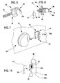
- the joint 36 is illustrated, in a first embodiment, in figure 2 .
- the joint 36 is coupled to the drainage line 15b.
- the joint 36 comprises a tubular body 37, substantially a sleeve-shape, having a cylindrical lateral external side and at two opposite ends two connecting zones 38 and 39, each of which has a cylindrical internal lateral surface for connecting.with an end zone of a usual tubular element 40 of a fluid transport line for medical use.
- the connection gives continuity to fluid passage.
- Each tubular element 40 is a flexible elongate body, with elastically deformable walls, made of a dielectric plastic material, generally a thermoplastic resin, such as for example bio-compatible plasticized PVC.
- the joint 36 is made in a single piece with a relatively small longitudinal extension having more rigid walls than the tubular elements 40.
- the joint 36 is made of a composite material including a mix of plastic material, generally a thermoplastic resin (for example the same material as the tubular elements 40, in this embodiment bio-compatible plasticized PVC), with at least one additive to give it electrical conductivity.
- a thermoplastic resin for example the same material as the tubular elements 40, in this embodiment bio-compatible plasticized PVC
- thermoplastic resins already dielectric, in suitable and known formulas, leads to obtaining a conductive material, though provided with relatively high electrical resistance.
- the additive can be, for example, conductive carbon black, or another known product which, mixed with a thermoplastic resin, transforms the latter from being an insulator to being a conductor.
- the material obtained from a mixture of a plastic material and a conductor additive, can be extruded by usual processes and apparatus used for PVC.
- the selected material for the conductive joint 36 is CABELEC ® 3895, constituted by a compound including carbon black, plasticized PVC, stabilizer and lubricant.
- the two connecting zones 38 and 39 of the joint are designed and structured to join the two tubular elements 40 solidly, one to another (even though axially distanced one from another), giving continuity to fluid passage.
- the two tubular elements 40, joined together by the joint 36, form a single conduit for the passage of a fluid.
- the tubular body 37 made in a single piece, is produced by a plastic material pressing process.
- the tubular body 37 is internally provided with at least one internal surface 41, destined to come into contact with the transported fluid, situated in an intermediate axial zone of the tubular body 37 comprised between the two end connecting zones 38 and 39.
- the external surface of the tubular body 37 is destined to contact electrically with an element which is external of the fluid transport line, with the result that, via for example a grounded connection, the electrical currents present in the transported fluid transported in the fluid transport line can be dissipated.
- the external element illustrated in figures from 6 to 8, will be better described herein below.
- the tubular conductive joint 36 has a greater electrical conductivity than the tubular elements 40 which are reciprocally joined by the joint 36.
- the material of the tubular body 37 is, as has been mentioned, is based on a thermoplastic material, which in itself is dielectric, and which is made electrically conductive thanks to the addition, in the body of the plastic material, of carbon black or another suitable additive for obtaining electrical conductivity.
- the joint 36 can therefore be considered an electrically conductive element, differently to the plastic tubular elements 40, which can be considered electric insulators.
- the conductive joint 36 can be considered a high-resistance electrically-conductive element.
- the electrical impedance between the internal surface and the external surface of the tubular body 37 can vary within a range between 40 K ⁇ and 10 M ⁇ .
- a substantial elimination of electrocardiograph disturbances has been verified, with the ECG connected up to a patient being subjected to extracorporeal treatment, using, in the apparatus, a conductive joint 36 having an electrical impedance variable between 200 K ⁇ and 2 M ⁇ .
- the material and conformation of the joint 36 simply and economically obtain a good, stable, resistant and well-sealed joint, between the jonit 36 and the tubular elements 40 which it joins.
- the joint union permanently stable and unbreakable, can be obtained, during assembly, by a process of known type and already in use, for example, for solid connections by gluing of PVC tubes for medical products having corresponding plastic connectors.
- the procedure involves insertion of the end zones of the tubular elements 40 inside the connecting zones 38 and 39 of the joint 36, with a preliminary spreading on at least one of the coupling surfaces of a certain amount of a suitable glue, for example a cyclo-hexanone-based glue.
- the conductive joint 36' is constituted by a tubular body 37', made in a single piece, which internally comprises at least one first axial stop element 42, operatively associated to an end zone of a first tubular element 40', for limiting an axial insertion of the first tubular element within the tubular body.
- the tubular body 37' internally comprises a second axial stop element 43, axially distanced from the first axial stop element 42, and operatively associated to an end zone of the second tubular element 40", for limiting an axial insertion of the second tubular element inside the tubular body 37', in an opposite direction with respect to the axial insertion of the first tubular element 40'.
- the tubular body 37' has an intermediate zone 41' comprised axially between the two end connecting zones 38' and 39', the internal diameter of which is smaller than the internal diameter of the connecting zones.
- the intermediate zone 41' offers an inwardly-directed annular recess, axially delimited by two abutments, which form the stop elements 42 and 43 which limit insertion of the end zones of the tubular elements 40' and 40".
- the elements 42. and 43 have the function of preventing total covering of the internal surface of the tubular body 37' by the tubular elements 40' and 40", so that a free intermediate zone 41' on the internal surface remains free, i.e. not covered by the end zones of the tubular elements 40' and 40", and in direct contact with the fluid which flows along the fluid transport line. This direct contact allows for dispersion to the outside of any electrostatic charges in the fluid.
- the drainage line 15b of the apparatus 1 is an example of a fluid transport line, for medical use, made according to the invention.
- the fluid transport line comprises at least a first part and a second part, both in contact with the transported fluid, in which the second part is made of a material having a greater electrical conductivity than the material the first part is made of.
- the second part of the line can comprise, as in the embodiment described herein, a conductive joint 36 or 36' like those first described, while the first part can comprise the tubular elements 40, 40', 40" described above.
- the second part of line is also predisposed for galvanic connection to an element which is external of the line, as will be better explained herein below.
- the conductive second part of the line exhibits at least one internal surface destined to contact with the transported fluid, and at least one external surface predisposed to be associated, in electrical contact, with a support element which is external of the line.
- the first part is made of a thermoplastic material which is elastically deformable and dielectric
- the second part is made of a material composed of a mix of thermoplastic, dielectric material with the addition of at least one additive which gives the mixture a certain electrical conductivity.
- the additive also has the property of giving greater rigidity to the mixture.
- the second part of the electrically conductive line is situated, with reference to the fluid transport direction, upstream of a pump segment of the line.
- the pump segment is a tract of line, normally U-shaped and elastically deformable, which is operatively associated to a normally-peristaltic pump, for circulation of the transported fluid.
- the second part of electrically-conductive line can be located, in other embodiments which are not illustrated, in any other point of the hydraulic circuit of figure 1 , either in the fluid circuit 15 (or dialysis circuit) or in the blood circuit 2.
- the location on the drainage line 15b, immediately downstream of the treatment device 3, has the advantage of ensuring an efficient electrical connection between the second part of line (the joint 36) and the blood circuit 2, without resorting to direct contact between the blood and the second part of electrically-conductive line.
- the treatment device 3 does not constitute a barrier to electrical communication between the blood circuit 2 and the fluid circuit 15.
- An apparatus for extracorporeal blood treatment predisposed for cooperating with one of the above-cited hydraulic circuits, comprises at least one support element 44 predisposed to receive, with a mechanical engagement and in electrical contact, the above-mentioned second, electrically-conductive part of line (joint 36 or 36').
- the support element 44 is solidly connected to a front panel 45 of the machine for extracorporeal blood treatment.
- An embodiment of this support element 44 is illustrated in figure 6 , while figures 7 and 8 show the same support element 44 applied to the front panel 45 of the machine (in figure 7 the blood leak detector 25 can also be seen, located by the side of the support element 44).
- the support element 44 comprises at least one electrically-conductive first part 46, made, for example, of metal, fixed to the front panel 45 of the machine by, for example, a screw connection 47.
- the conductive first part 46 can comprise a threaded stalk 48 for the screw connection with the front panel 45.
- the support element 44 further comprises a second part 49, also dielectric and made of a plastic material, provided with a gripping organ 49a for removably fixing the fluid transport line to the conductive second part (the joint).
- the first and second parts 46 and 49 of the support element are solidly constrained one to another, for example by a screw connection (not illustrated).
- the gripping organ 49a comprises, for example, a fastening, in the guise of an elastically deformable hook, which affords a seating in which the conductive joint 36 or 36' can be inserted and held tight in position.
- the joint 36 or 36' can be inserted and and removed manually from the seating.
- the apparatus 1 further comprises a galvanic connection 50 which connects the support element 44 with an external mass, for external dissipation of any electrical charges present in the fluids, corporeal and/or medical, transported in the extracorporeal hydraulic circuit.
- the galvanic connection 50 terminates in the conductive first part 46 of the support element 44.
- the galvanic connection 50 is a true and proper earth for the joint 36, comprising at least one electrical earthing cable which connects the conductive first part of the support element, which is in contact with the above-mentioned conductive second part of line (joint 36 or 36'), with the machine body, which machine body is in turn normally provided with its own grounding.
- the galvanic connection 50 also comprises at least one safety electrical impedance 51, of a predetermined entity, predisposed along the grounding cable between the support element 44 and the machine body.
- This safety impedance 51 guarantees the machine's electrical insulation, as required by the standards, together with the impedance value of the conductive joint 36 or 36'.
- the entity of the electrical impedance 51 can be, for example, above about 0.1 M ⁇ . It has been found that an efficient elimination of ECG artefacts (caused by the action of the peristaltic pumps) is also achieved with a safety impedance 51 of above about 1.0 M ⁇ .
- a plurality of electrical impedances could be predisposed in parallel along the galvanic connection, with the aim of reducing the power dissipated.
- the galvanic connection to earth can comprise, for example, an electronic board having: one or more impedances having predefined characteristics, at least a first contact for connecting to the conductive part 46 of the support element, and at least a second contact for connecting to the earthing cable.
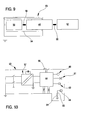
- Figure 9 shows a block diagram of the electical earthing system of the hydraulic circuit of the apparatus 1.
- 52 denotes, in its entirety, the disposable part of the dialysis apparatus, which is provided with at least one conductive element in contact with at least one fluid which is transported along at least one tract of the hydraulic circuit of the apparatus.
- 53 denotes, in its entirety, the fixed part of the dialysis apparatus which comprises the support element 44, which, as mentioned, functions as a mechanical fastening and as an electrical contact for the conductive element of the disposable part.
- 54 denotes the machine body 54 of the machine, which is equipped with it own galvanic earthing connection 55, of known type.
- 56 denotes the electrical connections which connect up the various above-mentioned elements among themselves.
- Figure 10 is a more detailed electrical diagram: 57 denotes the electric supply, 58 the machine command unit, 59 the operator interface display, 60 the entirety of the peristaltic pumps for circulation of the various fluids (corporeal and medical), 61 the entirety of the control organs for regulation of the various fluid transport lines (clamps, valves, selectors etc.), 62 the totality of the sensors (pressure, blood, air-bubble, any fluid-container weighing sensors there might be, and so on).
- the conductive joint 36 or 36' is pressure-fitted, simply and manually, in the seating constituted by the elastic fastening of the support element 44.
- Figures from 11 to 13 show the results of some laboratory tests performed to evaluate the effectiveness of the solution proposed in eliminating the ECG artefacts due to the rotation of the peristaltic pumps.
- an apparatus comprising a machine for dialysis treatment was used, such as the one illustrated in figure 1 , fitted with a disposable integrated module which includes both the blood circuit and the dialysis circuit, and also the dialyzer filter.
- the dialysis circuit used in the tests is the fluid circuit 15 of figure 1 , minus branches 21 and 34.
- a saline solution (9 g/l) was circulated in the blood circuit, taken from a container and returned to the same container; blood pump flow rate was fixed at 180 ml/min.
- terminals L 47K ⁇
- R 380K ⁇
- F 47K ⁇
- N 47K ⁇
- Terminal L was unbalanced by introducing, after the resistance, a 400pF condenser towards the ground.
- the slight unbalance of the impedance of electrode L transforms the common mode voltage produced by the rotation of the pump into a differential signal which is recorded by the ECG on I.
- the conductivity of the conductive joint 36 was measured.
- the joint was filled with saline solution (9 g/l) and the electric resistance between the external surface of the joint and the liquid inside was measured.
- the joint used in the tests had a resistance which varied between 200K ⁇ and 2 MQ.
- Figure 11 which shows the recording obtained with the conductive joint not grounded, evidences the disturbance produced by the pump rotation (paper speed 25 mm/sec, disturbance synchronous with movement of pump at about 6 c/s). There was disturbance on all cutouts with the exception of no. III, where disturbance is rejected and the impedances of the relative electrodes were exactly balanced.
- the automatic interpretation of the tracing gives abnormal ECG with atrial fibrillation, abnormal right axial deviation, unspecific intraventricular blockage.
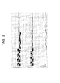
- Figure 12 shows the ECG recording of the same test after the conductive joint, positioned on the effluent line immediately downstream of the dialyzer filter, has been galvanically connected to ground.
- the ground connection consists in connecting the joint by an electric cable to the machine body which in turn is grounded through the supply circuit.
- Figure 13 compares two test recordings.
- the top trace relates to a situation in which the conductive joint was not grounded: the automatic interpretation gives abnormal ECG with atrial flutter, epicardiac lesions, possibility of frontal infarct.
- the bottom trace relates to a situation in which the joint is grounded and in which, along the electric connecting cable between the joint and the body of the machine, a 1.2 M ⁇ resistance has been positioned.
- the automatic response describes an atypical ECG, but none of the negative interpretations given for the top tract.
- the test result is a demonstration of the elimination of the ECG interference, even when a resistance is put in the ground connection which resistance is sufficient to conserve the requisite of electrical insulation of the machine.
- the fluid transport line for medical use comprising the conductive joint 36 or 36', as above described, can be used in the fields various typologies of medical apparatus where ECG interference is a problem.
- the description relates to an apparatus for intensive treatment of acute renal insufficiency: it would be possible however to use the invention in other medical apparatus, such as for example dialysis apparatus for chronic renal insufficiency.
- the device comprises:
- the device can further comprises a safety impedance 68, predisposed along the galvanic connection 67, having the function of guaranteeing that the electrical insulation for the patient undergoing the infusion treatment is in conformity with existing safety standards, and a mechanical fastening and electrical contact element, denoted by 69, to which the conductive joint 66 is applied, for example removably.
- a safety impedance 68 predisposed along the galvanic connection 67, having the function of guaranteeing that the electrical insulation for the patient undergoing the infusion treatment is in conformity with existing safety standards
- a mechanical fastening and electrical contact element denoted by 69, to which the conductive joint 66 is applied, for example removably.
- the infusion line 64 can be connected, directly to a vascular access of the patient, or indirectly to the patient, via an extracorporeal circuit.
- the material the conductive joint 66 is made of is a polymer which has been made conductive thanks to addition and mixing of carbon black or another known additive. As can be observed, in this case too the conductive joint 66 is located upstream of the peristaltic pump 65, with reference to the infusion fluid circulation direction.
- the electrical contact element 69 destined to engage with the conductive joint 66 which can be once more, for example, an elastic fastening, can be solidly constrained to the pump body of the peristaltic pump 65.
- the particular location, before the fluid circulation pump, of the conductive element guarantees reciprocal contact, constantly and in all operative situations, between the transported fluid and the conductive element.
- the transport fluid which is galvanically connected to the outside is, in the first case ( figure 1 ) the discharge fluid in the drainage line of a dialyzer filter, and in the second case ( figure 14 ) the infusion fluid circulating along an infusion line, simple or cooperating with an extracorporeal blood circuit.
- Other transport fluids could, however, be galvanically connected to the outside, such as for example blood, circulating in the withdrawal line or the return line of an extracorporeal circuit, or fresh dialyzing fluid, circulating in the supply line of the dialysis chamber of a dialyzer filter, or the pre-infusion or post-infusion liquid of a dialysis circuit.
Landscapes
- Health & Medical Sciences (AREA)
- Heart & Thoracic Surgery (AREA)
- Animal Behavior & Ethology (AREA)
- General Health & Medical Sciences (AREA)
- Anesthesiology (AREA)
- Biomedical Technology (AREA)
- Hematology (AREA)
- Life Sciences & Earth Sciences (AREA)
- Veterinary Medicine (AREA)
- Engineering & Computer Science (AREA)
- Public Health (AREA)
- Pulmonology (AREA)
- Vascular Medicine (AREA)
- External Artificial Organs (AREA)
- Infusion, Injection, And Reservoir Apparatuses (AREA)
- Materials For Medical Uses (AREA)
Priority Applications (1)
| Application Number | Priority Date | Filing Date | Title |
|---|---|---|---|
| PL04735488T PL1633428T3 (pl) | 2003-06-04 | 2004-05-31 | Złącze przewodów do transportu płynu do użytku medycznego |
Applications Claiming Priority (2)
| Application Number | Priority Date | Filing Date | Title |
|---|---|---|---|
| IT000165A ITMO20030165A1 (it) | 2003-06-04 | 2003-06-04 | Giunto per linee di trasporto fluido ad uso medicale. |
| PCT/IB2004/001777 WO2004108206A1 (en) | 2003-06-04 | 2004-05-31 | A joint for fluid transport lines for medical use |
Publications (2)
| Publication Number | Publication Date |
|---|---|
| EP1633428A1 EP1633428A1 (en) | 2006-03-15 |
| EP1633428B1 true EP1633428B1 (en) | 2011-11-23 |
Family
ID=30012765
Family Applications (1)
| Application Number | Title | Priority Date | Filing Date |
|---|---|---|---|
| EP04735488A Expired - Lifetime EP1633428B1 (en) | 2003-06-04 | 2004-05-31 | A joint for fluid transport lines for medical use |
Country Status (11)
| Country | Link |
|---|---|
| EP (1) | EP1633428B1 (pl) |
| JP (1) | JP4597971B2 (pl) |
| KR (1) | KR101084445B1 (pl) |
| CN (1) | CN100560158C (pl) |
| AT (1) | ATE534428T1 (pl) |
| AU (1) | AU2004244825B2 (pl) |
| CA (1) | CA2524486C (pl) |
| ES (1) | ES2379073T3 (pl) |
| IT (1) | ITMO20030165A1 (pl) |
| PL (1) | PL1633428T3 (pl) |
| WO (1) | WO2004108206A1 (pl) |
Cited By (1)
| Publication number | Priority date | Publication date | Assignee | Title |
|---|---|---|---|---|
| DE102016013334B3 (de) | 2016-11-10 | 2018-04-05 | Fresenius Medical Care Deutschland Gmbh | Medizinisches Gerät mit einem Verbindungsstück für die Herstellung einer Flüssigkeitsverbindung zwischen flüssigkeitsführenden Leitungen |
Families Citing this family (13)
| Publication number | Priority date | Publication date | Assignee | Title |
|---|---|---|---|---|
| US20040254513A1 (en) | 2002-04-10 | 2004-12-16 | Sherwin Shang | Conductive polymer materials and applications thereof including monitoring and providing effective therapy |
| US10155082B2 (en) | 2002-04-10 | 2018-12-18 | Baxter International Inc. | Enhanced signal detection for access disconnection systems |
| US7291123B2 (en) * | 2003-06-04 | 2007-11-06 | Gambro Lundia | Joint for fluid transport lines for medical use |
| DE102006042646B4 (de) | 2006-09-12 | 2008-11-20 | Fresenius Medical Care Deutschland Gmbh | Vorrichtung und Verfahren zur Überwachung eines Zugangs zu einem Patienten, insbesondere eines Gefäßzugangs bei einer extrakorporalen Blutbehandlung |
| EP2195044B1 (en) * | 2007-10-03 | 2011-01-26 | Gambro Lundia AB | Medical apparatus |
| DE102009046406B4 (de) * | 2009-11-04 | 2012-04-26 | Fresenius Medical Care Deutschland Gmbh | Schlauchpumpe |
| US10265025B2 (en) * | 2013-06-25 | 2019-04-23 | Biosense Webster (Israel) Ltd. | Electrocardiogram noise reduction |
| US9504522B2 (en) * | 2013-06-25 | 2016-11-29 | Biosense Webster (Israel) Ltd. | Electrocardiogram noise reduction |
| JP6739144B2 (ja) * | 2014-11-12 | 2020-08-12 | 日機装株式会社 | 帯電防止具 |
| US10512715B2 (en) | 2017-01-12 | 2019-12-24 | Fresenius Medical Care Holdings, Inc. | Electrical plug for a dialysis machine |
| US11801364B2 (en) * | 2017-06-30 | 2023-10-31 | Avectas Limited | Electrospray catheter |
| DE102017009752B4 (de) * | 2017-10-19 | 2025-07-24 | Fresenius Medical Care Deutschland Gmbh | Schaltungsanordnung zur Schutzleiteranbindung an mindestens zwei flussigkeitsführende Leitungen und Verfahren zur Überprüfung einer Schutzleiteranbindung |
| CN115068804A (zh) * | 2022-01-25 | 2022-09-20 | 邢朝阳 | 用于辅助ecmo导管连接的气泡排除装置 |
Family Cites Families (10)
| Publication number | Priority date | Publication date | Assignee | Title |
|---|---|---|---|---|
| GB1033971A (en) * | 1963-04-09 | 1966-06-22 | Willy Ruesch | Connecting tube for catheters and surgical instruments |
| US3580983A (en) * | 1969-12-03 | 1971-05-25 | Nat Catheter Corp | Conductive line tube |
| US4215384A (en) * | 1978-03-09 | 1980-07-29 | Dayco Corporation | Hose construction with electrical conductor for dissipating static electricity and method of making same |
| FR2547504B1 (fr) * | 1983-05-04 | 1987-11-06 | Palemon Jean Georges | Dispositif anti-prurits jetable, monte sur generateur hemodialyseur |
| US5127907A (en) * | 1990-12-06 | 1992-07-07 | Abbott Laboratories | System for eliminating or reducing static electricity in infusion pumping systems |
| DE4137628C1 (pl) * | 1991-11-15 | 1992-12-03 | Fresenius Ag, 6380 Bad Homburg, De | |
| SE9303319D0 (sv) * | 1993-10-11 | 1993-10-11 | Gambro Ab | Sätt att beräkna och/eller styra flöder under en viss tidsperiod genom en peristaltisk pump samt en monitor anpassad för utövning av detta sätt |
| CN1105581C (zh) * | 1995-04-05 | 2003-04-16 | 彭罗民 | 自动血透机 |
| IT1308687B1 (it) * | 1999-12-28 | 2002-01-09 | Gambro Dasco Spa | Metodo e dispositivo di rilevamento dell'accesso al sistemacardivascolare in un trattamento extracorporeo del sangue in una |
| JP2003047653A (ja) * | 2001-05-28 | 2003-02-18 | Terumo Corp | 医療用複合材料、医療用管状体および医療用具 |
-
2003
- 2003-06-04 IT IT000165A patent/ITMO20030165A1/it unknown
-
2004
- 2004-05-31 WO PCT/IB2004/001777 patent/WO2004108206A1/en not_active Ceased
- 2004-05-31 CA CA2524486A patent/CA2524486C/en not_active Expired - Lifetime
- 2004-05-31 CN CNB2004800112711A patent/CN100560158C/zh not_active Expired - Lifetime
- 2004-05-31 JP JP2006508416A patent/JP4597971B2/ja not_active Expired - Lifetime
- 2004-05-31 AT AT04735488T patent/ATE534428T1/de active
- 2004-05-31 ES ES04735488T patent/ES2379073T3/es not_active Expired - Lifetime
- 2004-05-31 EP EP04735488A patent/EP1633428B1/en not_active Expired - Lifetime
- 2004-05-31 AU AU2004244825A patent/AU2004244825B2/en not_active Expired
- 2004-05-31 PL PL04735488T patent/PL1633428T3/pl unknown
- 2004-05-31 KR KR1020057020728A patent/KR101084445B1/ko not_active Expired - Lifetime
Cited By (2)
| Publication number | Priority date | Publication date | Assignee | Title |
|---|---|---|---|---|
| DE102016013334B3 (de) | 2016-11-10 | 2018-04-05 | Fresenius Medical Care Deutschland Gmbh | Medizinisches Gerät mit einem Verbindungsstück für die Herstellung einer Flüssigkeitsverbindung zwischen flüssigkeitsführenden Leitungen |
| US11207513B2 (en) | 2016-11-10 | 2021-12-28 | Fresenius Medical Care Deutschland Gmbh | Connection piece for producing a liquid connection between liquid-conveying lines, and medical appliance with such a connection piece |
Also Published As
| Publication number | Publication date |
|---|---|
| AU2004244825A1 (en) | 2004-12-16 |
| ATE534428T1 (de) | 2011-12-15 |
| ES2379073T3 (es) | 2012-04-20 |
| PL1633428T3 (pl) | 2012-04-30 |
| JP2006526447A (ja) | 2006-11-24 |
| CA2524486C (en) | 2011-08-02 |
| CA2524486A1 (en) | 2004-12-16 |
| ITMO20030165A0 (it) | 2003-06-04 |
| KR20060015718A (ko) | 2006-02-20 |
| JP4597971B2 (ja) | 2010-12-15 |
| EP1633428A1 (en) | 2006-03-15 |
| AU2004244825B2 (en) | 2010-06-17 |
| CN1780660A (zh) | 2006-05-31 |
| WO2004108206A1 (en) | 2004-12-16 |
| KR101084445B1 (ko) | 2011-11-21 |
| CN100560158C (zh) | 2009-11-18 |
| ITMO20030165A1 (it) | 2004-12-05 |
Similar Documents
| Publication | Publication Date | Title |
|---|---|---|
| US7291123B2 (en) | Joint for fluid transport lines for medical use | |
| EP1633428B1 (en) | A joint for fluid transport lines for medical use | |
| US8180443B1 (en) | Device and method for monitoring a patient access, in particular a vascular access in extracorporeal blood treatment | |
| AU2002304312B2 (en) | Blood circuit for a dialysis machine and corresponding dialysis machine | |
| EP1706731B1 (en) | Apparatus for monitoring an access device using an electrode which comprises conductive polymer materials | |
| US6932786B2 (en) | Method and device for monitoring the access to the cardiovascular system of a patient | |
| US8529490B2 (en) | Systems and methods for dialysis access disconnection | |
| EA015441B1 (ru) | Устройство и способ контроля доступа к сосудам пациента в аппарате для гемотерапии | |
| US5360395A (en) | Pump conduit segment having connected, parallel branch line | |
| EP2529768A2 (en) | Enhanced signal detection for access disconnection systems | |
| AU2002304312A1 (en) | Blood circuit for a dialysis machine and corresponding dialysis machine | |
| MXPA06008140A (en) | Conductive polymer materials and applications thereof including monitoring and providing effective therapy |
Legal Events
| Date | Code | Title | Description |
|---|---|---|---|
| PUAI | Public reference made under article 153(3) epc to a published international application that has entered the european phase |
Free format text: ORIGINAL CODE: 0009012 |
|
| 17P | Request for examination filed |
Effective date: 20051122 |
|
| AK | Designated contracting states |
Kind code of ref document: A1 Designated state(s): AT BE BG CH CY CZ DE DK EE ES FI FR GB GR HU IE IT LI LU MC NL PL PT RO SE SI SK TR |
|
| DAX | Request for extension of the european patent (deleted) | ||
| RIN1 | Information on inventor provided before grant (corrected) |
Inventor name: MARCHESI, GIANFRANCO Inventor name: DELNEVO, ANNALISA Inventor name: LIGABUE, ANDREA Inventor name: ZACCARELLI, MASSIMO Inventor name: BARALDI, VINCENZO |
|
| 111Z | Information provided on other rights and legal means of execution |
Free format text: AT BE BG CH CY CZ DE DK EE ES FI FR GB GR HU IE IT LU MC NL PL PT RO SE SI SK TR Effective date: 20081020 |
|
| 17Q | First examination report despatched |
Effective date: 20090515 |
|
| GRAP | Despatch of communication of intention to grant a patent |
Free format text: ORIGINAL CODE: EPIDOSNIGR1 |
|
| RIN1 | Information on inventor provided before grant (corrected) |
Inventor name: MARCHESI, GIANFRANCO Inventor name: LIGABUE, ANDREA Inventor name: ZACCARELLI, MASSIMO Inventor name: BARALDI, VINCENZO Inventor name: DELNEVO, ANNALISA |
|
| GRAS | Grant fee paid |
Free format text: ORIGINAL CODE: EPIDOSNIGR3 |
|
| GRAA | (expected) grant |
Free format text: ORIGINAL CODE: 0009210 |
|
| AK | Designated contracting states |
Kind code of ref document: B1 Designated state(s): AT BE BG CH CY CZ DE DK EE ES FI FR GB GR HU IE IT LI LU MC NL PL PT RO SE SI SK TR |
|
| REG | Reference to a national code |
Ref country code: GB Ref legal event code: FG4D |
|
| REG | Reference to a national code |
Ref country code: CH Ref legal event code: EP |
|
| REG | Reference to a national code |
Ref country code: IE Ref legal event code: FG4D |
|
| REG | Reference to a national code |
Ref country code: DE Ref legal event code: R096 Ref document number: 602004035408 Country of ref document: DE Effective date: 20120119 |
|
| REG | Reference to a national code |
Ref country code: NL Ref legal event code: VDEP Effective date: 20111123 |
|
| REG | Reference to a national code |
Ref country code: ES Ref legal event code: FG2A Ref document number: 2379073 Country of ref document: ES Kind code of ref document: T3 Effective date: 20120420 |
|
| REG | Reference to a national code |
Ref country code: PL Ref legal event code: T3 |
|
| PG25 | Lapsed in a contracting state [announced via postgrant information from national office to epo] |
Ref country code: SE Free format text: LAPSE BECAUSE OF FAILURE TO SUBMIT A TRANSLATION OF THE DESCRIPTION OR TO PAY THE FEE WITHIN THE PRESCRIBED TIME-LIMIT Effective date: 20111123 Ref country code: SI Free format text: LAPSE BECAUSE OF FAILURE TO SUBMIT A TRANSLATION OF THE DESCRIPTION OR TO PAY THE FEE WITHIN THE PRESCRIBED TIME-LIMIT Effective date: 20111123 Ref country code: PT Free format text: LAPSE BECAUSE OF FAILURE TO SUBMIT A TRANSLATION OF THE DESCRIPTION OR TO PAY THE FEE WITHIN THE PRESCRIBED TIME-LIMIT Effective date: 20120323 Ref country code: NL Free format text: LAPSE BECAUSE OF FAILURE TO SUBMIT A TRANSLATION OF THE DESCRIPTION OR TO PAY THE FEE WITHIN THE PRESCRIBED TIME-LIMIT Effective date: 20111123 Ref country code: BE Free format text: LAPSE BECAUSE OF FAILURE TO SUBMIT A TRANSLATION OF THE DESCRIPTION OR TO PAY THE FEE WITHIN THE PRESCRIBED TIME-LIMIT Effective date: 20111123 Ref country code: GR Free format text: LAPSE BECAUSE OF FAILURE TO SUBMIT A TRANSLATION OF THE DESCRIPTION OR TO PAY THE FEE WITHIN THE PRESCRIBED TIME-LIMIT Effective date: 20120224 |
|
| PG25 | Lapsed in a contracting state [announced via postgrant information from national office to epo] |
Ref country code: CY Free format text: LAPSE BECAUSE OF FAILURE TO SUBMIT A TRANSLATION OF THE DESCRIPTION OR TO PAY THE FEE WITHIN THE PRESCRIBED TIME-LIMIT Effective date: 20111123 |
|
| PG25 | Lapsed in a contracting state [announced via postgrant information from national office to epo] |
Ref country code: CZ Free format text: LAPSE BECAUSE OF FAILURE TO SUBMIT A TRANSLATION OF THE DESCRIPTION OR TO PAY THE FEE WITHIN THE PRESCRIBED TIME-LIMIT Effective date: 20111123 Ref country code: EE Free format text: LAPSE BECAUSE OF FAILURE TO SUBMIT A TRANSLATION OF THE DESCRIPTION OR TO PAY THE FEE WITHIN THE PRESCRIBED TIME-LIMIT Effective date: 20111123 Ref country code: BG Free format text: LAPSE BECAUSE OF FAILURE TO SUBMIT A TRANSLATION OF THE DESCRIPTION OR TO PAY THE FEE WITHIN THE PRESCRIBED TIME-LIMIT Effective date: 20120223 Ref country code: DK Free format text: LAPSE BECAUSE OF FAILURE TO SUBMIT A TRANSLATION OF THE DESCRIPTION OR TO PAY THE FEE WITHIN THE PRESCRIBED TIME-LIMIT Effective date: 20111123 Ref country code: SK Free format text: LAPSE BECAUSE OF FAILURE TO SUBMIT A TRANSLATION OF THE DESCRIPTION OR TO PAY THE FEE WITHIN THE PRESCRIBED TIME-LIMIT Effective date: 20111123 |
|
| PG25 | Lapsed in a contracting state [announced via postgrant information from national office to epo] |
Ref country code: RO Free format text: LAPSE BECAUSE OF FAILURE TO SUBMIT A TRANSLATION OF THE DESCRIPTION OR TO PAY THE FEE WITHIN THE PRESCRIBED TIME-LIMIT Effective date: 20111123 |
|
| REG | Reference to a national code |
Ref country code: AT Ref legal event code: MK05 Ref document number: 534428 Country of ref document: AT Kind code of ref document: T Effective date: 20111123 |
|
| PLBE | No opposition filed within time limit |
Free format text: ORIGINAL CODE: 0009261 |
|
| STAA | Information on the status of an ep patent application or granted ep patent |
Free format text: STATUS: NO OPPOSITION FILED WITHIN TIME LIMIT |
|
| 26N | No opposition filed |
Effective date: 20120824 |
|
| REG | Reference to a national code |
Ref country code: DE Ref legal event code: R097 Ref document number: 602004035408 Country of ref document: DE Effective date: 20120824 |
|
| PG25 | Lapsed in a contracting state [announced via postgrant information from national office to epo] |
Ref country code: MC Free format text: LAPSE BECAUSE OF NON-PAYMENT OF DUE FEES Effective date: 20120531 |
|
| REG | Reference to a national code |
Ref country code: CH Ref legal event code: PL |
|
| PG25 | Lapsed in a contracting state [announced via postgrant information from national office to epo] |
Ref country code: LI Free format text: LAPSE BECAUSE OF NON-PAYMENT OF DUE FEES Effective date: 20120531 Ref country code: AT Free format text: LAPSE BECAUSE OF FAILURE TO SUBMIT A TRANSLATION OF THE DESCRIPTION OR TO PAY THE FEE WITHIN THE PRESCRIBED TIME-LIMIT Effective date: 20111123 Ref country code: CH Free format text: LAPSE BECAUSE OF NON-PAYMENT OF DUE FEES Effective date: 20120531 |
|
| REG | Reference to a national code |
Ref country code: IE Ref legal event code: MM4A |
|
| PG25 | Lapsed in a contracting state [announced via postgrant information from national office to epo] |
Ref country code: IE Free format text: LAPSE BECAUSE OF NON-PAYMENT OF DUE FEES Effective date: 20120531 |
|
| PG25 | Lapsed in a contracting state [announced via postgrant information from national office to epo] |
Ref country code: FI Free format text: LAPSE BECAUSE OF FAILURE TO SUBMIT A TRANSLATION OF THE DESCRIPTION OR TO PAY THE FEE WITHIN THE PRESCRIBED TIME-LIMIT Effective date: 20111123 |
|
| PG25 | Lapsed in a contracting state [announced via postgrant information from national office to epo] |
Ref country code: LU Free format text: LAPSE BECAUSE OF NON-PAYMENT OF DUE FEES Effective date: 20120531 |
|
| PG25 | Lapsed in a contracting state [announced via postgrant information from national office to epo] |
Ref country code: HU Free format text: LAPSE BECAUSE OF FAILURE TO SUBMIT A TRANSLATION OF THE DESCRIPTION OR TO PAY THE FEE WITHIN THE PRESCRIBED TIME-LIMIT Effective date: 20040531 |
|
| REG | Reference to a national code |
Ref country code: FR Ref legal event code: PLFP Year of fee payment: 13 |
|
| REG | Reference to a national code |
Ref country code: FR Ref legal event code: PLFP Year of fee payment: 14 |
|
| REG | Reference to a national code |
Ref country code: FR Ref legal event code: PLFP Year of fee payment: 15 |
|
| PGFP | Annual fee paid to national office [announced via postgrant information from national office to epo] |
Ref country code: TR Payment date: 20230322 Year of fee payment: 20 Ref country code: PL Payment date: 20230315 Year of fee payment: 20 Ref country code: IT Payment date: 20230317 Year of fee payment: 20 |
|
| PGFP | Annual fee paid to national office [announced via postgrant information from national office to epo] |
Ref country code: FR Payment date: 20230405 Year of fee payment: 20 Ref country code: ES Payment date: 20230612 Year of fee payment: 20 Ref country code: DE Payment date: 20230414 Year of fee payment: 20 |
|
| PGFP | Annual fee paid to national office [announced via postgrant information from national office to epo] |
Ref country code: GB Payment date: 20230405 Year of fee payment: 20 |
|
| REG | Reference to a national code |
Ref country code: DE Ref legal event code: R071 Ref document number: 602004035408 Country of ref document: DE |
|
| REG | Reference to a national code |
Ref country code: GB Ref legal event code: PE20 Expiry date: 20240530 |
|
| REG | Reference to a national code |
Ref country code: ES Ref legal event code: FD2A Effective date: 20240626 |
|
| PG25 | Lapsed in a contracting state [announced via postgrant information from national office to epo] |
Ref country code: GB Free format text: LAPSE BECAUSE OF EXPIRATION OF PROTECTION Effective date: 20240530 |
|
| PG25 | Lapsed in a contracting state [announced via postgrant information from national office to epo] |
Ref country code: ES Free format text: LAPSE BECAUSE OF EXPIRATION OF PROTECTION Effective date: 20240601 |
|
| PG25 | Lapsed in a contracting state [announced via postgrant information from national office to epo] |
Ref country code: GB Free format text: LAPSE BECAUSE OF EXPIRATION OF PROTECTION Effective date: 20240530 Ref country code: ES Free format text: LAPSE BECAUSE OF EXPIRATION OF PROTECTION Effective date: 20240601 |