EP1632865B1 - Databus interface for a controller and controller with a databus interface - Google Patents
Databus interface for a controller and controller with a databus interface Download PDFInfo
- Publication number
- EP1632865B1 EP1632865B1 EP05106497A EP05106497A EP1632865B1 EP 1632865 B1 EP1632865 B1 EP 1632865B1 EP 05106497 A EP05106497 A EP 05106497A EP 05106497 A EP05106497 A EP 05106497A EP 1632865 B1 EP1632865 B1 EP 1632865B1
- Authority
- EP
- European Patent Office
- Prior art keywords
- data bus
- transmission
- controller
- bus interface
- transceiver
- Prior art date
- Legal status (The legal status is an assumption and is not a legal conclusion. Google has not performed a legal analysis and makes no representation as to the accuracy of the status listed.)
- Not-in-force
Links
- 230000005540 biological transmission Effects 0.000 claims description 30
- 238000004891 communication Methods 0.000 claims description 16
- 230000008901 benefit Effects 0.000 description 8
- 238000012544 monitoring process Methods 0.000 description 5
- 238000012546 transfer Methods 0.000 description 4
- 238000011161 development Methods 0.000 description 3
- 230000002457 bidirectional effect Effects 0.000 description 2
- 230000006855 networking Effects 0.000 description 2
- 238000002485 combustion reaction Methods 0.000 description 1
- 238000004590 computer program Methods 0.000 description 1
- 230000003750 conditioning effect Effects 0.000 description 1
- 238000010276 construction Methods 0.000 description 1
- 230000008878 coupling Effects 0.000 description 1
- 238000010168 coupling process Methods 0.000 description 1
- 238000005859 coupling reaction Methods 0.000 description 1
- 238000013461 design Methods 0.000 description 1
- 230000000694 effects Effects 0.000 description 1
- 238000009472 formulation Methods 0.000 description 1
- 238000004519 manufacturing process Methods 0.000 description 1
- 239000000203 mixture Substances 0.000 description 1
- 230000008520 organization Effects 0.000 description 1
- 230000003071 parasitic effect Effects 0.000 description 1
- 230000001105 regulatory effect Effects 0.000 description 1
- 238000012360 testing method Methods 0.000 description 1
- 230000001960 triggered effect Effects 0.000 description 1
Images

Classifications
-
- G—PHYSICS
- G06—COMPUTING; CALCULATING OR COUNTING
- G06F—ELECTRIC DIGITAL DATA PROCESSING
- G06F13/00—Interconnection of, or transfer of information or other signals between, memories, input/output devices or central processing units
- G06F13/38—Information transfer, e.g. on bus
- G06F13/382—Information transfer, e.g. on bus using universal interface adapter
- G06F13/385—Information transfer, e.g. on bus using universal interface adapter for adaptation of a particular data processing system to different peripheral devices
Definitions
- the present invention relates to a data bus interface for a control unit, in particular for a motor vehicle control unit.
- the invention also relates to a control device, in particular a motor vehicle control device, having a data bus interface for accessing a data bus for communication with at least one other control device via the data bus.
- the interface here is an interface between one or more microprocessors on the one hand and a data bus on the other hand.
- the interface prepares signals from a microprocessor to be transferred via a data bus to another microprocessor according to a selected transmission protocol (eg CAN (Controller Area Network), TTCAN (Time Triggered CAN), MOST (Media Oriented Systems Transport), FlexRay, etc.) before they are injected onto the data bus.
- a transmission protocol eg CAN (Controller Area Network), TTCAN (Time Triggered CAN), MOST (Media Oriented Systems Transport), FlexRay, etc.
- the interface may be part of a control unit, in particular part of a motor vehicle control unit. Then on the Control programs are executed to fulfill a proper control and / or regulation function and they can serve to control and coordinate the communication over the data buses.
- the microcontrollers of the interface merely serve to control and coordinate the communication via the data buses and receive the data to be transmitted from other microcontrollers and only forward the received data.
- at least one control unit can be connected to a data bus. The control units connected to the same data bus can then exchange information with one another via the data bus.
- WO 98/44399 discloses a data bus interface with two microprocessors communicating with each other via a data bus.
- the present invention is based on the object to design a data bus interface of the type mentioned in such a way and further, that it can be used very flexible and is inexpensive to manufacture.
- microprocessors and the transceivers of the data bus interfaces according to the invention are integrated on a common printed circuit board.
- the microprocessors in the form of microcontrollers each have two data bus controllers to increase the communication capability of the interface.
- One of the data bus controllers is used for external communication of the microcontroller with corresponding microcontrollers in other data bus interfaces and the other data bus controller is used for internal communication between the microcontrollers.
- At least one external data bus is provided.
- the at least one data bus is arranged outside the data bus interface.
- Each of the microcontrollers is connected to the at least one external data bus via a common or in each case a separate transceiver unit (transceiver).
- the microcontroller of the data bus interfaces according to the invention are connected to other data bus interfaces or to their microcontrollers and can exchange information with them via the at least one external data bus.
- the microcontrollers are each connected to the transceivers via one of their data bus controllers (the so-called first data bus controller).
- the two transceivers are connected to one and the same external data bus. More specifically, the first data bus controllers of both transceivers are connected to the same data bus. Due to the fact that each data bus controller can manage only a certain number of message objects (so-called message objects), this embodiment of the invention has the advantage that the data bus interface according to the invention for a particular data bus significantly more, in the present case with two Microcontrollers namely exactly twice as many, can manage message objects.
- message objects message objects
- the two transceivers are connected to different external data buses.
- the different data buses can operate at the same or different transmission rates.
- signals are transmitted via the two data buses according to different or the same transmission speeds.
- the data bus interface according to the invention could work, for example, as a so-called gateway.
- the data bus interface can communicate via two data buses, wherein the bidirectional information exchange over the control unit or the data bus interface across both data buses is possible.
- an internal data bus is used which is embodied within the data bus interface and connects the two microcontrollers via their second data bus controllers.
- the microcontrollers can be connected directly to the internal data bus without a transceiver unit, since the distance to be bridged via the internal data bus is relatively low and hardly any disturbances (so-called potential and / or level offset) to those via the internal data bus Interact with data bus transmitted signals.
- the number of different signals transmitted over the internal data bus is relatively small, so that mutual interference of the signals can also be almost eliminated. Overall, therefore, the internal data bus comes out due to its simple and clear topology and the reduced signal traffic in normal operation without transceiver.
- the data exchange via the internal data bus is simple and cost-effective, but still works fast, safe and reliable.
- the internal data bus can be designed, for example, as a CAN data bus.
- the data bus interface can be configured for almost all types of data bus networking of the two computing devices. Due to the flexible capabilities of the data bus interfaces is due to the associated high volumes assume that the interface compared to known interfaces even cost advantages, if not all the functions of the data bus interfaces according to the invention are used, for example, if both microcontroller via a common transceiver are connected to the external data bus and the microcontroller not connected to the external data bus sends and receives data via the internal data bus and the other microcontroller connected to the external data bus. The second transceiver would remain unused.
- the internal data bus comprises two lines which are connected to the two computing devices without transceiver units. More specifically, the two lines are connected directly to one of the data bus controllers (the so-called second data bus controller) of the two computing devices.
- the lines of the internal data bus are connected via open collector outputs (so-called open-collector connections) to the two computing devices.
- the second data bus controller the two microcontrollers of the data bus interface via open collector terminals, to which the internal data bus is connected.
- the two computing devices are connected via push-pull outputs (so-called push-pull connections) to the transceiver units.
- the first data bus controller of the two microcontrollers is connected to the external data bus via the push-pull terminals and a transceiver because a push-pull circuit has fewer asymmetries than an open-collector circuit, allowing signal transfer between the microcontrollers and the International Organization for Standardization (ISO) and CARB (California Air Resources Board) compliant and CARB (with only relatively minor asymmetries) external data bus.
- ISO International Organization for Standardization
- CARB California Air Resources Board
- a first terminal of the two computing devices is connected via an AND gate to a first terminal of one of the two transceiver units.
- the transmitting terminals (TxD1) of the first data bus controller are connected to the AND gate by both microcontrollers.
- the output of the AND gate is routed to a first terminal of the common transceiver.
- the second transceiver of the data bus interface which is not used in this case, can be used for other purposes.
- a second connection of the two computing devices is connected directly to a second connection of the one transceiver unit.
- the receive ports (RxD1) of the first data bus controller of both microcontrollers are directly connected to the second port of the common transceiver. Signals received by the transceiver are thus forwarded to both microcontrollers.
- a first bridge element is arranged parallel to the AND gate between the first terminal of the first computing device and the first terminal of the one transmitting-receiving unit.
- the AND gate By opening and closing the bridge element, the AND gate can be bridged and thus virtually inactivated.
- the transmission terminal of the first data bus controller of the second microcontroller and thus the entire transmission path can be decoupled from the AND gate or from the first transceiver.
- About the first transceiver are only signals of the first Transfer microcontroller to the external data bus.
- the AND gate is preferably not populated.
- the first bridge element and any other switching element and / or at any other point of the circuit of the data bus interfaces are used, provided that the same effect (disconnecting the second computing device of the first transceiver) can be achieved.
- the second connection of the second computing device is connected via a second bridge element to a connection line between the second connection of the first computing device and the second connection of the first transmission-reception unit.
- This bridge element of the receiving path can be interrupted to the second microcontroller and thus the receiving terminal of the first data bus controller of the second microcontroller from the first transceiver or from the external data bus are disconnected.
- the second microcontroller can now access the external data bus either via the internal data bus and the first microcontroller or via the second transceiver.
- closing the first bridge element and opening the second bridge element the second microcontroller is completely decoupled from the first transceiver.
- the position of the bridge elements is configured before the actual series use of the data bus interface. Instead of the second bridge element, any other equally acting switching element can also be used at another location in the circuit.
- the internal data bus is connected via a switching element to one of the two transceiver units, wherein a connection between the internal data bus and the second transceiver unit can be manufactured and interrupted by means of the switching element.
- the switching element is preferably designed as a third bridge element arranged between the two lines of the internal data bus.
- the internal data bus can, for example, be led outwards onto the external data bus during an application phase.
- the internal data bus operate according to the Controller Area Network (CAN) standard. It is also proposed that at least one of the external data buses operate according to the Controller Area Network (CAN) standard. If more than one external data bus is provided, both external data buses preferably operate according to the same standard, for example according to the CAN standard, but if necessary with different data rates. By standardizing the standards for data transmission over the data buses, there is better compatibility, so that, for example, signals from the internal data bus can be routed to the external data bus without much additional effort.
- CAN Controller Area Network
- control unit has an inventive data bus interface.
- the control unit 1 comprises a first computing device 2, which is designed as a microprocessor, and a second computing device 3, which is likewise designed as a microprocessor. On the computing devices 2, 3 computer programs are processed, so that the computing devices 2, 3 can fulfill certain control and / or locking functions.
- a preferred application of the control unit 1 is, for example, the automotive sector.
- the first computing device 2, for example, the control and / or regulation of an internal combustion engine and the second computing device 3 take over the control and / or regulation of a transmission.
- Each of the two computing devices 2, 3 has two separate data bus controllers 4, 5 and 6, 7.
- the first data bus controller 4 of the first computing device 2 comprises a first transmission terminal TxD1 and a first Reception RxD1 on.
- the second data bus controller 5 of the first computing device 2 comprises a second transmission port TxD2 and a second reception port RxD2.
- the connections TxD1 of the first data bus controllers 4, 6 of the two computing devices 2, 3 are designed as push-pull outputs, so-called push-pull connections.
- the two connections TxD2 and RxD2 of the second data bus controllers 5, 7 of the two computing devices 2, 3 are designed as open collector connections, so-called open collector connections.
- the two computing devices 2, 3 communicate with each other via an internal data bus 8.
- the internal data bus 8 comprises a first line 9, which interconnects the transmission connections TxD2 of the second data bus controllers 5, 7 of the two computing devices 2, 3, and a second line 10, which receives the reception connections RxD2 of the second data bus controllers 5, 7 both computing devices 2, 3 interconnects. Due to the relatively short length of the lines 9, 10, the lower transmission speed between the two computing devices 2, 3 via the internal data bus 8 and the almost nonexistent interferers (potential and / or level shifter) can on the use of separate transceiver units (so-called transceiver), via which the computing devices 2, 3 can be connected to the lines 9, 10, are dispensed with.
- the data transmission via the internal data bus 8 takes place according to a specific transmission protocol, for example according to the CAN (Controller Area Network) standard.
- the control unit 1 also comprises two transceiver units (transceivers) 11, 12.
- the transceivers 11, 12 are connected to an external data bus 13, which is designed as a CAN bus with two lines 14, 15 (CAN_H, CAN_L).
- the transceivers 11, 12 are for conditioning signals received from or to be sent over the external data bus 13.
- the two computing devices 2, 3 are connected to the first transceiver 11 such that both computing devices 2, 3 are connected to the external data bus 13 via this one transceiver 11.
- the first transmission connections TxD1 of the first data bus controllers 4, 6 of the two computing devices 2, 3 are routed to the inputs of an AND gate 16.
- the output of the AND gate 16 is fed via a first resistor 17 to a first terminal of the transceiver 11.
- a bridge element 18 is arranged from the first transmission terminal TxD1 of the first data bus controller 4 of the first computing device 2 to the output of the AND gate 16.
- the second terminal of the transceiver 11 is connected via a second resistor 19 to the first receiving terminal RxD1 of the first data bus controller 4 of the first computing device 2 and a second bridge element 20 to the first receiving terminal RxD1 of the first data bus controller 6 of the second computing device 3.
- At the output of the AND gate 16 is a dominant signal level when the first computing device 2 or the second computing device 3 emits a dominant signal level, or when both computing devices 2, 3 emit a dominant signal level. There is no dominant signal level only if both computing devices 2, 3 are inactive. In this respect, therefore, the signals to be transmitted from both computing devices 2, 3 are forwarded via the transceiver 11 to the external data bus 13. Signals received from the data bus 13 are routed via the transceiver 11 to both computing devices 2, 3.
- the first bridge element 18 must be open and the second bridge element 20 must be closed. Since each data bus controller 4 to 7 can only manage a limited number of message objects, so-called message objects, the first embodiment of the inventive control device 1 described has the advantage that the control device 1 has twice the number of message objects on the external data bus 13, since the two data bus controllers 4, 6 can each manage the usual number of messages, that is to say twice as many messages, on the external data bus 13.
- the second computing device 3 it is also conceivable for the second computing device 3 to transmit information to be transmitted via the external data bus 13 first to the first computing device 2 via the internal data bus 8, which then forwards the information to the external data bus 13 via the first transceiver 11 , In this case, the computing device 2 would thus effectively work as a pass-through station.
- a third bridge element 21 arranged between the two lines 9, 10 of the internal data bus 8 must be closed. Both lines 9, 10 of the internal data bus 8 are connected via a pull-up resistor 22 to a supply voltage Vcc, which may be, for example, 1.8 volts, 3.3 volts or 5.0 volts connected.
- signals on lines 9, 10 connected to open collector terminals TxD2 and RxD2 can be set to a high (1.8 volts, 3.3 volts, 5.0 volts or other Tension).
- This purpose is also served by the two pull-up resistors 23 and 24, via which the computing device side terminals of the transceiver 11 are connected to the supply voltage Vcc.
- the second computing device 3 is connected according to a third embodiment via its own transceiver to the external data bus 13.
- the terminals TxD1 and RxD1 of the first data bus controller 6 of the second computing device 3 via a third resistor 25 and a fourth resistor 26, which serve as bridges, connected to the computing device side terminals of the second transceiver 12.
- the internal data bus 8 may be placed on the external data bus 13.
- the two lines 9, 10 of the internal data bus 8 are connected via a fifth resistor 27 and a sixth resistor 28 to the computer-side connections of the second transceiver 12 according to a fourth embodiment.
- the information transfer made via the internal data bus 8 can be monitored and analyzed from outside the control unit 1 via the external data bus 13.
- the third bridge element 21 must be opened.
- An essential part of the control device 1 according to the invention is a data bus interface, which is provided by the two transceivers 11, 12 and those parts of the computing devices 2, 3, which are responsible for the communication with the internal data bus 8 and the external data bus 13.
- the computing devices 2, 3 Apart from these parts for the communication, which together with the required interconnection form the data bus interface, the computing devices 2, 3 also have parts to fulfill their intended control and / or regulating function. For example, these parts operate the control program on the computing devices 2, 3.
- FIG. 2 an inventive control device 1 according to a second preferred embodiment is shown.
- the actual circuit of the data bus interface is identical to the one in FIG. 1 illustrated circuit.
- the control unit 1 in FIG. 2 connected to two different external data buses.
- the first transceiver 11 is connected to a first data bus 13 with the lines 14, 15 (CAN_H, CAN_L).
- the second transceiver 12 is connected to a second external data bus 29 with the lines 30, 31 (CAN_H, CAN_L).
- information is transmitted via both external data buses 13, 29 according to the same transmission protocol, namely the CAN standard.
- the information can be transmitted via the two external data buses 13, 29 with the same or different data transmission rates. All above from the first embodiment of FIG. 1 described embodiments can also in the in FIG. 2 illustrated embodiment can be realized.
- the first computing device 2 transmits and receives data via the first external data bus 13, and the second computing device 3 transmits and receives data via the second external data bus 29.
- the information transmission between the two computing devices 2, 3 can be guided via the internal data bus 8 via the second transceiver 12 to the outside to the second external data bus 29 and monitored via this.
- control unit 1 With the aid of the multifunctional data bus interface according to the invention, a multiplicity of tasks and functionalities can be achieved in the control unit 1:
- the electronic circuit for the internal data bus 8 is a communication of the two computing devices 2, 3 (micro-controller) in the control unit 1 via the internal data bus 8 with transfer rates of up to 500 kBaud possible.
- the data bus 8 is also referred to as an in-house CAN bus or as an ECU-internal CAN bus. If desired, and no connection to ECU terminals 32 of the control unit 1 is created, the data exchange of the two computing devices 2, 3 is completely discrete and outside the control unit 1 is not detected.
- the internal data bus 8 is fully monitorable with appropriate component assembly with external, freely available data bus diagnostic tools. Software developers can thus efficiently verify their software, in particular the exchange of information on the internal data bus 8 perform.
- the internal data bus 8 can be connected to an external control data bus 13 or 29 via the control unit terminals 32. This eliminates the construction of other adapter boards for application purposes.
- the internal data bus 8 is connected to an external data bus 13, 29, for example, with the aim to operate monitoring and communication with other microprocessors in other control devices.
- control unit 1 according to the invention has been described for two computing devices 2, 3 and for two transceivers 11, 12. Of course, it is possible to implement the control device according to the invention with more than two computing devices and with more than two transceivers.
Landscapes
- Engineering & Computer Science (AREA)
- Theoretical Computer Science (AREA)
- Physics & Mathematics (AREA)
- General Engineering & Computer Science (AREA)
- General Physics & Mathematics (AREA)
- Small-Scale Networks (AREA)
- Bus Control (AREA)
- Control Of Electric Motors In General (AREA)
- Multi Processors (AREA)
Abstract
Description
Die vorliegende Erfindung betrifft ein Datenbus-Interface für ein Steuergerät, insbesondere für ein Kraftfahrzeugsteuergerät.The present invention relates to a data bus interface for a control unit, in particular for a motor vehicle control unit.
Die Erfindung betrifft außerdem ein Steuergerät, insbesondere ein Kraftfahrzeugsteuergerät, mit einem Datenbus-Interface zum Zugriff auf einen Datenbus zur Kommunikation mit mindestens einem anderen Steuergerät über den Datenbus.The invention also relates to a control device, in particular a motor vehicle control device, having a data bus interface for accessing a data bus for communication with at least one other control device via the data bus.
Als Interface wird hier eine Schnittstelle zwischen einem oder mehreren Mikroprozessoren einerseits und einem Datenbus andererseits bezeichnet. Das Interface bereitet Signale eines Mikroprozessors, die über einen Datenbus an einen anderen Mikroprozessor übertragen werden sollen, gemäß einem gewählten Übertragungsprotokoll (z. B. CAN (Controller Area Network), TTCAN (Time Triggered CAN), MOST (Media Oriented Systems Transport), FlexRay, etc.) auf, bevor sie auf den Datenbus eingekoppelt werden. Das Interface kann Teil eines Steuergerätes, insbesondere Teil eines Kraftfahrzeugsteuergerätes, sein. Dann können auf den Mikrocontrollern Steuerprogramme zur Erfüllung einer bestimmungsgemäßen Steuerungs- und/oder Regelungsfunktion abgearbeitet werden und sie können zur Steuerung und Koordination der Kommunikation über die Datenbusse dienen. Es ist aber auch denkbar, dass die Mikrocontroller des Interfaces lediglich zur Steuerung und Koordination der Kommunikation über die Datenbusse dienen und die zu übertragenden Daten von anderen Mikrocontrollern erhalten und die erhaltenen Daten nur weiterleiten. Mit Hilfe eines Interfaces kann mindestens ein Steuergerät an einen Datenbus angeschlossen werden. Die an den gleichen Datenbus angeschlossenen Steuergeräte können dann über den Datenbus untereinander Informationen austauschen.The interface here is an interface between one or more microprocessors on the one hand and a data bus on the other hand. The interface prepares signals from a microprocessor to be transferred via a data bus to another microprocessor according to a selected transmission protocol (eg CAN (Controller Area Network), TTCAN (Time Triggered CAN), MOST (Media Oriented Systems Transport), FlexRay, etc.) before they are injected onto the data bus. The interface may be part of a control unit, in particular part of a motor vehicle control unit. Then on the Control programs are executed to fulfill a proper control and / or regulation function and they can serve to control and coordinate the communication over the data buses. However, it is also conceivable that the microcontrollers of the interface merely serve to control and coordinate the communication via the data buses and receive the data to be transmitted from other microcontrollers and only forward the received data. With the aid of an interface, at least one control unit can be connected to a data bus. The control units connected to the same data bus can then exchange information with one another via the data bus.
Aus dem Stand der Technik ist es an sich bekannt, in einem CAN-Interface nicht nur einen, sondern zwei oder noch mehr Rechengeräte, insbesondere Mikroprozessoren, in Form von Mikrocontrollern vorzusehen. Dabei werden in der Regel jedoch nur solche Mikroprozessoren in einem CAN-Interface miteinander kombiniert, die lediglich einen CAN-Controller aufweisen. An sich bekannt sind jedoch auch Mikrocontroller mit mehr als einem, beispielsweise zwei, CAN-Controllern. Somit ist aus dem Stand der Technik zum einen ein CAN-Interface mit mehreren Mikrocontrollern bekannt. Zum anderen ist ein CAN-Interface bekannt, das lediglich einen Mikrocontroller, jedoch mit mehreren CAN-Controllern umfasst.From the state of the art it is known per se to provide not only one, but two or even more computing devices, in particular microprocessors, in the form of microcontrollers in a CAN interface. As a rule, however, only such microprocessors are combined with one another in a CAN interface, which only have one CAN controller. However, microcontrollers with more than one, for example two, CAN controllers are also known per se. Thus, a CAN interface with several microcontrollers is known from the prior art on the one hand. On the other hand, a CAN interface is known which comprises only one microcontroller, but with several CAN controllers.
Nach dem Stand der Technik erfolgt in einem CAN-Interface mit mehreren Mikrocontrollern die interne Kommunikation zwischen den einzelnen Controllern über ein Dual-Port-RAM (Random Access Memory). Diese sind jedoch sehr teuer und benötigen viel Energie. Insbesondere im Kraftfahrzeugbereich herrscht ein enormer Kostendruck und steht Energie nicht in unbegrenztem Umfang zur Verfügung.In the prior art, the internal communication between the individual controllers via a dual-port RAM (Random Access Memory) takes place in a CAN interface with multiple microcontrollers. These are very expensive and require a lot of energy. Especially in the automotive sector, there is enormous cost pressure and energy is not available to an unlimited extent.
Der Einsatz von Dual-Port-RAMs zur Kommunikation zwischen den Mikroprozessoren eines Mehrprozessorsystems ist also für Kraftfahrzeuge nicht besonders gut geeignet.The use of dual-port RAMs for communication between the microprocessors of a multiprocessor system is thus not particularly well suited for motor vehicles.
Das Dokument
Der vorliegenden Erfindung liegt die Aufgabe zu Grunde, ein Datenbus-Interface der eingangs genannten Art dahingehend auszugestalten und weiterzubilden, dass es besonders flexibel eingesetzt werden kann und kostengünstig in der Herstellung ist.The present invention is based on the object to design a data bus interface of the type mentioned in such a way and further, that it can be used very flexible and is inexpensive to manufacture.
Zur Lösung dieser Aufgabe wird ausgehend von dem Datenbus-Interface der eingangs genannten Art vorgeschlagen, dass das Interface nach Anspruch 1.To solve this problem is proposed starting from the data bus interface of the type mentioned that the interface of claim 1.
Sowohl die Mikroprozessoren als auch die Transceiver des erfindungsgemäßen Datenbus-Interfaces sind auf einem gemeinsamen Leiterplatte integriert. Die Mikroprozessoren in Form von Mikrocontrollern verfügen jeweils über zwei Datenbus-Controller, um die Kommunikationsfähigkeit des Interfaces zu erhöhen. Einer der Datenbus-Controller dient zur externen Kommunikation der Mikrocontroller mit entsprechenden Mikrocontrollern in anderen Datenbus-Interfaces und der andere Datenbus-Controller wird zur internen Kommunikation zwischen den Mikrocontrollern eingesetzt.Both the microprocessors and the transceivers of the data bus interfaces according to the invention are integrated on a common printed circuit board. The microprocessors in the form of microcontrollers each have two data bus controllers to increase the communication capability of the interface. One of the data bus controllers is used for external communication of the microcontroller with corresponding microcontrollers in other data bus interfaces and the other data bus controller is used for internal communication between the microcontrollers.
Für die externe Datenkommunikation ist mindestens ein externer Datenbus vorgesehen. Der mindestens eine Datenbus ist außerhalb des Datenbus-Interfaces angeordnet. Jeder der Mikrocontroller ist über eine gemeinsame oder jeweils eine eigene Sende-Empfangs-Einheit (Transceiver) an dem mindestens einen externen Datenbus angeschlossen. Über den externen Datenbus sind die Mikrocontroller des erfindungsgemäßen Datenbus-Interfaces mit anderen Datenbus-Interfaces bzw. mit deren Mikrocontroller verbunden und können mit diesen über den mindestens einen externen Datenbus Informationen austauschen. Die Mikrocontroller sind jeweils über einen ihrer Datenbus-Controller (den sogenannten ersten Datenbus-Controller) an die Transceiver angeschlossen.For external data communication at least one external data bus is provided. The at least one data bus is arranged outside the data bus interface. Each of the microcontrollers is connected to the at least one external data bus via a common or in each case a separate transceiver unit (transceiver). Via the external data bus, the microcontroller of the data bus interfaces according to the invention are connected to other data bus interfaces or to their microcontrollers and can exchange information with them via the at least one external data bus. The microcontrollers are each connected to the transceivers via one of their data bus controllers (the so-called first data bus controller).
Es ist denkbar, dass die beiden Transceiver an ein und denselben externen Datenbus angeschlossen sind. Genauer gesagt, sind die ersten Datenbus-Controller von beiden Transceivern an den gleichen Datenbus angeschlossen. Aufgrund der Tatsache, dass jeder Datenbus-Controller nur eine bestimmte Anzahl an Nachrichtenobjekten (sogenannte Message Objects) verwalten kann, hat diese Ausgestaltung der Erfindung den Vorteil, dass das erfindungsgemäße Datenbus-Interface für einen bestimmten Datenbus deutlich mehr, in dem vorliegenden Fall mit zwei Mikrocontrollern nämlich genau doppelt so viele, Nachrichtenobjekte verwalten kann.It is conceivable that the two transceivers are connected to one and the same external data bus. More specifically, the first data bus controllers of both transceivers are connected to the same data bus. Due to the fact that each data bus controller can manage only a certain number of message objects (so-called message objects), this embodiment of the invention has the advantage that the data bus interface according to the invention for a particular data bus significantly more, in the present case with two Microcontrollers namely exactly twice as many, can manage message objects.
Alternativ wird vorgeschlagen, dass die beiden Transceiver an unterschiedlichen externen Datenbussen angeschlossen sind. Mit anderen Worten ist der erste Datenbus-Controller des ersten Mikrocontrollers über den ersten Transceiver an einen ersten externen Datenbus und der erste Datenbus-Controller des zweiten Mikrocontrollers über den zweiten Transceiver an einen zweiten externen Datenbus angeschlossen. Die unterschiedlichen Datenbusse können mit der gleichen oder mit unterschiedlichen Übertragungsraten arbeiten. Des weiteren ist es denkbar, dass über die beiden Datenbusse Signale nach unterschiedlichen oder den gleichen Übertragungsgeschwindigkeiten übertragen werden. Gemäß dieser alternativen Ausgestaltung könnte das erfindungsgemäße Datenbus-Interface beispielsweise als ein sogenanntes Gateway arbeiten. Damit kann das Datenbus-Interface über zwei Datenbusse kommunizieren, wobei der bidirektionale Informationsaustausch über das Steuergerät bzw. das Datenbus-Interface hinweg in beide Datenbusse möglich ist.Alternatively, it is proposed that the two transceivers are connected to different external data buses. In other words, the first data bus controller of the first microcontroller via the first transceiver to a first external data bus and the first data bus controller of the second microcontroller connected via the second transceiver to a second external data bus. The different data buses can operate at the same or different transmission rates. Furthermore, it is conceivable that signals are transmitted via the two data buses according to different or the same transmission speeds. According to this alternative embodiment, the data bus interface according to the invention could work, for example, as a so-called gateway. Thus, the data bus interface can communicate via two data buses, wherein the bidirectional information exchange over the control unit or the data bus interface across both data buses is possible.
Zur internen Kommunikation wird ein interner Datenbus eingesetzt, der innerhalb des Datenbus-Interfaces ausgebildet ist und die beiden Mikrocontroller über ihre zweiten Datenbus-Controller miteinander verbindet. Die Mikrocontroller können ohne eine Sende-Empfangs-Einheit (Transceiver) direkt an den internen Datenbus angeschlossen werden, da die über den internen Datenbus zu überbrückende Entfernung relativ gering ist und kaum Störungen (sogenannter Potential- und/oder Pegelversatz) auf die über den internen Datenbus übertragenen Signale einwirken. Außerdem ist die Anzahl der über den internen Datenbus übertragenen verschiedenen Signale relativ gering, so dass eine wechselseitige Beeinträchtigung der Signale ebenfalls nahezu ausgeschlossen werden kann. Insgesamt kommt also der interne Datenbus aufgrund seiner einfachen und übersichtlichen Topologie und des reduzierten Signalverkehrs im Normalbetrieb ohne Transceiver aus. Der Datenaustausch über den internen Datenbus ist einfach und kostengünstig zu realisieren, arbeitet aber dennoch schnell, sicher und zuverlässig. Der interne Datenbus kann beispielsweise als ein CAN-Datenbus ausgebildet sein.For internal communication, an internal data bus is used which is embodied within the data bus interface and connects the two microcontrollers via their second data bus controllers. The microcontrollers can be connected directly to the internal data bus without a transceiver unit, since the distance to be bridged via the internal data bus is relatively low and hardly any disturbances (so-called potential and / or level offset) to those via the internal data bus Interact with data bus transmitted signals. In addition, the number of different signals transmitted over the internal data bus is relatively small, so that mutual interference of the signals can also be almost eliminated. Overall, therefore, the internal data bus comes out due to its simple and clear topology and the reduced signal traffic in normal operation without transceiver. The data exchange via the internal data bus is simple and cost-effective, but still works fast, safe and reliable. The internal data bus can be designed, for example, as a CAN data bus.
Insgesamt ergibt sich also ein für die unterschiedlichsten Anwendungen flexibel einsetzbares und kostengünstig zu realisierendes Datenbus-Interface. Das Datenbus-Interface kann für nahezu alle Arten der Datenbus-Vernetzung der beiden Rechengeräte konfiguriert werden. Aufgrund der flexiblen Einsatzmöglichkeiten des Datenbus-Interfaces ist infolge der damit verbundenen hohen Stückzahlen davon auszugehen, dass das Interface gegenüber bekannten Interfaces selbst dann noch Kostenvorteile hat, wenn nicht alle Funktionen des erfindungsgemäßen Datenbus-Interfaces genutzt werden, wenn beispielsweise beide Mikrocontroller über einen gemeinsamen Transceiver an den externen Datenbus angeschlossen sind und der nicht an den externen Datenbus angeschlossene Mikrocontroller über den internen Datenbus und den anderen Mikrocontroller, der an den externen Datenbus angeschlossen ist, Daten sendet und empfängt. Dabei bliebe der zweite Transceiver ungenutzt.Overall, therefore, results for a variety of applications flexible usable and inexpensive to implement data bus interface. The data bus interface can be configured for almost all types of data bus networking of the two computing devices. Due to the flexible capabilities of the data bus interfaces is due to the associated high volumes assume that the interface compared to known interfaces even cost advantages, if not all the functions of the data bus interfaces according to the invention are used, for example, if both microcontroller via a common transceiver are connected to the external data bus and the microcontroller not connected to the external data bus sends and receives data via the internal data bus and the other microcontroller connected to the external data bus. The second transceiver would remain unused.
Gemäß einer vorteilhaften Weiterbildung der vorliegenden Erfindung wird vorgeschlagen, dass der interne Datenbus zwei Leitungen umfasst, die ohne Sende-Empfangs-Einheiten (Transceiver) an die zwei Rechengeräte angeschlossen sind. Genauer gesagt, sind die beiden Leitungen direkt an einen der Datenbus-Controller (den sogenannten zweiten Datenbus-Controller) der beiden Rechengeräte angeschlossen.According to an advantageous development of the present invention, it is proposed that the internal data bus comprises two lines which are connected to the two computing devices without transceiver units. More specifically, the two lines are connected directly to one of the data bus controllers (the so-called second data bus controller) of the two computing devices.
Gemäß einer bevorzugten Ausführungsform der Erfindung wird vorgeschlagen, dass die Leitungen des internen Datenbusses über offene Kollektor-Ausgänge (sogenannte open-collector-Anschlüsse) an die zwei Rechengeräte angeschlossen sind. Mit anderen Worten, verfügt also der zweite Datenbus-Controller der beiden Mikrocontroller des Datenbus-Interfaces über open-collector-Anschlüsse, an denen der interne Datenbus angeschlossen ist. Bei einer open-collector Schaltung können zwar Unsymmetrien dergestalt auftreten, dass ein Signal relativ schnell auf "low" (LO) wechselt, indem ein Transistor der open-collector-Schaltung nach Masse schaltet, das Signal aufgrund von parasitären Kapazitäten in der Schaltung aber nur langsam ansteigt, das heißt auf "high" (HI) wechselt. Die resultierenden Signalunsymmetrien können intern jedoch toleriert werden.According to a preferred embodiment of the invention, it is proposed that the lines of the internal data bus are connected via open collector outputs (so-called open-collector connections) to the two computing devices. In other words, so has the second data bus controller the two microcontrollers of the data bus interface via open collector terminals, to which the internal data bus is connected. In an open-collector circuit, although asymmetries may occur such that a signal changes relatively quickly to "low" (LO) by a transistor of the open-collector circuit switches to ground, but the signal due to parasitic capacitances in the circuit only slowly increases, that is, changes to "high" (HI). However, the resulting signal imbalances can be tolerated internally.
Alternativ wird vorgeschlagen, dass die zwei Rechengeräte über Gegentakt-Ausgänge (sogenannte push-pull-Anschlüsse) an die Sende-Empfangs-Einheiten angeschlossen sind. Der erste Datenbus-Controller der beiden Mikrocontroller ist über die push-pull-Anschlüsse und einen Transceiver an den externen Datenbus angeschlossen, da eine push-pull-Schaltung weniger Unsymmetrien aufweist als eine open-collector-Schaltung, so dass die Signalübertragung zwischen den Mikrocontrollern und dem externen Datenbus ISO (International Organisation for Standardization)- und CARB-(California Air Resources Board)-konform und CARB-(mit nur relativ geringen Unsymmetrien) erfolgen kann.Alternatively, it is proposed that the two computing devices are connected via push-pull outputs (so-called push-pull connections) to the transceiver units. The first data bus controller of the two microcontrollers is connected to the external data bus via the push-pull terminals and a transceiver because a push-pull circuit has fewer asymmetries than an open-collector circuit, allowing signal transfer between the microcontrollers and the International Organization for Standardization (ISO) and CARB (California Air Resources Board) compliant and CARB (with only relatively minor asymmetries) external data bus.
Des weiteren wird vorgeschlagen, dass jeweils ein erster Anschluss der zwei Rechengeräte über ein UND-Gatter an einen ersten Anschluss einer der zwei Sende-Empfangs-Einheiten angeschlossen ist. Bei dieser Ausführungsform sind also die Sendeanschlüsse (TxD1) des ersten Datenbus-Controllers von beiden Mikrocontrollern an dem UND-Gatter angeschlossen. Der Ausgang des UND-Gatters ist an einen ersten Anschluss des gemeinsamen Transceivers geführt. Der Vorteil ist, dass beide Mikrocontroller über einen gemeinsamen Transceiver an dem externen Datenbus angeschlossen werden können. Durch die UND-Verknüpfung der Sendesignale beider Mikrocontroller wird über den gemeinsamen Transceiver immer dann ein dominanter Pegel auf den externen Datenbus ausgegeben, wenn der erste Mikrocontroller, der zweite Mikrocontroller oder beide Mikrocontroller einen Pegel ausgeben. Es wird nur dann kein dominanter Pegel auf den externen Datenbus ausgegeben, wenn beide Mikrocontroller inaktiv sind. Der in diesem Fall nicht genutzte zweite Transceiver des Datenbus-Interfaces kann für andere Zwecke genutzt werden. So ist es beispielsweise denkbar, über den ungenutzten Transceiver während einer Test- und Applikationsphase die über den internen Datenbus übertragenen Signale nach außen auf einen externen Datenbus zu legen, um sie beobachten und analysieren zu können.Furthermore, it is proposed that in each case a first terminal of the two computing devices is connected via an AND gate to a first terminal of one of the two transceiver units. In this embodiment, therefore, the transmitting terminals (TxD1) of the first data bus controller are connected to the AND gate by both microcontrollers. The output of the AND gate is routed to a first terminal of the common transceiver. The advantage is that both microcontrollers can be connected to the external data bus via a common transceiver. Through the AND link of the Transmit signals of both microcontrollers are always output via the common transceiver a dominant level on the external data bus when the first microcontroller, the second microcontroller or both microcontroller output a level. Only a dominant level is not output to the external data bus if both microcontrollers are inactive. The second transceiver of the data bus interface, which is not used in this case, can be used for other purposes. Thus, it is conceivable, for example, to place the signals transmitted via the internal data bus on the external data bus via the unused transceiver during a test and application phase in order to be able to observe and analyze them.
Vorzugsweise ist jeweils ein zweiter Anschluss der zwei Rechengeräte direkt an einen zweiten Anschluss der einen Sende-Empfangs-Einheit angeschlossen. Anders ausgedrückt, sind die Empfangsanschlüsse (RxD1) des ersten Datenbus-Controllers von beiden Mikrocontrollern direkt an dem zweiten Anschluss des gemeinsamen Transceivers angeschlossen. Von dem Transceiver empfangene Signale werden also an beide Mikrocontroller weitergeleitet.Preferably, in each case a second connection of the two computing devices is connected directly to a second connection of the one transceiver unit. In other words, the receive ports (RxD1) of the first data bus controller of both microcontrollers are directly connected to the second port of the common transceiver. Signals received by the transceiver are thus forwarded to both microcontrollers.
Darüber hinaus wird vorgeschlagen, dass parallel zu dem UND-Gatter zwischen dem ersten Anschluss des ersten Rechengeräts und dem ersten Anschluss der einen Sende-Empfangs-Einheit ein erstes Brückenelement angeordnet ist. Durch Öffnen und Schließen des Brückenelements kann das UND-Gatter überbrückt und damit quasi inaktiviert werden. Auf diese Weise kann der Sendeanschluss des ersten Datenbus-Controllers des zweiten Mikrocontrollers und damit der gesamte Sendepfad von dem UND-Gatter bzw. von dem ersten Transceiver abgekoppelt werden. Über den ersten Transceiver werden nur noch Signale des ersten Mikrocontrollers auf den externen Datenbus übertragen. Bei geschlossenem ersten Brückenelement wird das UND-Gatter vorzugsweise nicht bestückt. Selbstverständlich kann statt des ersten Brückenelements auch ein beliebig anderes Schaltelement und/oder an einer beliebig anderen Stelle der Schaltung des Datenbus-Interfaces eingesetzt werden, sofern damit die gleiche Wirkung (Trennen des zweiten Rechengeräts von dem ersten Transceiver) erzielt werden kann.In addition, it is proposed that a first bridge element is arranged parallel to the AND gate between the first terminal of the first computing device and the first terminal of the one transmitting-receiving unit. By opening and closing the bridge element, the AND gate can be bridged and thus virtually inactivated. In this way, the transmission terminal of the first data bus controller of the second microcontroller and thus the entire transmission path can be decoupled from the AND gate or from the first transceiver. About the first transceiver are only signals of the first Transfer microcontroller to the external data bus. When the first bridge element is closed, the AND gate is preferably not populated. Of course, instead of the first bridge element and any other switching element and / or at any other point of the circuit of the data bus interfaces are used, provided that the same effect (disconnecting the second computing device of the first transceiver) can be achieved.
Vorteilhafterweise ist der zweite Anschluss des zweiten Rechengeräts über ein zweites Brückenelement an eine Verbindungsleitung zwischen dem zweiten Anschluss des ersten Rechengeräts und dem zweiten Anschluss der ersten Sende-Empfangs-Einheit angeschlossen. Über dieses Brückenelement kann der Empfangspfad zu dem zweiten Mikrocontroller unterbrochen und damit der Empfangsanschluss des ersten Datenbus-Controllers des zweiten Mikrocontrollers von dem ersten Transceiver bzw. von dem externen Datenbus abgekoppelt werden. Der zweite Mikrocontroller kann nun entweder über den internen Datenbus und den ersten Mikrocontroller oder aber über den zweiten Transceiver auf den externen Datenbus zugreifen. Durch Schließen des ersten Brückenelements und Öffnen des zweiten Brückenelements wird der zweite Mikrocontroller vollständig von dem ersten Transceiver abgekoppelt. Die Stellung der Brückenelemente wird vor dem eigentlichen Serieneinsatz des Datenbus-Interfaces konfiguriert. Statt des zweiten Brückenelements kann auch ein beliebig anderes gleichwirkendes Schaltelement auch an einer anderen Stelle in der Schaltung verwendet werden.Advantageously, the second connection of the second computing device is connected via a second bridge element to a connection line between the second connection of the first computing device and the second connection of the first transmission-reception unit. About this bridge element of the receiving path can be interrupted to the second microcontroller and thus the receiving terminal of the first data bus controller of the second microcontroller from the first transceiver or from the external data bus are disconnected. The second microcontroller can now access the external data bus either via the internal data bus and the first microcontroller or via the second transceiver. By closing the first bridge element and opening the second bridge element, the second microcontroller is completely decoupled from the first transceiver. The position of the bridge elements is configured before the actual series use of the data bus interface. Instead of the second bridge element, any other equally acting switching element can also be used at another location in the circuit.
Es wird des weiteren vorgeschlagen, dass der interne Datenbus über ein Schaltelement an eine der zwei Sende-Empfangs-Einheiten angeschlossen ist, wobei eine Verbindung zwischen dem internen Datenbus und der zweiten Sende-Empfangs-Einheit mittels des Schaltelements hergestellt und unterbrochen werden kann. Das Schaltelement ist vorzugsweise als ein zwischen den beiden Leitungen des internen Datenbusses angeordnetes drittes Brückenelement ausgebildet. Über das dritte Brückelement kann der interne Datenbus beispielsweise während einer Applikationsphase nach außen auf den externen Datenbus geführt werden.It is further proposed that the internal data bus is connected via a switching element to one of the two transceiver units, wherein a connection between the internal data bus and the second transceiver unit can be manufactured and interrupted by means of the switching element. The switching element is preferably designed as a third bridge element arranged between the two lines of the internal data bus. By way of the third bridging element, the internal data bus can, for example, be led outwards onto the external data bus during an application phase.
Schließlich wird vorgeschlagen, dass der interne Datenbus nach dem Controller-Area-Network (CAN)-Standard arbeitet. Ebenso wird vorgeschlagen, dass mindestens einer der externen Datenbusse nach dem Controller-Area-Network (CAN)-Standard arbeitet. Wenn mehr als ein externer Datenbus vorgesehen ist, arbeiten vorzugsweise beide externen Datenbusse nach dem gleichen Standard, beispielsweise nach dem CAN-Standard, jedoch falls erforderlich mit unterschiedlichen Datenraten. Durch die Vereinheitlichung der Standards zur Datenübertragung über die Datenbusse, ergibt sich eine bessere Kompatibilität, so dass ohne großen zusätzlichen Aufwand beispielsweise Signale von dem internen Datenbus auf den externen Datenbus geführt werden können.Finally, it is proposed that the internal data bus operate according to the Controller Area Network (CAN) standard. It is also proposed that at least one of the external data buses operate according to the Controller Area Network (CAN) standard. If more than one external data bus is provided, both external data buses preferably operate according to the same standard, for example according to the CAN standard, but if necessary with different data rates. By standardizing the standards for data transmission over the data buses, there is better compatibility, so that, for example, signals from the internal data bus can be routed to the external data bus without much additional effort.
Als eine weitere Lösung der Aufgabe der vorliegenden Erfindung wird ausgehend von dem Steuergerät der eingangs genannten Art vorgeschlagen, dass das Steuergerät ein erfindungsgemäßes Datenbus-Interface aufweist.As a further solution of the object of the present invention is proposed starting from the control unit of the type mentioned that the control unit has an inventive data bus interface.
Weitere Merkmale, Anwendungsmöglichkeiten und Vorteile der Erfindung ergeben sich aus der nachfolgenden Beschreibung von Ausführungsbeispielen der Erfindung, die in der Zeichnung dargestellt sind. Dabei bilden alle beschriebenen oder dargestellten Merkmale für sich oder in beliebiger Kombination den Gegenstand der Erfindung, unabhängig von ihrer Zusammenfassung in den Patentansprüchen oder deren Rückbeziehung sowie unabhängig von ihrer Formulierung bzw. Darstellung in der Beschreibung bzw. in der Zeichnung. Es zeigen:
-
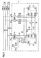
Figur 1 ein erfindungsgemäßes Steuergerät gemäß einer ersten bevorzugten Ausführungsform; und -
Figur 2 ein erfindungsgemäßes Steuergerät gemäß einer zweiten bevorzugten Ausführungsform.
-
FIG. 1 an inventive control device according to a first preferred embodiment; and -
FIG. 2 an inventive control device according to a second preferred embodiment.
In
Jedes der beiden Rechengeräte 2, 3 weist zwei separate Datenbus-Controller 4, 5 bzw. 6, 7 auf. Der erste Datenbus-Controller 4 des ersten Rechengerätes 2 umfasst einen ersten Sendeanschluss TxD1 und einen ersten Empfangsanschluss RxD1 auf. Der zweite Datenbus-Controller 5 des ersten Rechengerätes 2 umfasst einen zweiten Sendeanschluss TxD2 und einen zweiten Empfangsanschluss RxD2. Entsprechendes gilt für den ersten und zweiten Datenbus-Controller 6, 7 des zweiten Rechengerätes 3. Die Anschlüsse TxD1 der ersten Datenbus-Controller 4, 6 der beiden Rechengeräte 2, 3 sind als Gegentakt-Ausgänge, sogenannte push-pull-Anschlüsse, ausgebildet. Die beiden Anschlüsse TxD2 und RxD2 der zweiten Datenbus-Controller 5, 7 der beiden Rechengeräte 2, 3 sind als offene Kollektor-Anschlüsse, sogenannte open-collector-Anschlüsse, ausgebildet.Each of the two computing devices 2, 3 has two separate
Die beiden Rechengeräte 2, 3 kommunizieren über einen internen Datenbus 8 miteinander. Der interne Datenbus 8 umfasst eine erste Leitung 9, welche die Sendeanschlüsse TxD2 der zweiten Datenbus-Controller 5, 7 der beiden Rechengeräte 2, 3 miteinander verbindet, sowie eine zweite Leitung 10, welche die Empfangsanschlüsse RxD2 der zweiten Datenbus-Controller 5, 7 der beiden Rechengeräte 2, 3 miteinander verbindet. Aufgrund der relativ geringen Länge der Leitungen 9, 10, der geringeren Übertragungsgeschwindigkeit zwischen den beiden Rechengeräten 2, 3 über den internen Datenbus 8 und den nahezu nicht vorhandenen Störern (Potential- und/oder Pegelversetzer) kann auf den Einsatz gesonderter Sende-Empfangs-Einheiten (sogenannter Transceiver), über welche die Rechengeräte 2, 3 an die Leitungen 9, 10 angeschlossen werden können, verzichtet werden. Die Datenübertragung über den internen Datenbus 8 erfolgt nach einem bestimmten Übertragungsprotokoll, beispielsweise nach dem CAN (Controller Area Network)-Standard.The two computing devices 2, 3 communicate with each other via an
Das Steuergerät 1 umfasst außerdem zwei Sende-Empfangs-Einheiten (Transceiver) 11, 12. Die Transceiver 11, 12 stehen mit einem externen Datenbus 13 in Verbindung, der als ein CAN-Bus mit zwei Leitungen 14, 15 (CAN_H, CAN_L) ausgebildet ist. Die Transceiver 11, 12 dienen zum Aufbereiten von Signalen, die von dem externen Datenbus 13 empfangen werden oder über diesen gesendet werden sollen.The control unit 1 also comprises two transceiver units (transceivers) 11, 12. The
Gemäß einer ersten Ausgestaltung sind die beiden Rechengeräte 2, 3 derart mit dem ersten Transceiver 11 verschaltet, dass beide Rechengeräte 2, 3 über diesen einen Transceiver 11 mit dem externen Datenbus 13 in Verbindung stehen. Im Einzelnen sind die ersten Sendeanschlüsse TxD1 der ersten Datenbus-Controller 4, 6 der beiden Rechengeräte 2, 3 an die Eingänge eines UND-Gatters 16 geführt. Der Ausgang des UND-Gatters 16 ist über einen ersten Widerstand 17 an einen ersten Anschluss des Transceivers 11 geführt. Parallel zu dem UND-Gatter 16 ist von dem ersten Sendeanschluss TxD1 des ersten Datenbus-Controllers 4 des ersten Rechengerätes 2 an den Ausgang des UND-Gatters 16 ein Brückenelement 18 angeordnet.According to a first embodiment, the two computing devices 2, 3 are connected to the
Der zweite Anschluss des Transceivers 11 ist über einen zweiten Widerstand 19 an den ersten Empfangsanschluss RxD1 des ersten Datenbus-Controllers 4 des ersten Rechengerätes 2 und über ein zweites Brückenelement 20 an den ersten Empfangsanschluss RxD1 des ersten Datenbus-Controllers 6 des zweiten Rechengerätes 3 angeschlossen. An dem Ausgang des UND-Gatters 16 liegt ein dominanter Signalpegel an, wenn das erste Rechengerät 2 oder das zweite Rechengerät 3 einen dominanten Signalpegel aussendet, oder wenn beide Rechengeräte 2, 3 einen dominanten Signalpegel aussenden. Es liegt nur dann kein dominanter Signalpegel an, wenn beide Rechengeräte 2, 3 inaktiv sind. Insofern werden also die zu sendenden Signale von beiden Rechengeräten 2, 3 über den Transceiver 11 an den externen Datenbus 13 weitergeleitet. Von dem Datenbus 13 empfangene Signale werden über den Transceiver 11 an beide Rechengeräte 2, 3 geleitet.The second terminal of the
Zur Realisierung dieser Funktion muss das erste Brückenelement 18 offen und das zweite Brückenelement 20 geschlossen sein. Da jeder Datenbus-Controller 4 bis 7 nur eine begrenzte Anzahl an Nachrichten-Objekten, sogenannten Message-Objects, verwalten kann, hat die beschriebene erste Ausgestaltung des erfindungsgemäßen Steuergeräts 1 den Vorteil, dass das Steuergerät 1 die doppelte Anzahl an Nachrichtenobjekten auf dem externen Datenbus 13 verwalten kann, da die beiden Datenbus-Controller 4, 6 jeweils die übliche Anzahl an Nachrichten, gemeinsam also doppelt so viele Nachrichten, auf dem externen Datenbus 13 verwalten können.To realize this function, the
Gemäß einer zweiten Ausgestaltung ist es auch denkbar, dass das zweite Rechengerät 3 über den externen Datenbus 13 zu übertragende Informationen zunächst über den internen Datenbus 8 an das erste Rechengerät 2 übermittelt, welches die Informationen dann über den ersten Transceiver 11 an den externen Datenbus 13 weiterleitet. In diesem Fall würde das Rechengerät 2 also gewissermaßen als eine Durchreichestation arbeiten. Zur Realisierung dieser Funktion muss ein zwischen den beiden Leitungen 9, 10 des internen Datenbusses 8 angeordnetes drittes Brückenelement 21 geschlossen sein. Beide Leitungen 9, 10 des internen Datenbusses 8 sind über einen Pull-up-Widerstand 22 an eine Versorgungsspannung Vcc, die beispielsweise 1,8 Volt, 3,3 Volt oder 5,0 Volt sein kann, angeschlossen. Auf diese Weise können Signale auf den Leitungen 9, 10, die an die open-collector-Anschlüsse TxD2 und RxD2 angeschlossen sind, auf einen Pegel "high" (1,8 Volt; 3,3 Volt; 5,0 Volt oder eine andere Spannung) angehoben werden. Diesem Zweck dienen auch die beiden Pull-up-Widerstände 23 und 24, über welche die rechengeräteseitigen Anschlüsse des Transceivers 11 an die Versorgungsspannung Vcc angeschlossen sind.According to a second embodiment, it is also conceivable for the second computing device 3 to transmit information to be transmitted via the
Für bestimmte Anwendungsfälle des Steuergerätes 1 ist es zweckmäßig, wenn das zweite Rechengerät 3 gemäß einer dritten Ausgestaltung über einen eigenen Transceiver an den externen Datenbus 13 angeschlossen ist. Zu diesem Zweck sind die Anschlüsse TxD1 und RxD1 des ersten Datenbus-Controllers 6 des zweiten Rechengerätes 3 über einen dritten Widerstand 25 und einen vierten Widerstand 26, die als Brücken dienen, an die rechengeräteseitige Anschlüsse des zweiten Transceivers 12 angeschlossen. Damit bei der gegebenen Schaltung dann beide Rechengeräte 2, 3 über gesonderte Transceiver 11, 12 auf den externen Datenbus 13 zugreifen, muss das erste Brückenelement 18 geschlossen, das UND-Gatter 16 herausgenommen, und das zweite Brückenelement 20 geöffnet werden.For certain applications of the control unit 1, it is expedient if the second computing device 3 is connected according to a third embodiment via its own transceiver to the
Während der Entwicklungs- und/oder Applikationsphase des Steuergerätes 1 kann es zweckmäßig sein, den internen Datenbus 8 auf den externen Datenbus 13 zu legen. Zu diesem Zweck sind gemäß einer vierten Ausgestaltung die beiden Leitungen 9, 10 des internen Datenbusses 8 über einen fünften Widerstand 27 und einen sechsten Widerstand 28 an die rechnergeräteseitigen Anschlüsse des zweiten Transceivers 12 angeschlossen. Auf diese Weise kann die über den internen Datenbus 8 getätigte Informationsübertragung von außerhalb des Steuergerätes 1 über den externen Datenbus 13 beobachtet und analysiert werden. Zur Realisierung dieser Funktion muss das dritte Brückenelement 21 geöffnet werden.During the development and / or application phase of the control unit 1, it may be expedient to place the
Ein wesentlicher Teil des erfindungsgemäßen Steuergerätes 1 ist ein Datenbus-Interface, welches durch die beiden Transceiver 11, 12 und diejenigen Teile der Rechengeräte 2, 3 gebildet wird, die für die Kommunikation mit dem internen Datenbus 8 und dem externen Datenbus 13 zuständig sind. Außer diesen Teilen für die Kommunikation, welche zusammen mit der erforderlichen Verschaltung das Datenbus-Interface bilden, verfügen die Rechengeräte 2, 3 darüber hinaus noch über Teile zur Erfüllung ihrer bestimmungsgemäßen Steuerungs- und/oder Regelungsfunktion. Diese Teile arbeiten beispielsweise das Steuerprogramm auf den Rechengeräten 2, 3 ab.An essential part of the control device 1 according to the invention is a data bus interface, which is provided by the two
In
Ebenso kann die Informationsübertragung zwischen den beiden Rechengeräten 2, 3 über den internen Datenbus 8 über den zweiten Transceiver 12 nach außen an den zweiten externen Datenbus 29 geführt und über diesen beobachtet werden.Likewise, the information transmission between the two computing devices 2, 3 can be guided via the
Mit Hilfe des erfindungsgemäßen multifunktionalen Datenbus-Interfaces lassen sich eine Vielzahl von Aufgaben und Funktionalitäten in dem Steuergerät 1 erzielen:With the aid of the multifunctional data bus interface according to the invention, a multiplicity of tasks and functionalities can be achieved in the control unit 1:
Mit Hilfe der elektronischen Schaltung für den internen Datenbus 8 ist eine Kommunikation der beiden Rechengeräte 2, 3 (Mikro-Controller) in dem Steuergerät 1 über den internen Datenbus 8 mit Übertragungsraten von bis zu 500 kBaud möglich. Der Datenbus 8 wird auch als Inhouse-CAN-Bus oder als steuergeräteinterner CAN-Bus bezeichnet. Falls erwünscht, und keine Verbindung an Steuergeräte-Anschlussklemmen 32 des Steuergerätes 1 erstellt wird, erfolgt der Datenaustausch der beiden Rechengeräte 2, 3 völlig diskret und ist außerhalb des Steuergerätes 1 nicht zu erfassen. Der interne Datenbus 8 ist bei entsprechender Bauteilbestückung mit externen, frei käuflichen Datenbus-Diagnose-Tools voll monitorfähig. Softwareentwickler können dadurch auf effiziente Art und Weise die Verifikation ihrer Software, insbesondere des Informationsaustausches auf den internen Datenbus 8, durchführen. Der interne Datenbus 8 kann mit einem steuergeräteexternen Datenbus 13 oder 29 über die Steuergeräte-Anschlussklemmen 32 verbunden werden. Dadurch entfällt die Konstruktion weiterer Adapterleiterplatten für Applikationszwecke. Der interne Datenbus 8 wird mit einem externen Datenbus 13, 29 verbunden, beispielsweise mit dem Ziel, Monitoring und Kommunikation mit weiteren Mikroprozessoren in anderen Steuergeräten zu betreiben.With the help of the electronic circuit for the
Mit Hilfe der elektronischen Schaltung für das Datenbus-Interface kann jeder der beiden Rechengeräte 2, 3 in dem Steuergerät 1 bei geeigneter Bauteilbestückung auf einen gemeinsamen steuergeräteexternen Datenbus 13 oder jeweils auf einen separaten Datenbus 13, 29, gegebenenfalls mit unterschiedlichen Übertragungsraten, aufgeschaltet werden. Der Bauteilaufwand und der Platzbedarf auf der Leiterplatte sind dabei äußerst gering, weil die zur Aufschaltung auf den externen Datenbus 13, 29 erforderlichen Transceiver 11, 12 flexibel genutzt werden. Insbesondere erlaubt die Schaltung die folgenden Besonderheiten:
- Bei hinreichend geringer Anzahl von zu verwaltenden Nachrichtenobjekten kann nur ein Rechengerät 2 oder 3 auf
den steuergeräteexternen Datenbus 13 geschaltet werden. Informationen, die für das andere Rechengerät 3 überden externen Datenbus 13 zu empfangen oder senden sind, werden dabei überden internen Datenbus 8 ausgetauscht. Der Vorteil liegt dabei in einem sehr geringen Bauteilaufwand. - Das zweite Rechengerät 3 kann auf den Datenbus-Pfad des ersten Rechengerätes 2 aufgeschaltet werden. Dazu ist das erste Brückenelement 18 geöffnet und das zweite Brückenelement 20 geschlossen. Dies hat den Vorteil, dass die doppelte Anzahl von Nachrichtenobjekten in dem Gesamtsystem verwaltet werden kann. Es ist nur
ein Transceiver 11 notwendig, um beide Rechengeräte 2, 3 aufden externen Datenbus 13 aufzuschalten. Die Konfiguration erlaubt weiterhin das serielle Programmieren der Mikroprozessorkerne beider Rechengeräte 2, 3 überden externen Datenbus 13 mit entsprechender Software. - Das zweite Rechengerät 3 kann über den zweiten
Transceiver 12 auf einen separaten externen Datenbus 29 aufgeschaltet werden. Voraussetzung dafür ist, dass kein Monitoring fürden internen Datenbus 8 stattfinden muss und derTransceiver 12 damit für eine Ankopplung des zweiten Rechengerätes 3 anden externen Datenbus 29 zur Verfügung steht. Damit kann das Gesamtsystem über zwei Datenbusse 13, 29 kommunizieren, die auch unterschiedliche Übertragungsraten haben können. Der bidirektionale Informtionsaustausch über das Steuergerät 1 hinweg inbeide Datenbusse Datenbusse
- With a sufficiently small number of message objects to be managed, only one computing device 2 or 3 can be switched to the
data bus 13 external to the control device. Information to be received or transmitted to the other computing device 3 via theexternal data bus 13 is exchanged via theinternal data bus 8. The advantage lies in a very low component cost. - The second computing device 3 can be switched to the data bus path of the first computing device 2. For this purpose, the
first bridge element 18 is opened and thesecond bridge element 20 is closed. This has the advantage that twice the number of message objects in the overall system can be managed. Only onetransceiver 11 is necessary in order to connect both computing devices 2, 3 to theexternal data bus 13. The configuration also allows the serial programming of the microprocessor cores of both computing devices 2, 3 via theexternal data bus 13 with appropriate software. - The second computing device 3 can be connected via the
second transceiver 12 to a separateexternal data bus 29. The prerequisite for this is that no monitoring for theinternal data bus 8 must take place and thetransceiver 12 is therefore available for coupling the second computing device 3 to theexternal data bus 29. Thus, the entire system can communicate via twodata buses data buses data buses
Mit Hilfe der beschriebenen erfindungsgemäßen elektronischen Schaltung lässt sich in einem Steuergerät 1 mit zwei Rechengeräten 2, 3, die jeweils zwei Datenbus-Controller 4, 5 bzw. 6, 7 besitzen, ein Datenbus-Interface konfigurieren, das nahezu alle Arten einer Datenbus-Vernetzung beider Rechengeräte 2, 3 ermöglicht. Es lassen sich eine Vielzahl von Funktionen mit Hilfe einer relativ einfachen Schaltung realisieren:
- Kommunikation zweier Rechengeräte 2, 3 über eine steuergeräteinterne Datenbus-
Verbindung 8 mit hoher Übertragungsrate. Der Datenaustausch ist außerhalb des Steuergerätes 1 nicht zu erfassen. - Monitoring und Kontrolle des Informationsaustausches über
den internen Datenbus 8 während der Entwicklungs- und/oder Applikationsphase - Aufschalten des internen Datenbusses 8 auf einen externen Datenbus 13
oder 29. - Zwei Rechengeräte 2, 3 werden unter Nutzung von lediglich einem
Transceiver 11 auf einen gemeinsamen externen Datenbus 13 geschaltet. Dadurch kann die doppelte Anzahl von Nachrichtenobjekten in dem Gesamtsystem verwaltet werden. - Die Mikroprozessorkerne von beiden Rechengeräten 2, 3 können nacheinander über
den externen Datenbus 13 oder parallel überdie zwei Datenbusse - CAN-Gateway-Funktionalität.
- Communication of two computing devices 2, 3 via a control unit internal
data bus connection 8 with high transmission rate. The data exchange can not be detected outside of the control unit 1. - Monitoring and control of information exchange via the
internal data bus 8 during the development and / or application phase - Connecting the
internal data bus 8 to anexternal data bus - Two computing devices 2, 3 are switched to a common
external data bus 13 using only onetransceiver 11. This can manage twice the number of message objects in the overall system. - The microprocessor cores of both computing devices 2, 3 can be sequentially programmed via the
external data bus 13 or in parallel via the twodata buses - CAN gateway functionality.
Das erfindungsgemäße Steuergerät 1 wurde für zwei Rechengeräte 2, 3 und für zwei Transceiver 11, 12 beschrieben. Selbstverständlich ist es möglich, das erfindungsgemäße Steuergerät auch mit mehr als zwei Rechengeräten und mit mehr als zwei Transceivern zu realisieren.The control unit 1 according to the invention has been described for two computing devices 2, 3 and for two
Claims (12)
- Data bus interface for a controller (1), said interface comprising:- two computing elements (2, 3), particularly two microprocessors, which communicate with one another via an internal data bus (8); and- two transmission/reception units (transceivers) (11, 12) which are connected either to the same external data bus (13) or to two different external data buses (13, 29) and are connected up to the two computing elements (2, 3) such that the two computing elements (2, 3) are connected either to the same external data bus (13) or to the two different data buses (13, 29),characterized in that a reception connection (RxD1) of the second computing element (3) is connected by means of a second bridge element (20) to a connecting line between a reception connection (RxD1) of the first computing element (2) and the second connection of the one transmission/reception unit (11),
and in that if the two computing elements (2, 3) are connected to the same external data bus (13) then the second bridge element is closed, and if the two computing elements are connected to the two different data buses (13, 29) then the second bridge element is open. - Data bus interface according to Claim 1,
characterized in that the internal data bus (8) comprises two lines (9, 10) which are connected to the two computing elements (2, 3) without transmission/reception units (transceivers). - Data bus interface according to Claim 2,
characterized in that the lines (9, 10) in the internal data bus (8) are connected to the two computing elements (2, 3) by means of open-collector connections. - Data bus interface according to one of Claims 1 to 3, characterized in that the two computing elements (2, 3) are connected to the transmission/reception units (11, 12) by means of push-pull connections.
- Data bus interface according to one of Claims 1 to 4, characterized in that a respective first connection (TxD1) of the two computing elements (2, 3) is connected to a first connection of one of the two transmission/reception units (11) via an AND gate (16).
- Data bus interface according to one of Claims 1 to 5, characterized in that a respective second connection (RxD1) of the two computing elements (2, 3) is connected directly to a second connection of the one transmission/reception unit (11).
- Data bus interface according to Claim 5 or 6,
characterized in that a first bridge element (18) is arranged in parallel with the AND gate (16) between the first connection (TxD1) of the first computing element (2) and the first connection of the one transmission/reception unit (11). - Data bus interface according to one of Claims 1 to 7, characterized in that the internal data bus (8) is connected to one of the two transmission/reception units (12) by means of a switching element (21), wherein a connection between the internal data bus (8) and the one transmission/reception unit (12) can be made and broken by means of the switching element (21).
- Data bus interface according to Claim 8,
characterized in that the switching element (21) is in the form of a third bridge element which is produced between the two lines (9, 10) of the internal data bus (8). - Data bus interface according to one of Claims 1 to 9, characterized in that the internal data bus operates on the basis of the Controller Area Network (CAN) standard.
- Data bus interface according to one of Claims 1 to 10, characterized in that at least one of the external data buses (13, 29) operates on the basis of the Controller Area Network CAN standard.
- Controller (1) having a data bus interface for accessing a data bus (13, 29) for the purpose of communication with at least one other controller via the data bus (13, 29), characterized in that the controller (1) has a data bus interface according to one of the preceding claims.
Applications Claiming Priority (1)
| Application Number | Priority Date | Filing Date | Title |
|---|---|---|---|
| DE102004042380A DE102004042380A1 (en) | 2004-09-02 | 2004-09-02 | Data bus interface for a control unit and control unit with a data bus interface |
Publications (3)
| Publication Number | Publication Date |
|---|---|
| EP1632865A2 EP1632865A2 (en) | 2006-03-08 |
| EP1632865A3 EP1632865A3 (en) | 2008-02-20 |
| EP1632865B1 true EP1632865B1 (en) | 2010-05-19 |
Family
ID=35501021
Family Applications (1)
| Application Number | Title | Priority Date | Filing Date |
|---|---|---|---|
| EP05106497A Not-in-force EP1632865B1 (en) | 2004-09-02 | 2005-07-14 | Databus interface for a controller and controller with a databus interface |
Country Status (5)
| Country | Link |
|---|---|
| US (1) | US7594054B2 (en) |
| EP (1) | EP1632865B1 (en) |
| CN (1) | CN100538677C (en) |
| AT (1) | ATE468563T1 (en) |
| DE (2) | DE102004042380A1 (en) |
Cited By (1)
| Publication number | Priority date | Publication date | Assignee | Title |
|---|---|---|---|---|
| US10291281B2 (en) | 2015-07-09 | 2019-05-14 | Continental Automotive France | Transmitter-receiver device connectable to a communications network by a CAN-type or FlexRay-type bus |
Families Citing this family (15)
| Publication number | Priority date | Publication date | Assignee | Title |
|---|---|---|---|---|
| DE102005018837A1 (en) * | 2005-04-22 | 2006-10-26 | Robert Bosch Gmbh | Method and device for synchronizing two bus systems and arrangement of two bus systems |
| DE102005048585A1 (en) * | 2005-10-06 | 2007-04-12 | Robert Bosch Gmbh | Subscriber and communication controller of a communication system and method for implementing a gateway functionality in a subscriber of a communication system |
| CN100562003C (en) * | 2006-09-01 | 2009-11-18 | 杭州中导科技开发有限公司 | Bus adapter of car running recorder CAN |
| US20110022766A1 (en) * | 2007-01-17 | 2011-01-27 | Continental Teves Ag & Co. Ohg | Circuit Arrangement For A Motor Vehicle Data Bus |
| DE102009000585B4 (en) * | 2009-02-03 | 2023-04-27 | Robert Bosch Gmbh | Synchronization of two communication networks of an electronic data processing system |
| JP2012235427A (en) * | 2011-05-09 | 2012-11-29 | Denso Corp | Connection method for bus controller, and communication system |
| CN104301191A (en) * | 2013-06-05 | 2015-01-21 | 上海联影医疗科技有限公司 | Bus system |
| JP6454876B2 (en) * | 2013-09-30 | 2019-01-23 | パナソニックIpマネジメント株式会社 | Communication device and motor control device |
| JP6421920B2 (en) * | 2014-09-03 | 2018-11-14 | カシオ計算機株式会社 | Display device, display control method thereof, and control program |
| JP6895101B2 (en) * | 2015-12-22 | 2021-06-30 | カシオ計算機株式会社 | Display module, display device and its control method, control program |
| US11374786B2 (en) * | 2018-06-14 | 2022-06-28 | Hitachi Astemo, Ltd. | Gateway device |
| CN108920398B (en) * | 2018-07-05 | 2021-01-19 | 苏州浪潮智能科技有限公司 | Cap jump circuit and design method thereof |
| CN209351354U (en) | 2018-09-28 | 2019-09-06 | 深圳市道通科技股份有限公司 | CAN circuit structure and its vehicle diagnostic equipment |
| CN110221536A (en) * | 2019-05-30 | 2019-09-10 | 中车青岛四方机车车辆股份有限公司 | A kind of Car's door controlling device |
| DE102020200803A1 (en) * | 2020-01-23 | 2021-07-29 | Robert Bosch Gesellschaft mit beschränkter Haftung | Transmitting / receiving device and communication control device for a subscriber station of a serial bus system and method for communication in a serial bus system |
Family Cites Families (19)
| Publication number | Priority date | Publication date | Assignee | Title |
|---|---|---|---|---|
| US3569847A (en) * | 1969-06-23 | 1971-03-09 | Lockheed Aircraft Corp | Amplifier system for driving shaker motors |
| US4253179A (en) * | 1977-08-17 | 1981-02-24 | Nippon Electric Co., Ltd. | Time division digital switching system with code converting and inverse-converting circuits |
| US4542502A (en) * | 1983-12-30 | 1985-09-17 | At&T Bell Laboratories | Reconfigurable collision avoiding system, station and protocol for a two path multiple access digital communications system |
| NL8700736A (en) * | 1987-03-30 | 1988-10-17 | Philips Nv | ONE-CHANNEL BUS SYSTEM FOR MASTER MASTER USE, WITH BIT CELL SYNCHRONIZATION, AND MASTER STATION FITTED WITH A BIT CELL SYNCHRONIZATION ELEMENT. |
| DE3730468A1 (en) * | 1987-09-08 | 1989-03-16 | Bergmann Kabelwerke Ag | ON-BOARD NETWORK FOR MOTOR VEHICLES AND METHOD FOR OPERATING THE ON-BOARD NETWORK |
| IT1232089B (en) * | 1989-05-04 | 1992-01-23 | Sgs Thomson Microelectronics | COMMUNICATION SYSTEM BETWEEN A MAIN PROCESSING UNIT AND PERIPHERAL UNITS |
| JP2851124B2 (en) * | 1990-04-27 | 1999-01-27 | 古河電気工業株式会社 | Multiplex transmission method |
| US5187709A (en) * | 1990-05-08 | 1993-02-16 | Caterpillar Inc. | Fault tolerant serial communications network |
| EP0496506B1 (en) * | 1991-01-25 | 2000-09-20 | Hitachi, Ltd. | Fault tolerant computer system incorporating processing units which have at least three processors |
| US5214582C1 (en) * | 1991-01-30 | 2001-06-26 | Edge Diagnostic Systems | Interactive diagnostic system for an automobile vehicle and method |
| US5274636A (en) * | 1992-04-20 | 1993-12-28 | Chrysler Corporation | Automatic multiplex data link system, symbol encoder decoder therefor |
| DE19509558A1 (en) * | 1995-03-16 | 1996-09-19 | Abb Patent Gmbh | Process for fault-tolerant communication under high real-time conditions |
| US6853292B1 (en) | 1997-03-27 | 2005-02-08 | Elan Schaltelemente Gmbh & Co Kg | Security control system, method for the operation thereof |
| US5900017A (en) * | 1997-05-14 | 1999-05-04 | International Business Machines Corporation | Snooping a variable number of cache addresses in a multiple processor system by a single snoop request |
| US5995376A (en) * | 1997-05-20 | 1999-11-30 | National Instruments Corporation | Chassis which includes configurable slot 0 locations |
| EP0881572B1 (en) * | 1997-05-28 | 2001-10-10 | Agilent Technologies, Inc. (a Delaware corporation) | Permanent failure monitoring in complex systems |
| GB2345153A (en) * | 1998-12-23 | 2000-06-28 | Motorola Ltd | Fault-tolerant microcontroller arrangement, eg for a vehicle braking system |
| DE20217059U1 (en) * | 2002-11-04 | 2003-01-16 | Raytheon Marine Gmbh | Compass with electromagnetic half-shell transformer energy transmission and optoelectronic data signal transmission |
| CN2638141Y (en) * | 2003-08-29 | 2004-09-01 | 清华大学 | Portable CAN bus analysis recorder based on CF card |
-
2004
- 2004-09-02 DE DE102004042380A patent/DE102004042380A1/en not_active Ceased
-
2005
- 2005-07-14 AT AT05106497T patent/ATE468563T1/en not_active IP Right Cessation
- 2005-07-14 DE DE502005009586T patent/DE502005009586D1/en active Active
- 2005-07-14 EP EP05106497A patent/EP1632865B1/en not_active Not-in-force
- 2005-08-29 US US11/215,706 patent/US7594054B2/en active Active
- 2005-09-02 CN CNB2005100996827A patent/CN100538677C/en not_active Expired - Fee Related
Cited By (1)
| Publication number | Priority date | Publication date | Assignee | Title |
|---|---|---|---|---|
| US10291281B2 (en) | 2015-07-09 | 2019-05-14 | Continental Automotive France | Transmitter-receiver device connectable to a communications network by a CAN-type or FlexRay-type bus |
Also Published As
| Publication number | Publication date |
|---|---|
| ATE468563T1 (en) | 2010-06-15 |
| CN100538677C (en) | 2009-09-09 |
| US7594054B2 (en) | 2009-09-22 |
| EP1632865A2 (en) | 2006-03-08 |
| EP1632865A3 (en) | 2008-02-20 |
| CN1744066A (en) | 2006-03-08 |
| US20060106966A1 (en) | 2006-05-18 |
| DE102004042380A1 (en) | 2006-03-09 |
| DE502005009586D1 (en) | 2010-07-01 |
Similar Documents
| Publication | Publication Date | Title |
|---|---|---|
| EP1632865B1 (en) | Databus interface for a controller and controller with a databus interface | |
| EP1566029B1 (en) | Gateway unit for connecting sub-networks, in particular in vehicles | |
| DE10211939A1 (en) | Coupling device for coupling devices to a bus system | |
| EP3523930B1 (en) | Motor vehicle comprising an internal data network and method for operating the motor vehicle | |
| DE102011114077A1 (en) | PLC system | |
| DE10153085A1 (en) | Programming flash memory of control unit, especially motor vehicle control unit connected via controller area network (CAN) bus, using communications link which can be switched between programming and communications elements | |
| EP2093941A1 (en) | Field bus system | |
| WO2011048145A1 (en) | Automation system and method for operating an automation system | |
| EP3575899B1 (en) | Automation system, operating method for automation system and computer program product | |
| WO2009003715A2 (en) | Fast ring redundancy of a network | |
| EP3381159B1 (en) | Direct access to bus signals in a motor vehicle | |
| WO2012110541A1 (en) | Method for transmitting data via a synchronous serial databus | |
| DE112012003005T5 (en) | Network for the transmission of information and corresponding network nodes | |
| EP2730063A1 (en) | Communication interface module for an automation system | |
| DE60319175T2 (en) | Data transmission system in the vehicle with redundant connections | |
| DE102004054016A1 (en) | Control unit for controlling and / or regulating at least one vehicle function | |
| DE102004002330A1 (en) | System for data transmission in switchgear | |
| EP3632054B1 (en) | Determination of nodes of a local data bus | |
| DE102011004360A1 (en) | Communication system with an electronic circuit controllable by a computing unit, in particular for a motor vehicle | |
| DE202015004439U1 (en) | Monitoring device and network participants | |
| EP3772206A1 (en) | Network adapter for the unidirectional transmission of data | |
| DE10239846B4 (en) | Fail-silent controller | |
| DE102019200907A1 (en) | Subscriber station for a bus system and method for data transmission in a bus system | |
| DE102011005239A1 (en) | Safety system for use in industrial automation engineering for exchanging safety-critical data, has coupler, actuator sensor interface master for controller and actuator sensor interface data bus, where controller has data bus | |
| EP1629637B1 (en) | Transmission of messages in a distributed, temporally controlled real time system |
Legal Events
| Date | Code | Title | Description |
|---|---|---|---|
| PUAI | Public reference made under article 153(3) epc to a published international application that has entered the european phase |
Free format text: ORIGINAL CODE: 0009012 |
|
| AK | Designated contracting states |
Kind code of ref document: A2 Designated state(s): AT BE BG CH CY CZ DE DK EE ES FI FR GB GR HU IE IS IT LI LT LU LV MC NL PL PT RO SE SI SK TR |
|
| AX | Request for extension of the european patent |
Extension state: AL BA HR MK YU |
|
| PUAL | Search report despatched |
Free format text: ORIGINAL CODE: 0009013 |
|
| AK | Designated contracting states |
Kind code of ref document: A3 Designated state(s): AT BE BG CH CY CZ DE DK EE ES FI FR GB GR HU IE IS IT LI LT LU LV MC NL PL PT RO SE SI SK TR |
|
| AX | Request for extension of the european patent |
Extension state: AL BA HR MK YU |
|
| 17P | Request for examination filed |
Effective date: 20080820 |
|
| AKX | Designation fees paid |
Designated state(s): AT BE BG CH CY CZ DE DK EE ES FI FR GB GR HU IE IS IT LI LT LU LV MC NL PL PT RO SE SI SK TR |
|
| GRAP | Despatch of communication of intention to grant a patent |
Free format text: ORIGINAL CODE: EPIDOSNIGR1 |
|
| GRAS | Grant fee paid |
Free format text: ORIGINAL CODE: EPIDOSNIGR3 |
|
| GRAA | (expected) grant |
Free format text: ORIGINAL CODE: 0009210 |
|
| AK | Designated contracting states |
Kind code of ref document: B1 Designated state(s): AT BE BG CH CY CZ DE DK EE ES FI FR GB GR HU IE IS IT LI LT LU LV MC NL PL PT RO SE SI SK TR |
|
| REG | Reference to a national code |
Ref country code: GB Ref legal event code: FG4D Free format text: NOT ENGLISH |
|
| REG | Reference to a national code |
Ref country code: CH Ref legal event code: EP |
|
| REG | Reference to a national code |
Ref country code: IE Ref legal event code: FG4D Free format text: LANGUAGE OF EP DOCUMENT: GERMAN |
|
| REF | Corresponds to: |
Ref document number: 502005009586 Country of ref document: DE Date of ref document: 20100701 Kind code of ref document: P |
|
| REG | Reference to a national code |
Ref country code: NL Ref legal event code: VDEP Effective date: 20100519 |
|
| LTIE | Lt: invalidation of european patent or patent extension |
Effective date: 20100519 |
|
| PG25 | Lapsed in a contracting state [announced via postgrant information from national office to epo] |
Ref country code: ES Free format text: LAPSE BECAUSE OF FAILURE TO SUBMIT A TRANSLATION OF THE DESCRIPTION OR TO PAY THE FEE WITHIN THE PRESCRIBED TIME-LIMIT Effective date: 20100830 Ref country code: SE Free format text: LAPSE BECAUSE OF FAILURE TO SUBMIT A TRANSLATION OF THE DESCRIPTION OR TO PAY THE FEE WITHIN THE PRESCRIBED TIME-LIMIT Effective date: 20100519 Ref country code: LT Free format text: LAPSE BECAUSE OF FAILURE TO SUBMIT A TRANSLATION OF THE DESCRIPTION OR TO PAY THE FEE WITHIN THE PRESCRIBED TIME-LIMIT Effective date: 20100519 |
|
| PG25 | Lapsed in a contracting state [announced via postgrant information from national office to epo] |
Ref country code: SI Free format text: LAPSE BECAUSE OF FAILURE TO SUBMIT A TRANSLATION OF THE DESCRIPTION OR TO PAY THE FEE WITHIN THE PRESCRIBED TIME-LIMIT Effective date: 20100519 Ref country code: LV Free format text: LAPSE BECAUSE OF FAILURE TO SUBMIT A TRANSLATION OF THE DESCRIPTION OR TO PAY THE FEE WITHIN THE PRESCRIBED TIME-LIMIT Effective date: 20100519 Ref country code: IS Free format text: LAPSE BECAUSE OF FAILURE TO SUBMIT A TRANSLATION OF THE DESCRIPTION OR TO PAY THE FEE WITHIN THE PRESCRIBED TIME-LIMIT Effective date: 20100919 Ref country code: FI Free format text: LAPSE BECAUSE OF FAILURE TO SUBMIT A TRANSLATION OF THE DESCRIPTION OR TO PAY THE FEE WITHIN THE PRESCRIBED TIME-LIMIT Effective date: 20100519 |
|
| PG25 | Lapsed in a contracting state [announced via postgrant information from national office to epo] |
Ref country code: CY Free format text: LAPSE BECAUSE OF FAILURE TO SUBMIT A TRANSLATION OF THE DESCRIPTION OR TO PAY THE FEE WITHIN THE PRESCRIBED TIME-LIMIT Effective date: 20100519 Ref country code: PL Free format text: LAPSE BECAUSE OF FAILURE TO SUBMIT A TRANSLATION OF THE DESCRIPTION OR TO PAY THE FEE WITHIN THE PRESCRIBED TIME-LIMIT Effective date: 20100519 Ref country code: GR Free format text: LAPSE BECAUSE OF FAILURE TO SUBMIT A TRANSLATION OF THE DESCRIPTION OR TO PAY THE FEE WITHIN THE PRESCRIBED TIME-LIMIT Effective date: 20100820 |
|
| REG | Reference to a national code |
Ref country code: IE Ref legal event code: FD4D |
|
| BERE | Be: lapsed |
Owner name: ROBERT BOSCH G.M.B.H. Effective date: 20100731 |
|
| PG25 | Lapsed in a contracting state [announced via postgrant information from national office to epo] |
Ref country code: PT Free format text: LAPSE BECAUSE OF FAILURE TO SUBMIT A TRANSLATION OF THE DESCRIPTION OR TO PAY THE FEE WITHIN THE PRESCRIBED TIME-LIMIT Effective date: 20100920 Ref country code: NL Free format text: LAPSE BECAUSE OF FAILURE TO SUBMIT A TRANSLATION OF THE DESCRIPTION OR TO PAY THE FEE WITHIN THE PRESCRIBED TIME-LIMIT Effective date: 20100519 Ref country code: IE Free format text: LAPSE BECAUSE OF FAILURE TO SUBMIT A TRANSLATION OF THE DESCRIPTION OR TO PAY THE FEE WITHIN THE PRESCRIBED TIME-LIMIT Effective date: 20100519 Ref country code: DK Free format text: LAPSE BECAUSE OF FAILURE TO SUBMIT A TRANSLATION OF THE DESCRIPTION OR TO PAY THE FEE WITHIN THE PRESCRIBED TIME-LIMIT Effective date: 20100519 Ref country code: EE Free format text: LAPSE BECAUSE OF FAILURE TO SUBMIT A TRANSLATION OF THE DESCRIPTION OR TO PAY THE FEE WITHIN THE PRESCRIBED TIME-LIMIT Effective date: 20100519 |
|
| PG25 | Lapsed in a contracting state [announced via postgrant information from national office to epo] |
Ref country code: RO Free format text: LAPSE BECAUSE OF FAILURE TO SUBMIT A TRANSLATION OF THE DESCRIPTION OR TO PAY THE FEE WITHIN THE PRESCRIBED TIME-LIMIT Effective date: 20100519 Ref country code: MC Free format text: LAPSE BECAUSE OF NON-PAYMENT OF DUE FEES Effective date: 20100731 Ref country code: CZ Free format text: LAPSE BECAUSE OF FAILURE TO SUBMIT A TRANSLATION OF THE DESCRIPTION OR TO PAY THE FEE WITHIN THE PRESCRIBED TIME-LIMIT Effective date: 20100519 Ref country code: SK Free format text: LAPSE BECAUSE OF FAILURE TO SUBMIT A TRANSLATION OF THE DESCRIPTION OR TO PAY THE FEE WITHIN THE PRESCRIBED TIME-LIMIT Effective date: 20100519 |
|
| REG | Reference to a national code |
Ref country code: CH Ref legal event code: PL |
|
| PLBE | No opposition filed within time limit |
Free format text: ORIGINAL CODE: 0009261 |
|
| STAA | Information on the status of an ep patent application or granted ep patent |
Free format text: STATUS: NO OPPOSITION FILED WITHIN TIME LIMIT |
|
| PG25 | Lapsed in a contracting state [announced via postgrant information from national office to epo] |
Ref country code: IT Free format text: LAPSE BECAUSE OF FAILURE TO SUBMIT A TRANSLATION OF THE DESCRIPTION OR TO PAY THE FEE WITHIN THE PRESCRIBED TIME-LIMIT Effective date: 20100519 |
|
| 26N | No opposition filed |
Effective date: 20110222 |
|
| PG25 | Lapsed in a contracting state [announced via postgrant information from national office to epo] |
Ref country code: CH Free format text: LAPSE BECAUSE OF NON-PAYMENT OF DUE FEES Effective date: 20100731 Ref country code: LI Free format text: LAPSE BECAUSE OF NON-PAYMENT OF DUE FEES Effective date: 20100731 |
|
| REG | Reference to a national code |
Ref country code: DE Ref legal event code: R097 Ref document number: 502005009586 Country of ref document: DE Effective date: 20110221 |
|
| PG25 | Lapsed in a contracting state [announced via postgrant information from national office to epo] |
Ref country code: BE Free format text: LAPSE BECAUSE OF NON-PAYMENT OF DUE FEES Effective date: 20100731 |
|
| PG25 | Lapsed in a contracting state [announced via postgrant information from national office to epo] |
Ref country code: AT Free format text: LAPSE BECAUSE OF NON-PAYMENT OF DUE FEES Effective date: 20100714 |
|
| PG25 | Lapsed in a contracting state [announced via postgrant information from national office to epo] |
Ref country code: HU Free format text: LAPSE BECAUSE OF FAILURE TO SUBMIT A TRANSLATION OF THE DESCRIPTION OR TO PAY THE FEE WITHIN THE PRESCRIBED TIME-LIMIT Effective date: 20101120 Ref country code: LU Free format text: LAPSE BECAUSE OF NON-PAYMENT OF DUE FEES Effective date: 20100714 Ref country code: BG Free format text: LAPSE BECAUSE OF FAILURE TO SUBMIT A TRANSLATION OF THE DESCRIPTION OR TO PAY THE FEE WITHIN THE PRESCRIBED TIME-LIMIT Effective date: 20100519 |
|
| PG25 | Lapsed in a contracting state [announced via postgrant information from national office to epo] |
Ref country code: TR Free format text: LAPSE BECAUSE OF FAILURE TO SUBMIT A TRANSLATION OF THE DESCRIPTION OR TO PAY THE FEE WITHIN THE PRESCRIBED TIME-LIMIT Effective date: 20100519 |
|
| PG25 | Lapsed in a contracting state [announced via postgrant information from national office to epo] |
Ref country code: BG Free format text: LAPSE BECAUSE OF FAILURE TO SUBMIT A TRANSLATION OF THE DESCRIPTION OR TO PAY THE FEE WITHIN THE PRESCRIBED TIME-LIMIT Effective date: 20100819 |
|
| REG | Reference to a national code |
Ref country code: FR Ref legal event code: PLFP Year of fee payment: 12 |
|
| REG | Reference to a national code |
Ref country code: FR Ref legal event code: PLFP Year of fee payment: 13 |
|
| REG | Reference to a national code |
Ref country code: FR Ref legal event code: PLFP Year of fee payment: 14 |
|
| PGFP | Annual fee paid to national office [announced via postgrant information from national office to epo] |
Ref country code: DE Payment date: 20200924 Year of fee payment: 16 Ref country code: GB Payment date: 20200724 Year of fee payment: 16 Ref country code: FR Payment date: 20200727 Year of fee payment: 16 |
|
| REG | Reference to a national code |
Ref country code: DE Ref legal event code: R119 Ref document number: 502005009586 Country of ref document: DE |
|
| GBPC | Gb: european patent ceased through non-payment of renewal fee |
Effective date: 20210714 |
|
| PG25 | Lapsed in a contracting state [announced via postgrant information from national office to epo] |
Ref country code: GB Free format text: LAPSE BECAUSE OF NON-PAYMENT OF DUE FEES Effective date: 20210714 Ref country code: DE Free format text: LAPSE BECAUSE OF NON-PAYMENT OF DUE FEES Effective date: 20220201 |
|
| PG25 | Lapsed in a contracting state [announced via postgrant information from national office to epo] |
Ref country code: FR Free format text: LAPSE BECAUSE OF NON-PAYMENT OF DUE FEES Effective date: 20210731 |