EP3575899B1 - Automation system, operating method for automation system and computer program product - Google Patents
Automation system, operating method for automation system and computer program product Download PDFInfo
- Publication number
- EP3575899B1 EP3575899B1 EP18175556.2A EP18175556A EP3575899B1 EP 3575899 B1 EP3575899 B1 EP 3575899B1 EP 18175556 A EP18175556 A EP 18175556A EP 3575899 B1 EP3575899 B1 EP 3575899B1
- Authority
- EP
- European Patent Office
- Prior art keywords
- control unit
- network
- control
- ieee
- communication interface
- Prior art date
- Legal status (The legal status is an assumption and is not a legal conclusion. Google has not performed a legal analysis and makes no representation as to the accuracy of the status listed.)
- Active
Links
Images


Classifications
-
- G—PHYSICS
- G05—CONTROLLING; REGULATING
- G05B—CONTROL OR REGULATING SYSTEMS IN GENERAL; FUNCTIONAL ELEMENTS OF SUCH SYSTEMS; MONITORING OR TESTING ARRANGEMENTS FOR SUCH SYSTEMS OR ELEMENTS
- G05B19/00—Programme-control systems
- G05B19/02—Programme-control systems electric
- G05B19/04—Programme control other than numerical control, i.e. in sequence controllers or logic controllers
- G05B19/042—Programme control other than numerical control, i.e. in sequence controllers or logic controllers using digital processors
- G05B19/0423—Input/output
-
- B—PERFORMING OPERATIONS; TRANSPORTING
- B61—RAILWAYS
- B61L—GUIDING RAILWAY TRAFFIC; ENSURING THE SAFETY OF RAILWAY TRAFFIC
- B61L15/00—Indicators provided on the vehicle or vehicle train for signalling purposes ; On-board control or communication systems
- B61L15/0018—Communication with or on the vehicle or vehicle train
- B61L15/0036—Conductor-based, e.g. using CAN-Bus, train-line or optical fibres
-
- G—PHYSICS
- G05—CONTROLLING; REGULATING
- G05B—CONTROL OR REGULATING SYSTEMS IN GENERAL; FUNCTIONAL ELEMENTS OF SUCH SYSTEMS; MONITORING OR TESTING ARRANGEMENTS FOR SUCH SYSTEMS OR ELEMENTS
- G05B19/00—Programme-control systems
- G05B19/02—Programme-control systems electric
- G05B19/04—Programme control other than numerical control, i.e. in sequence controllers or logic controllers
- G05B19/05—Programmable logic controllers, e.g. simulating logic interconnections of signals according to ladder diagrams or function charts
- G05B19/052—Linking several PLC's
-
- G—PHYSICS
- G05—CONTROLLING; REGULATING
- G05B—CONTROL OR REGULATING SYSTEMS IN GENERAL; FUNCTIONAL ELEMENTS OF SUCH SYSTEMS; MONITORING OR TESTING ARRANGEMENTS FOR SUCH SYSTEMS OR ELEMENTS
- G05B19/00—Programme-control systems
- G05B19/02—Programme-control systems electric
- G05B19/04—Programme control other than numerical control, i.e. in sequence controllers or logic controllers
- G05B19/05—Programmable logic controllers, e.g. simulating logic interconnections of signals according to ladder diagrams or function charts
- G05B19/054—Input/output
-
- G—PHYSICS
- G05—CONTROLLING; REGULATING
- G05B—CONTROL OR REGULATING SYSTEMS IN GENERAL; FUNCTIONAL ELEMENTS OF SUCH SYSTEMS; MONITORING OR TESTING ARRANGEMENTS FOR SUCH SYSTEMS OR ELEMENTS
- G05B19/00—Programme-control systems
- G05B19/02—Programme-control systems electric
- G05B19/418—Total factory control, i.e. centrally controlling a plurality of machines, e.g. direct or distributed numerical control [DNC], flexible manufacturing systems [FMS], integrated manufacturing systems [IMS], computer integrated manufacturing [CIM]
- G05B19/4185—Total factory control, i.e. centrally controlling a plurality of machines, e.g. direct or distributed numerical control [DNC], flexible manufacturing systems [FMS], integrated manufacturing systems [IMS], computer integrated manufacturing [CIM] characterised by the network communication
-
- H—ELECTRICITY
- H04—ELECTRIC COMMUNICATION TECHNIQUE
- H04L—TRANSMISSION OF DIGITAL INFORMATION, e.g. TELEGRAPHIC COMMUNICATION
- H04L12/00—Data switching networks
- H04L12/28—Data switching networks characterised by path configuration, e.g. LAN [Local Area Networks] or WAN [Wide Area Networks]
- H04L12/40—Bus networks
- H04L12/40006—Architecture of a communication node
- H04L12/40013—Details regarding a bus controller
-
- H—ELECTRICITY
- H04—ELECTRIC COMMUNICATION TECHNIQUE
- H04L—TRANSMISSION OF DIGITAL INFORMATION, e.g. TELEGRAPHIC COMMUNICATION
- H04L12/00—Data switching networks
- H04L12/28—Data switching networks characterised by path configuration, e.g. LAN [Local Area Networks] or WAN [Wide Area Networks]
- H04L12/40—Bus networks
- H04L12/40169—Flexible bus arrangements
- H04L12/40176—Flexible bus arrangements involving redundancy
- H04L12/40189—Flexible bus arrangements involving redundancy by using a plurality of bus systems
-
- H—ELECTRICITY
- H04—ELECTRIC COMMUNICATION TECHNIQUE
- H04L—TRANSMISSION OF DIGITAL INFORMATION, e.g. TELEGRAPHIC COMMUNICATION
- H04L12/00—Data switching networks
- H04L12/28—Data switching networks characterised by path configuration, e.g. LAN [Local Area Networks] or WAN [Wide Area Networks]
- H04L12/46—Interconnection of networks
- H04L12/4641—Virtual LANs, VLANs, e.g. virtual private networks [VPN]
- H04L12/4645—Details on frame tagging
-
- G—PHYSICS
- G05—CONTROLLING; REGULATING
- G05B—CONTROL OR REGULATING SYSTEMS IN GENERAL; FUNCTIONAL ELEMENTS OF SUCH SYSTEMS; MONITORING OR TESTING ARRANGEMENTS FOR SUCH SYSTEMS OR ELEMENTS
- G05B2219/00—Program-control systems
- G05B2219/30—Nc systems
- G05B2219/31—From computer integrated manufacturing till monitoring
- G05B2219/31198—VPN virtual private networks
-
- H—ELECTRICITY
- H04—ELECTRIC COMMUNICATION TECHNIQUE
- H04L—TRANSMISSION OF DIGITAL INFORMATION, e.g. TELEGRAPHIC COMMUNICATION
- H04L12/00—Data switching networks
- H04L12/28—Data switching networks characterised by path configuration, e.g. LAN [Local Area Networks] or WAN [Wide Area Networks]
- H04L12/40—Bus networks
- H04L2012/40208—Bus networks characterized by the use of a particular bus standard
- H04L2012/40215—Controller Area Network CAN
-
- H—ELECTRICITY
- H04—ELECTRIC COMMUNICATION TECHNIQUE
- H04L—TRANSMISSION OF DIGITAL INFORMATION, e.g. TELEGRAPHIC COMMUNICATION
- H04L12/00—Data switching networks
- H04L12/28—Data switching networks characterised by path configuration, e.g. LAN [Local Area Networks] or WAN [Wide Area Networks]
- H04L12/40—Bus networks
- H04L2012/4026—Bus for use in automation systems
-
- H—ELECTRICITY
- H04—ELECTRIC COMMUNICATION TECHNIQUE
- H04L—TRANSMISSION OF DIGITAL INFORMATION, e.g. TELEGRAPHIC COMMUNICATION
- H04L12/00—Data switching networks
- H04L12/28—Data switching networks characterised by path configuration, e.g. LAN [Local Area Networks] or WAN [Wide Area Networks]
- H04L12/40—Bus networks
- H04L2012/40267—Bus for use in transportation systems
- H04L2012/40293—Bus for use in transportation systems the transportation system being a train
-
- Y—GENERAL TAGGING OF NEW TECHNOLOGICAL DEVELOPMENTS; GENERAL TAGGING OF CROSS-SECTIONAL TECHNOLOGIES SPANNING OVER SEVERAL SECTIONS OF THE IPC; TECHNICAL SUBJECTS COVERED BY FORMER USPC CROSS-REFERENCE ART COLLECTIONS [XRACs] AND DIGESTS
- Y02—TECHNOLOGIES OR APPLICATIONS FOR MITIGATION OR ADAPTATION AGAINST CLIMATE CHANGE
- Y02P—CLIMATE CHANGE MITIGATION TECHNOLOGIES IN THE PRODUCTION OR PROCESSING OF GOODS
- Y02P90/00—Enabling technologies with a potential contribution to greenhouse gas [GHG] emissions mitigation
- Y02P90/02—Total factory control, e.g. smart factories, flexible manufacturing systems [FMS] or integrated manufacturing systems [IMS]
Definitions
- the present invention relates to an automation system, an operating method for an automation system and a computer program product and relates in particular to an automation system, a method and a computer program product for communication between modules of an automation system connected to one another via a backplane bus, the modules being able to exchange data directly with one another without the data to send via a master.
- an automation system for example for the automatic control of functions of a rail vehicle network, in particular for its control and management (hereinafter "TCMS", Train Control & Management System) is known, which is constructed in a modular manner from several assemblies.
- TCMS Train Control & Management System
- the housing is usually equipped with an electronic circuit board (also known as a "backplane") provided with interfaces, which is designed so that the interfaces are connected to the assemblies when the assemblies are inserted into the housing.
- the modules can be connected in different ways via the interfaces. In the case of a star-shaped line routing, the connections of the interfaces for several modules of the same type lead separately to the interface of a central module.
- the respective modules cannot physically communicate directly with one another but only directly with the central module. Communication between the modules takes place via the central module as a relay.
- the interfaces share a communication medium, ie all interfaces are connected via the same or continuous conductor paths, they represent a bus ("backplane bus” or “backplane bus”)
- backplane bus or "backplane bus”
- Various communication protocols such as CAN bus according to ISO 11898, Ethernet according to IEEE 802.3, RS-232 according to ANSI / EIA / TIA-232-F / RS-422 according to ANSI / EIA / TIA-422 are used for communication via the star-shaped cable routing or the backplane bus -B-1994 / RS-485 according to ANSI / EIA / TIA-485, USB, PCI and others known.
- automation systems are known in which the backplane bus functionality is not provided via a correspondingly designed printed circuit board, but in which the assemblies are connected to one another via single-core or multi-core flexible cables.
- the assemblies are connected to one another via single-core or multi-core flexible cables.
- automation systems with star-shaped wiring or, in particular, with a backplane bus using the CAN bus communication protocol are usually used.
- the automation system is set up in such a way that a module, as a higher-level module (master), controls the communication between the modules.
- This automation system allows the communication between individual assemblies to be sealed off from other assemblies, so that assemblies with malfunction cannot intervene in communication between other assemblies without authorization.
- the automation system from the prior art has the problem that the higher-level module is involved in every communication process, which leads to a Overload of the higher-level assembly leads, and if it fails without the provision of redundancies, it leads to the failure of the automation system.
- the pamphlet DE 10 2015 105 929 A1 discloses an automation device for redundant control of a bus user by means of a first controller and a second controller with a bus interface for communication with the bus user, a first communication interface for communication with the first controller via a first communication network, a second communication interface for communication with the second controller via a second communication network; and a processor, the processor being designed to transmit bus data received from the bus interface to the first communication interface and to the second communication interface.
- the first communication interface is designed to transmit the received bus data to the first controller
- the second communication interface is designed to transmit the received bus data to the second controller.
- the first communication interface and the second communication interface are separated from one another in terms of communication technology, and the processor is designed to transmit first communication data received via the first communication interface and second communication data received via the second communication interface to the bus subscriber via the bus interface.
- the pamphlet EP 2 661 023 A1 discloses a communication device for a redundantly operable industrial communication network. It comprises a first and a second transmitting and receiving unit, which transmits data packets within an industrial communication network either bumpy or bumpless and can be selectively switched to a bumpy or bumpless transmission mode. It is also disclosed that a special Unproblematic implementation results if data packets to be transmitted bumplessly are assigned a VLAN tag with priority 6 in accordance with the IEEE 802.1Q standard DE102012220396 A1 discloses a system and a method for maintaining machine tools and machine controls, VLAN-tagging-capable data networks enabling secure data transmission between a service computer and data processing systems of a machine manufacturer.
- the present invention is therefore based on the object of providing a method that enables direct communication between the modules, between a module and an external system, or between the external systems, or relieves the master.
- An automation system which has: a backplane bus a first assembly, the first assembly having: a first control unit which is set up to control and monitor the first assembly and to assume the function of a higher-level control unit for the automation system 1, a first Communication interface that can be connected to a first segment of a train control and management system network, a second communication interface that is connected to the backplane bus, a first network switch that connects the first communication interface, the second communication interface and the control unit so that data communication according to Ethernet protocol can take place, a second assembly, wherein the second assembly has: a second control unit, which is set up to control and monitor the second assembly, a third communication interface, which is connected to a second segment of the train control management and management system network of the train control and management system network is connected, a fourth communication interface, which is connected to the backplane bus, a second Network switch that connects the third communication interface, the fourth communication interface and the second control unit with one another in such a way that data communication takes place in accordance with the Ethernet protocol, the first
- the automation system disclosed allows several modules to communicate with one another on the backplane bus without data having to be routed via a central point (master), which reduces the workload of the central point.
- the first segment of the train control and management system network consists of a single terminal of the train control and management system network or of a sub-network via which several terminal devices of the train control and management system network are connected
- the second segment of the train control and management system network consists of a single terminal of the train control and management system network or of a sub-network via which several terminals of the train control and management system network are connected.
- the first assembly also has: a fifth communication interface, which is connected to a first segment of a communication network that forms a second VLAN (V2), which is simply marked according to IEEE 802.1Q and to which the control unit as a terminal is connected, and the automation system has a third assembly, the third assembly having: a third control unit, which is set up to control and monitor the third assembly, a sixth communication interface, which is connected to a first segment of the Communication network is connected, a seventh communication interface that is connected to the backplane bus, a third network switch that connects the sixth communication interface, the seventh communication interface and the third control unit so that data communication can take place in accordance with the Ethernet protocol, with between the first control unit and of the third control unit via the backplane bus, the VLAN (V3), which is simply marked according to IEEE 802.1Q, is established, via which the first control unit can communicate with and control the third control unit, and between the first network switch and the third network switch via the backplane bus an IEEE 802.1ad
- an automation system is preferably disclosed, wherein: the first segment of the communication network consists of a single terminal of the communication network or of a sub-network via which several terminal devices of the communication network are connected, and the second segment of the communication network consists of or consists of a single terminal of the communication network a subnet via which several terminal devices of the communication network are connected.
- an automation system having a fourth module, the fourth module having: a fourth control unit which is set up to control and monitor the fourth module and to serve as a terminal for a CAN bus, a eighth communication interface, which is connected to a first segment of a CAN bus and the fourth control unit, a ninth communication interface, which is connected to the backplane bus, a fourth network switch, which connects the ninth communication interface and the fourth control unit so that data communication according to Ethernet Protocol can take place, with the VLAN (V3) simply marked according to IEEE 802.1Q being established between the first control unit and the fourth control unit via the backplane bus, via which the first control unit can communicate with and control the fourth control unit.
- V3 simply marked according to IEEE 802.1Q
- An operating method for an automation system has the following steps: Establishing a VLAN (V3), simply marked according to IEEE 802.1Q, between the first control unit and the second control unit via the backplane bus via which the Control unit can communicate with the control unit and control it, establishment of a first VLAN (T1) marked twice in accordance with IEEE 802.1ad between the first network switch and the second network switch via the backplane bus, transmission of the data traffic of the first VLAN marked once according to IEEE 802.1Q (V1) via the first double-marked VLAN (T1) between the first network switch and the second network switch via the backplane bus.
- the operating method for an automation system is also preferably disclosed, which also has the following steps: Establishing a VLAN (V3), simply marked according to IEEE 802.1Q, between the first control unit and the third control unit via the backplane bus, via which the first control unit communicates with the third control unit and can control this, establishing a second VLAN (T2) marked twice in accordance with IEEE 802.1ad between the first network switch and the third network switch via the backplane bus. Transmission of the data traffic of the second VLAN (V2) marked once according to IEEE 802.1Q via the second VLAN (T2) marked twice between the first network switch and the third network switch via the backplane bus.
- V3 V3
- T2 second VLAN
- the operating method for an automation system is also preferably disclosed, which also has the following steps: Establishing a VLAN (V3), simply marked according to IEEE 802.1Q, between the first control unit and the fourth control unit via the backplane bus, via which the first control unit communicates with the fourth control unit and can control it.
- V3 V3
- a computer program product is also disclosed which is set up to control an automation system in such a way that one of the previously described operating methods is carried out.
- FIG. 1 With reference to Fig. 1 the structure of a first exemplary embodiment of an automation system for the method according to the invention is described.
- An automation system 1 is a system for automating technical processes in an environment of controlled devices.
- the automation system is a system for the automatic control of functions of a rail vehicle network, for example the opening and closing of train doors, the control of air conditioning systems, lighting, drive and delay devices, the output of announcements, etc.
- the automation system has a housing.
- the first assembly 2, the second assembly 4, the third assembly 6 and the fourth assembly 8 are accommodated in the housing.
- the rear circuit board 60 (also known as the “backplane”) is also provided in the housing.
- the back circuit board 60 contains the backplane bus 62 (also "backplane bus”).
- the first assembly 2 has a network switch 32 (also known as a “switch”). Several network participants can be connected to one another via the network switch 2.
- the network switch 2 uses Ethernet according to the IEEE 802.3 standard as the communication protocol.
- the Network switch 32 is set up to transmit data communication as virtual local networks (“VLAN”) in accordance with IEEE 802.1Q, simply marked (“tagged VLAN”).
- the network switch 32 is set up to transmit data communication as a nested VLAN in accordance with IEEE 802.1ad, double-tagged (“double tagged VLAN”).
- the first assembly 2 has a first communication interface 42, a second communication interface 44 and a third communication interface 45, which are connected to the network switch 32 and are set up to transmit data communication in accordance with the Ethernet protocol.
- the first communication interface 42 is connected to a multimedia network 12.
- the second communication interface 44 is connected to a train control and management system network 14 (TCMS network, “Train Control and Managing System Network”).
- the third communication interface is connected to the backplane bus 62 of the backplane 60.
- the first assembly 2 has a control unit 22.
- the control unit 22 is connected to the network switch 32 and is set up to communicate with it by means of the Ethernet protocol.
- the control unit 22 controls and monitors the first assembly 2. It also takes over the control of the automation system-internal communication networks and acts here as a higher-level control unit ("master") of the automation system 1.
- the control unit is also a terminal in the train control and management system.
- the control unit 22 is set up to transmit data communication marked twice as a VLAN according to IEEE 802.1ad.
- the second assembly 4 is constructed essentially like the first assembly 2. Deviations from assembly 2 are described below. For the rest, reference is made to the description of the first assembly 2.
- the second assembly 4 has only two communication interfaces 46, 47 which are connected to a network switch 34.
- the second assembly is connected to a TCMS terminal device 18 of the train control and management system network 14, for example a train door, via the communication interface 46.
- the second module 4 is connected to the backplane bus 62 via the communication interface 47.
- a control unit 24 controls and monitors the second assembly 4.
- the third assembly 6 is constructed essentially like the second assembly 4. Deviations from assembly 4 are described below. For the rest, reference is made to the description of the second assembly 4.
- the third assembly 6 has a communication interface 48 via which the third assembly 6 is connected to a terminal 16 of the multimedia network 12, for example a screen for displaying images and image sequences / films.
- the fourth assembly 8 is constructed essentially like the second assembly 4. Deviations from assembly 4 are described below. For the rest, reference is made to the description of the second assembly 4.
- the fourth module 8 has a communication interface 40 which is set up to be connected to a CAN bus and to transmit data communication in accordance with ISO 11898.
- a control unit 28 is connected to the communication interface 40 and works as a terminal device of the CAN bus.
- the control unit 28 is also connected to a network switch 38 and via this and a communication interface 50 to the backplane bus 62.
- the control unit 28 controls and monitors the fourth assembly 8. Via the CAN bus 15, the control unit 28 can be used to communicate with other control devices or terminal devices (not shown).
- a double-marked VLAN T3 according to IEEE 802.1ad is established between the network switches 32, 34, 36 and 38. via which the communication network V3 is tunneled.
- the data packets of the Ethernet protocol between the network switches are provided with an additional marking and an identification number for a VLAN, which allows the network switches 32, 34, 36 and 38 involved in the data communication to assign the data packet to a VLAN and to ensure that only authorized terminal devices, here the control units 22, 24, 26 and 28, participate in the data communication via the VLAN V3.
- Data communication from the VLAN V3 or the tunnel T3 is not transmitted by the network switches to other terminal devices such as, for example, the multimedia terminal device 16 or the TCMS terminal device 18.
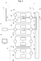
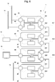
- the virtual communication network V1 in Fig. 3 Shown by solid lines, is used for communication between terminal equipment of the train control and management system network 14. Since the train control and management system network 14 is already designed as a VLAN and thus the data packets of the Ethernet protocol are marked and a VLAN identification number in accordance with IEEE 802.1Q are, it is not possible to establish a VLAN according to IEEE 802.1Q between the control unit 22, the network switch 32 and the network switch 34 to establish a VLAN. In order to expand the data traffic of the VLAN V1 over several modules, it is necessary that a double-marked VLAN according to IEEE 802.1ad is established between the control unit 22, the network switch 32 and the network switch 34.
- the VLAN marking of the train control and management system network 14 V1 is preceded by a second marking and a second VLAN identification number, an assignment of the data packet to a further, nested VLAN and thus a communication tunnel T1 is established between the control unit 22, the network switch 32 and the network switch 34.
- This allows the control unit 22, network switches 32 and 34 involved in the data communication to assign the data packet to a VLAN and to ensure that only authorized terminals, here the communication interfaces 44 and 46 and the control unit 22, participate in the data communication via the VLAN V1.
- Data communication from the VLAN V1 is not transmitted by the network switches to other terminal devices such as, for example, the multimedia terminal device 16 or the multimedia network 12.
- the Control unit 22 also represents a terminal device of the TCMS network 14 and takes on the function of a higher-level control unit.
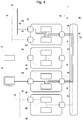
- the virtual communication network V2 in Fig. 4 Shown by solid lines, is used for communication between terminals of the multimedia network 12. Since the multimedia network 12 like the TCMS network 14 is already designed as a VLAN and thus the data packets of the Ethernet protocol with a marking and a VLAN identification number according to IEEE 802.1Q are provided, it is not possible to establish a VLAN between the network switch 32 and the network switch 36 in accordance with IEEE 802.1Q. In order to expand the data traffic of the VLAN V2 over several modules, it is necessary that a double-marked VLAN according to IEEE 802.1ad is established between the control unit 22, the network switch 32 and the network switch 36.
- the VLAN marking of the multimedia network V1 is preceded by a second marking and a second VLAN identification number, an assignment of the data packet to a further, nested VLAN is enabled and thus a communication tunnel T2 is established between the control unit 22, the network switch 32 and the network switch 36.
- This allows the control unit 22 involved in the data communication, the network switches 32 and 36, to assign the data packet to a VLAN and to ensure that only authorized terminals, here the communication interfaces 42 and 48 and the control unit 22, participate in the data communication via the VLAN V2.
- Data communication from the VLAN V1 is not transmitted by the network switches to other terminal devices such as the TCMS terminal device 18 or the TCMS network 14.
- the control unit 22 also takes on the function of a higher-level control unit when the multimedia data communication is transmitted.
- a VLAN T3 marked twice in accordance with IEEE 802.1ad is established between the first control unit 22, the first network switch 32, the second network switch 34, the third network switch 36 and the fourth network switch 38 via the backplane bus 62 established.
- a VLAN marked simply according to IEEE 802.1Q an unencrypted communication link assigned to a VLAN or another defined VLAN is used as the communication link V3 between the first control unit 22, the second control unit 24, the third control unit 26 and the fourth control unit 28 established via the VLAN T3 via the backplane bus 62, via which the first control unit 22 can communicate with and control other control units.
- a first VLAN T1 marked twice in accordance with IEEE 802.1ad is established between the first control unit 22, the first network switch 32 and the second network switch 34 via the backplane bus 62.
- a fourth step S4 data traffic of the first VLAN V1 marked singly according to IEEE 802.1Q is transmitted via the first doubly marked VLAN T1 between the first network switch (32) and the second network switch 34 via the backplane bus 62.
- a second VLAN T2 marked twice in accordance with IEEE 802.1ad is established between the first control unit 22, the first network switch 32 and the third network switch 36 via the backplane bus 62.
- a sixth step S6 data traffic of the second VLAN V2 marked once according to IEEE 802.1Q is transmitted via the second VLAN T2 marked twice between the first network switch (32) and the third network switch 34 via the backplane bus 62.
- steps S1, S2, S3, S4 and S5 take place in the specified sequence. Deviations from this are possible. There is only a sequential dependency between steps S1 with S2, as well as S3 with S4, and S5 with S6, so that the steps can otherwise be carried out in a different order or even concurrently. Such a process is in Figure 5b shown.
- FIG. 6 the structure of a second exemplary embodiment of an automation system for the method is described.
- the second exemplary embodiment is essentially the same as the first exemplary embodiment.
- the differences between the second exemplary embodiment and the first exemplary embodiment are described below. Apart from these deviations, all features and properties of the first exemplary embodiment can be transferred to the second exemplary embodiment.
- the automation system 1 ′ from the second exemplary embodiment has no housing and no rear printed circuit board. It has a first assembly 2 ', a second assembly 4', a third assembly 6 'and a fourth assembly 8'.
- the assemblies are housed in their own modules and do not share a common housing.
- the first assembly 2 ' has a fourth communication interface 451 and a fifth communication interface 452 instead of the third communication interface 45 from the first assembly 2 of the first exemplary embodiment, which are connected to the network switch 32 in such a way that Ethernet communication connections can be established via them.
- the first assembly 2 ' has all the features and functions of the first assembly 2 of the first exemplary embodiment.
- the second assembly 4 ' has a communication interface 471 and a communication interface 472 instead of the communication interface 47 from the second assembly 4 of the first exemplary embodiment, which are connected to the network switch 34 in such a way that Ethernet communication connections can be established via them.
- the second assembly 4 ' has all the features and functions of the second assembly 4 of the first exemplary embodiment.
- the communication interface 452 of the first assembly 2 ' is connected to the communication interface 471 of the second assembly 4' via a first backplane cable 621.
- the third assembly 6 ′ has a communication interface 491 and a communication interface 49 instead of the communication interface 49 from the third assembly 6 of the first exemplary embodiment Communication interface 492 which are connected to the network switch 36 in such a way that Ethernet communication connections can be established via them. Otherwise, the third assembly 6 'has all the features and functions of the third assembly 6 of the first exemplary embodiment.
- the communication interface 472 of the second assembly 4 ' is connected to the communication interface 491 of the third assembly 4' via a second backplane cable 622.
- the fourth module 8 ′ has, instead of the communication interface 50 from the fourth module 8 of the first exemplary embodiment, a communication interface 501 and a communication interface 502 which are connected to the network switch 38 in such a way that Ethernet communication connections can be established via them.
- the fourth assembly 8 ' has all the features and functions of the fourth assembly 4 of the first exemplary embodiment.
- the communication interface 472 of the third assembly 6 ' is connected to the communication interface 501 of the fourth assembly 8' via a third backplane cable 623.
- An operating method of the automation system 1 'from the second exemplary embodiment takes place in the same way as in the first exemplary embodiment, with the difference that the data communication, which takes place in the first exemplary embodiment via the backplane bus 62, in the second exemplary embodiment via the first backplane cable 621, the second backplane cable 622 or the third backplane cable 623 takes place.
- the VLAN T1 is set up from the first network switch 32 via the backplane cable 621 to the second network switch 34.
- the VLAN T2 is set up from the first network switch 32 via the backplane cable 621 to the second network switch 34 and from the second network switch 34 via the backplane cable 622 to the third network switch 36.
- the VLAN T3 is set up from the first network switch 32 via the rear wall cable 621 to the second network switch 34, from the second network switch 34 via the rear wall cable 622 to the third network switch 36 and from the third network switch 36 via the rear wall cable 623 to the fourth network switch 38.
- the assemblies 2 ', 4', 6 ', 8' are arranged in a specific order and connected to one another. This order is exemplary and any other order is possible.
- the modules 2, 2 ', 4, 4', 6, 6 ', 8, 8', the external systems 12, 14, 16, 18, and the Ethernet communication interface 42, 44, 46, 48 by means of Ethernet VLANs are divided into networks V1, V2, V3, direct communications between the modules 2, 2 ', 4, 4', 6, 6 ', 8, 8 and the external systems 12, 14, 16, 18 can be mapped specifically as required so that not all communications have to take place via a master, and thus the master is relieved.
- the networks V1 and V2 are singly marked VLANs according to IEEE 802.1Q.
- the above teaching allows the forwarding of singly marked VLANs via the backplane bus using doubly marked VLANs according to IEEE 802.1ad, but does not require VLANs according to IEEE 802.1Q, so that the V1 or V2 networks are also conventional, unencrypted and unmarked Ethernet Can handle data traffic that was previously not assigned a VLAN, or a VLAN that is not defined via markings but via connection points. The same applies to the network V3.
- the automation system is described with four modules.
- the automation system can - depending on the functional requirements - only consist of two or more modules, in particular more than four modules.
- the assemblies are described with a specific number of interfaces. However, depending on requirements, the assemblies can also have further interfaces.
- the automation system is a system for the automatic control of functions of a rail vehicle group.
- the invention is not limited to automation systems such as systems for the automatic control of functions of a rail vehicle network.
- the automation system can also be such for the control of manufacturing systems in a manufacturing plant or other.
- the automation system is provided with the backplane cables 621, 622, 623 which connect the assemblies 2 ', 4', 6 'and 8' to one another.
- the communication interfaces 451, 452, 471, 472, 491, 492, 501 and 502 can be arranged and designed on the modules in such a way that the modules are directly connected to neighboring modules via these interfaces by stacking and there is no need for a backplane bus outside the modules
- the assemblies are equipped with certain functionalities.
- the first module 2, 2 ' is connected to the multimedia network 12 and to the TCMS network 14, whereas the second module 4, 4' is connected to a terminal of the TCMS network 18 and the third module 6, 6 ' a terminal of the multimedia network 12 is connected.
- the fourth module 8, 8 ' is connected to a CAN bus.
- the functionality can also be distributed differently to the assemblies.
- one or more terminal devices from the multimedia network 12 or the train control and management network 14 or under provision can be connected to the first assembly 2, 2 ', the second assembly 4, 4' or the third assembly 6, 6 ', for example via one or more further communication interfaces a control device such as that from the fourth assembly 8, 8 ', a CAN bus can be connected.
- a control device such as that from the fourth assembly 8, 8 ', a CAN bus can be connected.
- the first control unit 22 of the first assembly 2, 2 is set up to transmit data communication as a VLAN in accordance with IEEE 802.1ad, marked twice. This is necessary in the exemplary embodiments, since the first control unit 22 transmits data communication via several, ie via the doubly marked VLANs T1, T2 and T3, and the control unit 22 differentiates between the corresponding VLANs via their marking.
- the remaining control units 24, 26, 28 transmit data communication in the exemplary embodiments only via the VLAN T3, which is why these control units do not need to differentiate between different double-marked VLANs.
- the other control units 24, 26, 28 can be set up to transmit data communication as a VLAN according to IEEE 802.1ad, marked twice. This is particularly the case when a control unit transmits data communication via more than one double-marked VLAN.
- one or more terminal devices from the multimedia network 12 or the train control and management network 14 can be connected to the first assembly 2 via one or more further communication interfaces.
- the automation system from the exemplary embodiment has a modular structure, individual assemblies, in particular the second assembly 4, the third assembly 6 or the fourth assembly 8, can be removed from the automation system, eliminating their functionality and features, and the automation system 1 can be operated in this way.
- connectives ... "and”, “or” and “either ... or” are used in the meaning that is based on the logical conjunction, the logical adjunction (often “and / or"), or the logical contravalence are.
Description
Die vorliegende Erfindung betrifft ein Automatisierungssystem, ein Betriebsverfahren für ein Automatisierungssystem und ein Computerprogrammprodukt und betrifft insbesondere ein Automatisierungssystem, ein Verfahren und ein Computerprogrammprodukt zur Kommunikation zwischen über einen Rückwandbus miteinander verbundenen Baugruppen eines Automatisierungssystems, wobei die Baugruppen direkt miteinander Daten austauschen können, ohne die Daten über einen Master zu verschicken.The present invention relates to an automation system, an operating method for an automation system and a computer program product and relates in particular to an automation system, a method and a computer program product for communication between modules of an automation system connected to one another via a backplane bus, the modules being able to exchange data directly with one another without the data to send via a master.
Im Stand der Technik ist ein Automatisierungssystem, beispielsweise zur automatischen Steuerung von Funktionen eines Schienenfahrzeugverbundes, insbesondere zu dessen Steuerung und Verwaltung (im Folgenden "TCMS", Train Control & Management System) bekannt, das aus mehreren Baugruppen modular aufgebaut ist. Hierbei werden üblicherweise mehrere Baugruppen in einem gemeinsamen Gehäuse angebracht. Sollen diese Baugruppen untereinander kommunizieren, ist üblicherweise das Gehäuse mit einer elektronischen, mit Schnittstellen versehenen Leiterplatte (auch "Backplane") ausgestattet, die so ausgeführt ist, dass die Schnittstellen mit den Baugruppen verbunden werden, wenn die Baugruppen in das Gehäuse eingesetzt werden.In the prior art, an automation system, for example for the automatic control of functions of a rail vehicle network, in particular for its control and management (hereinafter "TCMS", Train Control & Management System) is known, which is constructed in a modular manner from several assemblies. In this case, several assemblies are usually attached in a common housing. If these assemblies are to communicate with one another, the housing is usually equipped with an electronic circuit board (also known as a "backplane") provided with interfaces, which is designed so that the interfaces are connected to the assemblies when the assemblies are inserted into the housing.
Über die Schnittstellen können die Baugruppen in unterschiedlicher Form verbunden werden. Bei einer sternförmigen Leitungsführung führen die Verbindungen der Schnittstellen für mehrere gleichartige Baugruppen für sich gesondert zu der Schnittstelle einer zentralen Baugruppe. Die jeweiligen Baugruppen können dann bereits physikalisch nicht direkt untereinander sondern nur direkt mit der zentralen Baugruppe kommunizieren. Kommunikation unter den Baugruppen erfolgt über die zentrale Baugruppe als Relais.The modules can be connected in different ways via the interfaces. In the case of a star-shaped line routing, the connections of the interfaces for several modules of the same type lead separately to the interface of a central module. The respective modules cannot physically communicate directly with one another but only directly with the central module. Communication between the modules takes place via the central module as a relay.
Teilen sich die Schnittstellen ein Kommunikationsmedium, d.h. alle Schnittstellen sind über die gleichen oder durchgängige Leiterbahnen verbunden, stellen sie einen Bus ("Rückwandbus" oder auch "Backplane Bus") dar. Da es zu Übertragungsstörungen oder gar Beschädigung der angeschlossenen Baugruppen führen kann, wenn mehrere Baugruppen gleichzeitig sendend auf den Bus zuzugreifen, müssen in diesem Fall im verwendeten Kommunikationsprotokoll Mechanismen zur Buszugangsarbitrierung vorgesehen werden, um zu regeln, welcher am Bus angeschlossener Kommunikationsteilnehmer Zugang zum Kommunikationsmedium erhält, wenn mehrere Kommunikationsteilnehmer zeitgleich auf den Bus zugreifen wollen. Zur Kommunikation über die sternförmige Leitungsführung oder den Rückwandbus sind verschiedene Kommunikationsprotokolle wie CAN-Bus nach ISO 11898, Ethernet nach IEEE 802.3, RS-232 nach ANSI/EIA/TIA-232-F/RS-422 nach ANSI/EIA/TIA-422-B-1994/RS-485 nach ANSI/EIA/TIA-485, USB, PCI und weitere bekannt.If the interfaces share a communication medium, ie all interfaces are connected via the same or continuous conductor paths, they represent a bus ("backplane bus" or "backplane bus") To access several modules simultaneously sending on the bus, mechanisms for bus access arbitration must be provided in the communication protocol used in order to regulate which communication participant connected to the bus receives access to the communication medium if several communication participants want to access the bus at the same time. Various communication protocols such as CAN bus according to ISO 11898, Ethernet according to IEEE 802.3, RS-232 according to ANSI / EIA / TIA-232-F / RS-422 according to ANSI / EIA / TIA-422 are used for communication via the star-shaped cable routing or the backplane bus -B-1994 / RS-485 according to ANSI / EIA / TIA-485, USB, PCI and others known.
Alternativ sind Automatisierungssysteme bekannt, bei denen die Rückwandbusfunktionalität nicht über eine entsprechend gestaltete Leiterplatte bereitgestellt wird, sondern bei denen die Baugruppen über ein- oder mehradrige flexible Kabel miteinander verbunden werden. Insbesondere in diesen Automatisierungssystemen ist es nicht erforderlich, dass alle Baugruppen in einem gemeinsamen Gehäuse untergebracht sind, sondern an unterschiedlichen Stellen des Schienenfahrzeugs angeordnet werden können.Alternatively, automation systems are known in which the backplane bus functionality is not provided via a correspondingly designed printed circuit board, but in which the assemblies are connected to one another via single-core or multi-core flexible cables. In these automation systems in particular, it is not necessary for all the assemblies to be accommodated in a common housing, but rather to be able to be arranged at different points on the rail vehicle.
Im Stand der Technik werden üblicherweise Automatisierungssysteme mit sternförmiger Leitungsführung oder insbesondere mit Rückwandbus unter Verwendung des CAN-Buskommunikationsprotokolls eingesetzt. Hierbei ist das Automatisierungssystem so aufgebaut, dass eine Baugruppe als übergeordnete Baugruppe (Master) die Kommunikation unter den Baugruppen steuert. Dieses Automatisierungssystem erlaubt eine Abschottung der Kommunikation zwischen einzelnen Baugruppen vor anderen Baugruppen, sodass Baugruppen mit Fehlfunktion nicht unberechtigt in Kommunikation zwischen anderen Baugruppen eingreifen können.In the prior art, automation systems with star-shaped wiring or, in particular, with a backplane bus using the CAN bus communication protocol are usually used. The automation system is set up in such a way that a module, as a higher-level module (master), controls the communication between the modules. This automation system allows the communication between individual assemblies to be sealed off from other assemblies, so that assemblies with malfunction cannot intervene in communication between other assemblies without authorization.
Das Automatisierungssystem aus dem Stand der Technik weist das Problem auf, dass die übergeordnete Baugruppe an jedem Kommunikationsvorgang beteiligt ist, was zu einer Überlastung der übergeordneten Baugruppe führt, und bei deren Ausfall ohne das Vorsehen von Redundanzen zum Ausfall des Automatisierungssystems führt.The automation system from the prior art has the problem that the higher-level module is involved in every communication process, which leads to a Overload of the higher-level assembly leads, and if it fails without the provision of redundancies, it leads to the failure of the automation system.
Ferner ist es in dem bekannten Automatisierungssystem nicht möglich, Baugruppen mit weiteren Kommunikationsschnittstellen für externe Systeme vorzusehen, sodass Daten über Schnittstellen unterschiedlicher Baugruppen zwischen den externen Systemen übertragen oder weitergeleitet werden können.Furthermore, it is not possible in the known automation system to provide modules with further communication interfaces for external systems, so that data can be transmitted or forwarded between the external systems via interfaces of different modules.
Die Druckschrift
Die Druckschrift
Der vorliegenden Erfindung liegt daher die Aufgabe zugrunde ein Verfahren bereitzustellen, das eine direkte Kommunikation zwischen den Baugruppen, zwischen einer Baugruppe und einem externen System, oder zwischen den externen Systemen ermöglicht, oder den Master zu entlastet.The present invention is therefore based on the object of providing a method that enables direct communication between the modules, between a module and an external system, or between the external systems, or relieves the master.
Diese Aufgabe wird durch ein Automatisierungssystem nach Anspruch 1, ein Betriebsverfahren für ein Automatisierungssystem nach Anspruch 5 sowie ein Computerprogrammprodukt nach Anspruch 9 gelöst. Weitere vorteilhafte Entwicklungen der Erfindung sind Gegenstand der abhängigen Ansprüche.This object is achieved by an automation system according to
Offenbart ist ein Automatisierungssystem, das aufweist: einen Rückwandbus eine erste Baugruppe wobei die erste Baugruppe aufweist: eine erste Steuereinheit, die eingerichtet ist, die erste Baugruppe zu steuern und zu überwachen und für das Automatisierungssystem 1 die Funktion einer übergeordneten Steuereinheit zu übernehmen, eine erste Kommunikationsschnittstelle, die mit einem ersten Segment eines Zugsteuerungs- und Verwaltungssystem-Netz verbindbar ist, eine zweite Kommunikationsschnittstelle, die mit dem Rückwandbus verbunden ist, eine erste Netzweiche, die die erste Kommunikationsschnittstelle, die zweite Kommunikationsschnittstelle und die Steuereinheit so miteinander verbindet, dass Datenkommunikation gemäß Ethernet-Protokoll erfolgen kann, eine zweite Baugruppe wobei die zweite Baugruppe aufweist: eine zweite Steuereinheit, die eingerichtet ist, die zweite Baugruppe zu steuern und zu überwachen, eine dritte Kommunikationsschnittstelle, die mit einem zweiten Segment des Zugsteuerungs- und Verwaltungssystem-Netzes des Zugsteuerungs- und Verwaltungssystem-Netzes verbunden ist, eine vierte Kommunikationsschnittstelle, die mit dem Rückwandbus verbunden ist, eine zweite Netzweiche, die die dritte Kommunikationsschnittstelle, die vierte Kommunikationsschnittstelle und die zweite Steuereinheit so miteinander verbindet, dass Datenkommunikation gemäß Ethernet-Protokoll erfolgt, wobei die erste Netzweiche und die zweite Netzweiche eingerichtet sind, ein einfach markiertes VLAN nach IEEE 802.1Q zu etablieren und zu verarbeiten und ein zweifach markiertes VLAN nach IEEE 802.1ad zu bilden und zu verarbeiten, das Zugsteuerungs- und Verwaltungs-Netz ein nach IEEE 802.1Q erstes einfach markiertes VLAN (V1) bildet, an das die Steuereinheit als Endeinrichtung des Zugsteuerungs- und Verwaltungs-Netzes angeschlossen ist, zwischen der ersten Steuereinheit und der zweiten Steuereinheit über den Rückwandbus ein nach IEEE 802.1Q einfach markiertes VLAN (V3) etabliert ist, über das die Steuereinheit mit der Steuereinheit kommunizieren und diese steuern kann, und zwischen der ersten Netzweiche und der zweiten Netzweiche über den Rückwandbus ein nach IEEE 802.1ad erstes zweifach markiertes VLAN (T1) etabliert ist.An automation system is disclosed which has: a backplane bus a first assembly, the first assembly having: a first control unit which is set up to control and monitor the first assembly and to assume the function of a higher-level control unit for the
Das offenbarte Automatisierungssystem erlaubt mehreren Baugruppen am Rückwandbus miteinander zu kommunizieren, ohne dass Daten über eine zentrale Stelle (Master) geführt werden müssen, wodurch die Arbeitslast der zentralen Stelle sinkt.The automation system disclosed allows several modules to communicate with one another on the backplane bus without data having to be routed via a central point (master), which reduces the workload of the central point.
Offenbart ist ferner vorzugsweise ein Automatisierungssystem, wobei das erste Segment des Zugsteuerungs- und Verwaltungssystem-Netzes aus einer einzelnen Endeinrichtung des Zugsteuerungs- und Verwaltungssystem-Netzes besteht oder aus einem Teilnetz, über das mehrere Endeinrichtungen des Zugsteuerungs- und Verwaltungssystem-Netzes angeschlossen sind, und das zweite Segment des Zugsteuerungs- und Verwaltungssystem-Netzes aus einer einzelnen Endeinrichtung des Zugsteuerungs- und Verwaltungssystem-Netzes besteht oder aus einem Teilnetz, über das mehrere Endeinrichtungen des Zugsteuerungs- und Verwaltungssystem-Netzes angeschlossen sind.Also disclosed is preferably an automation system, wherein the first segment of the train control and management system network consists of a single terminal of the train control and management system network or of a sub-network via which several terminal devices of the train control and management system network are connected, and the second segment of the train control and management system network consists of a single terminal of the train control and management system network or of a sub-network via which several terminals of the train control and management system network are connected.
Offenbart ist ferner vorzugsweise, dass bei dem Automatisierungssystem die erste Baugruppe ferner aufweist: eine fünfte Kommunikationsschnittstelle, die mit einem ersten Segment eines Kommunikationsnetzes verbunden ist, das ein nach IEEE 802.1Q zweites einfach markiertes VLAN (V2) bildet, an das die Steuereinheit als Endeinrichtung angeschlossen ist, und das Automatisierungssystem eine dritte Baugruppe aufweist, wobei die dritte Baugruppe aufweist: eine dritte Steuereinheit, die eingerichtet ist, die dritte Baugruppe zu steuern und zu überwachen, eine sechste Kommunikationsschnittstelle, die mit einem ersten Segment des Kommunikationsnetzes verbunden ist, eine siebte Kommunikationsschnittstelle, die mit dem Rückwandbus verbunden ist, eine dritte Netzweiche, die die sechste Kommunikationsschnittstelle, die siebte Kommunikationsschnittstelle und die dritte Steuereinheit so miteinander verbindet, dass Datenkommunikation gemäß Ethernet-Protokoll erfolgen kann, wobei zwischen der ersten Steuereinheit und der dritten Steuereinheit über den Rückwandbus das nach IEEE 802.1Q einfach markiertes VLAN (V3) etabliert ist, über das die erste Steuereinheit mit der dritten Steuereinheit kommunizieren und diese steuern kann, und zwischen der ersten Netzweiche und der dritten Netzweiche über den Rückwandbus ein nach IEEE 802.1ad zweites zweifach markiertes VLAN (T2) etabliert ist.It is also preferably disclosed that in the automation system the first assembly also has: a fifth communication interface, which is connected to a first segment of a communication network that forms a second VLAN (V2), which is simply marked according to IEEE 802.1Q and to which the control unit as a terminal is connected, and the automation system has a third assembly, the third assembly having: a third control unit, which is set up to control and monitor the third assembly, a sixth communication interface, which is connected to a first segment of the Communication network is connected, a seventh communication interface that is connected to the backplane bus, a third network switch that connects the sixth communication interface, the seventh communication interface and the third control unit so that data communication can take place in accordance with the Ethernet protocol, with between the first control unit and of the third control unit via the backplane bus, the VLAN (V3), which is simply marked according to IEEE 802.1Q, is established, via which the first control unit can communicate with and control the third control unit, and between the first network switch and the third network switch via the backplane bus an IEEE 802.1ad second double-marked VLAN (T2) is established.
Offenbart ist ferner vorzugsweise ein Automatisierungssystem, wobei: das erste Segment des Kommunikationsnetzes aus einer einzelnen Endeinrichtung des Kommunikationsnetzes besteht oder aus einem Teilnetz, über das mehrere Endeinrichtungen des Kommunikationsnetzes angeschlossen sind, und das zweite Segment des Kommunikationsnetzes aus einer einzelnen Endeinrichtung des Kommunikationsnetzes besteht oder aus einem Teilnetz, über das mehrere Endeinrichtungen des Kommunikationsnetzes angeschlossen sind.Furthermore, an automation system is preferably disclosed, wherein: the first segment of the communication network consists of a single terminal of the communication network or of a sub-network via which several terminal devices of the communication network are connected, and the second segment of the communication network consists of or consists of a single terminal of the communication network a subnet via which several terminal devices of the communication network are connected.
Offenbart ist ferner vorzugsweise ein Automatisierungssystem, wobei das Automatisierungssystem eine vierte Baugruppe aufweist, wobei die vierte Baugruppe aufweist: eine vierte Steuereinheit, die eingerichtet ist, die vierte Baugruppe zu steuern und zu überwachen, und für einen CAN-Bus als Endgerät zu dienen, eine achte Kommunikationsschnittstelle, die mit einem ersten Segment eines CAN-Busses und der vierten Steuereinheit verbunden ist, eine neunte Kommunikationsschnittstelle, die mit dem Rückwandbus verbunden ist, eine vierte Netzweiche, die die neunte Kommunikationsschnittstelle und die vierte Steuereinheit so miteinander verbindet, dass Datenkommunikation gemäß Ethernet-Protokoll erfolgen kann, wobei zwischen der ersten Steuereinheit und der vierten Steuereinheit über den Rückwandbus das nach IEEE 802.1Q einfach markiertes VLAN (V3) etabliert ist, über das die erste Steuereinheit mit der vierten Steuereinheit kommunizieren und diese steuern kann.Also disclosed is preferably an automation system, the automation system having a fourth module, the fourth module having: a fourth control unit which is set up to control and monitor the fourth module and to serve as a terminal for a CAN bus, a eighth communication interface, which is connected to a first segment of a CAN bus and the fourth control unit, a ninth communication interface, which is connected to the backplane bus, a fourth network switch, which connects the ninth communication interface and the fourth control unit so that data communication according to Ethernet Protocol can take place, with the VLAN (V3) simply marked according to IEEE 802.1Q being established between the first control unit and the fourth control unit via the backplane bus, via which the first control unit can communicate with and control the fourth control unit.
Offenbart ist ferner ein Betriebsverfahren für ein Automatisierungssystem, dass die Schritte aufweist: Etablieren eines nach IEEE 802.1Q einfach markierten VLANs (V3) zwischen der ersten Steuereinheit und der zweiten Steuereinheit über den Rückwandbus, über das die Steuereinheit mit der Steuereinheit kommunizieren und diese steuern kann, Etablieren eines nach IEEE 802.1ad ersten zweifach markierten VLANs (T1) zwischen der ersten Netzweiche und der zweiten Netzweiche über den Rückwandbus, Übermitteln des Datenverkehrs des nach IEEE 802.1Q ersten einfach markierten VLANs (V1) über das erste zweifach markierte VLAN (T1) zwischen der ersten Netzweiche und der zweiten Netzweiche über den Rückwandbus.An operating method for an automation system is also disclosed that has the following steps: Establishing a VLAN (V3), simply marked according to IEEE 802.1Q, between the first control unit and the second control unit via the backplane bus via which the Control unit can communicate with the control unit and control it, establishment of a first VLAN (T1) marked twice in accordance with IEEE 802.1ad between the first network switch and the second network switch via the backplane bus, transmission of the data traffic of the first VLAN marked once according to IEEE 802.1Q (V1) via the first double-marked VLAN (T1) between the first network switch and the second network switch via the backplane bus.
Offenbart ist ferner vorzugsweise das Betriebsverfahren für ein Automatisierungssystem, das ferner die Schritte aufweist: Etablieren eines nach IEEE 802.1Q einfach markierten VLANs (V3) zwischen der ersten Steuereinheit und der dritten Steuereinheit über den Rückwandbus, über das die erste Steuereinheit mit der dritten Steuereinheit kommunizieren und diese steuern kann, Etablieren eines nach IEEE 802.1ad zweiten zweifach markierten VLAN (T2) zwischen der ersten Netzweiche und der dritten Netzweiche über den Rückwandbus. Übermitteln des Datenverkehrs des nach IEEE 802.1Q zweiten einfach markiertes VLAN (V2) über das zweite zweifach markiertes VLAN (T2) zwischen der ersten Netzweiche und der dritten Netzweiche über den Rückwandbus.The operating method for an automation system is also preferably disclosed, which also has the following steps: Establishing a VLAN (V3), simply marked according to IEEE 802.1Q, between the first control unit and the third control unit via the backplane bus, via which the first control unit communicates with the third control unit and can control this, establishing a second VLAN (T2) marked twice in accordance with IEEE 802.1ad between the first network switch and the third network switch via the backplane bus. Transmission of the data traffic of the second VLAN (V2) marked once according to IEEE 802.1Q via the second VLAN (T2) marked twice between the first network switch and the third network switch via the backplane bus.
Offenbart ist ferner vorzugsweise das Betriebsverfahren für ein Automatisierungssystem, das ferner die Schritte aufweist: Etablieren eines nach IEEE 802.1Q einfach markierten VLANs (V3) zwischen der ersten Steuereinheit und der vierten Steuereinheit über den Rückwandbus, über das die erste Steuereinheit mit der vierten Steuereinheit kommunizieren und diese steuern kann.The operating method for an automation system is also preferably disclosed, which also has the following steps: Establishing a VLAN (V3), simply marked according to IEEE 802.1Q, between the first control unit and the fourth control unit via the backplane bus, via which the first control unit communicates with the fourth control unit and can control it.
Offenbart ist ferner ein Computerprogrammprodukt, das eingerichtet ist, ein Automatisierungssystem so zu steuern, dass eines der vorher beschriebenen Betriebsverfahren ausgeführt wird.A computer program product is also disclosed which is set up to control an automation system in such a way that one of the previously described operating methods is carried out.
Ein Ausführungsbeispiel für das Verfahren gemäß der vorliegenden Erfindung wird anhand der nachfolgend aufgeführten Figuren erläutert. Hierbei ist das Ausführungsbeispiel als beispielhafte Implementierung des erfindungsgemäßen Verfahrens vorgesehen, die den Erfindungsgegenstand, wie er in den Ansprüchen definiert ist, nicht einschränkt.
-
Fig. 1 zeigt ein Schaubild eins ersten Ausführungsbeispiels der Erfindung. -
Fig. 2 zeigt ein Schaubild des virtuellen Netzes V3 aus dem ersten Ausführungsbeispiel. -
Fig. 3 zeigt ein Schaubild des virtuellen Netzes V1 aus dem ersten Ausführungsbeispiel. -
Fig. 4 zeigt ein Schaubild des virtuellen Netzes V2 aus dem ersten Ausführungsbeispiel. -
Fig. 5a und 5b zeigen zwei Varianten eines Ablaufdiagramms des erfindungsgemäßen Verfahrens. -
Fig. 6 zeigt ein Schaubild eines zweiten Ausführungsbeispiels der Erfindung.
-
Fig. 1 Fig. 13 shows a diagram of a first embodiment of the invention. -
Fig. 2 shows a diagram of the virtual network V3 from the first embodiment. -
Fig. 3 shows a diagram of the virtual network V1 from the first embodiment. -
Fig. 4 shows a diagram of the virtual network V2 from the first embodiment. -
Figures 5a and 5b show two variants of a flow chart of the method according to the invention. -
Fig. 6 Figure 3 shows a diagram of a second embodiment of the invention.
Unter Verweis auf
Ein Automatisierungssystem 1 ist ein System zum Automatisieren von technischen Prozessen in einer Umgebung von gesteuerten Vorrichtungen. Im vorliegenden Fall ist das Automatisierungssystem ein System zur automatischen Steuerung von Funktionen eines Schienenfahrzeugverbundes, beispielsweise dem Öffnen und Schließen von Zugtüren, der Steuerung von Klimaanlagen, Beleuchtung, Antriebs- und Verzögerungsvorrichtungen, der Ausgabe von Durchsagen, etc.An
Das Automatisierungssystem weist ein Gehäuse auf. In dem Gehäuse sind die erste Baugruppe 2, die zweite Baugruppe 4, die dritte Baugruppe 6 und die vierte Baugruppe 8 untergebracht. Ferner ist in dem Gehäuse die Rück-Leiterplatte 60 (auch "Backplane") vorgesehen.The automation system has a housing. The
Die Rück-Leiterplatte 60 beinhaltet den Rückwandbus 62 (auch "Backplane Bus").The
Die erste Baugruppe 2 weist eine Netzweiche 32 (auch "Switch") auf. Über die Netzweiche 2 können mehrere Netzteilnehmer miteinander verbunden werden. Die Netzweiche 2 verwendet als Kommunikationsprotokoll Ethernet nach dem Standard IEEE 802.3. Ferner ist die Netzweiche 32 dazu eingerichtet, Datenkommunikation als virtuelle lokale Netze ("VLAN") gemäß IEEE 802.1Q einfach markiert zu übermitteln ("tagged VLAN"). Ferner ist die Netzweiche 32 dazu eingerichtet, Datenkommunikation als geschachteltes VLAN gemäß IEEE 802.1ad doppelt markiert zu übermitteln ("double tagged VLAN").The
Die erste Baugruppe 2 weist eine erste Kommunikationsschnittstelle 42, eine zweite Kommunikationsschnittstelle 44 und eine dritte Kommunikationsschnittstelle 45 auf, die mit der Netzweiche 32 verbunden sind und eingerichtet sind, Datenkommunikation gemäß Ethernetprotokoll zu übertragen. Die erste Kommunikationsschnittstelle 42 ist mit einem Multimedianetz 12 verbunden. Die zweite Kommunikationsschnittstelle 44 ist mit einem Zugsteuerungs- und Verwaltungssystemnetz 14 (TCMS-Netz, "Train Control and Managing System Network") verbunden. Die dritte Kommunikationsschnittstelle ist mit dem Rückwandbus 62 der Rück-Leiterplatte 60 verbunden.The
Die erste Baugruppe 2 weist eine Steuereinheit 22 auf. Die Steuereinheit 22 ist mit der Netzweiche 32 verbunden und eingerichtet mittels Ethernet-Protokoll mit dieser zu kommunizieren. Die Steuereinheit 22 steuert und überwacht die erste Baugruppe 2. Ferner übernimmt sie die Steuerung der Automatisierungssystem-internen Kommunikationsnetze und fungiert hier als übergeordnete Steuereinheit ("Master") des Automatisierungssystems 1. Ferner ist die Steuereinheit eine Endeinrichtung im Zugsteuerungs- und Verwaltungssystem. Die Steuereinheit 22 ist dazu eingerichtet, Datenkommunikation als VLAN gemäß IEEE 802.1ad doppelt markiert zu übermitteln.The
Die zweite Baugruppe 4 ist im Wesentlichen wie die erste Baugruppe 2 aufgebaut. Abweichungen von Baugruppe 2 werden nachfolgend beschrieben. Im Übrigen wird auf die Beschreibung der ersten Baugruppe 2 verwiesen. Die zweite Baugruppe 4 weist lediglich zwei Kommunikationsschnittstellen 46, 47 auf, die mit einer Netzweiche 34 verbunden sind. Über die Kommunikationsschnittstelle 46 ist die zweite Baugruppe mit einer TCMS-Endeinrichtung 18 des Zugsteuerungs- und Verwaltungssystemnetzes 14 verbunden, beispielsweise einer Zugtür. Über die Kommunikationsschnittstelle 47 ist die zweite Baugruppe 4 mit dem Rückwandbus 62 verbunden. Eine Steuereinheit 24 steuert und überwacht die zweite Baugruppe 4.The
Die dritte Baugruppe 6 ist im Wesentlichen wie die zweite Baugruppe 4 aufgebaut. Abweichungen von Baugruppe 4 werden nachfolgend beschrieben. Im Übrigen wird auf die Beschreibung der zweiten Baugruppe 4 verwiesen. Die dritte Baugruppe 6 weist eine Kommunikationsschnittstelle 48 auf, über die die dritte Baugruppe 6 mit einer Endeinrichtung 16 des Multimedia-Netzes 12 verbunden, beispielsweise einem Bildschirm zur Darstellung von Bildern und Bildsequenzen/Filmen.The
Die vierte Baugruppe 8 ist im Wesentlichen wie die zweite Baugruppe 4 aufgebaut. Abweichungen von Baugruppe 4 werden nachfolgend beschrieben. Im Übrigen wird auf die Beschreibung der zweiten Baugruppe 4 verwiesen. Die vierte Baugruppe 8 weist eine Kommunikationsschnittstelle 40 auf, die eingerichtet ist, an einen CAN-Bus angeschlossen zu werden und Datenkommunikation gemäß ISO 11898 zu übertragen. Eine Steuereinheit 28 ist mit der Kommunikationsschnittstelle 40 verbunden und arbeitet als Endeinrichtung des CAN-Busses. Die Steuereinheit 28 ist ferner mit einer Netzweiche 38 und über diese und eine Kommunikationsschnittstelle 50 mit dem Rückwandbus 62 verbunden. Die Steuereinheit 28 steuert und überwacht die vierte Baugruppe 8. Über den CAN-Bus 15 kann über die Steuereinheit 28 mit weiteren, nicht dargestellten Steuergeräten oder Endeinrichtungen kommuniziert werden.The
Anhand von
Das Kommunikationsnetz V3, in
Anhand von
Das virtuelle Kommunikationsnetz V1, in
Anhand von
Das virtuelle Kommunikationsnetz V2, in
Anhand von
In dem Automatisierungssystem 1 aus dem Ausführungsbeispiel wird in einem ersten Schritt S1 ein nach IEEE 802.1ad zweifach markiertes VLAN T3 zwischen der ersten Steuereinheit 22, der ersten Netzweiche 32, der zweiten Netzweiche 34, der dritten Netzweiche 36 und der vierten Netzweiche 38 über den Rückwandbus 62 etabliert.In the
In einem zweiten Schritt S2 wird ein nach IEEE 802.1Q einfach markiertes VLAN, eine nicht verschlüsselte und einem VLAN zugeordnete Kommunikationsverbindung oder ein anderweitig definiertes VLAN als Kommunikationsverbindung V3 zwischen der ersten Steuereinheit 22, der zweiten Steuereinheit 24, der dritten Steuereinheit 26 und der vierten Steuereinheit 28 über das VLAN T3 über den Rückwandbus 62 etabliert, über das die erste Steuereinheit 22 mit übrigen Steuereinheiten kommunizieren und diese steuern kann.In a second step S2, a VLAN marked simply according to IEEE 802.1Q, an unencrypted communication link assigned to a VLAN or another defined VLAN is used as the communication link V3 between the
In einem dritten Schritt S3 wird ein nach IEEE 802.1ad erstes zweifach markiertes VLAN T1 zwischen der ersten Steuereinheit 22, der ersten Netzweiche 32 und der zweiten Netzweiche 34 über den Rückwandbus 62 etabliert.In a third step S3, a first VLAN T1 marked twice in accordance with IEEE 802.1ad is established between the
In einem vierten Schritt S4 wird Datenverkehr des nach IEEE 802.1Q ersten einfach markierten VLAN V1 über das erste zweifach markiertes VLAN T1 zwischen der ersten Netzweiche (32) und der zweiten Netzweiche 34 über den Rückwandbus 62 übermittelt.In a fourth step S4, data traffic of the first VLAN V1 marked singly according to IEEE 802.1Q is transmitted via the first doubly marked VLAN T1 between the first network switch (32) and the
In einem fünften Schritt S5 wird ein nach IEEE 802.1ad zweites zweifach markiertes VLAN T2 zwischen der ersten Steuereinheit 22, der ersten Netzweiche 32 und der dritten Netzweiche 36 über den Rückwandbus 62 etabliert.In a fifth step S5, a second VLAN T2 marked twice in accordance with IEEE 802.1ad is established between the
In einem sechsten Schritt S6 wird Datenverkehr des nach IEEE 802.1Q zweiten einfach markierten VLAN V2 über das zweite zweifach markierte VLAN T2 zwischen der ersten Netzweiche (32) und der dritten Netzweiche 34 über den Rückwandbus 62 übermittelt.In a sixth step S6, data traffic of the second VLAN V2 marked once according to IEEE 802.1Q is transmitted via the second VLAN T2 marked twice between the first network switch (32) and the
Im Ausführungsbeispiel erfolgen die Schritte S1, S2, S3, S4 und S5 in der angegebenen Abfolge. Abweichungen hiervon sind möglich. Eine sequentielle Abhängigkeit besteht jeweils nur zwischen den Schritten S1 mit S2, sowie S3 mit S4, sowie S5 mit S6, sodass die Schritte im Übrigen in anderer Reihenfolge oder gar gleichlaufend ausgeführt werden können. Ein solcher Ablauf ist in
Unter Verweis auf
Das Automatisierungssystem 1' aus dem zweiten Ausführungsbeispiel weist im Gegensatz zum ersten Ausführungsbeispiel kein Gehäuse und keine Rück-Leiterplatte auf. Es weist eine erste Baugruppe 2', eine zweite Baugruppe 4', eine dritte Baugruppe 6' und eine vierte Baugruppe 8' auf. Die Baugruppen sind in eigenen Modulen untergebracht und teilen kein gemeinsames Gehäuse.In contrast to the first exemplary embodiment, the
Die erste Baugruppe 2' weist anstelle der dritten Kommunikationsschnittstelle 45 aus der ersten Baugruppe 2 des ersten Ausführungsbeispiels eine vierte Kommunikationsschnittstelle 451 und eine fünfte Kommunikationsschnittstelle 452 auf die mit der Netzweiche 32 derart verbunden sind, dass Ethernet-Kommunikationsverbindungen darüber aufgebaut werden können. Im Übrigen weist die erste Baugruppe 2' alle Merkmale und Funktionen der ersten Baugruppe 2 des ersten Ausführungsbeispiels auf.The first assembly 2 'has a
Die zweite Baugruppe 4' weist anstelle der Kommunikationsschnittstelle 47 aus der zweiten Baugruppe 4 des ersten Ausführungsbeispiels eine Kommunikationsschnittstelle 471 und eine Kommunikationsschnittstelle 472 auf die mit der Netzweiche 34 derart verbunden sind, dass Ethernet-Kommunikationsverbindungen darüber aufgebaut werden können. Im Übrigen weist die zweite Baugruppe 4' alle Merkmale und Funktionen der zweiten Baugruppe 4 des ersten Ausführungsbeispiels auf.The second assembly 4 'has a
Über ein erstes Rückwandkabel 621 ist die Kommunikationsschnittstelle 452 der ersten Baugruppe 2' mit der Kommunikationsschnittstelle 471 der zweiten Baugruppe 4' verbunden. Die dritte Baugruppe 6' weist anstelle der Kommunikationsschnittstelle 49 aus der dritten Baugruppe 6 des ersten Ausführungsbeispiels eine Kommunikationsschnittstelle 491 und eine Kommunikationsschnittstelle 492 auf die mit der Netzweiche 36 derart verbunden sind, dass Ethernet-Kommunikationsverbindungen darüber aufgebaut werden können. Im Übrigen weist die dritte Baugruppe 6' alle Merkmale und Funktionen der dritten Baugruppe 6 des ersten Ausführungsbeispiels auf.The
Über ein zweites Rückwandkabel 622 ist die Kommunikationsschnittstelle 472 der zweiten Baugruppe 4' mit der Kommunikationsschnittstelle 491 der dritten Baugruppe 4' verbunden.The
Die vierte Baugruppe 8' weist anstelle der Kommunikationsschnittstelle 50 aus der vierten Baugruppe 8 des ersten Ausführungsbeispiels eine Kommunikationsschnittstelle 501 und eine Kommunikationsschnittstelle 502 auf die mit der Netzweiche 38 derart verbunden sind, dass Ethernet-Kommunikationsverbindungen darüber aufgebaut werden können. Im Übrigen weist die vierte Baugruppe 8' alle Merkmale und Funktionen der vierten Baugruppe 4 des ersten Ausführungsbeispiels auf.The
Über ein drittes Rückwandkabel 623 ist die Kommunikationsschnittstelle 472 der dritten Baugruppe 6' mit der Kommunikationsschnittstelle 501 der vierten Baugruppe 8' verbunden.The
Ein Betriebsverfahren des Automatisierungssystems 1' aus dem zweiten Ausführungsbeispiel erfolgt in gleicher Weise wie im ersten Ausführungsbeispiel mit dem Unterschied, dass die Datenkommunikation, die im ersten Ausführungsbeispiel über den Rückwandbus 62 erfolgt, im zweiten Ausführungsbeispiel über das erste Rückwandkabel 621, das zweite Rückwandkabel 622 oder das dritte Rückwandkabel 623 erfolgt. So wird beispielsweise das VLAN T1 von der ersten Netzweiche 32 über das Rückwandkabel 621 zur zweiten Netzweiche 34 aufgebaut. Ferner wird beispielsweise das VLAN T2 von der ersten Netzweiche 32 über das Rückwandkabel 621 zur zweiten Netzweiche 34 und von der zweiten Netzweiche 34 über das Rückwandkabel 622 zur dritten Netzweiche 36 aufgebaut. Ferner wird beispielsweise das VLAN T3 von der ersten Netzweiche 32 über das Rückwandkabel 621 zur zweiten Netzweiche 34, von der zweiten Netzweiche 34 über das Rückwandkabel 622 zur dritten Netzweiche 36 und von der dritten Netzweiche 36 über das Rückwandkabel 623 zur vierten Netzweiche 38 aufgebaut.An operating method of the automation system 1 'from the second exemplary embodiment takes place in the same way as in the first exemplary embodiment, with the difference that the data communication, which takes place in the first exemplary embodiment via the
Im zweiten Ausführungsbeispiel sind die Baugruppen 2', 4', 6', 8' in einer bestimmten Reihenfolge angeordnet und miteinander verbunden. Diese Reihenfolge ist Beispielhaft und jede andere Reihenfolge ist möglich.In the second exemplary embodiment, the assemblies 2 ', 4', 6 ', 8' are arranged in a specific order and connected to one another. This order is exemplary and any other order is possible.
Da die Baugruppen 2, 2', 4, 4', 6, 6', 8, 8', die externen Systeme 12, 14, 16, 18, und die Ethernet-Kommunikationsschnittstelle 42, 44, 46, 48 mittels Ethernet-VLANs in Netzwerke V1, V2, V3 unterteilt sind, können direkte Kommunikationen zwischen den Baugruppen 2, 2', 4, 4', 6, 6', 8, 8und den externen Systeme 12, 14, 16, 18 gezielt nach dem Bedarf abgebildet werden, damit nicht alle Kommunikationen über einen Master stattfinden müssen, und somit ist der Master entlastet.Since the
In den obigen Ausführungsbeispielen handelt es sich bei den Netzen V1 und V2 um einfach markierte VLANs nach IEEE 802.1Q. Die obige Lehre erlaubt zwar die Weiterleitung einfach markierter VLANS über den Rückwandbus mittels zweifach markierter VLANS nach IEEE 802.1ad, setzt aber keine VLANs nach IEEE 802.1Q voraus, sodass es sich bei den Netzen V1 oder V2 auch um herkömmlichen, unverschlüsselten und unmarkierten Ethernet-Datenverkehr handeln kann, der zuvor kein VLAN zugeordnet war, oder einem VLAN, das nicht über Markierungen sondern über Anschlussstellen definiert ist. Das gleiche gilt für das Netz V3.In the above exemplary embodiments, the networks V1 and V2 are singly marked VLANs according to IEEE 802.1Q. The above teaching allows the forwarding of singly marked VLANs via the backplane bus using doubly marked VLANs according to IEEE 802.1ad, but does not require VLANs according to IEEE 802.1Q, so that the V1 or V2 networks are also conventional, unencrypted and unmarked Ethernet Can handle data traffic that was previously not assigned a VLAN, or a VLAN that is not defined via markings but via connection points. The same applies to the network V3.
In den obigen Ausführungsbeispielen ist das Automatisierungssystem mit vier Baugruppen beschrieben. Das Automatisierungssystem kann - je nach Funktionsbedarf - jedoch nur aus zwei oder mehr Baugruppen, insbesondere mehr als vier Baugruppen bestehen.In the above exemplary embodiments, the automation system is described with four modules. The automation system can - depending on the functional requirements - only consist of two or more modules, in particular more than four modules.
In den obigen Ausführungsbeispielen sind die Baugruppen mit einer bestimmten Anzahl an Schnittstellen beschrieben. Je nach Bedarf können die Baugruppen jedoch auch weitere Schnittstellen aufweisen.In the above exemplary embodiments, the assemblies are described with a specific number of interfaces. However, depending on requirements, the assemblies can also have further interfaces.
In den obigen Ausführungsbeispielen ist das Automatisierungssystem ein System zur automatischen Steuerung von Funktionen eines Schienenfahrzeugverbundes. Die Erfindung ist jedoch nicht auf Automatisierungssysteme wie Systeme zur automatischen Steuerung von Funktionen eines Schienenfahrzeugverbundes beschränkt. Das Automatisierungssystem kann auch ein solches zur Steuerung von Fertigungsanlagen in einem Fertigungsbetrieb oder anderes sein.In the above exemplary embodiments, the automation system is a system for the automatic control of functions of a rail vehicle group. However, the invention is not limited to automation systems such as systems for the automatic control of functions of a rail vehicle network. The automation system can also be such for the control of manufacturing systems in a manufacturing plant or other.
Im zweiten Ausführungsbeispiel ist das Automatisierungssystem mit den Rückwandkabeln 621, 622, 623 versehen, die die Baugruppen 2', 4', 6' und 8' miteinander verbinden. Alternativ können die Kommunikationsschnittstellen 451, 452, 471, 472, 491, 492, 501 und 502 so an den Baugruppen angeordnet und ausgestaltet sein dass die Baugruppen über diese Schnittstellen durch Stapeln direkt mit benachbarten Baugruppen verbunden werden und ein außerhalb der Baugruppen ausgebildeter Rückwandbus entfälltIn the second exemplary embodiment, the automation system is provided with the
In den obigen Ausführungsbeispielen sind die Baugruppen mit bestimmten Funktionalitäten ausgestattet. So ist die erste Baugruppe 2, 2' an das Multimedia-Netz 12, und an das TCMS-Netz 14 angeschlossen, wohingegen die zweite Baugruppe 4, 4' an eine Endeinrichtung des TCMS-Netzes 18 und die dritte Baugruppe 6, 6' an eine Endeinrichtung des Multimedia-Netzes 12 angeschlossen ist. Ferner ist die vierte Baugruppe 8, 8' an einen CAN-Bus angeschlossen. Erkennbar für den Fachmann lässt sich die Funktionalität auch anders auf die Baugruppen verteilen. So können an der ersten Baugruppe 2, 2' der zweiten Baugruppe 4, 4' oder der dritten Baugruppe 6, 6' beispielsweise über eine oder mehrere weitere Kommunikationsschnittstelle eine oder mehrere Endeinrichtung aus dem Multimedianetz 12 oder dem Zugsteuerungs- und Verwaltungsnetz 14 oder unter Vorsehung einer Steuervorrichtung wie jener aus der vierten Baugruppe 8, 8' ein CAN-Bus angeschlossen sein.In the above exemplary embodiments, the assemblies are equipped with certain functionalities. The
In den obigen Ausführungsbeispielen ist lediglich die erste Steuereinheit 22 der ersten Baugruppe 2, 2' eingerichtet, Datenkommunikation als VLAN gemäß IEEE 802.1ad doppelt markiert zu übermitteln. Dies ist in den Ausführungsbeispielen erforderlich, da die erste Steuereinheit 22 Datenkommunikation über mehrere, d.h. über die doppelt markierten VLAN T1, T2 und T3 übermittelt und die Steuereinheit 22 die entsprechenden VLAN über deren Markierung zu unterscheiden. Die übrigen Steuereinheiten 24, 26, 28 übertragen Datenkommunikation in den Ausführungsbeispielen lediglich über das VLAN T3, weshalb eine Differenzierung zwischen unterschiedlichen doppelt markierten VLAN durch diese Steuereinheiten nicht erforderlich ist. Je nach Funktionsumfang, insbesondere wenn mehrere Funktionen von einer Baugruppe erfüllt werden, können die übrigen Steuereinheiten 24, 26, 28 eingerichtet sein, Datenkommunikation als VLAN gemäß IEEE 802.1ad doppelt markiert zu übermitteln. Dies ist insbesondere dann der Fall, wenn eine Steuereinheit Datenkommunikation über mehr als ein doppelt markiertes VLAN überträgt.In the above exemplary embodiments, only the
So kann an der ersten Baugruppe 2 beispielsweise über eine oder mehrere weitere Kommunikationsschnittstelle eine oder mehrere Endeinrichtung aus dem Multimedianetz 12 oder dem Zugsteuerungs- und Verwaltungsnetz 14 angeschlossen sein.For example, one or more terminal devices from the
Da das Automatisierungssystem aus dem Ausführungsbeispiel modular aufgebaut ist, können einzelne Baugruppen, insbesondere die zweite Baugruppe 4, die dritte Baugruppe 6 oder die vierte Baugruppe 8 unter Wegfall deren Funktionalität und Merkmale aus dem Automatisierungssystem entfernt, und das Automatisierungssystem 1 so betrieben werden.Since the automation system from the exemplary embodiment has a modular structure, individual assemblies, in particular the
Weitere Abwandlungen der Erfindung innerhalb des Umfangs der Patentansprüche sind möglich.Further modifications of the invention within the scope of the patent claims are possible.
Die Junktoren ... "und", "oder" und "entweder ... oder" werden in der Bedeutung verwendet, die an die logische Konjunktion, die logische Adjunktion (oft "und/oder"), bzw. die logische Kontravalenz angelehnt sind.The connectives ... "and", "or" and "either ... or" are used in the meaning that is based on the logical conjunction, the logical adjunction (often "and / or"), or the logical contravalence are.
- 1 Automatisierungssystem1 automation system
- 2, 2' erste Baugruppe2, 2 'first assembly
- 4, 4' zweite Baugruppe4, 4 'second assembly
- 6, 6' dritte Baugruppe6, 6 'third assembly
- 8, 8' vierte Baugruppe8, 8 'fourth assembly
- 12 Multimedianetz12 multimedia network
- 14 TCMS-Netz14 TCMS network
- 15 CAN-Bus-Netz15 CAN bus network
- 16 Multimediaendgerät (externes System)16 multimedia terminal (external system)
- 18 TCMS-Endgerät (externes System)18 TCMS end device (external system)
- 22, 24, 26, 28 Steuereinheit22, 24, 26, 28 control unit
- 32, 34, 36, 38 Netzweiche32, 34, 36, 38 network switch
- V1, V2, V3 Virtuelles NetzV1, V2, V3 Virtual network
- T1, T2 KommunikationstunnelT1, T2 communication tunnel
- 40 Kommunikationsschnittstelle (CAN-Bus)40 communication interface (CAN bus)
- 42, 44, 45, 46, 47, 48, 48, 50, 451, 452, 471, 472, 491, 492, 501, 502 Kommunikationsschnittstelle (Ethernet)42, 44, 45, 46, 47, 48, 48, 50, 451, 452, 471, 472, 491, 492, 501, 502 communication interface (Ethernet)
- 60 Rück-Leiterplatte60 back PCB
- 62 Rückwandbus (Ethernet)62 backplane bus (Ethernet)
- 621, 622, 623 Rückwandkabel621, 622, 623 backplane cable
Claims (10)
- Automation system (1), having:a backplane bus (62),a first assembly (2), anda second assembly (4),characterised in thatthe first assembly (2) comprises:- a first control unit (22), which is designed to control and monitor the first assembly (2) and to adopt the function of a master control unit,- a first communication interface (44), which can be connected to a first segment of a train control and management system network (14),- a second communication interface (45), which is connected to the backplane bus (62),- a first network switch (32), which connects the first communication interface (42), the second communication interface (45) and the first control unit (22) to one another in such manner that data communication can take place in accordance with the Ethernet protocol,the second assembly (4) comprises:- a second control unit (24), which is designed to control and monitor the second assembly (4),- a third communication interface (46), which can be connected to a second train control and management system network (14) segment of the train control and management system network (14),- a fourth communication interface (47), which is connected to the backplane bus (62),- a second network switch (34), which is designed to connect the third communication interface (46), the fourth communication interface (47) and the second control unit (24) to one another in such manner that data communication takes place in accordance with the Ethernet protocol,wherein- the first network switch (32) and the second network switch (34) are designed to establish and process a single tagged VLAN according to IEEE 802.1Q and to form and process a double tagged VLAN (T1) according to IEEE 802.1ad,- the train control and management network (14) forms a first single tagged VLAN (V1) in accordance with IEEE 892.1Q, to which the first control unit (22) can be connected as a terminal device of the train control and management network (14),- between the first control unit (22) and the second control unit (24) a single VLAN (V3) according to IEEE 892.1Q is established by way of the backplane bus (62), via which the first control unit (22) can communicate with and control the second control unit (24), and- a first double tagged VLAN (T1) according to IEEE 802.1ad is established between the first control unit (22), the first network switch (32) and the second network switch (34).
- The automation system (1) according to Claim 1, wherein- the first segment of the train control and management system network (14) consists of an individual terminal device (18) of the train control and management system network (14), or of a sub-network by way of which several terminal devices (18) of the train control and management system network (14) are connected, and- the second segment of the train control and management system network (14) consists of an individual terminal device (18) of the train control and management system network (14), or of a sub-network by way of which several terminal devices (18) of the train control and management system network (14) are connected.
- The automation system according to either of Claims 1 and 2, wherein the first assembly further comprises:- a fifth communication interface (42) which can be connected to a first segment of a communication interface (12), which forms a second single tagged VLAN (V2) in accordance with IEEE 892.1Q, to which the first control unit (22) can be connected as a terminal device,and the automation system (1) further comprises a third assembly (6), such that the third assembly (6) comprises:- a third control unit (26), which is designed to control and monitor the third assembly (6),- a sixth communication interface (48), which can be connected to a second segment of the communication network (12),- a seventh communication interface (49), which is connected to the backplane bus (62),- a third network switch (36), which connects the sixth communication interface (48), the seventh communication interface (49) and the third control unit (26) to one another in such manner that data communication can take place in accordance with the Ethernet protocol,wherein- between the first control unit (22) and the third control unit (26), by way of the backplane bus (62) the single tagged VLAN (V3) according to IEEE 802.1Q is established, via which the first control unit (22) can communicate with and control the third control unit (26), and- between the first network switch (32) and the third network switch (36), a second tagged VALN (T2) according to IEEE 802.1ad is established by way of the backplane bus (62).
- The automation system (1) according to Claim 3, wherein:- the first segment of the communication network (12) consists of an individual terminal device (16) of the communication network (12) or of a sub-network by way of which several terminal devices (16) of the communication network (12) are connected, and- the second segment of the communication network (12) consists of an individual terminal device (16) of the communication network (12) or of a sub-network by way of which several terminal devices (16) of the communication network (12) are connected.
- The automation system (1) according to any of Claims 1 to 4, such that the automation system (1) comprises a fourth assembly (8), wherein the fourth assembly (8) comprises:- a fourth control unit (28), which is designed to control and monitor the fourth assembly (8) and which serves as a terminal device for a CAN bus,- an eighth communication interface (40), which can be connected to a first segment of a CAN bus and to the fourth control unit (28),- a ninth communication interface (50), which is connected to the backplane bus (62),- a fourth network switch (36), which connects the ninth communication interface (50) and the fourth control unit (28) to one another in such manner that data communication according to the Ethernet protocol can take place,- wherein by way of the backplane bus (62) the single tagged VLAN (V3) according to IEEE 802.1Q between the first control unit (22) and the fourth control unit (28) is established, via which the first control unit (22) can communicate with and control the fourth control unit (28).
- The automation system (1) according to any of Claims 1 to 5, wherein the first control unit (22) or the second control unit (24) is designed to establish a second double tagged VLAN according to IEEE 802.1ad.
- Operating method for an automation system according to either of Claims 1 or 2, which method comprises the following steps:- establishing by way of the backplane bus (62) a single tagged VLAN (V3) according to IEEE 802.1Q between the first control unit (22) and the second control unit (24), via which the control unit (22) can communicate with and control the control unit (24),- establishing by way of the backplane bus (62) a first double tagged VLAN (Y1) according to IEEE 802.1ad between the first network switch (32) and the second network switch (34),- transmitting by way of the backplane bus (62) the data traffic of the first single tagged VLAN (V1) according to IEEE 802.1Q via the first double tagged VLAN (T1) between the first network switch (32) and the second network switch (34).
- The operating method according to Claim 7 for an automation system according either of Claims 3 or 4, which further comprises the steps:- establishing by way of the backplane bus (62) a single tagged VLAN (V3) according to IEEE 802.1Q between the first control unit (22) and the third control unit (26), via which the first control unit (22) can communicate with and control the third control unit (26),- establishing by way of the backplane bus (62) a second tagged VLAN (T2) according to IEEE 892.1ad between the first network switch (32) and the third network switch (36),- transmitting by way of the backplane bus (62) the data traffic of the second single tagged VLAN (V2) according to IEEE 802.1Q via the second double tagged VLAN (T2) between the first network switch (32) and the third network switch (36).
- The operating method according to either of Claims 7 or 8 for an automation system according to Claim 5, which method further comprises the step:- establishing by way of the backplane bus (62) a single tagged VLAN (V3) according to IEEE 802.1Q between the first control unit (22) and the fourth control unit (28), via which the first control unit (22) can communicate with and control the fourth control unit (28).
- A computer program product, which is designed to control an automation system (1) according to any of Claims 1 to 6 in such manner that one of the operating methods according to any of Claims 7 to 9 is carried out.
Priority Applications (5)
| Application Number | Priority Date | Filing Date | Title |
|---|---|---|---|
| EP18175556.2A EP3575899B1 (en) | 2018-06-01 | 2018-06-01 | Automation system, operating method for automation system and computer program product |
| US15/734,097 US20210213982A1 (en) | 2018-06-01 | 2019-05-23 | Automation system, operating method for automation system, and computer program product |
| CN201980035112.1A CN112313586A (en) | 2018-06-01 | 2019-05-23 | Automation system, operating method for an automation system, and computer program product |
| PCT/EP2019/063379 WO2019228911A1 (en) | 2018-06-01 | 2019-05-23 | Automation system, operating method for automation system, and computer program product |
| HRP20210897TT HRP20210897T1 (en) | 2018-06-01 | 2021-06-07 | Automation system, operating method for automation system and computer program product |
Applications Claiming Priority (1)
| Application Number | Priority Date | Filing Date | Title |
|---|---|---|---|
| EP18175556.2A EP3575899B1 (en) | 2018-06-01 | 2018-06-01 | Automation system, operating method for automation system and computer program product |
Publications (2)
| Publication Number | Publication Date |
|---|---|
| EP3575899A1 EP3575899A1 (en) | 2019-12-04 |
| EP3575899B1 true EP3575899B1 (en) | 2021-03-17 |
Family
ID=62684578
Family Applications (1)
| Application Number | Title | Priority Date | Filing Date |
|---|---|---|---|
| EP18175556.2A Active EP3575899B1 (en) | 2018-06-01 | 2018-06-01 | Automation system, operating method for automation system and computer program product |
Country Status (5)
| Country | Link |
|---|---|
| US (1) | US20210213982A1 (en) |
| EP (1) | EP3575899B1 (en) |
| CN (1) | CN112313586A (en) |
| HR (1) | HRP20210897T1 (en) |
| WO (1) | WO2019228911A1 (en) |
Families Citing this family (3)
| Publication number | Priority date | Publication date | Assignee | Title |
|---|---|---|---|---|
| DE102020121644A1 (en) | 2020-08-18 | 2022-02-24 | Weidmüller Interface GmbH & Co. KG | Modular input and output station for an industrial automation system and/or industrial IoT system |
| CN112918518B (en) * | 2021-03-19 | 2022-11-22 | 中车青岛四方车辆研究所有限公司 | Vehicle-mounted lumped electronic control platform |
| CN113291351B (en) * | 2021-06-17 | 2023-01-24 | 中车唐山机车车辆有限公司 | Train formation, train data transmission method and device, and storage medium |
Citations (1)
| Publication number | Priority date | Publication date | Assignee | Title |
|---|---|---|---|---|
| DE102012220396A1 (en) * | 2012-11-08 | 2014-05-08 | Trumpf Werkzeugmaschinen Gmbh + Co. Kg | System and method for servicing a machine tool |
Family Cites Families (13)
| Publication number | Priority date | Publication date | Assignee | Title |
|---|---|---|---|---|
| US7865251B2 (en) * | 2003-01-28 | 2011-01-04 | Fisher-Rosemount Systems, Inc. | Method for intercontroller communications in a safety instrumented system or a process control system |
| CN101320313A (en) * | 2008-06-26 | 2008-12-10 | 华为技术有限公司 | Memory apparatus |
| DE102011082965A1 (en) * | 2011-09-19 | 2013-01-24 | Siemens Aktiengesellschaft | Method for operating a network arrangement and network arrangement |
| ES2532579T3 (en) * | 2012-04-30 | 2015-03-30 | Siemens Aktiengesellschaft | Communication device for an industrial communication network that can be operated redundantly and procedure for operating a communication network |
| CN103580970A (en) * | 2012-07-26 | 2014-02-12 | 中国北车股份有限公司大连电力牵引研发中心 | Communication board card based on VME bus and data communication method |
| US9282384B1 (en) * | 2014-10-07 | 2016-03-08 | Huawei Technologies Co., Ltd. | System and method for commutation in photonic switching |
| CN104461968B (en) * | 2014-11-21 | 2017-08-11 | 华为技术有限公司 | A kind of I/O channel distribution method and device |
| DE102014226994A1 (en) * | 2014-12-29 | 2016-06-30 | Robert Bosch Gmbh | Communication system for operating a data network |
| DE102015105929A1 (en) * | 2015-04-17 | 2016-10-20 | Phoenix Contact Gmbh & Co. Kg | Automation device for redundantly controlling a bus subscriber |
| CN106789747B (en) * | 2015-11-19 | 2023-05-26 | 中车大连电力牵引研发中心有限公司 | Switch with multi-gateway function and communication system |
| CN205647560U (en) * | 2016-05-16 | 2016-10-12 | 中车青岛四方车辆研究所有限公司 | City rail vehicle braking system ethernet communication board |
| CN108008657B (en) * | 2016-10-28 | 2020-07-21 | 北京计算机技术及应用研究所 | Load balancing redundancy switching system with control panel and switching panel buses directly connected |
| CN107911288B (en) * | 2017-11-22 | 2021-07-06 | 中车大连电力牵引研发中心有限公司 | Train communication network card and train control management system |
-
2018
- 2018-06-01 EP EP18175556.2A patent/EP3575899B1/en active Active
-
2019
- 2019-05-23 CN CN201980035112.1A patent/CN112313586A/en active Pending
- 2019-05-23 WO PCT/EP2019/063379 patent/WO2019228911A1/en active Application Filing
- 2019-05-23 US US15/734,097 patent/US20210213982A1/en active Pending
-
2021
- 2021-06-07 HR HRP20210897TT patent/HRP20210897T1/en unknown
Patent Citations (1)
| Publication number | Priority date | Publication date | Assignee | Title |
|---|---|---|---|---|
| DE102012220396A1 (en) * | 2012-11-08 | 2014-05-08 | Trumpf Werkzeugmaschinen Gmbh + Co. Kg | System and method for servicing a machine tool |
Also Published As
| Publication number | Publication date |
|---|---|
| EP3575899A1 (en) | 2019-12-04 |
| US20210213982A1 (en) | 2021-07-15 |
| CN112313586A (en) | 2021-02-02 |
| HRP20210897T1 (en) | 2021-08-20 |
| WO2019228911A1 (en) | 2019-12-05 |
Similar Documents
| Publication | Publication Date | Title |
|---|---|---|
| DE4404962C2 (en) | Method and arrangement for configuring functional units in a master-slave arrangement | |
| EP2720098B1 (en) | Safety system for a plant comprising a test signal path with return path | |
| DE19756564A1 (en) | Communication network with automatic nodal configuration | |
| EP3575899B1 (en) | Automation system, operating method for automation system and computer program product | |
| DE102009049378B4 (en) | Bus-compatible connection unit for an electrical installation | |
| EP2587738B1 (en) | Method and a bus device for transferring security-oriented data | |
| WO1999014643A1 (en) | Device and method for controlling machines especially a power loom | |
| WO2018215289A1 (en) | Module unit for connecting a data bus participant | |
| DE102017125086A1 (en) | Data transmission method and communication network | |
| EP3436383B1 (en) | Lift system with central control unit and a plurality of field devices communicating over a sum frame method | |
| DE102015105929A1 (en) | Automation device for redundantly controlling a bus subscriber | |
| DE102007009552A1 (en) | Device for building automation, has functional modules that posses bus interface aligned over serial data bus for data transmission, where functional modules have supply interface separated from bus interface | |
| DE102019127195A1 (en) | Modular interface system for connecting a control device and field devices | |
| EP3401742B1 (en) | Automation system and method for operating same | |
| EP3753205B1 (en) | Data transmission in time-sensitive data networks | |
| EP3439245A1 (en) | Data transmission method between a rotary input type encoder and a motor control device or an evaluation unit | |
| WO2022038147A1 (en) | Modular input and output station for an industrial automation system and/or industrial iot system | |
| DE102011115431B4 (en) | Fieldbus network adapters and fieldbus network participants with fieldbus connections | |
| EP1334589B1 (en) | Data transmission | |
| EP1363197B1 (en) | System for transferring data between microcomputer devices | |
| DE102019200907A1 (en) | Subscriber station for a bus system and method for data transmission in a bus system | |
| EP3632054B1 (en) | Determination of nodes of a local data bus | |
| DE10323980A1 (en) | motor control | |
| EP3435179A1 (en) | Method for functionally secure exchange of information according to a safety standard | |
| EP1629637B1 (en) | Transmission of messages in a distributed, temporally controlled real time system |
Legal Events
| Date | Code | Title | Description |
|---|---|---|---|
| PUAI | Public reference made under article 153(3) epc to a published international application that has entered the european phase |
Free format text: ORIGINAL CODE: 0009012 |
|
| STAA | Information on the status of an ep patent application or granted ep patent |
Free format text: STATUS: REQUEST FOR EXAMINATION WAS MADE |
|
| 17P | Request for examination filed |
Effective date: 20180601 |
|
| AK | Designated contracting states |
Kind code of ref document: A1 Designated state(s): AL AT BE BG CH CY CZ DE DK EE ES FI FR GB GR HR HU IE IS IT LI LT LU LV MC MK MT NL NO PL PT RO RS SE SI SK SM TR |
|
| AX | Request for extension of the european patent |
Extension state: BA ME |
|
| RBV | Designated contracting states (corrected) |
Designated state(s): AL AT BE BG CH CY CZ DE DK EE ES FI FR GB GR HR HU IE IS IT LI LT LU LV MC MK MT NL NO PL PT RO RS SE SI SK SM TR |
|
| GRAP | Despatch of communication of intention to grant a patent |
Free format text: ORIGINAL CODE: EPIDOSNIGR1 |
|
| STAA | Information on the status of an ep patent application or granted ep patent |
Free format text: STATUS: GRANT OF PATENT IS INTENDED |
|
| INTG | Intention to grant announced |
Effective date: 20201019 |
|
| GRAS | Grant fee paid |
Free format text: ORIGINAL CODE: EPIDOSNIGR3 |
|
| GRAA | (expected) grant |
Free format text: ORIGINAL CODE: 0009210 |
|
| STAA | Information on the status of an ep patent application or granted ep patent |
Free format text: STATUS: THE PATENT HAS BEEN GRANTED |
|
| AK | Designated contracting states |
Kind code of ref document: B1 Designated state(s): AL AT BE BG CH CY CZ DE DK EE ES FI FR GB GR HR HU IE IS IT LI LT LU LV MC MK MT NL NO PL PT RO RS SE SI SK SM TR |
|
| REG | Reference to a national code |
Ref country code: GB Ref legal event code: FG4D Free format text: NOT ENGLISH |
|
| REG | Reference to a national code |
Ref country code: CH Ref legal event code: EP |
|
| REG | Reference to a national code |
Ref country code: DE Ref legal event code: R096 Ref document number: 502018004315 Country of ref document: DE |
|
| REG | Reference to a national code |
Ref country code: IE Ref legal event code: FG4D Free format text: LANGUAGE OF EP DOCUMENT: GERMAN |
|
| REG | Reference to a national code |
Ref country code: AT Ref legal event code: REF Ref document number: 1372815 Country of ref document: AT Kind code of ref document: T Effective date: 20210415 |
|
| REG | Reference to a national code |
Ref country code: HR Ref legal event code: TUEP Ref document number: P20210897 Country of ref document: HR |
|
| REG | Reference to a national code |
Ref country code: FI Ref legal event code: FGE |
|
| REG | Reference to a national code |
Ref country code: LT Ref legal event code: MG9D |
|
| PG25 | Lapsed in a contracting state [announced via postgrant information from national office to epo] |
Ref country code: NO Free format text: LAPSE BECAUSE OF FAILURE TO SUBMIT A TRANSLATION OF THE DESCRIPTION OR TO PAY THE FEE WITHIN THE PRESCRIBED TIME-LIMIT Effective date: 20210617 Ref country code: GR Free format text: LAPSE BECAUSE OF FAILURE TO SUBMIT A TRANSLATION OF THE DESCRIPTION OR TO PAY THE FEE WITHIN THE PRESCRIBED TIME-LIMIT Effective date: 20210618 Ref country code: BG Free format text: LAPSE BECAUSE OF FAILURE TO SUBMIT A TRANSLATION OF THE DESCRIPTION OR TO PAY THE FEE WITHIN THE PRESCRIBED TIME-LIMIT Effective date: 20210617 |
|
| REG | Reference to a national code |
Ref country code: HR Ref legal event code: ODRP Ref document number: P20210897 Country of ref document: HR Payment date: 20210629 Year of fee payment: 4 |
|
| REG | Reference to a national code |
Ref country code: HR Ref legal event code: T1PR Ref document number: P20210897 Country of ref document: HR |
|
| REG | Reference to a national code |
Ref country code: NL Ref legal event code: MP Effective date: 20210317 |
|
| PG25 | Lapsed in a contracting state [announced via postgrant information from national office to epo] |
Ref country code: RS Free format text: LAPSE BECAUSE OF FAILURE TO SUBMIT A TRANSLATION OF THE DESCRIPTION OR TO PAY THE FEE WITHIN THE PRESCRIBED TIME-LIMIT Effective date: 20210317 Ref country code: LV Free format text: LAPSE BECAUSE OF FAILURE TO SUBMIT A TRANSLATION OF THE DESCRIPTION OR TO PAY THE FEE WITHIN THE PRESCRIBED TIME-LIMIT Effective date: 20210317 Ref country code: SE Free format text: LAPSE BECAUSE OF FAILURE TO SUBMIT A TRANSLATION OF THE DESCRIPTION OR TO PAY THE FEE WITHIN THE PRESCRIBED TIME-LIMIT Effective date: 20210317 |
|
| PG25 | Lapsed in a contracting state [announced via postgrant information from national office to epo] |
Ref country code: NL Free format text: LAPSE BECAUSE OF FAILURE TO SUBMIT A TRANSLATION OF THE DESCRIPTION OR TO PAY THE FEE WITHIN THE PRESCRIBED TIME-LIMIT Effective date: 20210317 |
|
| PG25 | Lapsed in a contracting state [announced via postgrant information from national office to epo] |
Ref country code: SM Free format text: LAPSE BECAUSE OF FAILURE TO SUBMIT A TRANSLATION OF THE DESCRIPTION OR TO PAY THE FEE WITHIN THE PRESCRIBED TIME-LIMIT Effective date: 20210317 Ref country code: LT Free format text: LAPSE BECAUSE OF FAILURE TO SUBMIT A TRANSLATION OF THE DESCRIPTION OR TO PAY THE FEE WITHIN THE PRESCRIBED TIME-LIMIT Effective date: 20210317 Ref country code: EE Free format text: LAPSE BECAUSE OF FAILURE TO SUBMIT A TRANSLATION OF THE DESCRIPTION OR TO PAY THE FEE WITHIN THE PRESCRIBED TIME-LIMIT Effective date: 20210317 |
|
| PG25 | Lapsed in a contracting state [announced via postgrant information from national office to epo] |
Ref country code: IS Free format text: LAPSE BECAUSE OF FAILURE TO SUBMIT A TRANSLATION OF THE DESCRIPTION OR TO PAY THE FEE WITHIN THE PRESCRIBED TIME-LIMIT Effective date: 20210717 Ref country code: PT Free format text: LAPSE BECAUSE OF FAILURE TO SUBMIT A TRANSLATION OF THE DESCRIPTION OR TO PAY THE FEE WITHIN THE PRESCRIBED TIME-LIMIT Effective date: 20210719 Ref country code: PL Free format text: LAPSE BECAUSE OF FAILURE TO SUBMIT A TRANSLATION OF THE DESCRIPTION OR TO PAY THE FEE WITHIN THE PRESCRIBED TIME-LIMIT Effective date: 20210317 Ref country code: SK Free format text: LAPSE BECAUSE OF FAILURE TO SUBMIT A TRANSLATION OF THE DESCRIPTION OR TO PAY THE FEE WITHIN THE PRESCRIBED TIME-LIMIT Effective date: 20210317 Ref country code: RO Free format text: LAPSE BECAUSE OF FAILURE TO SUBMIT A TRANSLATION OF THE DESCRIPTION OR TO PAY THE FEE WITHIN THE PRESCRIBED TIME-LIMIT Effective date: 20210317 |
|
| REG | Reference to a national code |
Ref country code: DE Ref legal event code: R097 Ref document number: 502018004315 Country of ref document: DE |
|
| PLBE | No opposition filed within time limit |
Free format text: ORIGINAL CODE: 0009261 |
|
| STAA | Information on the status of an ep patent application or granted ep patent |
Free format text: STATUS: NO OPPOSITION FILED WITHIN TIME LIMIT |
|
| PG25 | Lapsed in a contracting state [announced via postgrant information from national office to epo] |
Ref country code: ES Free format text: LAPSE BECAUSE OF FAILURE TO SUBMIT A TRANSLATION OF THE DESCRIPTION OR TO PAY THE FEE WITHIN THE PRESCRIBED TIME-LIMIT Effective date: 20210317 Ref country code: DK Free format text: LAPSE BECAUSE OF FAILURE TO SUBMIT A TRANSLATION OF THE DESCRIPTION OR TO PAY THE FEE WITHIN THE PRESCRIBED TIME-LIMIT Effective date: 20210317 Ref country code: AL Free format text: LAPSE BECAUSE OF FAILURE TO SUBMIT A TRANSLATION OF THE DESCRIPTION OR TO PAY THE FEE WITHIN THE PRESCRIBED TIME-LIMIT Effective date: 20210317 Ref country code: MC Free format text: LAPSE BECAUSE OF FAILURE TO SUBMIT A TRANSLATION OF THE DESCRIPTION OR TO PAY THE FEE WITHIN THE PRESCRIBED TIME-LIMIT Effective date: 20210317 |
|
| 26N | No opposition filed |
Effective date: 20211220 |
|
| PG25 | Lapsed in a contracting state [announced via postgrant information from national office to epo] |
Ref country code: SI Free format text: LAPSE BECAUSE OF FAILURE TO SUBMIT A TRANSLATION OF THE DESCRIPTION OR TO PAY THE FEE WITHIN THE PRESCRIBED TIME-LIMIT Effective date: 20210317 |
|
| REG | Reference to a national code |
Ref country code: BE Ref legal event code: MM Effective date: 20210630 |
|
| PG25 | Lapsed in a contracting state [announced via postgrant information from national office to epo] |
Ref country code: LU Free format text: LAPSE BECAUSE OF NON-PAYMENT OF DUE FEES Effective date: 20210601 |
|
| PG25 | Lapsed in a contracting state [announced via postgrant information from national office to epo] |
Ref country code: IT Free format text: LAPSE BECAUSE OF FAILURE TO SUBMIT A TRANSLATION OF THE DESCRIPTION OR TO PAY THE FEE WITHIN THE PRESCRIBED TIME-LIMIT Effective date: 20210317 Ref country code: IE Free format text: LAPSE BECAUSE OF NON-PAYMENT OF DUE FEES Effective date: 20210601 |
|
| PG25 | Lapsed in a contracting state [announced via postgrant information from national office to epo] |
Ref country code: IS Free format text: LAPSE BECAUSE OF FAILURE TO SUBMIT A TRANSLATION OF THE DESCRIPTION OR TO PAY THE FEE WITHIN THE PRESCRIBED TIME-LIMIT Effective date: 20210717 |
|
| REG | Reference to a national code |
Ref country code: HR Ref legal event code: ODRP Ref document number: P20210897 Country of ref document: HR Payment date: 20220524 Year of fee payment: 5 |
|
| PG25 | Lapsed in a contracting state [announced via postgrant information from national office to epo] |
Ref country code: BE Free format text: LAPSE BECAUSE OF NON-PAYMENT OF DUE FEES Effective date: 20210630 |
|
| GBPC | Gb: european patent ceased through non-payment of renewal fee |
Effective date: 20220601 |
|
| PG25 | Lapsed in a contracting state [announced via postgrant information from national office to epo] |
Ref country code: GB Free format text: LAPSE BECAUSE OF NON-PAYMENT OF DUE FEES Effective date: 20220601 |
|
| REG | Reference to a national code |
Ref country code: HR Ref legal event code: ODRP Ref document number: P20210897 Country of ref document: HR Payment date: 20230519 Year of fee payment: 6 |
|
| P01 | Opt-out of the competence of the unified patent court (upc) registered |
Effective date: 20230523 |
|
| PG25 | Lapsed in a contracting state [announced via postgrant information from national office to epo] |
Ref country code: CY Free format text: LAPSE BECAUSE OF FAILURE TO SUBMIT A TRANSLATION OF THE DESCRIPTION OR TO PAY THE FEE WITHIN THE PRESCRIBED TIME-LIMIT Effective date: 20210317 |
|
| PG25 | Lapsed in a contracting state [announced via postgrant information from national office to epo] |
Ref country code: HU Free format text: LAPSE BECAUSE OF FAILURE TO SUBMIT A TRANSLATION OF THE DESCRIPTION OR TO PAY THE FEE WITHIN THE PRESCRIBED TIME-LIMIT; INVALID AB INITIO Effective date: 20180601 |
|
| PGFP | Annual fee paid to national office [announced via postgrant information from national office to epo] |
Ref country code: FR Payment date: 20230622 Year of fee payment: 6 Ref country code: DE Payment date: 20230620 Year of fee payment: 6 Ref country code: CZ Payment date: 20230519 Year of fee payment: 6 |
|
| PGFP | Annual fee paid to national office [announced via postgrant information from national office to epo] |
Ref country code: HR Payment date: 20230519 Year of fee payment: 6 Ref country code: FI Payment date: 20230621 Year of fee payment: 6 |
|
| PGFP | Annual fee paid to national office [announced via postgrant information from national office to epo] |
Ref country code: CH Payment date: 20230702 Year of fee payment: 6 |