EP1632759A2 - Differentialsdosierwaage mit Druckkompensator. - Google Patents
Differentialsdosierwaage mit Druckkompensator. Download PDFInfo
- Publication number
- EP1632759A2 EP1632759A2 EP05255221A EP05255221A EP1632759A2 EP 1632759 A2 EP1632759 A2 EP 1632759A2 EP 05255221 A EP05255221 A EP 05255221A EP 05255221 A EP05255221 A EP 05255221A EP 1632759 A2 EP1632759 A2 EP 1632759A2
- Authority
- EP
- European Patent Office
- Prior art keywords
- container
- weight
- gas
- pressure compensator
- surface portion
- Prior art date
- Legal status (The legal status is an assumption and is not a legal conclusion. Google has not performed a legal analysis and makes no representation as to the accuracy of the status listed.)
- Withdrawn
Links
Images

Classifications
-
- G—PHYSICS
- G01—MEASURING; TESTING
- G01G—WEIGHING
- G01G11/00—Apparatus for weighing a continuous stream of material during flow; Conveyor belt weighers
- G01G11/08—Apparatus for weighing a continuous stream of material during flow; Conveyor belt weighers having means for controlling the rate of feed or discharge
- G01G11/086—Apparatus for weighing a continuous stream of material during flow; Conveyor belt weighers having means for controlling the rate of feed or discharge of the loss-in-weight feeding type
Definitions
- This disclosure relates to a weight-loss weigh feeder using pressure compensation.
- Weight-loss weigh feeders are used to meter dry and liquid ingredients, at specific feed rates, either on a continuous or batch basis, into a wide range of processes. In many applications, weight-loss weigh feeders can be used to proportion various ingredients that comprise a particular formulation (e.g, foods, plastics, chemicals, pharmaceuticals, etc.).
- weight-loss weigh feeders include a vessel (e.g., a hopper or tank appropriately designed and sized for specific ingredients and/or applications) mounted onto a weighing system (e.g., a scale) where product discharge is regulated based on a desired discharge or feed rate (i.e., weight output vs. time).
- a vessel e.g., a hopper or tank appropriately designed and sized for specific ingredients and/or applications
- a weighing system e.g., a scale
- product discharge regulated based on a desired discharge or feed rate (i.e., weight output vs. time).
- product is discharged out of the vessel by applying a metering device.
- the loss of weight as sensed by the weighing system, can be transmitted to the feeder's controller and calculated into a feed rate (e.g., pounds or tons per minute or hour).
- the controller then can compare the calculated rate of discharge to a desired (set) discharge rate and simultaneously modulate the output of the weigh feeder's metering device to maintain the desired (set) rate.
- Weight-loss weigh feeders require the weigh vessel be periodically refilled with product.
- the weight-loss weigh feeder also may need to operate under the presence of dry air, or a gas purge (e.g., nitrogen, helium, argon) to prevent the material being handled from being exposed to potentially adverse reactants, such as ambient air.
- a gas purge e.g., nitrogen, helium, argon
- these applications require internal areas of the weight-loss weigh feeder to operate in the presence of some pressurized inert gas that forces out ambient air from within the feeder, and/or precludes ambient air from entering the feeder.
- the introduction of internal pressure in the vessel (whether constant or fluctuating), however, can create forces upon the weighing system that adversely affect accurate performance during normal operation.
- a system that minimizes the effect of internal pressure upon weight-loss weighing systems.
- the system can include a gas inlet flexibly connected to a container and a pressure compensator that negates the adverse effects of internal pressurization (positive or negative) upon the weighing system during normal operation.
- a system includes a container attached to a scale, the container having at least one material inlet for adding a material supply (product) and at least one flexible gas impermeable connector connected to the container that is capable of pressurizing the container, and a metering mechanism for removing material supply from the container.
- the system also can include a pressure compensator attached to the container.
- the pressure compensator is configured to affect the adverse effects upon weight sensing when either a pressurized gas enters the container or a vacuum condition exists in the container.
- a method in another aspect, includes providing a material supply or product into a container through at least one material inlet, the at least one material inlet providing a path or passage for the material supply or product entering the container.
- the method may either pressurize or depressurize the container by passing gas through a flexible gas inlet having a gas-impermeable flexible conduit and allowing the gas to contact a pressure compensator, the pressure compensator reducing an unequal pressurized force in the container, and metering at least a portion of the material supply from the container.
- a method includes providing material into a container, the container having a material inlet to provide a path for the material to enter the container and a gas inlet having a gas-impermeable flexible conduit for gas to enter the container.
- the method includes weighing the material in the container which has attached to it a pressure compensator that has an annular ring for minimizing unequal pressurized force in the container.
- the pressure compensator can minimize or eliminate the adverse effects of internal pressure (positive or negative) from affecting accurate weight sensing. This may be particularly advantageous in optimizing system performance and cost effectiveness.
- Container venting may be accomplished by using a vent valve which opens and closes.
- a further benefit may relate to sizing of the system components.
- the components of the pressure compensator would be sized as needed so that internal pressure in the container is equalized, thereby leaving the system to operate in a normal fashion.
- the flexible gas line delivers purge gas to the interior of the container and has no positive or negative influence on the scale.
- the system also utilizes flexible sleeve material that allows free scale movement, but is gas impermeable so the purge gas can be contained in the container and not escape into the surrounding environment.
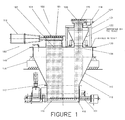
- FIG. 1 discloses an example of a weight-loss weigh feeder system 100 that operates in the presence of internal pressure.
- the weight-loss weigh feeder system 100 may be installed as part of a contained materials-handling system that can be sealed for dust containment.
- the system 100 includes a flexible gas purge line 140 that provides gas pressurization of a container (e.g., vessel, hopper, or tank) 110 capable of accommodating product supply.
- the flexible gas purge line 140 can be located anywhere on an upper portion of the system 100, the container 110, or the lower conical portion 122 of the pressure-compensator 121.
- the container 110 is affixed to a scale 130.
- the system 100 includes a metering mechanism 101 that provides discharge of product from the container 110.
- the system 100 includes a pressure-compensator 121 that is affixed to the scale.
- the pressure-compensator 121 operates to minimize or eliminate the effect of internal pressure in the container 110 on the scale 130 during weight sensing operations. For example, when pressure in the container is present, the pressure-compensator 121 operates to equalize internal pressure forces exerted on the scale 130 and thereby minimizes or eliminates inaccurate weighing of product supply in container 110 that can occur otherwise.
- a product-supply inlet 102 and a vent connection 106 are provided and allow internal pressure in the container to extend out to fixed surfaces 104, 108 respectively. Fixed surfaces 104, 108 are off the scale.
- the product-supply inlet 102 is attached to a product-refill mechanism 180 that typically includes an actuator 112 and a product-supply inlet valve 181.
- a vent shut-off valve 115 and a vent shut-off valve actuator 114 are located adjacent to the pressure-compensator 121. Actuator 114 acts to move valve 115 between an open position and a closed position.
- the product-refill mechanism 180 and vent valve actuator 114 cooperate together to provide for adding product in the container 110 when the product reaches a low level.
- the vent shut-off valve 115 opens to allow venting of gas from the container 110.
- the actuator 112 then activates, valve 181 opens, and product is added to the container 110 at inlet 102.
- the product-supply inlet valve 181 closes, and then vent shut-off valve 115 closes.
- Inert or other gas can be added via flexible gas purge line 140 to reestablish purge pressurization of the container 110.
- the product-refill mechanism 180 is mounted to a fixed surface 104 and is flexibly connected to the product-supply inlet 102 located on a cover 120 of the container 110 via flexible sleeve 131.
- the vent valve actuator 114 and vent shut-off valve 115 are mounted to a fixed surface 108.
- the vent connection 106 can be connected to a dust collection or exhaust system.
- the vent valve actuator 114 is attached to the vent shut-off valve 115.
- the vent shut-off valve 115 eliminates any potentially adverse effects of a vacuum draw (negative draw) on the container 110 that can be caused by a dust collection system.
- the vent connection 106 may be used to extract dust and displaced air from the container 110 when the container 110 is refilled with product through the product-supply inlet 102. As shown in the FIG. 1 example, the vent connection 106 extends through the pressure-compensator 121, which includes a conical lower portion 122 to direct product that may settle out of dust laden displaced air or other gas back into the container 110. In one implementation, the conical lower portion 122 of the pressure-compensator 121 is independently supported off the container 110.
- the pressure-compensator 121 includes an annular compensation ring 124, sized such that the surface area of the ring is identical to the sum of the cross sectional areas of the system's product-supply inlet 102 and vent connection 106.
- the compensation ring 124 operates to equalize the before-mentioned forces.
- One advantage of the compensation ring 124 is that it may minimize or negate the adverse effects of internal pressure (positive or negative) from affecting accurate weight sensing and, in turn, system performance.
- the pressure-compensator 121 is arranged as a pressure-balancing mechanism to ensure accurate weight sensing by scale 130 in the presence of an internal (purge) pressure.
- FIG 2 illustrates an example of pressure forces applied to the example weight-loss weigh feeder system of FIG 1.
- the pressure-compensator 121 is located in the vent connection 106 and has the conical lower portion 122 that directs the return of accumulated product back into the container 110 (i.e., dust that rises upward) while venting during a product refill operation.
- Example forces acting on the weigh feeder system due to pressurization are illustrated as arrows in FIG. 2. Positive forces that add (erroneously) to the weight measurement of product within the container 110 are illustrated with a "+” symbol. Negative forces that subtract from the weight measurement of product are illustrated with a "-” symbol. These negative forces counterbalance the positive forces mentioned previously. Static forces that neither add nor subtract weight have no symbol.
- the flexible gas purge line 140 provides purge gas to the interior of the container 110, but itself has no positive or negative influence on the scale 130.
- Flexible connectors or sleeves 131, 131a, 131b and 131c are provided to allow free movement of the weighing system in response to changes of weight (e.g., material) within the container 110, and are gas impermeable.
- weight e.g., material
- the purge gas contained within the container 110 can not escape into the surrounding atmosphere and the flexible sleeves can create an airtight system when valves 181 and 115 are closed.
- the compensation ring 124 of the pressure-compensator 121 is attached directly to the container cover 120 of the container 110 by elements 121.
- the compensation ring 124 is exposed to the contents of container 110 and may be attached to any location on the container cover 120.
- the internal purge pressure imparts an upward force on the compensation ring 124 equal to the downward force on the opposite portions of container 110 at locations 116, 117, 118 and 119. Since the compensation ring 124 is mounted to the container 110 of the system 100 by attachment to cover 120, the upward force on ring 124 is transferred directly to the container 110.
- the conical lower portion 122 of the pressure-compensator 121 is supported off the scale 130.
- the compensation ring 124 can continuously negate any adverse effects that pressure (internal to the container) would have upon weight sensing, and system performance.
Landscapes
- Physics & Mathematics (AREA)
- General Physics & Mathematics (AREA)
- Weight Measurement For Supplying Or Discharging Of Specified Amounts Of Material (AREA)
- Measuring Volume Flow (AREA)
Applications Claiming Priority (1)
| Application Number | Priority Date | Filing Date | Title |
|---|---|---|---|
| US10/931,556 US7191919B2 (en) | 2004-09-01 | 2004-09-01 | Weight-loss weigh feeder with pressure compensation |
Publications (2)
| Publication Number | Publication Date |
|---|---|
| EP1632759A2 true EP1632759A2 (de) | 2006-03-08 |
| EP1632759A3 EP1632759A3 (de) | 2011-11-30 |
Family
ID=35207743
Family Applications (1)
| Application Number | Title | Priority Date | Filing Date |
|---|---|---|---|
| EP05255221A Withdrawn EP1632759A3 (de) | 2004-09-01 | 2005-08-25 | Differentialsdosierwaage mit Druckkompensator. |
Country Status (3)
| Country | Link |
|---|---|
| US (1) | US7191919B2 (de) |
| EP (1) | EP1632759A3 (de) |
| CA (1) | CA2515478C (de) |
Cited By (1)
| Publication number | Priority date | Publication date | Assignee | Title |
|---|---|---|---|---|
| EP3945295A1 (de) * | 2020-07-28 | 2022-02-02 | HOSOKAWA ALPINE Aktiengesellschaft | Vorrichtung zur druckkompensation bei differentialdosiergeräten |
Families Citing this family (9)
| Publication number | Priority date | Publication date | Assignee | Title |
|---|---|---|---|---|
| US20070115928A1 (en) * | 2005-11-08 | 2007-05-24 | Benco David S | Network support for enhanced VoIP caller ID |
| US7534970B2 (en) | 2006-06-15 | 2009-05-19 | Schenck Accurate, Inc. | Counterbalanced dispensing system |
| CN105263697B (zh) | 2013-04-08 | 2017-07-14 | 国际热化学恢复股份有限公司 | 具有带多缸体液压回路的压缩阶段的液压进给系统 |
| CN104713620B (zh) * | 2013-12-17 | 2017-12-19 | 上海梅山钢铁股份有限公司 | 冶金炉料给料控制装置及控制方法 |
| EP3491347B1 (de) * | 2016-07-27 | 2020-02-12 | Bühler AG | Dosier- und wiegevorrichtung und verfahren zur bestimmung des gewichts eines produktes in einer dosier- und wiegevorrichtung |
| CN106757407A (zh) * | 2017-02-21 | 2017-05-31 | 无锡正佳自控系统股份有限公司 | 一种双失重秤 |
| US20210207990A1 (en) * | 2018-05-29 | 2021-07-08 | Basf Coatings Gmbh | Container comprising a valve head for pneumatic dosing and dosing facility comprising such a container |
| CN115468638B (zh) * | 2022-09-02 | 2025-02-18 | 中国矿业大学 | 一种减少失重秤用螺旋输送物料出料波动方法和系统 |
| CN120607129A (zh) * | 2025-08-11 | 2025-09-09 | 江苏百灵衡器制造有限公司 | 用于失重秤落料仓的粉尘收集结构 |
Family Cites Families (9)
| Publication number | Priority date | Publication date | Assignee | Title |
|---|---|---|---|---|
| CH650849A5 (de) * | 1981-02-23 | 1985-08-15 | K Tron Soder Ag | Zum aufstellen auf eine waage bestimmter, im wesentlichen geschlossener behaelter mit einem zur zuleitung von schutzgas dienenden, ins behaelterinnere muendenden druckgasanschluss. |
| CH658724A5 (en) * | 1982-12-17 | 1986-11-28 | K Tron Soder Ag | Metering balance |
| US4579252A (en) | 1983-05-05 | 1986-04-01 | K-Tron International, Inc. | Loss-in-weight gravimetric feeder |
| US4702393A (en) | 1985-02-07 | 1987-10-27 | Hyperion, Inc. | Compensating diluter/dispenser |
| US4867343A (en) | 1988-02-18 | 1989-09-19 | Acrison, Inc. | Wild-flow loss-in-weight weighing system |
| DE4332030A1 (de) * | 1993-09-21 | 1995-03-23 | Pfister Gmbh | Verfahren und Vorrichtung zum gravimetrischen Dosieren von Schüttgütern |
| US6168305B1 (en) * | 1998-02-27 | 2001-01-02 | Merrick Industries, Inc. | System for precisely controlling discharge rates for loss-in-weight feeder systems |
| US5992686A (en) | 1998-02-27 | 1999-11-30 | Fluid Research Corporation | Method and apparatus for dispensing liquids and solids |
| US20040002789A1 (en) * | 2002-07-01 | 2004-01-01 | Hachtel Robert George | Loss-in-weight feeder with discharge pressure compensator |
-
2004
- 2004-09-01 US US10/931,556 patent/US7191919B2/en not_active Expired - Lifetime
-
2005
- 2005-08-09 CA CA2515478A patent/CA2515478C/en not_active Expired - Lifetime
- 2005-08-25 EP EP05255221A patent/EP1632759A3/de not_active Withdrawn
Cited By (1)
| Publication number | Priority date | Publication date | Assignee | Title |
|---|---|---|---|---|
| EP3945295A1 (de) * | 2020-07-28 | 2022-02-02 | HOSOKAWA ALPINE Aktiengesellschaft | Vorrichtung zur druckkompensation bei differentialdosiergeräten |
Also Published As
| Publication number | Publication date |
|---|---|
| CA2515478A1 (en) | 2006-03-01 |
| US20060043104A1 (en) | 2006-03-02 |
| US7191919B2 (en) | 2007-03-20 |
| CA2515478C (en) | 2016-02-16 |
| EP1632759A3 (de) | 2011-11-30 |
Similar Documents
| Publication | Publication Date | Title |
|---|---|---|
| EP1632759A2 (de) | Differentialsdosierwaage mit Druckkompensator. | |
| CA2469267C (en) | Method and apparatus for gravimetric dosing bulk material | |
| US5520209A (en) | Fluid relief device | |
| US5165445A (en) | Relief vent apparatus | |
| MY109544A (en) | Gas purge system for isolation enclosure for contamination sensitive items. | |
| EP1200886A1 (de) | Druckregeleinrichtung für eine rohrleitung | |
| US6588458B2 (en) | System, apparatus and method for measuring and transferring the contents of a vessel | |
| US4134466A (en) | Weigh jet assemblies | |
| ATE99259T1 (de) | Vorrichtung zum spenden eines produktes unter konstantem druck. | |
| KR102567662B1 (ko) | 압력 정량 충진이 가능한 유체 주입 장치 | |
| CN113418666A (zh) | 一种包含气体缓冲和冲击测试结构的密封性能测试仪 | |
| JP2006176197A (ja) | タンク内圧力調整弁装置 | |
| US4494678A (en) | Apparatus for compensating a pressurized vessel on a scale | |
| CN209858349U (zh) | 一种罐盖耐压试漏仪 | |
| US20210164620A1 (en) | Liquid transfer apparatus | |
| CN210965028U (zh) | 一种抗氧剂自动添加装置及反应系统 | |
| KR840002511A (ko) | 균형화된 압력 결합장치 | |
| JP4320923B2 (ja) | ガラス固化体の重量測定装置及び重量測定方法 | |
| CN112105715B (zh) | 用于给生物反应器供气的方法和供气系统 | |
| CN208887755U (zh) | 一种用于易挥发液体的称量装置 | |
| US5635681A (en) | System for weighing radioactive materials | |
| CN219647453U (zh) | 压力平衡装置和反应设备 | |
| AU2019335850B2 (en) | Device for incubating cultures, method for incubating cultures and use | |
| CN207061849U (zh) | 一种液体输送装置 | |
| Hart et al. | Incorporating more gas control within cylinders |
Legal Events
| Date | Code | Title | Description |
|---|---|---|---|
| PUAI | Public reference made under article 153(3) epc to a published international application that has entered the european phase |
Free format text: ORIGINAL CODE: 0009012 |
|
| 17P | Request for examination filed |
Effective date: 20050914 |
|
| AK | Designated contracting states |
Kind code of ref document: A2 Designated state(s): AT BE BG CH CY CZ DE DK EE ES FI FR GB GR HU IE IS IT LI LT LU LV MC NL PL PT RO SE SI SK TR |
|
| AX | Request for extension of the european patent |
Extension state: AL BA HR MK YU |
|
| PUAL | Search report despatched |
Free format text: ORIGINAL CODE: 0009013 |
|
| AK | Designated contracting states |
Kind code of ref document: A3 Designated state(s): AT BE BG CH CY CZ DE DK EE ES FI FR GB GR HU IE IS IT LI LT LU LV MC NL PL PT RO SE SI SK TR |
|
| AX | Request for extension of the european patent |
Extension state: AL BA HR MK YU |
|
| RIC1 | Information provided on ipc code assigned before grant |
Ipc: G05D 7/06 20060101ALI20111026BHEP Ipc: G01G 11/08 20060101AFI20111026BHEP |
|
| AKX | Designation fees paid |
Designated state(s): AT BE BG CH CY CZ DE DK EE ES FI FR GB GR HU IE IS IT LI LT LU LV MC NL PL PT RO SE SI SK TR |
|
| STAA | Information on the status of an ep patent application or granted ep patent |
Free format text: STATUS: THE APPLICATION IS DEEMED TO BE WITHDRAWN |
|
| 18D | Application deemed to be withdrawn |
Effective date: 20120531 |