EP1632624B1 - Schloss mit Gegendrehmomentsicherheitsvorrichtung - Google Patents
Schloss mit Gegendrehmomentsicherheitsvorrichtung Download PDFInfo
- Publication number
- EP1632624B1 EP1632624B1 EP05107951A EP05107951A EP1632624B1 EP 1632624 B1 EP1632624 B1 EP 1632624B1 EP 05107951 A EP05107951 A EP 05107951A EP 05107951 A EP05107951 A EP 05107951A EP 1632624 B1 EP1632624 B1 EP 1632624B1
- Authority
- EP
- European Patent Office
- Prior art keywords
- cylinder
- distal end
- lock
- bush
- teeth
- Prior art date
- Legal status (The legal status is an assumption and is not a legal conclusion. Google has not performed a legal analysis and makes no representation as to the accuracy of the status listed.)
- Expired - Lifetime
Links
Images


Classifications
-
- E—FIXED CONSTRUCTIONS
- E05—LOCKS; KEYS; WINDOW OR DOOR FITTINGS; SAFES
- E05B—LOCKS; ACCESSORIES THEREFOR; HANDCUFFS
- E05B17/00—Accessories in connection with locks
- E05B17/0054—Fraction or shear lines; Slip-clutches, resilient parts or the like for preventing damage when forced or slammed
- E05B17/0062—Fraction or shear lines; Slip-clutches, resilient parts or the like for preventing damage when forced or slammed with destructive disengagement
-
- E—FIXED CONSTRUCTIONS
- E05—LOCKS; KEYS; WINDOW OR DOOR FITTINGS; SAFES
- E05B—LOCKS; ACCESSORIES THEREFOR; HANDCUFFS
- E05B17/00—Accessories in connection with locks
- E05B17/04—Devices for coupling the turning cylinder of a single or a double cylinder lock with the bolt operating member
-
- E—FIXED CONSTRUCTIONS
- E05—LOCKS; KEYS; WINDOW OR DOOR FITTINGS; SAFES
- E05B—LOCKS; ACCESSORIES THEREFOR; HANDCUFFS
- E05B9/00—Lock casings or latch-mechanism casings ; Fastening locks or fasteners or parts thereof to the wing
- E05B9/04—Casings of cylinder locks
- E05B2009/047—Means for returning cylinder locks to their neutral position
-
- E—FIXED CONSTRUCTIONS
- E05—LOCKS; KEYS; WINDOW OR DOOR FITTINGS; SAFES
- E05B—LOCKS; ACCESSORIES THEREFOR; HANDCUFFS
- E05B9/00—Lock casings or latch-mechanism casings ; Fastening locks or fasteners or parts thereof to the wing
- E05B9/04—Casings of cylinder locks
Definitions
- the present invention relates to a lock, particularly for a motor vehicle door.
- this lock comprises:
- the interference existing in a circumferential direction between these teeth reduces or preferably eliminates the possibility of the cylinder being rotated about the axis of the cavity of the bush, when the cylinder, as normally happens in break-ins, is forced axially inwards.
- This interference therefore makes impossible to forcibly turn the cylinder, when acting from the outside, and thus to move the bolt operating member without authorization.
- the lock to which the anti-torque security device of the present invention is fitted may also have other security devices, e.g. of the type in which, during attempted break-ins, a component is expelled in a radial direction in such a way as to break the continuity of the mechanism for transmitting movement from the proximal end of the cylinder to the bolt.
- the level of security of the lock is greatly enhanced.
- the anti-torque security device of the present invention can also be used as a single security device for a lock.
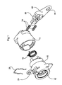
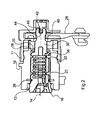
- a lock particularly for a motor vehicle door, comprises ( Figs. 1 and 2 ) a fixed bush 10 with a sleeve 11 attached to its distal end like an extension.
- the bush 10 defines internally a cylindrical cavity 12 about whose axis 14 there rotates a cylinder 16 which is fitted with a restoring spring 18 and has a first weakened cross section 20 and a second weakened section 22 close to its proximal and distal ends respectively.
- a slot 24 Around a circumferential section of the proximal portion of the bush 10 is a slot 24 able to house cylinder 16 retention means in the form of an inverted U-shaped spring 26.
- the spring 26 prevents, in normal operation of the lock, translational movement of the cylinder 16 in an axial direction, once the cylinder has been inserted into the cavity 12.
- the cylinder 16 is able to turn about the axis 14 when the appropriate key is inserted into the keyway.
- the lock also includes an operating member 28 for operating a bolt (which in itself is conventional and not illustrated in the figures), which member 28 is controlled by a nose 30 that protrudes from the distal end of the cylinder 16 and passes through a central opening defined by an annular flange 32 located at the distal end of the bush 10.
- the operating member 28 is also acted upon by springs 34 which react against a fixed surface of the sleeve 11.
- the nose 30 of the cylinder 16 has, at its distal end, an enlarged portion 40 which is followed by, when proceeding towards the proximal end, a portion 42 whose cross section is smaller than that of the enlarged portion 40 and therefore recessed compared with the latter.
- the portion 40 is of polygonal, in particular rectangular section and is engaged in a slot 44 of complementary shape formed in a plate 46 integral with the operating member 28, so as to transmit a torque.
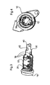
- the weakened first section 20 of the cylinder 16 is broken first of all ( Fig. 5 ), causing detachment of the proximal part 48 which then has to be extracted to allow access to the remaining part.
- the thief typically plying his trade with a tool such as a screwdriver or the like, will then push the remaining part of the cylinder 16 into the bush 10.
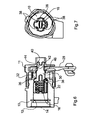
- This movement ( Figs. 6 and 7 ) has the effect of causing the teeth 36, 38 protruding from the adjacent surfaces of the distal end of the cylinder 16 and of the annular flange 32 to interlock with each other and form a continuous annular structure.
- the distal portion 52 of the cylinder 16 still inside the bush 10 is therefore irreversibly locked inside it and cannot be returned to its original position in which it turns freely.
- the portions of narrower cross section 42 of the nose 30 of the cylinder 16 could be circular so that no torque can be transmitted once it is in the slot 44 of the plate 46 integral with the operating member 28 following an attempted break-in.
- This detail further enhances the locks' security because, even in the hypothetical event that the thief manages to turn the cylinder 16 by overcoming the resistance presented by the interlocking of the teeth 36, 38, the circular-section portion 42 of the nose 30 would rotate idly inside the slot 44 and could not therefore produce any movement in the operating member 28.
Landscapes
- Lock And Its Accessories (AREA)
Claims (5)
- Schloss, insbesondere für eine Kraftfahrzeugtür, enthaltend:- eine feststehende Buchse (10), die einen zylindrischen Hohlraum (12) definiert, in dem sich ein Zylinder (16) um die Achse (14) des Hohlraumes (12) dreht, und- ein Bolzenbetätigungselement (28), das von einer Nase (30) gesteuert wird, die am distalen Ende des Zylinders (16) hervorragt und eine zentrale Öffnung durchläuft, die von einem ringförmigen Flansch (32) gebildet ist, der sich am distalen Ende der Buchse (10) befindet,wobei das Schloss dadurch gekennzeichnet ist, dass wenigstens ein jeweiliger sich axial erstreckender Zahn (36, 38) von den zugewandten Oberflächen des distalen Endes des Zylinders (16) und des ringförmigen Flansches (32) hervorsteht, wobei diese Zähne (36, 38) in der Lage sind, miteinander in Eingriff zu gelangen, und somit verhindern, dass, wenn ein Dieb das Lösen des proximalen Teils (48) des Zylinders (16) bewirkt, sich der übrige Teil des Zylinders (16) dreht, wenn der übrige Teil des Zylinders (16) zum distalen Ende der Buchse (10) geschoben wird.
- Schloss nach Anspruch 1, dadurch gekennzeichnet, dass jeweilige Vielzahlen von in Umfangsrichtung beabstandeten Zähnen (36, 38) von den benachbarten Oberflächen des distalen Endes des Zylinders (16) und vom ringförmigen Flansch (32) hervorragen, wobei die Zähne (36, 38) jeder Vielzahl im Bezug auf jene (38, 36) der anderen Vielzahl derart gestaffelt sind, dass die Bewegung des übrigen Teils des Zylinders (16) zum distalen Ende der Buchse (10) infolge des Ineinandergreifens der Zähne (36, 38) die Ausbildung einer kontinuierlichen ringförmigen Struktur bewirkt.
- Schloss nach einem der vorhergehenden Ansprüche, dadurch gekennzeichnet, dass der Zylinder (16) einen ersten geschwächten Querschnitt (20) und einen zweiten geschwächten Querschnitt (22) in der Nähe seines proximalen bzw. distalen Endes hat.
- Schloss nach einem der vorhergehenden Ansprüche, dadurch gekennzeichnet, dass die Nase (30) an ihrem distalen Ende einen vergrößerten Abschnitt (40) aufweist, dessen Umriss einen polygonalen Querschnitt hat, und der im normalen Betätigungszustand in einen Schlitz (44) komplementärer Form in einer Platte (46) eingreift, die integraler Bestandteil des Betätigungselementes (28) ist, so dass ein Drehmoment übertragen wird.
- Schloss nach Anspruch 4, dadurch gekennzeichnet, dass die Nase (30) unmittelbar hinter dem vergrößerten Abschnitt (40), wenn man zum proximalen Ende fortschreitet, einen Abschnitt (40) mit kreisförmigem Querschnitt (42) hat, der im Vergleich mit dem vergrößerten Abschnitt (40) ausgenommen ist, wobei der ausgenommene Abschnitt (42) in der Lage ist, wenn der Zylinder (16) zum distalen Ende der Buchse (10) geschoben wird, in den Schlitz (44) einzutreten, in dem er sich frei drehen kann, ohne ein Drehmoment zu übertragen.
Applications Claiming Priority (1)
| Application Number | Priority Date | Filing Date | Title |
|---|---|---|---|
| ITTO20040584 ITTO20040584A1 (it) | 2004-09-03 | 2004-09-03 | Serratura con dispositivo di sicurezza antitorsione |
Publications (3)
| Publication Number | Publication Date |
|---|---|
| EP1632624A2 EP1632624A2 (de) | 2006-03-08 |
| EP1632624A3 EP1632624A3 (de) | 2007-05-09 |
| EP1632624B1 true EP1632624B1 (de) | 2009-07-01 |
Family
ID=35045313
Family Applications (1)
| Application Number | Title | Priority Date | Filing Date |
|---|---|---|---|
| EP05107951A Expired - Lifetime EP1632624B1 (de) | 2004-09-03 | 2005-08-31 | Schloss mit Gegendrehmomentsicherheitsvorrichtung |
Country Status (3)
| Country | Link |
|---|---|
| EP (1) | EP1632624B1 (de) |
| DE (1) | DE602005015170D1 (de) |
| IT (1) | ITTO20040584A1 (de) |
Families Citing this family (5)
| Publication number | Priority date | Publication date | Assignee | Title |
|---|---|---|---|---|
| AT501753B1 (de) * | 2006-02-22 | 2006-11-15 | Evva Werke | Sicherheitseinrichtung für schlösser |
| IT1390918B1 (it) * | 2008-09-29 | 2011-10-19 | Giobert Spa | Serratura di sicurezza. |
| IL212128A (en) * | 2011-04-04 | 2016-04-21 | Mul T Lock Technologies Ltd | Anti-breakage cylinder lock assembly |
| JP6334849B2 (ja) * | 2013-06-03 | 2018-05-30 | 株式会社アルファ | シリンダ錠 |
| FR3026768B1 (fr) * | 2014-10-01 | 2019-05-17 | U-Shin France | Verrou pour mecanisme de serrure de vehicule automobile |
Family Cites Families (3)
| Publication number | Priority date | Publication date | Assignee | Title |
|---|---|---|---|---|
| US2004434A (en) * | 1934-11-05 | 1935-06-11 | Briggs & Stratton Corp | Lock |
| DE2748408C2 (de) * | 1977-10-28 | 1986-11-20 | Daimler-Benz Ag, 7000 Stuttgart | Schließzylinder, insbesondere für Kraftfahrzeuge |
| FR2676490B1 (fr) * | 1991-05-14 | 1993-09-17 | Fichet Bauche | Dispositif de surete apte a realiser un blocage du barillet en cas de tentative de forcage et mecanisme de serrure equipe de ce dispositif. |
-
2004
- 2004-09-03 IT ITTO20040584 patent/ITTO20040584A1/it unknown
-
2005
- 2005-08-31 DE DE602005015170T patent/DE602005015170D1/de not_active Expired - Lifetime
- 2005-08-31 EP EP05107951A patent/EP1632624B1/de not_active Expired - Lifetime
Also Published As
| Publication number | Publication date |
|---|---|
| EP1632624A3 (de) | 2007-05-09 |
| EP1632624A2 (de) | 2006-03-08 |
| ITTO20040584A1 (it) | 2004-12-03 |
| DE602005015170D1 (de) | 2009-08-13 |
Similar Documents
| Publication | Publication Date | Title |
|---|---|---|
| US6978645B2 (en) | Freewheeling lock apparatus and method | |
| US6711924B2 (en) | Freewheeling lock apparatus and method | |
| RU2528156C2 (ru) | Замковый механизм | |
| EP2494129B1 (de) | Verriegelungsmechanismus | |
| CN1075588C (zh) | 一种带闭锁圆柱的锁定装置 | |
| CN101743368B (zh) | 锁组件 | |
| KR20190123769A (ko) | 가역 클러치 모티스록 | |
| US4233913A (en) | Safe door | |
| EP1632624A2 (de) | Schloss mit Gegendrehmomentsicherheitsvorrichtung | |
| EP0049050B1 (de) | Zylinderschloss | |
| EP1149220B1 (de) | Zylinderschloss | |
| EP3733999B1 (de) | Doppelzylinderschlossanordnung | |
| EP0640733B1 (de) | Befestigung eines Zylinderschlosses an einer Fahrzeugtür | |
| CN120925713A (zh) | 锁闭装置 | |
| WO2021251895A1 (en) | Adapter for a locking device, and locking assembly comprising an adapter and a locking device | |
| EP2169151B1 (de) | Sicherheitsschloss | |
| US20060191304A1 (en) | Door lock system | |
| EP3959400B1 (de) | Zylinderschloss mit verbesserter festigkeit | |
| EP4248040B1 (de) | Schlossaktuator | |
| JP2906185B2 (ja) | シリンダ錠 | |
| GB2638702A (en) | High security lock cylinder | |
| KR100921877B1 (ko) | 차량의 도난 방지용 도어락 구조 | |
| CN122029332A (zh) | 锁芯 | |
| CA3118283A1 (en) | Cylinder lock | |
| HK1037704A1 (en) | Door lock assembly with detachable operating handle |
Legal Events
| Date | Code | Title | Description |
|---|---|---|---|
| PUAI | Public reference made under article 153(3) epc to a published international application that has entered the european phase |
Free format text: ORIGINAL CODE: 0009012 |
|
| AK | Designated contracting states |
Kind code of ref document: A2 Designated state(s): AT BE BG CH CY CZ DE DK EE ES FI FR GB GR HU IE IS IT LI LT LU LV MC NL PL PT RO SE SI SK TR |
|
| AX | Request for extension of the european patent |
Extension state: AL BA HR MK YU |
|
| PUAL | Search report despatched |
Free format text: ORIGINAL CODE: 0009013 |
|
| AK | Designated contracting states |
Kind code of ref document: A3 Designated state(s): AT BE BG CH CY CZ DE DK EE ES FI FR GB GR HU IE IS IT LI LT LU LV MC NL PL PT RO SE SI SK TR |
|
| AX | Request for extension of the european patent |
Extension state: AL BA HR MK YU |
|
| 17P | Request for examination filed |
Effective date: 20071106 |
|
| 17Q | First examination report despatched |
Effective date: 20071213 |
|
| AKX | Designation fees paid |
Designated state(s): DE FR GB |
|
| GRAP | Despatch of communication of intention to grant a patent |
Free format text: ORIGINAL CODE: EPIDOSNIGR1 |
|
| GRAS | Grant fee paid |
Free format text: ORIGINAL CODE: EPIDOSNIGR3 |
|
| GRAA | (expected) grant |
Free format text: ORIGINAL CODE: 0009210 |
|
| RAP1 | Party data changed (applicant data changed or rights of an application transferred) |
Owner name: GIOBERT S.P.A. |
|
| AK | Designated contracting states |
Kind code of ref document: B1 Designated state(s): DE FR GB |
|
| REG | Reference to a national code |
Ref country code: GB Ref legal event code: FG4D |
|
| REF | Corresponds to: |
Ref document number: 602005015170 Country of ref document: DE Date of ref document: 20090813 Kind code of ref document: P |
|
| PLBE | No opposition filed within time limit |
Free format text: ORIGINAL CODE: 0009261 |
|
| STAA | Information on the status of an ep patent application or granted ep patent |
Free format text: STATUS: NO OPPOSITION FILED WITHIN TIME LIMIT |
|
| 26N | No opposition filed |
Effective date: 20100406 |
|
| REG | Reference to a national code |
Ref country code: FR Ref legal event code: PLFP Year of fee payment: 12 |
|
| REG | Reference to a national code |
Ref country code: FR Ref legal event code: PLFP Year of fee payment: 13 |
|
| REG | Reference to a national code |
Ref country code: FR Ref legal event code: PLFP Year of fee payment: 14 |
|
| PGFP | Annual fee paid to national office [announced via postgrant information from national office to epo] |
Ref country code: DE Payment date: 20190830 Year of fee payment: 15 Ref country code: FR Payment date: 20190830 Year of fee payment: 15 |
|
| PGFP | Annual fee paid to national office [announced via postgrant information from national office to epo] |
Ref country code: GB Payment date: 20190821 Year of fee payment: 15 |
|
| REG | Reference to a national code |
Ref country code: DE Ref legal event code: R119 Ref document number: 602005015170 Country of ref document: DE |
|
| GBPC | Gb: european patent ceased through non-payment of renewal fee |
Effective date: 20200831 |
|
| PG25 | Lapsed in a contracting state [announced via postgrant information from national office to epo] |
Ref country code: FR Free format text: LAPSE BECAUSE OF NON-PAYMENT OF DUE FEES Effective date: 20200831 Ref country code: DE Free format text: LAPSE BECAUSE OF NON-PAYMENT OF DUE FEES Effective date: 20210302 |
|
| PG25 | Lapsed in a contracting state [announced via postgrant information from national office to epo] |
Ref country code: GB Free format text: LAPSE BECAUSE OF NON-PAYMENT OF DUE FEES Effective date: 20200831 |