EP1632417A1 - Steering device - Google Patents
Steering device Download PDFInfo
- Publication number
- EP1632417A1 EP1632417A1 EP05017533A EP05017533A EP1632417A1 EP 1632417 A1 EP1632417 A1 EP 1632417A1 EP 05017533 A EP05017533 A EP 05017533A EP 05017533 A EP05017533 A EP 05017533A EP 1632417 A1 EP1632417 A1 EP 1632417A1
- Authority
- EP
- European Patent Office
- Prior art keywords
- actuator
- steering
- case
- rubber boot
- steering device
- Prior art date
- Legal status (The legal status is an assumption and is not a legal conclusion. Google has not performed a legal analysis and makes no representation as to the accuracy of the status listed.)
- Granted
Links
Images


Classifications
-
- B—PERFORMING OPERATIONS; TRANSPORTING
- B60—VEHICLES IN GENERAL
- B60R—VEHICLES, VEHICLE FITTINGS, OR VEHICLE PARTS, NOT OTHERWISE PROVIDED FOR
- B60R13/00—Elements for body-finishing, identifying, or decorating; Arrangements or adaptations for advertising purposes
- B60R13/02—Internal Trim mouldings ; Internal Ledges; Wall liners for passenger compartments; Roof liners
- B60R13/0256—Dashboard liners
-
- B—PERFORMING OPERATIONS; TRANSPORTING
- B60—VEHICLES IN GENERAL
- B60R—VEHICLES, VEHICLE FITTINGS, OR VEHICLE PARTS, NOT OTHERWISE PROVIDED FOR
- B60R13/00—Elements for body-finishing, identifying, or decorating; Arrangements or adaptations for advertising purposes
- B60R13/08—Insulating elements, e.g. for sound insulation
- B60R13/0846—Insulating elements, e.g. for sound insulation for duct, cable or rod passages, e.g. between engine and passenger compartments
- B60R13/0853—Insulating elements, e.g. for sound insulation for duct, cable or rod passages, e.g. between engine and passenger compartments specially adapted for movable parts, e.g. gears levers, pedals
-
- B—PERFORMING OPERATIONS; TRANSPORTING
- B62—LAND VEHICLES FOR TRAVELLING OTHERWISE THAN ON RAILS
- B62D—MOTOR VEHICLES; TRAILERS
- B62D1/00—Steering controls, i.e. means for initiating a change of direction of the vehicle
- B62D1/02—Steering controls, i.e. means for initiating a change of direction of the vehicle vehicle-mounted
- B62D1/16—Steering columns
- B62D1/166—Means changing the transfer ratio between steering wheel and steering gear
Definitions
- the present invention relates to a steering device provided with an actuator at an intermediate portion of a steering shaft extending downward from a steering handle for altering the transmission ratio in rotation between upper and lower portions of the steering shaft in dependence on the traveling state.
- a cable case of a double cylinder structure wherein a case inner component composing an inner member of the cable case is fixed to the actuator, whereas a case outer component composing an outer member of the cable case is fixed to the vehicle body.
- a spiral cable constructed by winding a flat cable is housed inside the cable case and is fixed to the case inner component at one end thereof and to the case outer component at the other end thereof. Further, an external cable electrically connected to the spiral cable is stretched between the case outer component and the vehicle body, and the supplying of electric power is performed through the external cable and the spiral cable.
- the winding state of the spiral cable changes between the case outer component and the case inner component, so that a load added by the manipulation of the steering handle is not applied to the external cable.
- the reaction force to the cable upon the manipulation of the steering handle is suppressed to improve the endurance of the cable.
- FIG 13 shows a prior art steering device.
- a clip 2 is provided at an intermediate portion of an external cable 1 to be fixed to the vehicle body (not shown).
- a case outer component 5 is secured against rotation relative to the vehicle body by extending a wire 4 of a V-letter shape from a wire hook 3 integrally formed on the clip 2 and by fixing opposite ends of the V-letter shape wire 4 to two portions on the circumferential surface of the case outer component 5.
- Another object of the present invention is to provide an improved steering device capable of being assembled to a vehicle body without damaging a rubber boot covering an actuator which is provided on an intermediate portion of a steering shaft for altering the transmission ratio in rotation from a steering handle to a steering gear unit.
- a steering device which comprises an actuator provided at an intermediate portion of a steering shaft extending downward from a steering handle to pass through a dashboard of a vehicle body for altering the transmission ratio in rotation between upper and lower portions of the steering shaft in dependence on the traveling state, a cable case of a double cylindrical structure arranged on an upper surface of the actuator, a case inner cylindrical component constituting the inside of the cable case and fixed to the actuator, and a case outer cylindrical component constituting the outside of the cable case and rotatable relative to the case inner cylindrical component.
- the steering device further comprises a spiral cable provided for supplying the actuator with electric power and housed inside the cable case with itself being wound, the spiral cable being fixed to the case inner cylindrical component at one end thereof and to the case outer cylindrical component at the other end thereof, and a cylindrical rubber boot covering the circumferential surface of the actuator.
- a spiral cable provided for supplying the actuator with electric power and housed inside the cable case with itself being wound, the spiral cable being fixed to the case inner cylindrical component at one end thereof and to the case outer cylindrical component at the other end thereof, and a cylindrical rubber boot covering the circumferential surface of the actuator.
- an upper side portion of the rubber boot is fixedly fitted on the case outer cylindrical component, and a lower side portion of the rubber boot is fixed to the dashboard.
- the case outer cylindrical component can be secured against rotation more firmly than that in the prior art steering device wherein two portions on a case outer cylindrical component are fixed with a wire of a V-letter shape. Further, the problem attendant on the wire of the V-letter shape in the prior art steering device no longer arises even in the car models wherein the case outer cylindrical component and the dashboard are relatively far from each other. That is, according to the present invention, it can be realized to firmly secure the case outer cylindrical component of the cable case against rotation relative to the vehicle body irrespective of car models.
- a steering device which comprises a first steering shaft extending downward from a steering handle, a second steering shaft extending upward from a steering gear unit between a pair of steerable wheels, and an actuator connected between the first and second steering shafts for transmitting rotation therebetween and being capable of altering the transmission ratio of the rotation in dependence on the traveling state:
- the steering device further comprises an input side connection shaft provided at an upper end portion of the actuator and connected to the first steering shaft through fitting engagement to be rotatable bodily therewith, an output side connection shaft protruding from the lower end surface of the actuator and connected to the second steering shaft through fitting engagement to be rotatable bodily therewith, a rubber boot covering the circumferential surface and the lower end surface of the actuator and allowing the output side connection shaft to pass through a portion thereof covering the lower end surface, the boot having an upper end portion fixedly fitted on the actuator, and a bracket for fixing an axial intermediate portion of the rubber boot to a dashboard of a vehicle body.
- the input side connection shaft and the first steering shaft are brought into face-to-face relation by moving the actuator downward as the rubber boot is deformed compressively, and are connected to each other through fitting engagement then by moving the actuator upward.
- the steering device is further provided with a cap made of a member which is higher in elasticity than another member composing a lower end corner portion of the actuator, for covering the lower end corner portion of the actuator.
- FIG. 1 shows a vehicle provided with a steering device 10 according to the present invention.
- a steering gear unit 69 is provided between a pair of front wheels 11, 11 (corresponding to steerable wheels in the present invention) provided on the vehicle.
- the steering gear unit 69 is of the structure that a pinion 15 is meshing with a rack 12 passing through a cylindrical rack case 12C.
- the rack case 12C is fixed a vehicle body 14, and the rack 12 is connected at its opposite ends to the respective front wheels 11, 11 through tie rods 13, 13.
- the pinion 15 and a steering handle 17 are connected through a steering shaft 90, and an actuator 18 is provided at an intermediate portion of the steering shaft 90.
- the steering shaft 90 is composed of a first steering shaft 74 (corresponding to an upper side portion of a steering shaft in the present invention) on the steering handle 17 side and a second steering shaft 70 (corresponding to a lower side portion of the steering shaft in the present invention) on the steering gear unit 69 side, and the actuator 18 is connected between the first and second steering shafts 74 and 70.
- the second steering shaft 70 is provided with a universal joint 71 at an intermediate portion thereof, and a base shaft 73A extending downward from the universal joint 71 is connected to the pinion 15 in axial alignment with the same, whereas a connection sleeve 73B extending upward from the universal joint 71 is tiltable relative to the base shaft 73A.
- the universal joint 71 is biforked at an upper end portion of the base shaft 73A as well as at a lower end portion of the connection sleeve 73B and is constructed so that a first shaft 73C whose opposite ends are carried on the base shaft 73A intersects perpendicularly with a second shaft 73D whose opposite ends are carried on the connection sleeve 73B.
- rotation can be transmitted between the base shaft 73A and the connection sleeve 73B with the rotational axes of the base shaft 73A and the connection sleeve 73B intersecting with each other at a certain angle.
- the connection sleeve 73B takes a cylindrical shape and has a spline formed at an internal surface thereof.
- a bolt 72 for shrinking the diameter of the connection sleeve 73B.
- a numeral 75 denotes a column assy (or assembly), which is attached to an installment panel reinforcement (not shown) provided in the vehicle body 14.
- the column assy 75 is able to vary its angle relative to the vehicle body 14 in a vertical direction, as applied in ordinary vehicles.
- the first steering shaft 74 is rotatably carried in the column assy 75.
- the steering handle 17 is removably attached to a portion (refer to Figure 3) protruding from the upper end of the column assy 75 of the first steering shaft 74. Further, the steering handle 17 is provided with an airbag 17A.
- the actuator 18 is provided with a differential type reduction gear 20 and an electric motor 25 for driving the reduction gear 20.
- a pair of outer rings 21, 22 are axially juxtaposed in the reduction gear 20.
- Each of the outer rings 21, 22 has plural fine teeth formed at its internal surface, and one of the outer rings 22 is set to be fewer by, e.g., one in tooth number than the other outer ring 21.
- An inner ring 23 is commonly fitted in the outer rings 21, 22 and is provided at a circumferential surface thereof with plural fine teeth being able to be meshed commonly with the teeth of the both outer rings 21, 22. Further, the inner ring 23 is formed to be ellipse or oval, so that a part of the teeth of the inner ring 23 is in meshing with parts of the teeth of the outer rings 21, 22.
- the motor 25 is arranged at an upper side of the reduction gear 20 in axial alignment with the same.
- a rotor 26 of the motor 25 is coupled to the inner ring 23 of the reduction gear 20 to be rotatable bodily.
- a stator 28 of the motor 25 and the outer ring 21 at the upper side are fixedly fitted in an assy sleeve 19.
- the outer ring 22 at the lower side is allowed to rotate relative to the assy sleeve 19.
- the outer ring 22 at the lower side is rotated faster than the outer ring 21 at the upper side because the former is fewer by one in tooth number than the latter. That is, the outer ring 22 is rotated slightly by an angle corresponding to one tooth upon one rotation of the inner ring 23, so that the speed reduction effect can be obtained between the motor 25 and the outer ring 22.
- the outer ring 22 is coupled to an output side connection shaft 16.
- the output side connection shaft 16 is composed of a first shaft component 16A of a pipe shape and a second shaft component 16B inserted into the lower end portion of the first shaft component 16A, and a coupling disc 24 is provided at the upper end portion of the first shaft component 16A.
- the coupling disc 24 is fixed to the outer ring 22 to be rotatable bodily therewith.
- the second shaft component 16B is provided at its upper end portion with a friction engagement portion 16C, which is urged to be pressured upon the lower end internal surface of the first shaft component 16A.
- the upper end portion of the second shaft component 16B is held on the lower end portion of the first shaft component 16A through the friction engagement between the friction engagement portion 16C and the lower end internal surface of the first shaft component 16A.
- an axis force which is greater than a predetermined value is axially applied on the output side connection shaft 16
- the second shaft component 16B is pushed into the first shaft component 16A, so that the output side connection shaft 16 becomes short as a whole.
- the friction force at the friction engagement portion 16C is adjustable by screw adjustment of a setting screw 16D provided at the friction engagement portion 16C.
- a closing cap 85 is attached to a lower end opening of the assy sleeve 19.
- the output side connection shaft 16 passes through the center of the closing cap 85.
- An oil seal 82 sticking firmly to the output side connection shaft 16 is provided at the internal surface of a portion of the closing cap 85 where the output side connection shaft 16 passes through.
- a position sensor 31 for detecting the rotational position of the rotor 26 is provided on the upper end portion of the motor 25.
- a rotary shaft 26S provided at the center of the rotor 26 protrudes from the upper end surface of the motor 25, and a lock disc 32 is fixed to a protruding portion of the rotary shaft 26S to be rotatable bodily therewith.
- a pillar 34 is upstanding at a position adjacent to the circumferential edge of the upper surface of the motor 25, and a lock arm 33 is pivotably carried on the pillar 34.
- the lock arm 33 is urged by a torsion spring 33C to be engaged with the lock disc 32 and is released from engagement with the lock disc 32 by energizing a solenoid 35 provided on the upper surface of the motor 25.
- a solenoid 35 provided on the upper surface of the motor 25.
- the upper end portion of the motor 25 is covered with a coupling housing 36.
- the coupling housing 36 is provided with a top plate portion 36A facing the upper surface of the motor 25, a large-diameter cylindrical portion 36B extending downward from the top plate portion 36A and a small-diameter cylindrical portion 36C extending upward from the top plate portion 36A.
- the lower end portion of the large-diameter cylindrical portion 36B is fixedly fitted on the upper end portion of the assy sleeve 19.
- the large-diameter cylindrical portion 36B is partly cut away to form a work window 36W.
- the work window 36W enables the terminal furniture 25X and the terminal furniture 25Y to face outside therethrough.
- the work window 36W is closed by means of an inside cylindrical member 43 referred to later.
- an input side connection shaft 78 is fixed to the inside bottom surface of the small-diameter cylindrical portion 36C.
- the input side connection shaft 78 is provided with a universal joint 79 at an intermediate portion thereof and is further composed of a base section 76 and a joint sleeve 77 respectively at lower and upper sides of the universal joint 79.
- the base section 76 takes a U-letter shape, and an embossment 76E protrudes from the lower surface of a plinth provided beneath the base section 76.
- the embossment 76E is fitted in a center hole formed in the inside bottom surface of the small-diameter cylindrical portion 36C to align the base section 76 with the axis of the actuator 18.
- the universal joint 79 is provided with a first shaft 76A whose opposite ends are carried on the base section 76 and a second shaft 76B rotatably carried and extending perpendicularly to the first shaft 76A, and the lower end portion of the joint sleeve 77 is fixed to the second shaft 76B.
- the base section 76 and the joint sleeve 77 are able to rotate bodily with a bent state being held between the base section 76 and the joint sleeve 77.
- the joint sleeve 77 is provided with a cylindrical space, whose internal surface has spine formed thereon.
- the first steering shaft 74 is spline-connected with the joint sleeve 77 by being inserted thereinto.
- a cable case 39 is assembled on the upper portion of the coupling housing 36.
- the cable case 39 is constituted by fitting a case inner cylindrical component 40 and a case outer cylindrical component 41 to be rotatable relatively.
- the case inner cylindrical component 40 takes a cylinder shape fixed to the small-diameter cylindrical portion 36C of the coupling housing 36 and protrudes a circular bottom wall 40A at the lower end portion thereof.
- the circular bottom wall 40A of the case inner cylindrical component 40 is fixed at the lower end surface thereof to the upper end portion of the inside cylindrical member 43, and the inside cylindrical member 43 closes the work window 36W of the coupling housing 36, as mentioned earlier.
- the case outer cylindrical component 41 takes a generally cylindrical shape which has a lager inner diameter than the circular bottom wall 40A to surround the whole of the case inner cylindrical component 40 and expands a wire leading section 41 D radially outward at a part of the circumferential surface thereof, as shown in Figure 7. Further, an upper end opening of the case outer cylindrical component 41 is closed with a ring cap 42, as shown in Figure 5. Additionally, a cylindrical wall 42A is suspended downward from the inner circumference of the ring cap 42, and the lower end portion of the cylindrical wall 42A is loosely fitted on the inside upper end portion of the case inner cylindrical component 40.
- a ring-like bottom wall 41A protrudes radially inwardly from the lower end portion of the case outer cylindrical component 41 to be overlapped with the circular bottom wall 40A, and a boot holder sleeve 41C of a generally cylindrical shape is suspended downward from the inner circumference of the ring-like bottom wall 41A.
- a portion of the boot holder sleeve 41C which portion corresponds to the work window 36W of the coupling housing 36 is partly cut away to form another work window 41W.
- a sheet metal ring 44 is fitted on the outer surface of the boot holder sleeve 41C.
- the work window 41W is closed with the sheet metal ring 44.
- a flange portion 41T is protruded radially outwardly from the lower end circumference of the boot holder sleeve 41C, and the sheet metal ring 44 engages at its lower end portion with the flange portion 41T.
- a spiral cable 45 is housed in an annular space defined between the case inner cylindrical component 40 and the case outer cylindrical component 41. Specifically, the spiral cable 45 is wound around a cylindrical portion of the case inner cylindrical component 40 and is secured to the case inner cylindrical component 40 at its inside terminal portion and to the wire leading section 41D of the case outer cylindrical component 41 at its outside terminal portion. Inside the wire leading section 41D, plural electric paths provided in the spiral cable 45 are connected to an external cable 52, which is led outside the cable case 39.
- Figure 8 is a bottom view of the cable case 39.
- the circular bottom wall 40A of the case inner cylindrical component 40 of the cable case 39 is provided thereon with plural terminal furniture 40X and 40Y respectively corresponding to the terminal furniture 25X for the motor 25 and the terminal furniture 25Y for the position sensor 31.
- These terminal furniture 40X, 40Y pass through the circular bottom wall 40A of the case inner cylindrical component 40 and are connected to plural electric paths provided in the spiral cable 45.
- the top plate portion 36A of the coupling housing 36 has a cutout 36F formed for allowing the terminal furniture 40X and 40Y (refer to Figure 8) to pass through in the vertical direction.
- the terminal furniture 40X, 40Y of the case inner cylindrical component 40 are brought into face-to-face relations respectively with the terminal furniture 25X for the motor 25 and the terminal furniture 25Y for the position sensor 31.
- the work windows 36W and 41W are kept opened, in which state the terminal furniture 40X, 40Y and the terminal furniture 25X, 25Y are brought into connection respectively while being observed through the work windows 36W and 41W.
- a first rubber boot 46 is attached to the boot holder sleeve 41C of the case outer cylindrical component 41.
- the first rubber boot 46 takes a cylindrical shape opened at opposite ends thereof and is fixed to the case outer cylindrical component 41 in such a manner that an upper end fitting portion 46A provided at the upper end is fitted on the outer surface of the sheet metal ring 44 fitted on the boot holder sleeve 41C and that then, a clamp ring 47 is clamped on the outer surface of the upper end fitting portion 46A.
- the upper end portion of the upper end fitting portion 46A radially outwardly extends a flange portion 46B for ensuring that the upper end fitting portion 46A is prevented from coming out therefrom.
- the first rubber boot 46 is formed at its lower end portion with a lower end fitting portion 46C which is approximately the same in diameter as the upper end fitting portion 46A and is provided between the upper and lower fitting portions 46A, 46C with a cylindrical body portion 46D whose diameter is larger than those of the fitting portions 46A, 46C.
- the cylindrical body portion 46D is constructed to join a pair of taper cylinders arranged in alignment vertically so that the center portion in the axial direction becomes largest in diameter.
- a bendable portion 46K having a ridge line 46R is formed at the center portion in the axial direction of the cylindrical body portion 46D.
- plural engaging protrusions 46L arranged circumferentially are formed on the internal surface at a boundary portion with the lower end fitting portion 46C of the cylindrical body portion 46D. More specifically, as shown in Figure 10, the engaging protrusions 46L are formed at six positions which equally divides the circumference of the first rubber boot 46.
- a flange portion 46E overhangs radially outwardly from the lower end circumference of the lower end fitting portion 46C.
- An inner metal sleeve 48 is inserted into the internal surface of the lower end fitting portion 46C.
- the inner metal sleeve 48 is prevented from coming out therefrom by engaging a flange portion 48A, which overhangs radially outwardly from the upper end portion thereof, with the inside upper circumferential edge portion of the lower end fitting portion 46C.
- the flange portion 48A has pit portions 48D formed at the six positions equally dividing the circumference thereof, and these pit portion 48D receives the engaging protrusions 46L therein thereby to secure the inner metal sleeve 48 against rotation relative to the first rubber boot 46.
- the inner metal sleeve 48 is fitted at its upper half in the lower end fitting portion 46C and protrudes its lower half downward from the lower end fitting portion 46C.
- a second rubber boot 49 has its upper end portion fitted on the lower half of the inner metal sleeve 48 and vulcanized to be adhered thereto.
- the first and second rubber boots 46, 49 are fixed bodily to constitute a rubber boot 120 in the present invention.
- the second rubber boot 49 takes a cylindrical shape opened at opposite ends thereof and is provided with a cylindrical body section 49A, a bellows section 49B and a seal section 49C in turn from top toward bottom.
- An outer metal sleeve 50 (corresponding to a metal sleeve in the present invention) is fitted on the outer surface of the body section 49A and is adhered to the body section 49A by vulcanizing the same.
- a flange portion 50A overhangs radially outwardly from the upper end portion of the outer metal sleeve 50, and a flange portion 49D overhangs radially outwardly from the upper end portion of the body section 49A to be overlapped over the flange portion 50A.
- the bellows section 49B as a whole decreases in diameter as it goes down and takes a so-called bellows construction that plural bendable portions 49E are provided at the intermediate portion in the axial direction.
- the seal section 49C is closely fitted on the circumferential surface of the output side connection shaft 16. However, when the output side connection shaft 16 is rotated in connection with the steering manipulation of the steering handle 17, the seal section 49C allows the output side connection shaft 16 to slidden thereon.
- a boot insertion bracket 101 for fixing the actuator 18 to a dashboard 100 of the vehicle body 14 is fitted and attached onto the outer surface of the outer metal sleeve 50.
- the boot insertion bracket 101 is made of rubber and is constructed to erect a cylindrical portion 102 obliquely upward from a flat plate portion 103 which is set on the opening edge portion of a through hole 100A formed on the dashboard 100.
- the flat plate portion 103 is fixed by means of plural bolts to the dashboard 100 at its whole circumferential portion.
- the actuator 18 is fitted in the cylinder portion 102 at the outer metal sleeve 50 thereof and is positioned with the flange portion 50A of the outer metal sleeve 50 being seated on the upper end surface of the cylindrical portion 102. Further, a clamp ring 105 is attached to the circumferential surface of the upper end portion of the cylinder portion 102. By clamping the clamp ring 105 with the outer metal sleeve 50 placed inside the cylinder portion 102, the actuator 18 is prevented from coming out as well as from rotating.
- the steering device 10 as constructed above will be assembled to the vehicle body 14 as follows:
- the steering gear unit 69 is fixed to a bottom portion of the vehicle body 14 in advance, and the column assy 75 is fixed to the installment panel reinforcement in advance. Also, in advance, the boot insertion bracket 101 is fixed to the dashboard 100. Thus, the first and second steering shafts 74, 70 are placed to face each other with the dashboard 100 therebetween. The steering handle 17 is left released from the first steering shaft 74 of the column assy 75.
- the actuator 18 is inserted into the cylindrical portion 102 of the boot insertion bracket 101.
- the assembling of the rubber boot 120 into the boot insertion bracket 101 can be done smoothly since the outer metal sleeve 50 fixedly attached to the outer surface of the rubber boot 120 slides on the internal surface of the cylindrical portion 102.
- the output side connection shaft 16 protruding from the lower end of the boot insertion bracket 101 is inserted into the through hole 100A of the dashboard 100 and is spline-connected to the second steering shaft 70.
- the clamp ring 105 is clamped on the circumferential surface of the boot insertion bracket 101 to fix the rubber boot 120 of the actuator 18 to the boot insertion bracket 101 (that is, to secure the actuator 18 against rotation and coming out). Since the rubber boot 120 is reinforced with the outer metal sleeve 50, the rubber boot 120 and the boot insertion bracket 101 can be fixed firmly.
- the actuator 18 is pushed down as shown in Figure 12. More specifically, this can be done by gripping the cable case 39 and then by pushing it down.
- the first rubber boot 46 is compressively deformed by being crushed down at the bendable portion 46K, whereby the actuator 18 is moved downward relative to the first and second rubber boots 46, 49.
- the rubber boot 120 is enabled to be easily deformed in the axis direction, so that it can be realized to efficiently perform the assembling work of the actuator 18 onto the steering shaft 90.
- the joint sleeve 77 of the input side connection shaft 78 and the first steering shaft 74 are brought to face with each other with the actuator 18 having been moved down. Then, the actuator 18 is moved upward to insert the lower end portion of the first steering shaft 74 into the joint sleeve 77.
- the first steering shaft 74 is spline-connected to the input side connection shaft 78 of the actuator 18. Then, the bolt 72 ( Figure 2) provided on the second steering shaft 70 is screwed up to secure the output side connection shaft 16 against coming out from the second steering shaft 70.
- the ECU 60 drivingly controls the actuator 18 in dependence on the traveling state to alter the transmission ratio of the rotation transmitted between the first and second steering shafts 74, 70. More specifically, a ROM 63 (shown in Figure 1) provided in the ECU 60 stores a map (not shown) wherein various transmission ratios have been set respectively in correspondence to various vehicle speeds. Thus, the ECU 60 determines a transmission ratio to be selected based on a detection result of a vehicle speed sensor 62 (refer to Figure 1) and the map. Then, the ECU 60 calculates a target rotational angle for the output side connection shaft 16 from the steering angle of the steering handle 17 detected by a steering angle sensor 61 and the determined transmission ratio. In order to make the actual rotational angle of the output side connection shaft 16 coincide with the target rotational angle, the ECU 60 applies a drive current to the motor 25 through the external cable 52 and the spiral cable 45 thereby to rotate the rotor 26.
- the map has been set to have a property that the transmission ratio becomes smaller as the vehicle speed increases.
- the front wheels 11, 11 can be steered through a slight manipulation of the steering handle 17 in a low speed range, whereby the capability of turning the vehicle can be heightened.
- a so-called sharp handling is restricted, whereby a stable traveling can be realized.
- the case outer cylindrical component 41 can be firmly secured against rotation compared with the prior art steering device wherein the case outer cylindrical component is fixed at two portions thereof by means of the V-letter shape wire. Moreover, the problem attendant on the V-letter shape wire no longer arises even in the car models wherein the case outer cylindrical component 41 is relatively far from the dashboard 100. That is, according to the present embodiment, it can be realized to secure the case outer cylindrical component 41 of the cable case 39 against rotation relative to the vehicle body 14 irrespective of car models.
- the steering handle 17 when the steering handle 17 is pushed strongly upon collision, the column assy 75 is separated from the installment panel reinforcement, and the actuator 18 is pushed down to compressively deform the output side connection shaft 16.
- the steering handle 17 together with the actuator 18 is moved to go away from the driver, so that a wide space can be secured ahead of the driver.
- the pinion 15 is rotatably carried in a bearing section 12D formed at the intermediate portion of the rack case 12C.
- the second steering shaft 70 is connected to the upper end portion of the pinion 15 to extend obliquely upward.
- the reduction gear 20 has plural needles 22N interposed between the outer ring 22 at the lower side and the internal surface of the assy sleeve 19, so that the outer ring 22 is rotatable smoothly within the assy sleeve 19.
- the closing cap 85 which is attached to the lower end opening of the assy sleeve 19 takes the shape that a cylindrical portion 85C is protruded downward from the center of an annular disc portion 85E, and the output side connection shaft 16 passes through the interior of the cylindrical portion 85C.
- the oil seal 82 sticking firmly to the output side connection shaft 16 is provided at the internal surface of the cylindrical portion 85C of the closing cap 85.
- a threaded portion 85A is formed at an upper portion on the outer surface of the annular disc portion 85E, and the closing cap 85 is fixed to the assy sleeve 19 by fitting the threaded portion 85A in the internal surface of the assy sleeve 19 through screw engagement.
- a flange portion 85B extends radially outwardly from the lower portion on the outer surface of the annular disc portion 85E.
- the flange portion 85B is firmly stuck to the lower end surface of the assy sleeve 19 to close the lower end opening of the assy sleeve 19.
- Chamfers are provided at the outer edge portion of the lower end surface of the assy sleeve 19 as well as at the outer edge portion of the upper end surface of the flange portion 85B, so that an engaging groove 85M in the present invention is formed between the flange portion 85B and the assy sleeve 19.
- Plural support ribs 85D corresponding to a cap support portion in the present invention are formed over the disc portion 85E and the cylindrical portion 85C.
- the support ribs 85D are arranged at a regular interval in the circumferential direction, as shown in Figure 18.
- the outer edge portion of each support rib 85D extends over the outer edge portion of the disc portion 85E and the lower end surface of the cylindrical portion 85C and is roundish. Therefore, the lower surface of the closing cap 85 takes a taper shape as a whole which gradually protrudes downward as it extends from the circumferential edge portion toward the center portion.
- the actuator 18 has a cap 80 attached from the lower side of the closing cap 85.
- the cap 80 is a formed part made of, e.g., synthetic resin (such as PET (polyethylene terephthalate), PP (polypropylene) or the like) and is higher in elasticity than metal parts or components (i.e., the assy sleeve 19 and the closing cap 85) which constitute the lower end corner of the actuator 18.
- synthetic resin such as PET (polyethylene terephthalate), PP (polypropylene) or the like
- the cap 80 takes a roundish, taper shape (so-called dome shape) as a whole which gradually protrudes downward as it extends from the circumferential edge portion toward the center portion in correspondence to the lower surface shape of the closing cap 85 and has formed at its center portion a shaft hole 80A through which the output side connection shaft 16 passes.
- the upper end portion of the cap 80 is provided with a cylindrical portion 80B fitted on the outer surface of the lower end portion of the actuator 18.
- the cap 80 is fixed to the actuator 18 with an engaging protrusion 80C provided on the internal surface of the cylindrical portion 80B being engaged complementarily with the engaging groove 85M.
- the wire leading section 41D has a case bracket 39B (also shown in Figure 14) fixed to its outer surface for fixing the cable case 39 to the vehicle body 14.
- through holes of, e.g. plural number are formed at the lower edge portion of an outer cylindrical sleeve 50 (corresponding to the outer metal sleeve 50 in the first embodiment), and protuberances 49H ( Figure 17) which protrude from the lower edge portion of the body section 49A of a second cylindrical boot 49 (corresponding to the second rubber boot 49 in the first embodiment) are engaged with the through holes, whereby the entirety of the body section 49A is fixed to be stuck firmly to the outer cylindrical sleeve 50.
- the steering device 10 in the second embodiment as constructed above will be assembled to the vehicle body 14 as follows:
- the steering gear unit 69 Before assembling the actuator 18, the steering gear unit 69 is fixed to a bottom portion of the vehicle body 14 in advance, and the column assy 75 is fixed to the installment panel reinforcement in advance. Thus, the first and second steering shafts 74, 70 are placed to face each other through the through hole 100A of the dashboard 100. The steering handle 17 is left released from the first steering shaft 74 of the column assy 75.
- a bracket 101 (corresponding to the boot insertion bracket 101 in the first embodiment) is attached to the actuator 18, and the output side connection shaft 16 protruding from the lower end of the bracket 101 is inserted into the through hole 100A of the dashboard 100 to be brought into spline-connection with the upper end portion of the second steering shafts 70.
- the flat plate portion 103 of the bracket 101 is fixed by means of bolts to the opening edge portion of the through hole 100A of the dashboard 100, as shown in Figure 20.
- the actuator 18 is pushed down as shown in Figure 21. More specifically, this can be done by gripping the cable case 39 and then by pushing it down.
- the bendable portion 46K of a first cylindrical boot 46 (corresponding to the first rubber boot 46 in the first embodiment) is crushed down to be compressively deformed, whereby the actuator 18 is moved downward relative to first and second cylindrical boots 46, 49 (respectively corresponding to the first and second rubber boots 46, 49 in the first embodiment).
- the lower end corner portion of the actuator 18 in the present embodiment is covered with the cap 80 which is higher in elasticity, the damage of the second cylindrical boot 49 can be avoided even when the lower end corner portion of the actuator 18 is brought into hit on the second cylindrical boot 49. Accordingly, it becomes unnecessary to take great care in moving the actuator 18 downward, so that the efficiency in the assembling work in the present embodiment can be improved compared with that in the prior art steering device.
- the joint sleeve 77 of the input side connection shaft 78 and the first steering shaft 74 are brought to face with each other with the actuator 18 having been moved down. Then, the actuator 18 is moved upward to insert the lower end portion of the first steering shaft 74 into the joint sleeve 77.
- the first steering shaft 74 is spline-connected to the input side connection shaft 78 of the actuator 18.
- the case bracket 39B attached to the cable case 39 is fixed to the vehicle body 14 by means of bolts (not shown), and the bolt 72 provided on the second steering shaft 70 is screwed up to secure the output side connection shaft 16 against coming out from the second steering shaft 70.
- the ECU 60 drivingly controls the actuator 18 in dependence on the traveling state to alter the transmission ratio of the rotation transmitted between the first and second steering shafts 74, 70 in the same manner as described in detail in the foregoing first embodiment. That is, the ROM 63 provided in the ECU 60 stores the map (not shown) wherein various transmission ratios have been set respectively in correspondence to various vehicle speeds. Thus, the ECU 60 determines a transmission ratio to be selected based on a detection result of the vehicle speed sensor 62 (refer to Figure 1) and the map. Then, the ECU 60 calculates a target rotational angle for the output side connection shaft 16 from the steering angle of the steering handle 17 detected by the steering angle sensor 61 and the determined transmission ratio. Consequently, the ECU 60 applies a drive current to the motor 25 through the external cable 52 and the spiral cable 45 to rotate the rotor 26, whereby the actual rotational angle of the output side connection shaft 16 is controlled to coincide with the target rotational angle.
- the map has been set to have a property that the transmission ratio becomes smaller as the vehicle speed increases.
- the front wheels 11, 11 can be steered through a slight manipulation of the steering handle 17 in a low speed range, whereby the capability of turning the vehicle can be heightened.
- a so-called sharp handling is restricted, whereby a stable traveling can be realized.
- the airbag 17A expands upon the shock of the collision.
- the steering handle 17 is pushed by the drivers arms or by the airbag 17A, whereby the axis force greater than a predetermined value is momentarily applied to the steering handle 17.
- the column assy 75 comes out from the installment panel reinforcement to push the actuator 18 downward.
- the inside cylindrical member 43 and the case inner cylindrical component 40 of the cable case 39 come out from the coupling housing 36 and the assy sleeve 19.
- the body portion of the actuator 18 is moved obliquely downward as it compresses the output side connection shaft 16.
- the actuator 18 since the cap 80 covering the lower end surface of the actuator 18 takes the taper shape and since the plural support ribs 85D provided on the actuator 18 support the cap 80 from inside, the actuator 18 is moved downward as it pushes the component (e.g., the dashboard 100) at the lower side away at the cap 80 of the taper shape. Even if the cap 80 is broken at this time, the support ribs 85D are able to push the component at the lower side away. Accordingly, when the vehicle comes into collision, the steering handle 17 together with the actuator 18 is moved smoothly in the direction going away from the driver, so that a wide space can be secured ahead of the driver.
- the component e.g., the dashboard 100
- the damage of the second cylindrical boot 49 can be obviated even when the lower end corner portion of the actuator 18 is brought into hit on the second cylindrical boot 49 during the assembling work.
- the cap 80 takes the taper shape and since the support ribs 85D support the cap 80 from inside, the handle 17 together with the actuator 18 is moved smoothly in the direction going away from the driver upon collision of the vehicle, so that a wide space can be secured ahead of the driver.
- the case outer cylindrical component 41 can be secured against rotation more firmly than that in the prior art steering device wherein two portions on a case outer cylindrical component are fixed with a wire of a V-letter shape. Further, the problem attendant on the wire of the V-letter shape in the prior art steering device no longer arises even in the car models wherein the case outer cylindrical component 41 and the dashboard 100 are relatively far from each other. That is, according to the present invention, it can be realized to secure the case outer cylindrical component 41 of the cable case 39 against rotation relative to the vehicle body 14 even in any car model.
- the rubber boot 120 is easily deformed at the bendable portion 46K in the axial direction when brought into hit on the dashboard 100 or the boot insertion bracket 101 in assembling the actuator 18 at the intermediate portion of the steering shaft 80. Therefore, it can be realized to efficiently perform the assembling work of the actuator 18 to the steering shaft 90.
- the actuator 18 since the cap 80 covering the lower end surface of the actuator 18 takes the taper shape, the actuator 18 is able to move downward to push the component at the lower side away at the cap 80 of the taper shape when pushed downward together with the steering handle 17 upon collision of the vehicle. Therefore, the steering handle 17 together with the actuator 18 is moved smoothly in the direction going away from the driver upon collision of the vehicle, so that a wide space can be secured ahead of the driver.
- the cap 80 is reinforced by the cap support portion (ribs 85D) when pushing the component at the lower side away upon collision of the vehicle. Since the cap support portion takes the taper shape, the cap support portion is able to push the component at the lower side away even if the cap 80 is broken.
- the engaging protrusion 80C and the engaging groove 85M are engaged complimentarily by fitting the cap 80 on the actuator 18, so that the cap 80 can be fixed to the actuator 18.
- a steering device 10 the upper side portion of a rubber boot 120 is fixedly fitted on a case outer cylindrical component 41 of a cable case 39, and the lower side portion of the rubber boot 120 is fixed to a dashboard 100 of a vehicle body 14 over the entire circumference thereof.
- the case outer cylindrical component 41 can be secured against rotation more firmly compared with a prior art steering device wherein such a case outer cylindrical component is fixed at two portions thereon by means of a wire of a V-letter shape.
- the problem attendant on the wire of the V-letter shape in the prior art steering device no longer arises even in the car models wherein the case outer cylindrical component 41 and the dashboard 100 are relatively far from each other. That is, it can be realized to secure the case outer cylindrical component 41 of the cable case 39 against rotation relative to the vehicle body 14 even in any car model.
Landscapes
- Engineering & Computer Science (AREA)
- Mechanical Engineering (AREA)
- Chemical & Material Sciences (AREA)
- Combustion & Propulsion (AREA)
- Transportation (AREA)
- Physics & Mathematics (AREA)
- Acoustics & Sound (AREA)
- Power Steering Mechanism (AREA)
Abstract
Description
- This application claims priority under 35 U.S.C. 119 with respect to Japanese Applications No. 2004-257252 and No. 2004-257849 respectively filed on September 3 and 6, 2004.
- The present invention relates to a steering device provided with an actuator at an intermediate portion of a steering shaft extending downward from a steering handle for altering the transmission ratio in rotation between upper and lower portions of the steering shaft in dependence on the traveling state.
- Generally, on the upper surface of an actuator provided in steering devices of this kind, there is provided a cable case of a double cylinder structure, wherein a case inner component composing an inner member of the cable case is fixed to the actuator, whereas a case outer component composing an outer member of the cable case is fixed to the vehicle body. A spiral cable constructed by winding a flat cable is housed inside the cable case and is fixed to the case inner component at one end thereof and to the case outer component at the other end thereof. Further, an external cable electrically connected to the spiral cable is stretched between the case outer component and the vehicle body, and the supplying of electric power is performed through the external cable and the spiral cable. Upon the manipulation of the steering handle, the winding state of the spiral cable changes between the case outer component and the case inner component, so that a load added by the manipulation of the steering handle is not applied to the external cable. Thus, the reaction force to the cable upon the manipulation of the steering handle is suppressed to improve the endurance of the cable.
- Figure 13 shows a prior art steering device. In this steering device, a clip 2 is provided at an intermediate portion of an external cable 1 to be fixed to the vehicle body (not shown). And, a case outer component 5 is secured against rotation relative to the vehicle body by extending a wire 4 of a V-letter shape from a wire hook 3 integrally formed on the clip 2 and by fixing opposite ends of the V-letter shape wire 4 to two portions on the circumferential surface of the case outer component 5.
- However, according to the aforementioned prior art steering device, in car models wherein the clip 2 and the case outer component 5 can be arranged relatively close to each other, the angle made by the V-letter shape of the wire 4 is widened, so that the case outer component 5 can be secured against rotation. On the contrary, in other car modes wherein the clip 2 and the case outer component 5 are obliged to be far from each other, the wire 4 becomes long to make the angle of the V-letter shape narrow, so that it is unable to secure the case outer component 5 against rotation.
- Accordingly, it is a primary object of the present invention to provide an improved steering device which is capable of firmly securing a case outer component against rotation relative to a vehicle body even in any car model.
- Another object of the present invention is to provide an improved steering device capable of being assembled to a vehicle body without damaging a rubber boot covering an actuator which is provided on an intermediate portion of a steering shaft for altering the transmission ratio in rotation from a steering handle to a steering gear unit.
- Briefly, in a first aspect of the present invention, there is provided a steering device, which comprises an actuator provided at an intermediate portion of a steering shaft extending downward from a steering handle to pass through a dashboard of a vehicle body for altering the transmission ratio in rotation between upper and lower portions of the steering shaft in dependence on the traveling state, a cable case of a double cylindrical structure arranged on an upper surface of the actuator, a case inner cylindrical component constituting the inside of the cable case and fixed to the actuator, and a case outer cylindrical component constituting the outside of the cable case and rotatable relative to the case inner cylindrical component. The steering device further comprises a spiral cable provided for supplying the actuator with electric power and housed inside the cable case with itself being wound, the spiral cable being fixed to the case inner cylindrical component at one end thereof and to the case outer cylindrical component at the other end thereof, and a cylindrical rubber boot covering the circumferential surface of the actuator. In the steering device, an upper side portion of the rubber boot is fixedly fitted on the case outer cylindrical component, and a lower side portion of the rubber boot is fixed to the dashboard.
- With this construction in the first aspect, since the rubber boot is fixedly fitted onto the case outer cylindrical component at the upper side portion thereof and is fixed to the dashboard of the vehicle body at the lower side portion thereof, the case outer cylindrical component can be secured against rotation more firmly than that in the prior art steering device wherein two portions on a case outer cylindrical component are fixed with a wire of a V-letter shape. Further, the problem attendant on the wire of the V-letter shape in the prior art steering device no longer arises even in the car models wherein the case outer cylindrical component and the dashboard are relatively far from each other. That is, according to the present invention, it can be realized to firmly secure the case outer cylindrical component of the cable case against rotation relative to the vehicle body irrespective of car models.
- In a second aspect of the present invention, there is provided a steering device, which comprises a first steering shaft extending downward from a steering handle, a second steering shaft extending upward from a steering gear unit between a pair of steerable wheels, and an actuator connected between the first and second steering shafts for transmitting rotation therebetween and being capable of altering the transmission ratio of the rotation in dependence on the traveling state: The steering device further comprises an input side connection shaft provided at an upper end portion of the actuator and connected to the first steering shaft through fitting engagement to be rotatable bodily therewith, an output side connection shaft protruding from the lower end surface of the actuator and connected to the second steering shaft through fitting engagement to be rotatable bodily therewith, a rubber boot covering the circumferential surface and the lower end surface of the actuator and allowing the output side connection shaft to pass through a portion thereof covering the lower end surface, the boot having an upper end portion fixedly fitted on the actuator, and a bracket for fixing an axial intermediate portion of the rubber boot to a dashboard of a vehicle body. In the steering device, with the rubber boot fixed to the dashboard through the bracket and with the first steering shaft carried rotationally by the vehicle body, the input side connection shaft and the first steering shaft are brought into face-to-face relation by moving the actuator downward as the rubber boot is deformed compressively, and are connected to each other through fitting engagement then by moving the actuator upward. The steering device is further provided with a cap made of a member which is higher in elasticity than another member composing a lower end corner portion of the actuator, for covering the lower end corner portion of the actuator.
- With the construction in the second aspect, since the lower end corner portion of the actuator is covered with the cap which is higher in elasticity, the damage of the rubber boot can be avoided even when the lower end corner portion of the actuator is brought into hit on the rubber boot during the assembling work.
- The foregoing and other objects and many of the attendant advantages of the present invention may readily be appreciated as the same becomes better understood by reference to the preferred embodiments of the present invention when considered in connection with the accompanying drawings, wherein like reference numerals designate the same or corresponding parts throughout several views, and in which:
- Figure 1 is a conceptual illustration of a vehicle provided with a steering device common to first and second embodiments according the present invention;
- Figure 2 is a side view of the steering device in the first embodiment;
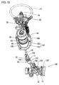
- Figure 3 is a perspective view of the steering device in the first embodiment;
- Figure 4 is a sectional view showing an actuator section of the steering device in the first embodiment;
- Figure 5 is an enlarged sectional view of the actuator section shown in Figure 4;
- Figure 6 is a cross-sectional view taken along the line A-A in Figure 5 and Figure 17;
- Figure 7 is a cross-sectional view taken along the line B-B in Figure 5 and Figure 17;
- Figure 8 is a top view of a cable case of the steering device in the first embodiment;
- Figure 9 is a bottom view of the cable case;
- Figure 10 is a cross-sectional view taken along the line C-C in Figure 5 and Figure 17;
- Figure 11 is a sectional view of the actuator section attached to a dashboard;
- Figure 12 is a sectional view of the actuator section attached to the dashboard with a rubber boot being compressively deformed;
- Figure 13 is a plan view of a prior art steering device;
- Figure 14 is a side view of a steering device in the second embodiment according to the present invention;
- Figure 15 is a perspective view of the steering device in the second embodiment;
- Figure 16 is a sectional view showing an actuator section of the steering device in the second embodiment;
- Figure 17 is an enlarged sectional view of the actuator section shown in Figure 16;
- Figure 18 is a partly sectional view of the actuator section in a partly disassembled state;
- Figure 19 is a sectional view showing the lower end portion of the actuator section in an exaggerated scale;
- Figure 20 is a sectional view of the actuator section attached to a dashboard in the second embodiment; and
- Figure 21 is a sectional view of the actuator section in the second embodiment attached to the dashboard with a rubber boot being compressively deformed.
- Hereafter, a first embodiment according to the present invention will be described with reference to Figures 1 through 12.
- Figure 1 shows a vehicle provided with a
steering device 10 according to the present invention. Asteering gear unit 69 is provided between a pair offront wheels 11, 11 (corresponding to steerable wheels in the present invention) provided on the vehicle. Thesteering gear unit 69 is of the structure that apinion 15 is meshing with arack 12 passing through acylindrical rack case 12C. Therack case 12C is fixed avehicle body 14, and therack 12 is connected at its opposite ends to the respectivefront wheels tie rods pinion 15 and asteering handle 17 are connected through asteering shaft 90, and anactuator 18 is provided at an intermediate portion of thesteering shaft 90. - Specifically, the
steering shaft 90 is composed of a first steering shaft 74 (corresponding to an upper side portion of a steering shaft in the present invention) on thesteering handle 17 side and a second steering shaft 70 (corresponding to a lower side portion of the steering shaft in the present invention) on thesteering gear unit 69 side, and theactuator 18 is connected between the first andsecond steering shafts second steering shaft 70 is provided with auniversal joint 71 at an intermediate portion thereof, and abase shaft 73A extending downward from theuniversal joint 71 is connected to thepinion 15 in axial alignment with the same, whereas aconnection sleeve 73B extending upward from theuniversal joint 71 is tiltable relative to thebase shaft 73A. - The
universal joint 71 is biforked at an upper end portion of thebase shaft 73A as well as at a lower end portion of theconnection sleeve 73B and is constructed so that afirst shaft 73C whose opposite ends are carried on thebase shaft 73A intersects perpendicularly with asecond shaft 73D whose opposite ends are carried on theconnection sleeve 73B. Thus, rotation can be transmitted between thebase shaft 73A and theconnection sleeve 73B with the rotational axes of thebase shaft 73A and theconnection sleeve 73B intersecting with each other at a certain angle. And, theconnection sleeve 73B takes a cylindrical shape and has a spline formed at an internal surface thereof. Further, at an upper end of theconnection sleeve 73B, there is provided abolt 72 for shrinking the diameter of theconnection sleeve 73B. - In Figure 2, a
numeral 75 denotes a column assy (or assembly), which is attached to an installment panel reinforcement (not shown) provided in thevehicle body 14. Thecolumn assy 75 is able to vary its angle relative to thevehicle body 14 in a vertical direction, as applied in ordinary vehicles. Thefirst steering shaft 74 is rotatably carried in thecolumn assy 75. The steering handle 17 is removably attached to a portion (refer to Figure 3) protruding from the upper end of the column assy 75 of thefirst steering shaft 74. Further, the steering handle 17 is provided with anairbag 17A. - As shown in Figures 4 and 5, the
actuator 18 is provided with a differentialtype reduction gear 20 and anelectric motor 25 for driving thereduction gear 20. A pair ofouter rings reduction gear 20. Each of theouter rings outer ring 21. Aninner ring 23 is commonly fitted in the outer rings 21, 22 and is provided at a circumferential surface thereof with plural fine teeth being able to be meshed commonly with the teeth of the bothouter rings inner ring 23 is formed to be ellipse or oval, so that a part of the teeth of theinner ring 23 is in meshing with parts of the teeth of theouter rings - The
motor 25 is arranged at an upper side of thereduction gear 20 in axial alignment with the same. Arotor 26 of themotor 25 is coupled to theinner ring 23 of thereduction gear 20 to be rotatable bodily. And, astator 28 of themotor 25 and theouter ring 21 at the upper side are fixedly fitted in anassy sleeve 19. - On the other hand, the
outer ring 22 at the lower side is allowed to rotate relative to theassy sleeve 19. Thus, when theinner ring 23 is drivingly rotated by themotor 25, theouter ring 22 at the lower side is rotated faster than theouter ring 21 at the upper side because the former is fewer by one in tooth number than the latter. That is, theouter ring 22 is rotated slightly by an angle corresponding to one tooth upon one rotation of theinner ring 23, so that the speed reduction effect can be obtained between themotor 25 and theouter ring 22. - The
outer ring 22 is coupled to an outputside connection shaft 16. Specifically, as shown in Figure 4, the outputside connection shaft 16 is composed of afirst shaft component 16A of a pipe shape and asecond shaft component 16B inserted into the lower end portion of thefirst shaft component 16A, and acoupling disc 24 is provided at the upper end portion of thefirst shaft component 16A. Thecoupling disc 24 is fixed to theouter ring 22 to be rotatable bodily therewith. - The
second shaft component 16B is provided at its upper end portion with afriction engagement portion 16C, which is urged to be pressured upon the lower end internal surface of thefirst shaft component 16A. Usually, the upper end portion of thesecond shaft component 16B is held on the lower end portion of thefirst shaft component 16A through the friction engagement between thefriction engagement portion 16C and the lower end internal surface of thefirst shaft component 16A. However, when an axis force which is greater than a predetermined value is axially applied on the outputside connection shaft 16, thesecond shaft component 16B is pushed into thefirst shaft component 16A, so that the outputside connection shaft 16 becomes short as a whole. The friction force at thefriction engagement portion 16C is adjustable by screw adjustment of asetting screw 16D provided at thefriction engagement portion 16C. - As shown in Figure 5, a
closing cap 85 is attached to a lower end opening of theassy sleeve 19. The outputside connection shaft 16 passes through the center of theclosing cap 85. Anoil seal 82 sticking firmly to the outputside connection shaft 16 is provided at the internal surface of a portion of theclosing cap 85 where the outputside connection shaft 16 passes through. - Also in Figure 5, a
position sensor 31 for detecting the rotational position of therotor 26 is provided on the upper end portion of themotor 25. Arotary shaft 26S provided at the center of therotor 26 protrudes from the upper end surface of themotor 25, and alock disc 32 is fixed to a protruding portion of therotary shaft 26S to be rotatable bodily therewith. Further, as shown in Figure 6, apillar 34 is upstanding at a position adjacent to the circumferential edge of the upper surface of themotor 25, and alock arm 33 is pivotably carried on thepillar 34. Thelock arm 33 is urged by atorsion spring 33C to be engaged with thelock disc 32 and is released from engagement with thelock disc 32 by energizing asolenoid 35 provided on the upper surface of themotor 25. Thus, when the energization of thesolenoid 35 is discontinued in the state of emergency, therotor 26 is brought into the lock state. - On the upper surface of the
motor 25, there are provided aterminal furniture 25X for windings of themotor 25 and thesolenoid 35 and aterminal furniture 25Y for theposition sensor 31. - As shown in Figure 5, the upper end portion of the
motor 25 is covered with acoupling housing 36. Thecoupling housing 36 is provided with atop plate portion 36A facing the upper surface of themotor 25, a large-diametercylindrical portion 36B extending downward from thetop plate portion 36A and a small-diametercylindrical portion 36C extending upward from thetop plate portion 36A. The lower end portion of the large-diametercylindrical portion 36B is fixedly fitted on the upper end portion of theassy sleeve 19. - As shown in Figure 6, the large-diameter
cylindrical portion 36B is partly cut away to form awork window 36W. Thework window 36W enables theterminal furniture 25X and theterminal furniture 25Y to face outside therethrough. Thework window 36W is closed by means of an insidecylindrical member 43 referred to later. - As shown in Figure 5, an input
side connection shaft 78 is fixed to the inside bottom surface of the small-diametercylindrical portion 36C. Specifically, the inputside connection shaft 78 is provided with a universal joint 79 at an intermediate portion thereof and is further composed of abase section 76 and ajoint sleeve 77 respectively at lower and upper sides of theuniversal joint 79. Thebase section 76 takes a U-letter shape, and anembossment 76E protrudes from the lower surface of a plinth provided beneath thebase section 76. Theembossment 76E is fitted in a center hole formed in the inside bottom surface of the small-diametercylindrical portion 36C to align thebase section 76 with the axis of theactuator 18. - The
universal joint 79 is provided with afirst shaft 76A whose opposite ends are carried on thebase section 76 and asecond shaft 76B rotatably carried and extending perpendicularly to thefirst shaft 76A, and the lower end portion of thejoint sleeve 77 is fixed to thesecond shaft 76B. Thus, thebase section 76 and thejoint sleeve 77 are able to rotate bodily with a bent state being held between thebase section 76 and thejoint sleeve 77. Thejoint sleeve 77 is provided with a cylindrical space, whose internal surface has spine formed thereon. Thefirst steering shaft 74 is spline-connected with thejoint sleeve 77 by being inserted thereinto. - A
cable case 39 is assembled on the upper portion of thecoupling housing 36. Thecable case 39 is constituted by fitting a case innercylindrical component 40 and a case outercylindrical component 41 to be rotatable relatively. The case innercylindrical component 40 takes a cylinder shape fixed to the small-diametercylindrical portion 36C of thecoupling housing 36 and protrudes acircular bottom wall 40A at the lower end portion thereof. Thecircular bottom wall 40A of the case innercylindrical component 40 is fixed at the lower end surface thereof to the upper end portion of the insidecylindrical member 43, and the insidecylindrical member 43 closes thework window 36W of thecoupling housing 36, as mentioned earlier. - On the other hand, the case outer
cylindrical component 41 takes a generally cylindrical shape which has a lager inner diameter than thecircular bottom wall 40A to surround the whole of the case innercylindrical component 40 and expands awire leading section 41 D radially outward at a part of the circumferential surface thereof, as shown in Figure 7. Further, an upper end opening of the case outercylindrical component 41 is closed with aring cap 42, as shown in Figure 5. Additionally, acylindrical wall 42A is suspended downward from the inner circumference of thering cap 42, and the lower end portion of thecylindrical wall 42A is loosely fitted on the inside upper end portion of the case innercylindrical component 40. - A ring-
like bottom wall 41A protrudes radially inwardly from the lower end portion of the case outercylindrical component 41 to be overlapped with thecircular bottom wall 40A, and aboot holder sleeve 41C of a generally cylindrical shape is suspended downward from the inner circumference of the ring-like bottom wall 41A. - As shown in Figure 6, a portion of the
boot holder sleeve 41C which portion corresponds to thework window 36W of thecoupling housing 36 is partly cut away to form anotherwork window 41W. Asheet metal ring 44 is fitted on the outer surface of theboot holder sleeve 41C. Thework window 41W is closed with thesheet metal ring 44. Further, as shown in Figure 5, aflange portion 41T is protruded radially outwardly from the lower end circumference of theboot holder sleeve 41C, and thesheet metal ring 44 engages at its lower end portion with theflange portion 41T. - As shown in Figure 7, a
spiral cable 45 is housed in an annular space defined between the case innercylindrical component 40 and the case outercylindrical component 41. Specifically, thespiral cable 45 is wound around a cylindrical portion of the case innercylindrical component 40 and is secured to the case innercylindrical component 40 at its inside terminal portion and to thewire leading section 41D of the case outercylindrical component 41 at its outside terminal portion. Inside thewire leading section 41D, plural electric paths provided in thespiral cable 45 are connected to anexternal cable 52, which is led outside thecable case 39. - Figure 8 is a bottom view of the
cable case 39. As shown in this figure, thecircular bottom wall 40A of the case innercylindrical component 40 of thecable case 39 is provided thereon withplural terminal furniture terminal furniture 25X for themotor 25 and theterminal furniture 25Y for theposition sensor 31. Theseterminal furniture circular bottom wall 40A of the case innercylindrical component 40 and are connected to plural electric paths provided in thespiral cable 45. As shown in Figure 9, thetop plate portion 36A of thecoupling housing 36 has acutout 36F formed for allowing theterminal furniture - When the
cable case 39 is attached to thecoupling housing 36, theterminal furniture cylindrical component 40 are brought into face-to-face relations respectively with theterminal furniture 25X for themotor 25 and theterminal furniture 25Y for theposition sensor 31. At this time, thework windows terminal furniture terminal furniture work windows work windows terminal furniture terminal furniture work windows cylindrical member 43 andsheet metal ring 44 to the respectively set positions. - A
first rubber boot 46 is attached to theboot holder sleeve 41C of the case outercylindrical component 41. Thefirst rubber boot 46 takes a cylindrical shape opened at opposite ends thereof and is fixed to the case outercylindrical component 41 in such a manner that an upper endfitting portion 46A provided at the upper end is fitted on the outer surface of thesheet metal ring 44 fitted on theboot holder sleeve 41C and that then, aclamp ring 47 is clamped on the outer surface of the upper endfitting portion 46A. The upper end portion of the upper endfitting portion 46A radially outwardly extends aflange portion 46B for ensuring that the upper endfitting portion 46A is prevented from coming out therefrom. - The
first rubber boot 46 is formed at its lower end portion with a lower endfitting portion 46C which is approximately the same in diameter as the upper endfitting portion 46A and is provided between the upper and lowerfitting portions cylindrical body portion 46D whose diameter is larger than those of thefitting portions cylindrical body portion 46D is constructed to join a pair of taper cylinders arranged in alignment vertically so that the center portion in the axial direction becomes largest in diameter. Abendable portion 46K having aridge line 46R is formed at the center portion in the axial direction of thecylindrical body portion 46D. Further, plural engagingprotrusions 46L arranged circumferentially are formed on the internal surface at a boundary portion with the lower endfitting portion 46C of thecylindrical body portion 46D. More specifically, as shown in Figure 10, the engagingprotrusions 46L are formed at six positions which equally divides the circumference of thefirst rubber boot 46. - As shown in Figure 5, a
flange portion 46E overhangs radially outwardly from the lower end circumference of the lower endfitting portion 46C. Aninner metal sleeve 48 is inserted into the internal surface of the lower endfitting portion 46C. Theinner metal sleeve 48 is prevented from coming out therefrom by engaging aflange portion 48A, which overhangs radially outwardly from the upper end portion thereof, with the inside upper circumferential edge portion of the lower endfitting portion 46C. Further, as shown in Figure 10, theflange portion 48A haspit portions 48D formed at the six positions equally dividing the circumference thereof, and thesepit portion 48D receives the engagingprotrusions 46L therein thereby to secure theinner metal sleeve 48 against rotation relative to thefirst rubber boot 46. - As shown in Figure 5, the
inner metal sleeve 48 is fitted at its upper half in the lower endfitting portion 46C and protrudes its lower half downward from the lower endfitting portion 46C. Asecond rubber boot 49 has its upper end portion fitted on the lower half of theinner metal sleeve 48 and vulcanized to be adhered thereto. Thus, the first andsecond rubber boots rubber boot 120 in the present invention. - The
second rubber boot 49 takes a cylindrical shape opened at opposite ends thereof and is provided with acylindrical body section 49A, abellows section 49B and aseal section 49C in turn from top toward bottom. An outer metal sleeve 50 (corresponding to a metal sleeve in the present invention) is fitted on the outer surface of thebody section 49A and is adhered to thebody section 49A by vulcanizing the same. Aflange portion 50A overhangs radially outwardly from the upper end portion of theouter metal sleeve 50, and aflange portion 49D overhangs radially outwardly from the upper end portion of thebody section 49A to be overlapped over theflange portion 50A. - The
bellows section 49B as a whole decreases in diameter as it goes down and takes a so-called bellows construction that pluralbendable portions 49E are provided at the intermediate portion in the axial direction. Theseal section 49C is closely fitted on the circumferential surface of the outputside connection shaft 16. However, when the outputside connection shaft 16 is rotated in connection with the steering manipulation of thesteering handle 17, theseal section 49C allows the outputside connection shaft 16 to slidden thereon. In this way, by covering the whole of theactuator 18 with thefirst rubber boot 46 and thesecond rubber boot 49 and by making theseal section 49C at the lower end portion of thesecond rubber boot 49 closely fitted on the outputside connection shaft 16 to allow the same slidably thereon, there can be attained not only a waterproof effect and a dustproof effect but also a soundproof effect against the operating noise of theactuator 18. - As shown in Figure 11, a
boot insertion bracket 101 for fixing theactuator 18 to adashboard 100 of thevehicle body 14 is fitted and attached onto the outer surface of theouter metal sleeve 50. Theboot insertion bracket 101 is made of rubber and is constructed to erect acylindrical portion 102 obliquely upward from aflat plate portion 103 which is set on the opening edge portion of a throughhole 100A formed on thedashboard 100. As shown in Figure 3, theflat plate portion 103 is fixed by means of plural bolts to thedashboard 100 at its whole circumferential portion. Further, theactuator 18 is fitted in thecylinder portion 102 at theouter metal sleeve 50 thereof and is positioned with theflange portion 50A of theouter metal sleeve 50 being seated on the upper end surface of thecylindrical portion 102. Further, aclamp ring 105 is attached to the circumferential surface of the upper end portion of thecylinder portion 102. By clamping theclamp ring 105 with theouter metal sleeve 50 placed inside thecylinder portion 102, theactuator 18 is prevented from coming out as well as from rotating. - The
steering device 10 as constructed above will be assembled to thevehicle body 14 as follows: - Before assembling the
actuator 18, thesteering gear unit 69 is fixed to a bottom portion of thevehicle body 14 in advance, and the column assy 75 is fixed to the installment panel reinforcement in advance. Also, in advance, theboot insertion bracket 101 is fixed to thedashboard 100. Thus, the first andsecond steering shafts dashboard 100 therebetween. The steering handle 17 is left released from thefirst steering shaft 74 of thecolumn assy 75. - Next, the
actuator 18 is inserted into thecylindrical portion 102 of theboot insertion bracket 101. At this time, the assembling of therubber boot 120 into theboot insertion bracket 101 can be done smoothly since theouter metal sleeve 50 fixedly attached to the outer surface of therubber boot 120 slides on the internal surface of thecylindrical portion 102. Then, the outputside connection shaft 16 protruding from the lower end of theboot insertion bracket 101 is inserted into the throughhole 100A of thedashboard 100 and is spline-connected to thesecond steering shaft 70. In this state, theclamp ring 105 is clamped on the circumferential surface of theboot insertion bracket 101 to fix therubber boot 120 of theactuator 18 to the boot insertion bracket 101 (that is, to secure theactuator 18 against rotation and coming out). Since therubber boot 120 is reinforced with theouter metal sleeve 50, therubber boot 120 and theboot insertion bracket 101 can be fixed firmly. - Subsequently, the
actuator 18 is pushed down as shown in Figure 12. More specifically, this can be done by gripping thecable case 39 and then by pushing it down. Thus, thefirst rubber boot 46 is compressively deformed by being crushed down at thebendable portion 46K, whereby theactuator 18 is moved downward relative to the first andsecond rubber boots rubber boot 120 with thebendable portion 46K as described above, therubber boot 120 is enabled to be easily deformed in the axis direction, so that it can be realized to efficiently perform the assembling work of theactuator 18 onto the steeringshaft 90. - Thereafter, the
joint sleeve 77 of the inputside connection shaft 78 and thefirst steering shaft 74 are brought to face with each other with theactuator 18 having been moved down. Then, theactuator 18 is moved upward to insert the lower end portion of thefirst steering shaft 74 into thejoint sleeve 77. Thus, thefirst steering shaft 74 is spline-connected to the inputside connection shaft 78 of theactuator 18. Then, the bolt 72 (Figure 2) provided on thesecond steering shaft 70 is screwed up to secure the outputside connection shaft 16 against coming out from thesecond steering shaft 70. - Finally, the
external cable 52 led from theactuator 18 is connected to an ECU (the abbreviation of Electronic Control Unit) 60 shown in Figure 1. Through the foregoing works, theactuator 18 is assembled to thevehicle body 14, whereby thesteering device 10 is completed. - In the vehicle incorporating the
steering device 10 as constructed above, theECU 60 drivingly controls theactuator 18 in dependence on the traveling state to alter the transmission ratio of the rotation transmitted between the first andsecond steering shafts ECU 60 stores a map (not shown) wherein various transmission ratios have been set respectively in correspondence to various vehicle speeds. Thus, theECU 60 determines a transmission ratio to be selected based on a detection result of a vehicle speed sensor 62 (refer to Figure 1) and the map. Then, theECU 60 calculates a target rotational angle for the outputside connection shaft 16 from the steering angle of the steering handle 17 detected by asteering angle sensor 61 and the determined transmission ratio. In order to make the actual rotational angle of the outputside connection shaft 16 coincide with the target rotational angle, theECU 60 applies a drive current to themotor 25 through theexternal cable 52 and thespiral cable 45 thereby to rotate therotor 26. - The map has been set to have a property that the transmission ratio becomes smaller as the vehicle speed increases. Thus, it becomes realized that the
front wheels - By the way, when the steering handle 17 is rotated, a relative rotation is made between the case outer
cylindrical component 41 fixed to the dashboard of thevehicle body 14 through therubber boot 120 and the case innercylindrical component 40 fixed to theactuator 18. This results in changing the winding state of thespiral cable 45 whose opposite ends are fixed to the case outercylindrical component 41 and the case innercylindrical component 40. On the other hand, theexternal cable 52 is held between thevehicle body 14 and the case outercylindrical component 41 in the state that it does not have the load applied due to the steering handle manipulation. In the present embodiment, since therubber boot 120 is fixedly fitted on the case outercylindrical component 41 of thecable case 39 at its upper side portion and is fixed to thedashboard 100 of thevehicle body 14 over the entire circumference thereof, the case outercylindrical component 41 can be firmly secured against rotation compared with the prior art steering device wherein the case outer cylindrical component is fixed at two portions thereof by means of the V-letter shape wire. Moreover, the problem attendant on the V-letter shape wire no longer arises even in the car models wherein the case outercylindrical component 41 is relatively far from thedashboard 100. That is, according to the present embodiment, it can be realized to secure the case outercylindrical component 41 of thecable case 39 against rotation relative to thevehicle body 14 irrespective of car models. - In the vehicle in the present embodiment, when the steering handle 17 is pushed strongly upon collision, the column assy 75 is separated from the installment panel reinforcement, and the
actuator 18 is pushed down to compressively deform the outputside connection shaft 16. Thus, the steering handle 17 together with theactuator 18 is moved to go away from the driver, so that a wide space can be secured ahead of the driver. - The present invention is not limited to the foregoing embodiment. For example, the following modifications are encompassed within the technical scope of the present invention, and besides the following modifications, the present invention can be practiced in various forms without departing from the gist thereof.
- (1) Although in the foregoing first embodiment, the
rubber boot 120 is fixed to thedashboard 100 through theboot insertion bracket 101, a flange for example may be provided to overhang from the circumferential surface of therubber boot 120 and may be fixed to the opening edge portion of the throughhole 100A formed on thedashboard 100. - (2) Although in the foregoing embodiment, the upper end portion of the
rubber boot 120 is fixed with theclamp ring 47 to the case outercylindrical component 41, adhesive may be used to secure the upper end portion of therubber boot 120 fitted on the case outercylindrical component 41. - (3) Although in the foregoing embodiment, the opening edge at the lower end portion of the
rubber boot 120 is closely fitted on the outputside connection shaft 16 of theactuator 18, an open structure may be taken between the opening edge at the lower end portion of therubber boot 120 and the outputside connection shaft 16. - Hereafter, a second embodiment according to the present invention will be described. The substantial parts of the foregoing description regarding the construction of the first embodiment are also applicable to the construction of the second embodiment. However, several parts in Figures 2 through 5, 11 and 12 showing the first embodiment are improved in the second embodiment as shown in Figures 14 through 17, 20 and 21. Therefore, the foregoing description regarding the construction of the first embodiment is equally applied to the construction of the second embodiment by reading the reference to Figures 2 through 5, 11 and 12 as that to Figures 14 through 17, 20 and 21 respectively. Hereinafter, with further reference to Figures 18 and 19 featuring the second embodiment, in addition to some of Figures 14 through 17, 20 and 21, the following description regarding the construction of the second embodiment will be addressed to those respects different from the first embodiment to avoid the repetition of the foregoing description.
- In the second embodiment, as shown in Figure 15, the
pinion 15 is rotatably carried in abearing section 12D formed at the intermediate portion of therack case 12C. Thesecond steering shaft 70 is connected to the upper end portion of thepinion 15 to extend obliquely upward. - Further, as shown in Figure 19 which in an exaggerated scale, partly shows the lower end portion of the
actuator 18 shown in Figure 17, thereduction gear 20 hasplural needles 22N interposed between theouter ring 22 at the lower side and the internal surface of theassy sleeve 19, so that theouter ring 22 is rotatable smoothly within theassy sleeve 19. - Further, also in Figure 19, the
closing cap 85 which is attached to the lower end opening of theassy sleeve 19 takes the shape that acylindrical portion 85C is protruded downward from the center of anannular disc portion 85E, and the outputside connection shaft 16 passes through the interior of thecylindrical portion 85C. As described in the foregoing first embodiment, theoil seal 82 sticking firmly to the outputside connection shaft 16 is provided at the internal surface of thecylindrical portion 85C of theclosing cap 85. A threadedportion 85A is formed at an upper portion on the outer surface of theannular disc portion 85E, and theclosing cap 85 is fixed to theassy sleeve 19 by fitting the threadedportion 85A in the internal surface of theassy sleeve 19 through screw engagement. - A
flange portion 85B extends radially outwardly from the lower portion on the outer surface of theannular disc portion 85E. Theflange portion 85B is firmly stuck to the lower end surface of theassy sleeve 19 to close the lower end opening of theassy sleeve 19. Chamfers are provided at the outer edge portion of the lower end surface of theassy sleeve 19 as well as at the outer edge portion of the upper end surface of theflange portion 85B, so that an engaginggroove 85M in the present invention is formed between theflange portion 85B and theassy sleeve 19. -
Plural support ribs 85D corresponding to a cap support portion in the present invention are formed over thedisc portion 85E and thecylindrical portion 85C. Thesupport ribs 85D are arranged at a regular interval in the circumferential direction, as shown in Figure 18. As shown also in Figure 19, the outer edge portion of eachsupport rib 85D extends over the outer edge portion of thedisc portion 85E and the lower end surface of thecylindrical portion 85C and is roundish. Therefore, the lower surface of theclosing cap 85 takes a taper shape as a whole which gradually protrudes downward as it extends from the circumferential edge portion toward the center portion. - As best shown in Figure 18, the
actuator 18 has acap 80 attached from the lower side of theclosing cap 85. Thecap 80 is a formed part made of, e.g., synthetic resin (such as PET (polyethylene terephthalate), PP (polypropylene) or the like) and is higher in elasticity than metal parts or components (i.e., theassy sleeve 19 and the closing cap 85) which constitute the lower end corner of theactuator 18. - Also shown in Figure 19, the
cap 80 takes a roundish, taper shape (so-called dome shape) as a whole which gradually protrudes downward as it extends from the circumferential edge portion toward the center portion in correspondence to the lower surface shape of theclosing cap 85 and has formed at its center portion ashaft hole 80A through which the outputside connection shaft 16 passes. The upper end portion of thecap 80 is provided with acylindrical portion 80B fitted on the outer surface of the lower end portion of theactuator 18. Thecap 80 is fixed to theactuator 18 with an engagingprotrusion 80C provided on the internal surface of thecylindrical portion 80B being engaged complementarily with the engaginggroove 85M. - Further, as shown in Figure 18, the
wire leading section 41D has acase bracket 39B (also shown in Figure 14) fixed to its outer surface for fixing thecable case 39 to thevehicle body 14. - Further, through holes of, e.g. plural number are formed at the lower edge portion of an outer cylindrical sleeve 50 (corresponding to the
outer metal sleeve 50 in the first embodiment), andprotuberances 49H (Figure 17) which protrude from the lower edge portion of thebody section 49A of a second cylindrical boot 49 (corresponding to thesecond rubber boot 49 in the first embodiment) are engaged with the through holes, whereby the entirety of thebody section 49A is fixed to be stuck firmly to the outercylindrical sleeve 50. - The
steering device 10 in the second embodiment as constructed above will be assembled to thevehicle body 14 as follows: - Before assembling the
actuator 18, thesteering gear unit 69 is fixed to a bottom portion of thevehicle body 14 in advance, and the column assy 75 is fixed to the installment panel reinforcement in advance. Thus, the first andsecond steering shafts hole 100A of thedashboard 100. The steering handle 17 is left released from thefirst steering shaft 74 of thecolumn assy 75. - Then, a bracket 101 (corresponding to the
boot insertion bracket 101 in the first embodiment) is attached to theactuator 18, and the outputside connection shaft 16 protruding from the lower end of thebracket 101 is inserted into the throughhole 100A of thedashboard 100 to be brought into spline-connection with the upper end portion of thesecond steering shafts 70. In this state, theflat plate portion 103 of thebracket 101 is fixed by means of bolts to the opening edge portion of the throughhole 100A of thedashboard 100, as shown in Figure 20. - Subsequently, the
actuator 18 is pushed down as shown in Figure 21. More specifically, this can be done by gripping thecable case 39 and then by pushing it down. Thus, thebendable portion 46K of a first cylindrical boot 46 (corresponding to thefirst rubber boot 46 in the first embodiment) is crushed down to be compressively deformed, whereby theactuator 18 is moved downward relative to first and secondcylindrical boots 46, 49 (respectively corresponding to the first andsecond rubber boots actuator 18 in the present embodiment is covered with thecap 80 which is higher in elasticity, the damage of the secondcylindrical boot 49 can be avoided even when the lower end corner portion of theactuator 18 is brought into hit on the secondcylindrical boot 49. Accordingly, it becomes unnecessary to take great care in moving theactuator 18 downward, so that the efficiency in the assembling work in the present embodiment can be improved compared with that in the prior art steering device. - Thereafter, the
joint sleeve 77 of the inputside connection shaft 78 and thefirst steering shaft 74 are brought to face with each other with theactuator 18 having been moved down. Then, theactuator 18 is moved upward to insert the lower end portion of thefirst steering shaft 74 into thejoint sleeve 77. Thus, thefirst steering shaft 74 is spline-connected to the inputside connection shaft 78 of theactuator 18. Then, thecase bracket 39B attached to thecable case 39 is fixed to thevehicle body 14 by means of bolts (not shown), and thebolt 72 provided on thesecond steering shaft 70 is screwed up to secure the outputside connection shaft 16 against coming out from thesecond steering shaft 70. - Finally, the
external cable 52 led from theactuator 18 is connected to theECU 60 shown in Figure 1. Through the foregoing works, theactuator 18 is assembled to thevehicle body 14, whereby thesteering device 10 is completed. - In the vehicle incorporating the
steering device 10 constructed as described above, theECU 60 drivingly controls theactuator 18 in dependence on the traveling state to alter the transmission ratio of the rotation transmitted between the first andsecond steering shafts ROM 63 provided in theECU 60 stores the map (not shown) wherein various transmission ratios have been set respectively in correspondence to various vehicle speeds. Thus, theECU 60 determines a transmission ratio to be selected based on a detection result of the vehicle speed sensor 62 (refer to Figure 1) and the map. Then, theECU 60 calculates a target rotational angle for the outputside connection shaft 16 from the steering angle of the steering handle 17 detected by thesteering angle sensor 61 and the determined transmission ratio. Consequently, theECU 60 applies a drive current to themotor 25 through theexternal cable 52 and thespiral cable 45 to rotate therotor 26, whereby the actual rotational angle of the outputside connection shaft 16 is controlled to coincide with the target rotational angle. - As earlier described for the first embodiment, the map has been set to have a property that the transmission ratio becomes smaller as the vehicle speed increases. Thus, it becomes realized that the
front wheels - By the way, when the vehicle comes into collision, the
airbag 17A expands upon the shock of the collision. At this time, the steering handle 17 is pushed by the drivers arms or by theairbag 17A, whereby the axis force greater than a predetermined value is momentarily applied to thesteering handle 17. Thus, the column assy 75 comes out from the installment panel reinforcement to push theactuator 18 downward. This causes the insidecylindrical member 43 and the case innercylindrical component 40 of thecable case 39 to come out from thecoupling housing 36 and theassy sleeve 19. As a result, the body portion of theactuator 18 is moved obliquely downward as it compresses the outputside connection shaft 16. - In the present second embodiment, as best shown in Figure 19, since the
cap 80 covering the lower end surface of theactuator 18 takes the taper shape and since theplural support ribs 85D provided on theactuator 18 support thecap 80 from inside, theactuator 18 is moved downward as it pushes the component (e.g., the dashboard 100) at the lower side away at thecap 80 of the taper shape. Even if thecap 80 is broken at this time, thesupport ribs 85D are able to push the component at the lower side away. Accordingly, when the vehicle comes into collision, the steering handle 17 together with theactuator 18 is moved smoothly in the direction going away from the driver, so that a wide space can be secured ahead of the driver. - As described above, according to the
steering device 10 in the present second embodiment, since the lower end corner portion of theactuator 18 is covered with thecap 80 of a high elasticity, the damage of the secondcylindrical boot 49 can be obviated even when the lower end corner portion of theactuator 18 is brought into hit on the secondcylindrical boot 49 during the assembling work. Further, thecap 80 takes the taper shape and since thesupport ribs 85D support thecap 80 from inside, thehandle 17 together with theactuator 18 is moved smoothly in the direction going away from the driver upon collision of the vehicle, so that a wide space can be secured ahead of the driver. - The present invention is not limited to the foregoing second embodiment. For example, the following modifications are encompassed within the technical scope of the present invention, and besides the following modifications, the present invention may be practiced in various forms without departing from the gist thereof.
- (1) Although the
cap 80 in the foregoing second embodiment covers not only the lower end corner portion of theactuator 18 but also an area adjacent to the center portion of the lower end surface, the cap in the present invention may be constructed to cover the lower end corner portion only of theactuator 18. - (2) Although the
cap 80 in the foregoing second embodiment takes a roundish dome shape, it may be a conical shape or a pyramid shape. - (3) Although in the foregoing second embodiment, the
plural support ribs 85D are formed on the lower end surface of theactuator 18 with intervals therebetween, the entire lower end surface of theactuator 18 may be formed to take a taper shape. - (4) Although in the foregoing second embodiment, the output
side connection shaft 16 provided on theactuator 18 is constructed to be compressively deformable for enabling theactuator 18 to be moved downward, thesecond steering shaft 70 provided on thesteering gear unit 69 may instead be constructed to be compressively deformable. - Various features and many of the attendant advantages in the foregoing embodiments will be summarized as follows:
- In the
steering device 10 in the foregoing first embodiment typically shown in Figures 5 and 11, since therubber boot 120 is fitted and fixed on the case outercylindrical component 41 at the upper side portion thereof and is fixed to thedashboard 100 of thevehicle body 14 at the lower side portion thereof, the case outercylindrical component 41 can be secured against rotation more firmly than that in the prior art steering device wherein two portions on a case outer cylindrical component are fixed with a wire of a V-letter shape. Further, the problem attendant on the wire of the V-letter shape in the prior art steering device no longer arises even in the car models wherein the case outercylindrical component 41 and thedashboard 100 are relatively far from each other. That is, according to the present invention, it can be realized to secure the case outercylindrical component 41 of thecable case 39 against rotation relative to thevehicle body 14 even in any car model. - Also in the
steering device 10 in the foregoing first embodiment typically shown in Figures 5 and 11, since theouter metal sleeve 50 fixed on the outer surface of therubber boot 120 slides on the internal surface of thecylinder portion 102 of theboot insertion bracket 101, the assembling of therubber boot 120 into theboot insertion bracket 101 can be done smoothly. Further, since therubber boot 120 is reinforced by theouter metal sleeve 50, it can be realized to firmly fix therubber boot 120 and theboot insertion bracket 101 together. - Also in the
steering device 10 in the foregoing first embodiment typically shown in Figures 5 and 12, therubber boot 120 is easily deformed at thebendable portion 46K in the axial direction when brought into hit on thedashboard 100 or theboot insertion bracket 101 in assembling theactuator 18 at the intermediate portion of the steeringshaft 80. Therefore, it can be realized to efficiently perform the assembling work of theactuator 18 to the steeringshaft 90. - In the
steering device 10 in the foregoing second embodiment typically shown in Figures 18, 19 and 21, since the lower end corner portion of theactuator 18 is covered with thecap 80 being higher in elasticity, the damage of therubber boot 49 can be obviated even when the lower end corner portion of theactuator 18 is brought into hit on therubber boot 49 during the assembling work. - Also in the
steering device 10 in the foregoing second embodiment typically shown in Figures 18, 19 and 21, since thecap 80 covering the lower end surface of theactuator 18 takes the taper shape, theactuator 18 is able to move downward to push the component at the lower side away at thecap 80 of the taper shape when pushed downward together with the steering handle 17 upon collision of the vehicle. Therefore, the steering handle 17 together with theactuator 18 is moved smoothly in the direction going away from the driver upon collision of the vehicle, so that a wide space can be secured ahead of the driver. - Also in the
steering device 10 in the foregoing second embodiment typically shown in Figures 18, 19 and 21, thecap 80 is reinforced by the cap support portion (ribs 85D) when pushing the component at the lower side away upon collision of the vehicle. Since the cap support portion takes the taper shape, the cap support portion is able to push the component at the lower side away even if thecap 80 is broken. - Also in the
steering device 10 in the foregoing second embodiment typically shown in Figures 18 and 19, the engagingprotrusion 80C and the engaginggroove 85M are engaged complimentarily by fitting thecap 80 on theactuator 18, so that thecap 80 can be fixed to theactuator 18. - Obviously, numerous further modifications and variations of the present invention are possible in light of the above teachings. It is therefore to be understood that within the scope of the appended claims, the present invention may be practiced otherwise than as specifically described herein.
- In a
steering device 10, the upper side portion of arubber boot 120 is fixedly fitted on a case outercylindrical component 41 of acable case 39, and the lower side portion of therubber boot 120 is fixed to adashboard 100 of avehicle body 14 over the entire circumference thereof. Thus, the case outercylindrical component 41 can be secured against rotation more firmly compared with a prior art steering device wherein such a case outer cylindrical component is fixed at two portions thereon by means of a wire of a V-letter shape. Further, the problem attendant on the wire of the V-letter shape in the prior art steering device no longer arises even in the car models wherein the case outercylindrical component 41 and thedashboard 100 are relatively far from each other. That is, it can be realized to secure the case outercylindrical component 41 of thecable case 39 against rotation relative to thevehicle body 14 even in any car model.
Claims (10)
- A steering device comprising:an actuator provided at an intermediate portion of a steering shaft extending downward from a steering handle to pass through a dashboard of a vehicle body for altering the transmission ratio in rotation between upper and lower portions of the steering shaft in dependence on a traveling state;a cable case of a double cylindrical structure arranged on an upper surface of the actuator;a case inner cylindrical component constituting the inside of the cable case and fixed to the actuator;a case outer cylinder component constituting the outside of the cable case and rotatable relative to the case inner cylindrical component;a spiral cable provided for supplying the actuator with electric power and housed inside the cable case with itself being wound, the spiral cable being fixed to the case inner cylindrical component at one end thereof and to the case outer cylindrical component at the other end thereof; anda cylindrical rubber boot covering the circumferential surface of the actuator; wherein:an upper side portion of the rubber boot is fitted on the case outer cylindrical component to be fixed thereto; anda lower side portion of the rubber boot is fixed to the dashboard.
- The steering device as set forth in Claim 1, wherein:a boot insertion bracket is further provided having a cylindrical portion in which the rubber boot is fitted and fixed, and a flat plate portion overhanging laterally from the cylindrical portion to be fixed to the dashboard; anda metal sleeve is fixed to a portion which is inserted into the boot insertion bracket, of the outer surface of the rubber boot.
- The steering device as set forth in Claim 1, wherein a bendable portion whose ridge line extends in the circumferential direction of the rubber boot is formed between a portion fixed to the case outer cylindrical component and another portion fixed to the dashboard, of the rubber boot.
- The steering device as set forth in Claim 2, wherein a bendable portion whose ridge line extends in the circumferential direction of the rubber boot is formed between a portion fixed to the case outer cylindrical component and another portion fixed to the dashboard, of the rubber boot.
- A steering device comprising:a first steering shaft extending downward from a steering handle;a second steering shaft extending upward from a steering gear unit provided between a pair of steerable wheels;an actuator connected between the first and second steering shafts for transmitting rotation therebetween and being capable of altering the transmission ratio of the rotation in dependence on a traveling state;an input side connection shaft provided at an upper end portion of the actuator and connected to the first steering shaft through fitting engagement to be rotatable bodily therewith;an output side connection shaft protruding from a lower end surface of the actuator and connected to the second steering shaft through fitting engagement to be rotatable bodily therewith;a rubber boot covering the circumferential surface and the lower end surface of the actuator and allowing the output side connection shaft to pass through a portion thereof covering the lower end surface, the boot having an upper end portion fixedly fitted on the actuator; anda bracket for fixing an axial intermediate portion of the rubber boot to a dashboard of a vehicle body;wherein:with the rubber boot fixed to the dashboard through the bracket and with first steering shaft carried rotationally by the vehicle body, the input side connection shaft and the first steering shaft are brought into face-to-face relation by moving the actuator downward as the rubber boot is deformed compressively and are connected to each other through fitting engagement then by moving the actuator upward, andthe steering device further comprises a cap made of a member which is higher in elasticity than another member composing a lower end corner portion of the actuator, for covering the lower end corner portion of the actuator.
- The steering device as set forth in Claim 5, wherein:the cap covers the actuator from the lower end corner portion to an area adjacent to the center portion of the lower end surface and takes a taper shape which downwardly expands gradually as it extends from its circumferential edge portion toward its center portion; andthe actuator is constructed to be moved downward upon receiving from the side of the steering handle an impact which is greater in magnitude than a predetermined value.
- The steering device as set forth in Claim 6, wherein a cap support portion of a taper shape which downwardly expands gradually as it extends its circumferential edge portion toward its center portion is provided on the lower end surface of the actuator for supporting the cap from inside.
- The steering device as set forth in Claim 5, wherein:the cap is fitted at its one end on the outer side of the lower end of the actuator; andan engaging protrusion and an engaging groove which complementarily engage with each other are provided at the fitting portions of the cap and the actuator.
- The steering device as set forth in Claim 6, wherein:the cap is fitted at its one end on the outer side of the lower end of the actuator; andan engaging protrusion and an engaging groove which complementarily engage with each other are provided at the fitting portions of the cap and the actuator.
- The steering device as set forth in Claim 7, wherein:the cap is fitted at its one end on the outer side of the lower end of the actuator; andan engaging protrusion and an engaging groove which complementarily engage with each other are provided at the fitting portions of the cap and the actuator.
Applications Claiming Priority (2)
| Application Number | Priority Date | Filing Date | Title |
|---|---|---|---|
| JP2004257252A JP4548654B2 (en) | 2004-09-03 | 2004-09-03 | Steering device |
| JP2004257849A JP4408776B2 (en) | 2004-09-06 | 2004-09-06 | Steering device |
Publications (2)
| Publication Number | Publication Date |
|---|---|
| EP1632417A1 true EP1632417A1 (en) | 2006-03-08 |
| EP1632417B1 EP1632417B1 (en) | 2007-12-19 |
Family
ID=34981676
Family Applications (1)
| Application Number | Title | Priority Date | Filing Date |
|---|---|---|---|
| EP05017533A Expired - Fee Related EP1632417B1 (en) | 2004-09-03 | 2005-08-11 | Steering device |
Country Status (3)
| Country | Link |
|---|---|
| US (1) | US7549503B2 (en) |
| EP (1) | EP1632417B1 (en) |
| DE (1) | DE602005003884T2 (en) |
Cited By (1)
| Publication number | Priority date | Publication date | Assignee | Title |
|---|---|---|---|---|
| CN102139642A (en) * | 2011-03-07 | 2011-08-03 | 重庆长安汽车股份有限公司 | Cushion for automobile instrument cover |
Families Citing this family (6)
| Publication number | Priority date | Publication date | Assignee | Title |
|---|---|---|---|---|
| DE102005057865A1 (en) * | 2005-12-02 | 2007-06-06 | Dr. Johannes Heidenhain Gmbh | positioning device |
| KR20090046489A (en) * | 2007-11-06 | 2009-05-11 | 현대자동차주식회사 | Sealing device of steering column |
| DE102011075635B4 (en) * | 2011-05-11 | 2014-05-08 | Ford Global Technologies, Llc | Device for determining the steering angle of a steering wheel and steering column module equipped therewith |
| US8888132B2 (en) * | 2012-10-09 | 2014-11-18 | GM Global Technology Operations LLC | Sealing assembly |
| CN104828188B (en) * | 2015-05-20 | 2017-03-29 | 常州爱尔威智能科技有限公司 | Electrodynamic balance car |
| JP6799306B2 (en) * | 2016-09-12 | 2020-12-16 | 株式会社ジェイテクト | Mating structure and steering device equipped with this |
Citations (8)
| Publication number | Priority date | Publication date | Assignee | Title |
|---|---|---|---|---|
| US4826466A (en) * | 1987-09-11 | 1989-05-02 | Arco Industries Corporation | Steering column boot |
| US5975609A (en) * | 1996-07-26 | 1999-11-02 | Cascade Engineering, Inc. | Sound insulating layer with integral boot |
| EP0968900A1 (en) * | 1998-02-27 | 2000-01-05 | Ford Global Technologies, Inc., A subsidiary of Ford Motor Company | Sealing device for components passing through openings in panels of vehicle bodies |
| US6056297A (en) * | 1998-04-24 | 2000-05-02 | General Motors Corporation | Intermediate shaft dash panel seal |
| DE10010722A1 (en) * | 2000-03-04 | 2001-09-06 | Opel Adam Ag | Sealing unit for a steering column passing through the separation wall of a motor vehicle comprises a rigid protective plate which is positioned in front of the rubber elastic sealing element |
| US6328315B1 (en) * | 1998-12-12 | 2001-12-11 | Daimlerchrysler Ag | Sealing arrangement |
| EP1338493A1 (en) * | 2002-02-20 | 2003-08-27 | Toyoda Koki Kabushiki Kaisha | Mechanism with variable transmission ratio |
| EP1419952A2 (en) * | 2002-11-14 | 2004-05-19 | Toyoda Koki Kabushiki Kaisha | Electric steering control device |
Family Cites Families (9)
| Publication number | Priority date | Publication date | Assignee | Title |
|---|---|---|---|---|
| JPS5569825A (en) * | 1978-11-22 | 1980-05-26 | Nissan Motor Co Ltd | Transmission controller |
| US5259775A (en) * | 1990-10-24 | 1993-11-09 | Kabushiki Kaisha Tokai Rika Denki Seisakusho | Flat cable connector |
| JPH11115779A (en) * | 1997-10-16 | 1999-04-27 | Harmonic Drive Syst Ind Co Ltd | Power assisting device for motor-driven power steering |
| US6655493B2 (en) * | 2001-04-04 | 2003-12-02 | Delphi Technologies, Inc. | Steering column with non-compliant torque sensor |
| JP2003267230A (en) * | 2002-03-13 | 2003-09-25 | Honda Motor Co Ltd | Cable type steering device |
| JP4020421B2 (en) | 2002-07-26 | 2007-12-12 | 株式会社ジェイテクト | Vehicle steering system |
| JP3780985B2 (en) * | 2002-07-26 | 2006-05-31 | トヨタ自動車株式会社 | Steering control device for vehicle |
| JP2004224308A (en) | 2003-01-27 | 2004-08-12 | Toyota Motor Corp | Steering mechanism for vehicle |
| JP4165356B2 (en) | 2003-09-24 | 2008-10-15 | トヨタ自動車株式会社 | Steering device |
-
2005
- 2005-08-11 DE DE602005003884T patent/DE602005003884T2/en active Active
- 2005-08-11 EP EP05017533A patent/EP1632417B1/en not_active Expired - Fee Related
- 2005-08-29 US US11/212,679 patent/US7549503B2/en active Active
Patent Citations (8)
| Publication number | Priority date | Publication date | Assignee | Title |
|---|---|---|---|---|
| US4826466A (en) * | 1987-09-11 | 1989-05-02 | Arco Industries Corporation | Steering column boot |
| US5975609A (en) * | 1996-07-26 | 1999-11-02 | Cascade Engineering, Inc. | Sound insulating layer with integral boot |
| EP0968900A1 (en) * | 1998-02-27 | 2000-01-05 | Ford Global Technologies, Inc., A subsidiary of Ford Motor Company | Sealing device for components passing through openings in panels of vehicle bodies |
| US6056297A (en) * | 1998-04-24 | 2000-05-02 | General Motors Corporation | Intermediate shaft dash panel seal |
| US6328315B1 (en) * | 1998-12-12 | 2001-12-11 | Daimlerchrysler Ag | Sealing arrangement |
| DE10010722A1 (en) * | 2000-03-04 | 2001-09-06 | Opel Adam Ag | Sealing unit for a steering column passing through the separation wall of a motor vehicle comprises a rigid protective plate which is positioned in front of the rubber elastic sealing element |
| EP1338493A1 (en) * | 2002-02-20 | 2003-08-27 | Toyoda Koki Kabushiki Kaisha | Mechanism with variable transmission ratio |
| EP1419952A2 (en) * | 2002-11-14 | 2004-05-19 | Toyoda Koki Kabushiki Kaisha | Electric steering control device |
Cited By (1)
| Publication number | Priority date | Publication date | Assignee | Title |
|---|---|---|---|---|
| CN102139642A (en) * | 2011-03-07 | 2011-08-03 | 重庆长安汽车股份有限公司 | Cushion for automobile instrument cover |
Also Published As
| Publication number | Publication date |
|---|---|
| US20060048995A1 (en) | 2006-03-09 |
| DE602005003884D1 (en) | 2008-01-31 |
| EP1632417B1 (en) | 2007-12-19 |
| DE602005003884T2 (en) | 2008-12-11 |
| US7549503B2 (en) | 2009-06-23 |
Similar Documents
| Publication | Publication Date | Title |
|---|---|---|
| EP1632417B1 (en) | Steering device | |
| US8904902B2 (en) | Unique motor type motor driven column apparatus | |
| EP2695793A1 (en) | Steering device | |
| US10919558B2 (en) | Steering apparatus for vehicle | |
| JP4063823B2 (en) | Device for mounting components to the steering column jacket | |
| JP5768970B2 (en) | Vehicle distance sensor | |
| US11648975B2 (en) | Steering shaft for a steering system of a motor vehicle, in particular a passenger car, and motor vehicle | |
| US11529989B2 (en) | Steering apparatus | |
| CN101767606B (en) | Electric assistant steering device and assembly thereof | |
| US11396321B2 (en) | Steering device | |
| US7921958B2 (en) | Apparatus for driving steering shaft in motor-driven power steering | |
| JP4548654B2 (en) | Steering device | |
| JP4408776B2 (en) | Steering device | |
| WO2019044222A1 (en) | Steering device | |
| EP2235403B1 (en) | Vehicle range change apparatus | |
| JP2007290550A (en) | Electric power steering device | |
| US10895097B2 (en) | Drive unit assembly for a window regulator | |
| CN110469570B (en) | Fastening structure for vehicle component | |
| JP6709184B2 (en) | Electric power steering device | |
| JP3706826B2 (en) | Cable-type steering device | |
| KR101538693B1 (en) | Air conditioning system for automotive vehicles | |
| JP2020199991A (en) | Dust cover | |
| JP7052787B2 (en) | Dust cover | |
| JP2005280564A (en) | Steering device for vehicle | |
| JP5357712B2 (en) | Airbag device |
Legal Events
| Date | Code | Title | Description |
|---|---|---|---|
| PUAI | Public reference made under article 153(3) epc to a published international application that has entered the european phase |
Free format text: ORIGINAL CODE: 0009012 |
|
| AK | Designated contracting states |
Kind code of ref document: A1 Designated state(s): AT BE BG CH CY CZ DE DK EE ES FI FR GB GR HU IE IS IT LI LT LU LV MC NL PL PT RO SE SI SK TR |
|
| AX | Request for extension of the european patent |
Extension state: AL BA HR MK YU |
|
| RAP1 | Party data changed (applicant data changed or rights of an application transferred) |
Owner name: JTEKT CORPORATION Owner name: FAVESS CO., LTD. Owner name: TOYODA KOKI KABUSHIKI KAISHA Owner name: TOYOTA JIDOSHA KABUSHIKI KAISHA |
|
| 17P | Request for examination filed |
Effective date: 20060905 |
|
| AKX | Designation fees paid |
Designated state(s): DE FR GB IT |
|
| 17Q | First examination report despatched |
Effective date: 20061023 |
|
| RAP1 | Party data changed (applicant data changed or rights of an application transferred) |
Owner name: TOYOTA JIDOSHA KABUSHIKI KAISHA Owner name: JTEKT CORPORATION |
|
| GRAP | Despatch of communication of intention to grant a patent |
Free format text: ORIGINAL CODE: EPIDOSNIGR1 |
|
| GRAC | Information related to communication of intention to grant a patent modified |
Free format text: ORIGINAL CODE: EPIDOSCIGR1 |
|
| GRAS | Grant fee paid |
Free format text: ORIGINAL CODE: EPIDOSNIGR3 |
|
| GRAA | (expected) grant |
Free format text: ORIGINAL CODE: 0009210 |
|
| AK | Designated contracting states |
Kind code of ref document: B1 Designated state(s): DE FR GB IT |
|
| REG | Reference to a national code |
Ref country code: GB Ref legal event code: FG4D |
|
| REF | Corresponds to: |
Ref document number: 602005003884 Country of ref document: DE Date of ref document: 20080131 Kind code of ref document: P |
|
| ET | Fr: translation filed | ||
| PLBE | No opposition filed within time limit |
Free format text: ORIGINAL CODE: 0009261 |
|
| STAA | Information on the status of an ep patent application or granted ep patent |
Free format text: STATUS: NO OPPOSITION FILED WITHIN TIME LIMIT |
|
| 26N | No opposition filed |
Effective date: 20080922 |
|
| PGFP | Annual fee paid to national office [announced via postgrant information from national office to epo] |
Ref country code: GB Payment date: 20110810 Year of fee payment: 7 |
|
| PGFP | Annual fee paid to national office [announced via postgrant information from national office to epo] |
Ref country code: IT Payment date: 20110822 Year of fee payment: 7 |
|
| GBPC | Gb: european patent ceased through non-payment of renewal fee |
Effective date: 20120811 |
|
| PG25 | Lapsed in a contracting state [announced via postgrant information from national office to epo] |
Ref country code: IT Free format text: LAPSE BECAUSE OF NON-PAYMENT OF DUE FEES Effective date: 20120811 |
|
| PG25 | Lapsed in a contracting state [announced via postgrant information from national office to epo] |
Ref country code: GB Free format text: LAPSE BECAUSE OF NON-PAYMENT OF DUE FEES Effective date: 20120811 |
|
| REG | Reference to a national code |
Ref country code: FR Ref legal event code: PLFP Year of fee payment: 12 |
|
| REG | Reference to a national code |
Ref country code: FR Ref legal event code: PLFP Year of fee payment: 13 |
|
| REG | Reference to a national code |
Ref country code: FR Ref legal event code: PLFP Year of fee payment: 14 |
|
| PGFP | Annual fee paid to national office [announced via postgrant information from national office to epo] |
Ref country code: FR Payment date: 20200715 Year of fee payment: 16 Ref country code: DE Payment date: 20200729 Year of fee payment: 16 |
|
| REG | Reference to a national code |
Ref country code: DE Ref legal event code: R119 Ref document number: 602005003884 Country of ref document: DE |
|
| PG25 | Lapsed in a contracting state [announced via postgrant information from national office to epo] |
Ref country code: FR Free format text: LAPSE BECAUSE OF NON-PAYMENT OF DUE FEES Effective date: 20210831 Ref country code: DE Free format text: LAPSE BECAUSE OF NON-PAYMENT OF DUE FEES Effective date: 20220301 |