EP1632264B1 - Connecteur luer male - Google Patents
Connecteur luer male Download PDFInfo
- Publication number
- EP1632264B1 EP1632264B1 EP05026688A EP05026688A EP1632264B1 EP 1632264 B1 EP1632264 B1 EP 1632264B1 EP 05026688 A EP05026688 A EP 05026688A EP 05026688 A EP05026688 A EP 05026688A EP 1632264 B1 EP1632264 B1 EP 1632264B1
- Authority
- EP
- European Patent Office
- Prior art keywords
- valve
- core
- valve core
- valve body
- fluid flow
- Prior art date
- Legal status (The legal status is an assumption and is not a legal conclusion. Google has not performed a legal analysis and makes no representation as to the accuracy of the status listed.)
- Expired - Lifetime
Links
Images


Classifications
-
- A—HUMAN NECESSITIES
- A61—MEDICAL OR VETERINARY SCIENCE; HYGIENE
- A61M—DEVICES FOR INTRODUCING MEDIA INTO, OR ONTO, THE BODY; DEVICES FOR TRANSDUCING BODY MEDIA OR FOR TAKING MEDIA FROM THE BODY; DEVICES FOR PRODUCING OR ENDING SLEEP OR STUPOR
- A61M39/00—Tubes, tube connectors, tube couplings, valves, access sites or the like, specially adapted for medical use
- A61M39/22—Valves or arrangement of valves
- A61M39/26—Valves closing automatically on disconnecting the line and opening on reconnection thereof
-
- F—MECHANICAL ENGINEERING; LIGHTING; HEATING; WEAPONS; BLASTING
- F16—ENGINEERING ELEMENTS AND UNITS; GENERAL MEASURES FOR PRODUCING AND MAINTAINING EFFECTIVE FUNCTIONING OF MACHINES OR INSTALLATIONS; THERMAL INSULATION IN GENERAL
- F16K—VALVES; TAPS; COCKS; ACTUATING-FLOATS; DEVICES FOR VENTING OR AERATING
- F16K1/00—Lift valves or globe valves, i.e. cut-off apparatus with closure members having at least a component of their opening and closing motion perpendicular to the closing faces
- F16K1/12—Lift valves or globe valves, i.e. cut-off apparatus with closure members having at least a component of their opening and closing motion perpendicular to the closing faces with streamlined valve member around which the fluid flows when the valve is opened
-
- F—MECHANICAL ENGINEERING; LIGHTING; HEATING; WEAPONS; BLASTING
- F16—ENGINEERING ELEMENTS AND UNITS; GENERAL MEASURES FOR PRODUCING AND MAINTAINING EFFECTIVE FUNCTIONING OF MACHINES OR INSTALLATIONS; THERMAL INSULATION IN GENERAL
- F16L—PIPES; JOINTS OR FITTINGS FOR PIPES; SUPPORTS FOR PIPES, CABLES OR PROTECTIVE TUBING; MEANS FOR THERMAL INSULATION IN GENERAL
- F16L29/00—Joints with fluid cut-off means
- F16L29/02—Joints with fluid cut-off means with a cut-off device in one of the two pipe ends, the cut-off device being automatically opened when the coupling is applied
-
- A—HUMAN NECESSITIES
- A61—MEDICAL OR VETERINARY SCIENCE; HYGIENE
- A61M—DEVICES FOR INTRODUCING MEDIA INTO, OR ONTO, THE BODY; DEVICES FOR TRANSDUCING BODY MEDIA OR FOR TAKING MEDIA FROM THE BODY; DEVICES FOR PRODUCING OR ENDING SLEEP OR STUPOR
- A61M39/00—Tubes, tube connectors, tube couplings, valves, access sites or the like, specially adapted for medical use
- A61M39/22—Valves or arrangement of valves
- A61M39/26—Valves closing automatically on disconnecting the line and opening on reconnection thereof
- A61M2039/261—Valves closing automatically on disconnecting the line and opening on reconnection thereof where the fluid space within the valve is increasing upon disconnection
Definitions
- This invention generally relates to valves such as luer lock valves which are used primarily in the medical field, and more specifically relates to a slidable type of valve used primarily in the medical field.
- valves presently exist for use in the medical field. Such valves provide that the valve is initially biased into a closed position, where fluid cannot flow through the valve, and one or more internal components of the valve are slidable within the valve to actuate the valve into an open position, where fluid can flow through the valve.
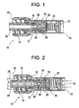
- FIGURE 1 shows the valve 10 in the closed position (wherein fluid cannot flow through the valve)
- FIGURE 2 shows the valve 10 in the open position (wherein fluid can flow through the valve).
- the valve 10 includes a valve body 12, a valve poppet 14 with luer taper (with sealing member 16 thereon), an internal resilient valve stem 18, a metal compression spring 20 and a valve plug 22, all of which are within the flow path of fluid moving through the valve (the arrows 24 shown in FIGURE 2 illustrate the fluid flow path (in one of two possible directions) through the valve 10).
- the valve stem 18 may include flutes or ribs on an external surface 26 thereof to facilitate fluid flow around the stem 18 when the valve 10 is in the open position.
- engagement or mating structure 28 such as a syringe, another valve or some other structure, engages the valve poppet 14, pushing it generally into the valve body 12 causing the valve 10 to move from the closed position as shown in FIGURE 1 to the open position as shown in FIGURE 2.
- engagement or mating structure 28 such as a syringe, another valve or some other structure, engages the valve poppet 14, pushing it generally into the valve body 12 causing the valve 10 to move from the closed position as shown in FIGURE 1 to the open position as shown in FIGURE 2.
- the valve stem 18 is disengaged from a valve seat 30 in the valve 10. This provides that fluid can ultimately flow from a bore 32 provided in the valve poppet 14 to an area 34 adjacent the periphery of the valve stem 18, or vice versa if the fluid is flowing in the opposite direction.
- valve stem 18 deflects the fluid to an area 34 adjacent the periphery of the valve stem 18, and the fluid flows along the external surface 26 of the valve stem 18 (and along the ribs, if provided, on the external surface 26 of the valve stem 18), past the valve seat 30, along the compression spring 20, and out the plug 22, and specifically between fins of the plug 22 and out the valve 10.
- fluid flows into the plug 22 of the valve 10, along the compression spring 20, past the valve seat 30, along the periphery of the valve stem 18 (and along the ribs, if provided, on the external surface 26 of the valve stem 18), to the notch 36 in the valve poppet 14 (and/or to a notch (not shown) in surface 38 of the valve stem 18), and through the bore 32 in the valve poppet 14 to the mating structure 28.
- valve 10 The overall design of the valve shown in FIGURES 1 and 2 -- being that there are so many components in the fluid flow path -- results in substantial restriction to fluid flow through the valve 10. As a result, the valve 10 cannot effectively conduct fluids having viscosities of 1.0 to 1.5 centipoise and above. Additionally, the design provides that there are numerous cavities or "dead areas" for entrapment of fluid within the valve 10. The existence of dead areas, and the fact that there so many components in the fluid flow path, creates turbulence in the fluid flow as the fluid flows through the valve 10. The turbulence renders the valve 10 a poor candidate for transmitting human blood, blood products, or any other material which is sensitive to turbulence. With regard to blood, concerns of lycing (i.e.
- FIGURES 1 and 2 provides that while the valve poppet 14 is installed through the one end 40 of the valve 10, the other components (i.e. the valve stem 18, compression spring 20, and plug 22) are installed through the other end 42. This complicates and increases the cost of the assembly process.
- a valve comprising a valve body with a sealing surface, a valve core with a central throughbore, a self-aligning valve seat member, a spring means to bias the valve closed, with the valve core slidable within the valve body for disengaging the valve seat from the sealing surface.
- a general object of an embodiment of the present invention is to provide a valve which has increased flow rate and an unobstructed fluid flow path.
- Another object of an embodiment of the present invention is to provide a valve which has fewer components within the fluid flow path.
- Still another objection of an embodiment of the present invention is to provide a valve which causes less turbulence to the fluid flow.
- Still yet another object of an embodiment of the present invention is to provide a valve which minimizes the residual volume (i.e. "dead areas") contributing to fluid entrapment.
- a valve in accordance with the present invention is defined in Claim 1, with preferred or optional features being the subject of the appended sub-claims.
- At least one end of the valve is preferably configured for a luer lock fitting.
- a bore extends through the valve core, along a longitudinal axis thereof, and the bore defines a fluid flow area.
- the one or more ports on the valve core which align with the sealing surface of the valve body when the valve is in the closed position and with the one or more slots in the valve body when the valve is in the open position consists of one or more openings in a wall of the valve core.
- the valve body also includes a fluid flow area. Hence, a fluid flow path through the valve is defined by the fluid flow area defined through the valve core (i.e. the bore and the one or more ports) and the fluid flow area of the valve body.
- the spring means is generally between the valve body and valve core, but is not within the fluid flow path through the valve.
- each slot in the valve body is larger than each respective port of the valve core, and each port of the valve core is larger than a cross-sectional diameter of the bore which extends through the valve core.
- the valve core includes two ports and the valve body includes two corresponding slots which align with each other when the valve core slides within the valve body to the open position.
- the ports of the valve core and the slots of the valve body are preferably 180 degrees apart relative to each other.
- a first sealing member and a second sealing member are disposed on the valve core, where the first sealing member engages the sealing surface of the valve body whether the valve core is in the open or the closed position, and the second sealing member engages with the sealing surface of the valve body when the valve core is in the closed position, but disengages from the sealing surface of the valve body when the valve core is in the open position.
- the valve core may include at least one barb which abuts against an internal surface of the valve body when the valve core is biased into the closed position by the spring means.
- the valve body includes a pocket
- the valve core includes a shoulder
- the spring means is disposed in the pocket of the valve body and engages the shoulder of the valve core.
- the spring means is generally between the valve body and valve core, but is not within the fluid flow path through the valve.
- a resilient material may be over-molded or co-injected on the valve core to enhance the seal with the structure which is engaged with the valve and to enhance the seal between the valve core and valve body.
- a valve in accordance with the present invention, includes a self-aligning valve seat carrier which is pivotably or adjustably engaged with a valve core member.
- the valve includes a valve body which includes a sealing surface, and the valve core is disposed in the valve body.
- the self-aligning valve seat carrier also includes a sealing surface.
- Spring means is engaged with the valve body and the valve core and it is not disposed in the fluid flow path of said valve. The spring means biases the valve core into a closed position wherein the sealing surface of the self-aligning valve seat carrier engages the sealing surface of the valve body thereby prohibiting fluid flow through the valve.
- the valve core is slidable within the valve body such that the valve is actuated to an open position wherein the sealing surface of the self-aligning valve seat carrier disengages from the sealing surface of the valve body thereby allowing fluid flow through the valve.
- the self-aligning valve seat carrier may take several different configurations.
- the self-aligning valve seat carrier may include a pair of arms which engage corresponding recessed grooves proximate the end of the valve core, may include a ball which engages a corresponding socket on the valve core, or may include a barb which engages corresponding structure on an end of the valve core.
- a sealing member may be disposed on the valve seat carrier, or a sealing material may be co-injected or over-molded onto the exterior surface thereof.
- a valve 100a of Patent Application EP-A-1 434 620 is shown in FIGURES 3-5, and a valve 100b is shown in FIGURE 6.
- a valve 100c which is in accordance with the present invention is shown in FIGURE 7
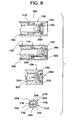
- a valve 100d which is in accordance with another embodiment of the present invention is shown in FIGURE 8
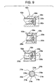
- a valve 100e which is in accordance with yet another embodiment of the present invention is shown in FIGURE 9.
- each of the valves shown in FIGURES 3-9 provides that fewer components are within the fluid flow path. As a result, each valve provides increased flow rate, a relatively unobstructed fluid flow path, and less turbulent fluid flow. Additionally, each valve minimizes the residual volume (i.e. "dead areas") contributing to fluid entrapment, and each provides enhanced backpressure tolerance when the valve is in the closed position. Additionally, the valves are inexpensive and easy to manufacture. Specifically, the valves shown in FIGURES 3-6 provide that assembly can be performed solely through one end of the valve body, as opposed to some components having to be installed through one end of the valve body and other components of the valve having to be installed through the other end of the valve body during the assembly process.
- the valve 100a shown in FIGURES 3-5 will be described first and then the differences between the other valves 100b-100e and the valve 100a shown in FIGURES 3-5 will be described.
- the valve 100a shown in FIGURES 3-5 includes a valve core 102a, a pair of sealing members 104a, 106a which are disposed on the valve core 102a, a valve body 108a, and spring means 110a which is disposed in the valve body 108a, generally between the valve core 102a and the valve body 108a.
- the valve core 102a and valve body 108a are preferably made of plastic, while the sealing members 104a, 106a are preferably made of rubber or silicone, and the spring means 110a is preferably made of metal.
- valve body 108a is a generally hollow, cylindrical component having a central throughbore 112a.
- the valve body 108a may be made of, for example, clear plastic.
- the valve body 108a has a distal end 114a as well as a proximal end 116a which is generally opposite the distal end 114a.
- both the valve core 102a (including the sealing members 104a, 106a which are disposed thereon) and the spring means 110a are installed through the distal end 114a of the valve body 108a to assemble the valve 100a.
- the distal end 114a of the valve body is preferably configured for a male luer fitting.
- the valve body 108a preferably includes threading 118a at the distal end 114a for engagement with corresponding mating structure 120 (see FIGURE 4), such as a syringe, another valve, or some other structure, in a luer lock arrangement.
- the valve body 108a includes a main body wall 122a which effectively defines the external surface of the valve 100a, and internal walls 124a which are connected to the main body wall 122a. As will be described more fully later herein, the internal walls 124a define sealing surfaces 126a which cooperate with ports 130a on the valve core 102a to prevent fluid flow through the valve 100a.
- the internal walls 124a of the valve body 108a and the main body wall 122a of the valve body 108a define a pocket 132a, and the spring means 110a is disposed in the pocket 132a.
- the spring means 110a is preferably a metal compression spring which has one end disposed in the pocket 132a in the valve body 108a and has an opposite end contactably engaged with a shoulder 134a on the valve core 102a.
- the end 135a of the valve core 102a preferably includes barbs 136a, or some other suitable structure, for generally retaining the valve core 102a in the valve body 108a, and preventing the valve core 102a from being pushed completely out of the valve body 108a by the compression spring 110a (via contactable engagement with internal surface 138a of the valve body 108a -- see FIGURE 3). Additionally, the barbs 136a provide that the valve core 102a can be snapped into the valve body 108a through the distal end 114a during assembly (see FIGURE 5).
- the valve core 102a is a generally hollow, cylindrical member having a central throughbore 140a.
- the central throughbore 140a extends along a longitudinal axis 142a of the valve core 102a and defines a fluid flow area.
- the valve core 102a includes a forward portion 144a, middle portion 146a which provides shoulder 134a, and a rearward portion 148a.
- the forward portion 144a of the valve core 102a preferably has a male luer taper to facilitate the luer lock engagement with the corresponding mating structure.
- the forward portion 144a of the valve core 102a has a standard ANSI/ISO luer configuration.
- the middle portion 146a of the valve core 102a (which provides shoulder 134a) contactably engages an internal surface 150a of the valve body 108a and is disposed between the forward (144a) and rearward (148a) portions of the valve core 102a.
- the structure 120 pushably engages the middle portion 146a of the valve core 102a causing the valve core 102a to translate or slide relative to the valve body 108a which causes the compression spring 110a to compress and the valve 100a to actuate into the open position as shown in FIGURE 4.
- the valve core 102a includes a pair of ports 130a on the rearward portion 148a of the valve core 102a.
- the ports 130a are effectively openings through the surface of the valve core 102a, in communication with the central throughbore 140a (and the fluid flow area defined thereby).
- the ports 130a on the valve core 102a are 180 degrees apart relative to each other along the external circumferential surface of the rearward portion 148a of the valve core 102a.
- the valve 100a shown in FIGURES 3-5 provides that there are a pair of sealing members 104a, 106a disposed on the valve core 102a proximate the ports 130a on the valve core 102a.
- the sealing members 104a, 106a may comprise o-rings. Specifically, one sealing member 104a is disposed on the valve core 102a between the ports 130a and the middle portion 146a of the valve core 102a, and another sealing member 106a is disposed on the valve core 102a between the ports 130a and the end 135a of the valve core 102a.
- glands 151a are preferably provided on the external surface of the valve core 102a for seating the sealing members 104a, 106a on the valve core 102a.
- the valve 100a is configured such that the one sealing member 104a always remains engaged with the sealing surfaces 126a in the valve 100a which are provided by the internal walls 124a of the valve body 108a regardless of whether the valve 100a is in the closed (see FIGURE 3) or open (see FIGURE 4) position. Sealing member 104a prevents fluid from leaking into the area in which the spring 110a is located, and does so regardless of whether the valve 100a is in the closed (see FIGURE 3) or open (see FIGURE 4) position.
- the valve 100a is configured such that the other sealing member 106a is engaged with the sealing surfaces 126a when the valve 100a is in the closed position (see FIGURE 3), but becomes disengaged therefrom when the valve 100a is actuated into the open position (see FIGURE 4). Hence, the sealing member 106a prevents fluid communication between the valve ports 130a and a fluid flow area 152a of the valve body 108a when the valve 100a is in the closed (see FIGURE 3) position.
- valve 100a is configured such that the ports 130a on the valve core 102a align with the sealing surfaces 126a in the valve 100a when the valve 100a is in the closed position (see FIGURE 3), but move out of alignment with the sealing surfaces 126a when the valve 100a is actuated into the open position (see FIGURE 4).
- the valve body 108a includes internal slots 154a which correspond with the ports 130a in the valve core 102a, and fluid flow area 152a of the valve body 108a is adjacent the slots 154a.
- each of the slots 154a in the valve body 108a is larger than each of the respective ports 130a of the valve core 102a, and each of the ports 130a of the valve core 102a is larger than a cross-sectional diameter 156a of the central throughbore 140a which extends through the valve core 102a. This limits the fluid flow only to that permitted by the inside diameter 156a of the standard ANSI/ISO luer configuration, which comprises the distal end 114a of the valve core 102a.
- the valve core 102a also includes a seal surface 160a on its rearward portion 148a which effectively seals off the slots 154a on the valve body 108a when the valve 100a is in the closed position as shown in FIGURE 3.
- the ports 130a of the valve core 102a move out of alignment with the sealing surfaces 126a of the valve 100a and into alignment with the corresponding slots 154a in the valve body 108a, thereby defining a fluid flow path through the valve 100a (one possible fluid flow direction is represented by arrows 162a shown in FIGURE 4).
- the fluid flow path is: into the throughbore 140a in the valve core 102a, through the ports 130a in the valve core 102a, through the corresponding slots 154a in the valve body 108a, into the fluid flow area 152a of the valve body 108a and out the end 162a of the valve 100a.
- the fluid flow path is: into the end 162a of the valve 100a, through the slots 154a in the valve body 108a, through the ports 130a in the valve core 102a, and along (and out) the throughbore 140a in the valve core 102a.
- valve 100a Before mating structure 120, such as a syringe, another valve, or some other structure is engaged with the valve 100a, the valve 100a is in the closed position as shown in FIGURE 3.
- the valve core 102a In the closed position, the valve core 102a is biased into the closed position by the spring means 110a, the ports 130a in the valve core 102a are aligned with the sealing surfaces 126a in the valve body 108a, and both sealing members 104a, 106a on the valve core 102a sealingly engage the sealing surfaces 126a, thereby preventing fluid flow between the central throughbore 140a in the valve core 102a and the fluid flow area 152a in the valve body 108a.
- valve core 102a When mating structure 120 engages the valve 100a, the mating structure 120 pushes the valve core 102a into the valve body 108a, causing the valve 100a to be actuated into the open position as shown in FIGURE 4.
- the spring 110a In the open position, the spring 110a is compressed, the ports 130a in the valve core 102a are aligned with the corresponding slots 154a in the valve body 108a, and only sealing member 104a on the valve core 102a remains sealingly engaged with the sealing surfaces 126a.
- fluid flow is permitted between the central throughbore 140a in the valve core 102a and the fluid flow area 152a in the valve body 108a.
- the valve 100b shown in FIGURE 6 is very similar to that shown in FIGURES 3-5, and includes a valve core 102b, a valve body 108b and a spring means 110b very much like the valve 100a shown in FIGURES 3-5.
- the valve 100b shown in FIGURE 6 provides that a sealing material 104b is co-injected or over-molded onto the exterior surface of the valve core 102b, on the forward 144b and rearward 148b portions.
- the sealing material 104b which is on the rearward portion 148b of the valve core 100b performs the same function as the sealing members 104a, 106a shown in FIGURES 3-5.
- the sealing material 104b which is on the forward portion 144b of the valve core 102b works to provide a seal between the mating structure 120 and the valve core 102b.
- the sealing material 104b which is co-injected or over-molded onto the exterior surface of the valve core 102b may consist of a rigid substrate material with a different resilient outer surface material shell.
- valves 100c, 100d, 100e in accordance with the invention shown in FIGURES 7-9 are similar to those shown in FIGURES 3-6 in accordance with Patent Application EP-A-1 434 620 , and each includes a valve core 102c, 102d, 102e, valve body 108c, 108d, 108e and spring means 110c, 110d (valve 100e also includes spring means much like the other valves 100a-100d, but the spring means is not specifically shown).
- each of the valves 100c, 100d, 100e shown in FIGURES 7-9 includes a self-aligning valve seat carrier 200c, 200d, 200e which is pivotably engaged (see the bottom-most cross-sectional view of FIGURES 7-9) with the valve core 102c, 102d, 102e.
- the valve body 108c, 108d, 108e of each of the valves 100c, 100d, 100e includes a sealing surface 126c, 126d, 126e which, as shown in FIGURES 7-9, may consist of an inclined surface which is inside the valve body 108c, 108d, 108e.
- the self-aligning valve seat carrier 200c, 200d, 200e also includes a sealing surface 202c, 202d, 202e provided by, for example, a sealing member which is disposed thereon.
- the spring means 110c, 110d of each valve is engaged with the valve body 108c, 108d, 108e and the valve core 102c, 102d, 102e, and the spring means 110c, 110d biases the valve core 102c, 102d, 102e into a closed position (see the top-most cross-sectional view of each of FIGURES 7-9) wherein the sealing surface 202c, 202d, 202e of the self-aligning valve seat carrier 200c, 200d, 200e engages the sealing surface 126c, 126d, 126e of the valve body 108c, 108d, 108e, thereby prohibiting fluid flow through the valve 100c, 100d, 100e.
- valve core 102c, 102d, 102e slides within the valve body 108c, 108d, 108e such that the valve 100c, 100d, 100e is actuated to an open position (see the middle cross-sectional view of each of FIGURES 7-9) wherein the sealing surface 202c, 202d, 202e on the self-aligning valve seat carrier 200c, 200d, 200e disengages from the sealing surface 126c, 126d, 126e of the valve body 108c, 108d, 108e thereby allowing fluid flow through the valve 100c, 100d, 100e (as represented by arrows 206c, 206d, 206e).
- the self-aligning valve seat carrier 200c preferably includes a hollow portion 210c that terminates in one or more openings 212c that allows fluid to flow through the valve seat carrier 200c.
- the bottom 214d, 214e of the valve core 102d, 102e provides openings 216d, 216e which allow fluid flow between fingers 218d, 218e.
- the self-aligning valve seat carrier may take several different configurations.
- the self-aligning valve seat carrier 200c includes a pair of arms 220c which engage corresponding recessed grooves 222c proximate the bottom 214c of the valve core 102c.
- the sealing member 202c which is disposed on the valve seat carrier 200c may consist of an o-ring.
- a sealing material may be co-injected or over-molded onto the exterior surface of the valve seat carrier.
- the self-aligning valve seat carrier 200d includes a ball 230d which engages a corresponding socket 232d on the valve core 102d, wherein the socket 232d is provided via the four fingers 218d which are at the bottom 214d of the valve core 102d (see the bottom-most view of FIGURE 8).
- the self-aligning valve seat carrier 200e includes a barb 230e which engages corresponding structure 232e on the end 214e of the valve core 102e, wherein the corresponding structure 232e is provided via the four fingers 218e which are at the bottom 214e of the valve core 102e (see the bottom-most view of FIGURE 9).
- the sealing member 202d, 202e which is disposed on each of the valve seat carriers 200d, 200e shown in FIGURES 8 and 9 may consist of an attached resilient seal material, wherein an additional seal is preferably provided at the valve carrier 200d, 200e/valve body 108d, 108d interface.
- a sealing material may be co-injected or over-molded onto the exterior surface of the valve seat carrier 200d,200e in each of the valves 100d, 100e shown in FIGURES 8 and 9.
- each valve seat carrier 200c, 200d, 200e is pivotable and self-aligning provides that each valve seat carrier 200c, 200d, 200e can articulate (as shown in the bottom-most cross-sectional view of each of FIGURES 7-9), and an enhanced seal is achieved between the sealing surface 126c, 126d, 126e of the valve body 108c, 108d, 108e and the valve seat carrier 200c, 200d, 200e when the valve 100c, 100d, 100e is in the closed position (the top-most cross-sectional view of each of FIGURES 7-9).
- each of the valve cores 102d, 102e of valves 100d, 100e includes fingers 218d, 218e which engage the valve seat carrier 200d, 200e.
- the valve seat carrier 200d includes a ball 230d which is received in a corresponding socket 232d in the end 214d of the valve core 102d, in the closed position (the top view of FIGURE 8)
- the fingers 218d of the valve core 102d are prevented from outward deflection by the valve body 108d.
- Each of the valves 100a-100e shown in FIGURES 3-9 provides that fewer components are within the fluid flow path, that flow rate is increased (when the valve is open), that there is a relatively unobstructed fluid flow path, and that there is less turbulence introduced into the flow. Additionally, each valve minimizes dead areas which can contribute to fluid entrapment, and each provides enhanced backpressure tolerance when the valve is in the closed position. Additionally, the valves are inexpensive and easy to manufacture.
- valves 100a and 100b provide that assembly can be performed solely through one end (i.e. end 114a shown in FIGURE 5) of the valve body 108a, 108b, as opposed to some components having to be installed through one end of the valve body and other components of the valve having to be installed through the other end of the valve body during the assembly process.
Landscapes
- Engineering & Computer Science (AREA)
- General Engineering & Computer Science (AREA)
- Health & Medical Sciences (AREA)
- Heart & Thoracic Surgery (AREA)
- Mechanical Engineering (AREA)
- Physics & Mathematics (AREA)
- Life Sciences & Earth Sciences (AREA)
- Animal Behavior & Ethology (AREA)
- General Health & Medical Sciences (AREA)
- Public Health (AREA)
- Veterinary Medicine (AREA)
- Biomedical Technology (AREA)
- Fluid Mechanics (AREA)
- Anesthesiology (AREA)
- Pulmonology (AREA)
- Hematology (AREA)
- Infusion, Injection, And Reservoir Apparatuses (AREA)
- Quick-Acting Or Multi-Walled Pipe Joints (AREA)
- Taps Or Cocks (AREA)
- Check Valves (AREA)
- Lift Valve (AREA)
- Superconductors And Manufacturing Methods Therefor (AREA)
- Multiple-Way Valves (AREA)
- Solid-Sorbent Or Filter-Aiding Compositions (AREA)
- Diaphragms For Electromechanical Transducers (AREA)
- Gyroscopes (AREA)
Claims (5)
- Connecteur traversé par un trajet d'écoulement de fluide et comprenant un corps de connecteur (108c) comprenant une surface étanche (126c) ; un boisseau (102c) disposé dans le corps de connecteur (108c) ; un siège à auto-alignement (200c) monté pivotant avec le boisseau (102c), le siège à auto-alignement (200c) comprenant une surface étanche (202c) et des moyens élastiques (110c) coopérant avec le corps de connecteur (108c) et le boisseau, les moyens élastiques (110c) poussant le boisseau (102c) dans une position fermée dans laquelle la surface étanche (202c) du siège à auto-alignement (200c) coopère avec la surface étanche (126c) du corps de connecteur (108c), empêchant ainsi l'écoulement de fluide à travers le connecteur, le boisseau (102c) étant susceptible de globalement coulisser à l'intérieur du corps de connecteur (108c) pour passer dans une position ouverte dans laquelle la surface étanche (202c) du siège à auto-alignement (200c) se dégage de la surface étanche (126c) du corps de connecteur (108c), permettant ainsi l'écoulement de fluide à travers le connecteur, caractérisé en ce que les moyens élastiques (110c) ne sont pas disposés dans le trajet d'écoulement de fluide du connecteur.
- Connecteur selon la revendication 1, dans lequel le siège à auto-alignement comprend une partie creuse qui permet l'écoulement de fluide à travers le siège à auto-alignement.
- Connecteur selon la revendication 1 ou la revendication 2, dans lequel le siège à auto-alignement comprend un ardillon qui coopère avec le boisseau.
- Connecteur selon l'une quelconque des revendications précédentes, dans lequel le siège à auto-alignement comprend une bille qui coopère avec une douille correspondante présente sur le boisseau.
- Connecteur selon l'une quelconque des revendications précédentes, dans lequel le corps de connecteur comprend une deuxième surface étanche ; le boisseau présente un perçage central qui définit une zone d'écoulement de fluide à travers le boisseau ; un élément d'étanchéité disposé sur le boisseau et coopérant avec la première surface d'étanchéité du corps de connecteur; la surface d'étanchéité étant constituée par un élément d'étanchéité disposé sur le siège à auto-alignement ; les moyens élastiques poussant le boisseau dans une position fermée dans laquelle l'élément d'étanchéité du siège à auto-alignement coopère avec la deuxième surface étanche du corps de connecteur, empêchant ainsi l'écoulement de fluide à travers le connecteur, le boisseau étant susceptible de globalement coulisser à l'intérieur du corps de connecteur pour passer dans une position ouverte dans laquelle l'élément d'étanchéité présent sur le siège à auto-alignement se dégage de la deuxième surface étanche du corps de connecteur, permettant ainsi l'écoulement de fluide à travers le connecteur.
Applications Claiming Priority (2)
| Application Number | Priority Date | Filing Date | Title |
|---|---|---|---|
| US32781701P | 2001-10-09 | 2001-10-09 | |
| EP02800872A EP1434620B1 (fr) | 2001-10-09 | 2002-10-01 | Soupape male luer |
Related Parent Applications (1)
| Application Number | Title | Priority Date | Filing Date |
|---|---|---|---|
| EP02800872A Division EP1434620B1 (fr) | 2001-10-09 | 2002-10-01 | Soupape male luer |
Publications (3)
| Publication Number | Publication Date |
|---|---|
| EP1632264A2 EP1632264A2 (fr) | 2006-03-08 |
| EP1632264A3 EP1632264A3 (fr) | 2006-03-15 |
| EP1632264B1 true EP1632264B1 (fr) | 2008-01-23 |
Family
ID=23278192
Family Applications (2)
| Application Number | Title | Priority Date | Filing Date |
|---|---|---|---|
| EP05026688A Expired - Lifetime EP1632264B1 (fr) | 2001-10-09 | 2002-10-01 | Connecteur luer male |
| EP02800872A Expired - Lifetime EP1434620B1 (fr) | 2001-10-09 | 2002-10-01 | Soupape male luer |
Family Applications After (1)
| Application Number | Title | Priority Date | Filing Date |
|---|---|---|---|
| EP02800872A Expired - Lifetime EP1434620B1 (fr) | 2001-10-09 | 2002-10-01 | Soupape male luer |
Country Status (7)
| Country | Link |
|---|---|
| EP (2) | EP1632264B1 (fr) |
| AT (2) | ATE363316T1 (fr) |
| CA (1) | CA2458531C (fr) |
| DE (2) | DE60224855T2 (fr) |
| ES (2) | ES2297597T3 (fr) |
| MX (1) | MXPA04003218A (fr) |
| WO (1) | WO2003030986A1 (fr) |
Cited By (1)
| Publication number | Priority date | Publication date | Assignee | Title |
|---|---|---|---|---|
| US8757590B2 (en) | 2009-03-22 | 2014-06-24 | Elcam Medical Agricultural Cooperative Association Ltd. | Closed male luer connector |
Families Citing this family (6)
| Publication number | Priority date | Publication date | Assignee | Title |
|---|---|---|---|---|
| ITMI20020819A1 (it) | 2002-04-18 | 2003-10-20 | Gambro Lundia Ab | Elemento di connessione e dispositivo di collegamento per tubazioni ad uso medicale |
| ES2245881B1 (es) * | 2004-06-09 | 2007-09-16 | Joan Conejero Sugrañes | Valvula para regular automaticamente el vaciado vesical en enfermos sondados. |
| JP4802914B2 (ja) * | 2006-07-28 | 2011-10-26 | 株式会社ジェイ・エム・エス | 医療用管継手及びこれを用いた輸液または血液の搬送に供されるライン |
| US9180260B2 (en) | 2013-08-30 | 2015-11-10 | Covidien Lp | Systems and methods for monitoring an injection procedure |
| WO2016164643A1 (fr) | 2015-04-07 | 2016-10-13 | Nxstage Medical, Inc. | Dispositifs, procédés et systèmes d'amorçage de dispositif de traitement sangion |
| ITUA20163611A1 (it) * | 2016-05-19 | 2017-11-19 | Borla Ind | Connettore valvolare per linee medicali |
Family Cites Families (18)
| Publication number | Priority date | Publication date | Assignee | Title |
|---|---|---|---|---|
| US1939128A (en) * | 1929-03-25 | 1933-12-12 | F C Muren | Pump valve |
| US2503495A (en) * | 1947-03-03 | 1950-04-11 | Frederick A Koester | Coupling |
| US3199831A (en) * | 1962-11-28 | 1965-08-10 | Western Brass Works | Valve |
| US3396743A (en) * | 1965-12-16 | 1968-08-13 | Halkey Roberts Corp | Oral inflation valve |
| US4089504A (en) * | 1976-12-06 | 1978-05-16 | Giuliani Robert L | Valve construction |
| US4378028A (en) * | 1981-04-13 | 1983-03-29 | Swagelok Company | Quick connect coupling |
| US4436125A (en) * | 1982-03-17 | 1984-03-13 | Colder Products Company | Quick connect coupling |
| US4957483A (en) * | 1988-10-21 | 1990-09-18 | Den-Tal-Ez, Inc. | Sterilizable syringe |
| US5184652A (en) * | 1991-07-02 | 1993-02-09 | Fan Chin Fu | Universal medication port |
| US5135025A (en) * | 1991-07-03 | 1992-08-04 | Mackal Glenn H | Articulated oral inflation valve |
| US5277402A (en) * | 1991-10-08 | 1994-01-11 | Itt Corporation | Quick connect fluid coupling with check valve |
| US5242393A (en) * | 1992-06-18 | 1993-09-07 | Becton, Dickinson And Company | Valved blunt cannula injection site |
| US5429155A (en) * | 1993-05-19 | 1995-07-04 | Moog Inc. | Cryogenic fluid coupling |
| ATA164293A (de) * | 1993-08-17 | 1995-09-15 | Dieringer Franz A | Kupplung für die verbindung von schlauchleitungen |
| IT1285266B1 (it) * | 1996-02-26 | 1998-06-03 | Borla Ind | Connettore con valvola di protezione per linee medicali di infusione/ trasfusione e simili. |
| US5776113A (en) * | 1996-03-29 | 1998-07-07 | Becton Dickinson And Company | Valved PRN adapter for medical access devices |
| US6228069B1 (en) * | 1999-04-05 | 2001-05-08 | Filtertek Inc. | Needleless access device |
| FR2802432B1 (fr) * | 1999-12-16 | 2002-03-08 | Vygon | Connecteur a obturation automatique pour raccorder une tete d'injection de liquide a une sortie d'injection |
-
2002
- 2002-10-01 AT AT02800872T patent/ATE363316T1/de not_active IP Right Cessation
- 2002-10-01 EP EP05026688A patent/EP1632264B1/fr not_active Expired - Lifetime
- 2002-10-01 DE DE60224855T patent/DE60224855T2/de not_active Expired - Lifetime
- 2002-10-01 MX MXPA04003218A patent/MXPA04003218A/es active IP Right Grant
- 2002-10-01 WO PCT/US2002/031346 patent/WO2003030986A1/fr active IP Right Grant
- 2002-10-01 ES ES05026688T patent/ES2297597T3/es not_active Expired - Lifetime
- 2002-10-01 DE DE60220427T patent/DE60220427T2/de not_active Expired - Lifetime
- 2002-10-01 AT AT05026688T patent/ATE384550T1/de not_active IP Right Cessation
- 2002-10-01 CA CA 2458531 patent/CA2458531C/fr not_active Expired - Lifetime
- 2002-10-01 ES ES02800872T patent/ES2287357T3/es not_active Expired - Lifetime
- 2002-10-01 EP EP02800872A patent/EP1434620B1/fr not_active Expired - Lifetime
Cited By (2)
| Publication number | Priority date | Publication date | Assignee | Title |
|---|---|---|---|---|
| US8757590B2 (en) | 2009-03-22 | 2014-06-24 | Elcam Medical Agricultural Cooperative Association Ltd. | Closed male luer connector |
| US10112039B2 (en) | 2009-03-22 | 2018-10-30 | Elcam Medical Agricultural Cooperative Association Ltd. | Closed male luer connector |
Also Published As
| Publication number | Publication date |
|---|---|
| WO2003030986A1 (fr) | 2003-04-17 |
| EP1632264A2 (fr) | 2006-03-08 |
| EP1632264A3 (fr) | 2006-03-15 |
| MXPA04003218A (es) | 2004-07-23 |
| EP1434620A1 (fr) | 2004-07-07 |
| DE60224855D1 (de) | 2008-03-13 |
| WO2003030986B1 (fr) | 2003-07-10 |
| ES2297597T3 (es) | 2008-05-01 |
| DE60220427D1 (de) | 2007-07-12 |
| ES2287357T3 (es) | 2007-12-16 |
| EP1434620A4 (fr) | 2005-04-13 |
| CA2458531C (fr) | 2008-08-05 |
| DE60220427T2 (de) | 2008-01-31 |
| CA2458531A1 (fr) | 2003-04-17 |
| DE60224855T2 (de) | 2008-04-30 |
| ATE363316T1 (de) | 2007-06-15 |
| EP1434620B1 (fr) | 2007-05-30 |
| ATE384550T1 (de) | 2008-02-15 |
Similar Documents
| Publication | Publication Date | Title |
|---|---|---|
| US6543745B1 (en) | Male luer valve | |
| US7160272B1 (en) | Y-site medical valve | |
| CA2591320C (fr) | Raccord luer male auto-etanche avec joints multiples | |
| US6364869B1 (en) | Medical connector with swabbable stopper | |
| US5569235A (en) | Valve and valved container for use with a syringe fitting | |
| US5228646A (en) | Latching trumpet valve for medical infusions | |
| CA2552084C (fr) | Systeme de valve d'orifice d'injection sans aiguille nettoyable a deplacement fluidique neutre | |
| CN101189466B (zh) | 带阀门的流体连接器 | |
| EP2331191B1 (fr) | Dispositif luer mâle clos destiné à minimiser les fuites lors d'une connexion et d'une déconnexion | |
| US6364861B1 (en) | Multi-valve injection/aspiration manifold | |
| PL394320A1 (pl) | Samouszczelniający łącznik medyczny typu Luer do przetaczania płynów | |
| US20040172006A1 (en) | Needleless Luer activated medical connector | |
| US20030141477A1 (en) | Slit-type swabbable valve | |
| CN114288545A (zh) | 自闭合的袋连接器 | |
| JP2004536671A5 (fr) | ||
| CA2131159A1 (fr) | Valve a usage medical | |
| EP1189653B1 (fr) | Raccord médical | |
| EP1632264B1 (fr) | Connecteur luer male | |
| US20090204078A1 (en) | Manifold and Valve Seal for Use with a Medical Device | |
| CN219062543U (zh) | 一种透析浓缩液集中供液系统的单向球阀结构 |
Legal Events
| Date | Code | Title | Description |
|---|---|---|---|
| PUAI | Public reference made under article 153(3) epc to a published international application that has entered the european phase |
Free format text: ORIGINAL CODE: 0009012 |
|
| PUAL | Search report despatched |
Free format text: ORIGINAL CODE: 0009013 |
|
| 17P | Request for examination filed |
Effective date: 20051207 |
|
| AC | Divisional application: reference to earlier application |
Ref document number: 1434620 Country of ref document: EP Kind code of ref document: P |
|
| AK | Designated contracting states |
Kind code of ref document: A2 Designated state(s): AT BE BG CH CY CZ DE DK EE ES FI FR GB GR IE IT LI LU MC NL PT SE SK TR |
|
| AK | Designated contracting states |
Kind code of ref document: A3 Designated state(s): AT BE BG CH CY CZ DE DK EE ES FI FR GB GR IE IT LI LU MC NL PT SE SK TR |
|
| AKX | Designation fees paid |
Designated state(s): AT BE BG CH CY CZ DE DK EE ES FI FR GB GR IE IT LI LU MC NL PT SE SK TR |
|
| GRAP | Despatch of communication of intention to grant a patent |
Free format text: ORIGINAL CODE: EPIDOSNIGR1 |
|
| GRAS | Grant fee paid |
Free format text: ORIGINAL CODE: EPIDOSNIGR3 |
|
| GRAA | (expected) grant |
Free format text: ORIGINAL CODE: 0009210 |
|
| AC | Divisional application: reference to earlier application |
Ref document number: 1434620 Country of ref document: EP Kind code of ref document: P |
|
| AK | Designated contracting states |
Kind code of ref document: B1 Designated state(s): AT BE BG CH CY CZ DE DK EE ES FI FR GB GR IE IT LI LU MC NL PT SE SK TR |
|
| REG | Reference to a national code |
Ref country code: GB Ref legal event code: FG4D |
|
| REG | Reference to a national code |
Ref country code: CH Ref legal event code: EP |
|
| RAP2 | Party data changed (patent owner data changed or rights of a patent transferred) |
Owner name: HALKEY-ROBERTS CORPORATION |
|
| REG | Reference to a national code |
Ref country code: IE Ref legal event code: FG4D |
|
| REF | Corresponds to: |
Ref document number: 60224855 Country of ref document: DE Date of ref document: 20080313 Kind code of ref document: P |
|
| NLT2 | Nl: modifications (of names), taken from the european patent patent bulletin |
Owner name: HALKEY-ROBERTS CORPORATION Effective date: 20080227 |
|
| REG | Reference to a national code |
Ref country code: ES Ref legal event code: FG2A Ref document number: 2297597 Country of ref document: ES Kind code of ref document: T3 |
|
| NLV1 | Nl: lapsed or annulled due to failure to fulfill the requirements of art. 29p and 29m of the patents act | ||
| PG25 | Lapsed in a contracting state [announced via postgrant information from national office to epo] |
Ref country code: CH Free format text: LAPSE BECAUSE OF FAILURE TO SUBMIT A TRANSLATION OF THE DESCRIPTION OR TO PAY THE FEE WITHIN THE PRESCRIBED TIME-LIMIT Effective date: 20080123 Ref country code: FI Free format text: LAPSE BECAUSE OF FAILURE TO SUBMIT A TRANSLATION OF THE DESCRIPTION OR TO PAY THE FEE WITHIN THE PRESCRIBED TIME-LIMIT Effective date: 20080123 Ref country code: LI Free format text: LAPSE BECAUSE OF FAILURE TO SUBMIT A TRANSLATION OF THE DESCRIPTION OR TO PAY THE FEE WITHIN THE PRESCRIBED TIME-LIMIT Effective date: 20080123 |
|
| ET | Fr: translation filed | ||
| REG | Reference to a national code |
Ref country code: CH Ref legal event code: PL |
|
| PG25 | Lapsed in a contracting state [announced via postgrant information from national office to epo] |
Ref country code: BG Free format text: LAPSE BECAUSE OF FAILURE TO SUBMIT A TRANSLATION OF THE DESCRIPTION OR TO PAY THE FEE WITHIN THE PRESCRIBED TIME-LIMIT Effective date: 20080423 Ref country code: AT Free format text: LAPSE BECAUSE OF FAILURE TO SUBMIT A TRANSLATION OF THE DESCRIPTION OR TO PAY THE FEE WITHIN THE PRESCRIBED TIME-LIMIT Effective date: 20080123 |
|
| PG25 | Lapsed in a contracting state [announced via postgrant information from national office to epo] |
Ref country code: BE Free format text: LAPSE BECAUSE OF FAILURE TO SUBMIT A TRANSLATION OF THE DESCRIPTION OR TO PAY THE FEE WITHIN THE PRESCRIBED TIME-LIMIT Effective date: 20080123 Ref country code: PT Free format text: LAPSE BECAUSE OF FAILURE TO SUBMIT A TRANSLATION OF THE DESCRIPTION OR TO PAY THE FEE WITHIN THE PRESCRIBED TIME-LIMIT Effective date: 20080623 |
|
| PG25 | Lapsed in a contracting state [announced via postgrant information from national office to epo] |
Ref country code: CZ Free format text: LAPSE BECAUSE OF FAILURE TO SUBMIT A TRANSLATION OF THE DESCRIPTION OR TO PAY THE FEE WITHIN THE PRESCRIBED TIME-LIMIT Effective date: 20080123 Ref country code: DK Free format text: LAPSE BECAUSE OF FAILURE TO SUBMIT A TRANSLATION OF THE DESCRIPTION OR TO PAY THE FEE WITHIN THE PRESCRIBED TIME-LIMIT Effective date: 20080123 Ref country code: NL Free format text: LAPSE BECAUSE OF FAILURE TO SUBMIT A TRANSLATION OF THE DESCRIPTION OR TO PAY THE FEE WITHIN THE PRESCRIBED TIME-LIMIT Effective date: 20080123 Ref country code: SE Free format text: LAPSE BECAUSE OF FAILURE TO SUBMIT A TRANSLATION OF THE DESCRIPTION OR TO PAY THE FEE WITHIN THE PRESCRIBED TIME-LIMIT Effective date: 20080423 Ref country code: SK Free format text: LAPSE BECAUSE OF FAILURE TO SUBMIT A TRANSLATION OF THE DESCRIPTION OR TO PAY THE FEE WITHIN THE PRESCRIBED TIME-LIMIT Effective date: 20080123 |
|
| PLBE | No opposition filed within time limit |
Free format text: ORIGINAL CODE: 0009261 |
|
| STAA | Information on the status of an ep patent application or granted ep patent |
Free format text: STATUS: NO OPPOSITION FILED WITHIN TIME LIMIT |
|
| 26N | No opposition filed |
Effective date: 20081024 |
|
| PG25 | Lapsed in a contracting state [announced via postgrant information from national office to epo] |
Ref country code: EE Free format text: LAPSE BECAUSE OF FAILURE TO SUBMIT A TRANSLATION OF THE DESCRIPTION OR TO PAY THE FEE WITHIN THE PRESCRIBED TIME-LIMIT Effective date: 20080123 |
|
| PG25 | Lapsed in a contracting state [announced via postgrant information from national office to epo] |
Ref country code: MC Free format text: LAPSE BECAUSE OF NON-PAYMENT OF DUE FEES Effective date: 20081031 |
|
| PG25 | Lapsed in a contracting state [announced via postgrant information from national office to epo] |
Ref country code: CY Free format text: LAPSE BECAUSE OF FAILURE TO SUBMIT A TRANSLATION OF THE DESCRIPTION OR TO PAY THE FEE WITHIN THE PRESCRIBED TIME-LIMIT Effective date: 20080123 |
|
| PG25 | Lapsed in a contracting state [announced via postgrant information from national office to epo] |
Ref country code: IE Free format text: LAPSE BECAUSE OF NON-PAYMENT OF DUE FEES Effective date: 20081001 |
|
| PG25 | Lapsed in a contracting state [announced via postgrant information from national office to epo] |
Ref country code: LU Free format text: LAPSE BECAUSE OF NON-PAYMENT OF DUE FEES Effective date: 20081001 |
|
| PG25 | Lapsed in a contracting state [announced via postgrant information from national office to epo] |
Ref country code: TR Free format text: LAPSE BECAUSE OF FAILURE TO SUBMIT A TRANSLATION OF THE DESCRIPTION OR TO PAY THE FEE WITHIN THE PRESCRIBED TIME-LIMIT Effective date: 20080123 |
|
| PG25 | Lapsed in a contracting state [announced via postgrant information from national office to epo] |
Ref country code: GR Free format text: LAPSE BECAUSE OF FAILURE TO SUBMIT A TRANSLATION OF THE DESCRIPTION OR TO PAY THE FEE WITHIN THE PRESCRIBED TIME-LIMIT Effective date: 20080424 |
|
| REG | Reference to a national code |
Ref country code: FR Ref legal event code: PLFP Year of fee payment: 14 |
|
| REG | Reference to a national code |
Ref country code: FR Ref legal event code: PLFP Year of fee payment: 15 |
|
| REG | Reference to a national code |
Ref country code: FR Ref legal event code: PLFP Year of fee payment: 16 |
|
| REG | Reference to a national code |
Ref country code: FR Ref legal event code: PLFP Year of fee payment: 17 |
|
| PGFP | Annual fee paid to national office [announced via postgrant information from national office to epo] |
Ref country code: ES Payment date: 20211102 Year of fee payment: 20 Ref country code: GB Payment date: 20211027 Year of fee payment: 20 Ref country code: DE Payment date: 20211027 Year of fee payment: 20 |
|
| PGFP | Annual fee paid to national office [announced via postgrant information from national office to epo] |
Ref country code: IT Payment date: 20211021 Year of fee payment: 20 Ref country code: FR Payment date: 20211025 Year of fee payment: 20 |
|
| REG | Reference to a national code |
Ref country code: DE Ref legal event code: R071 Ref document number: 60224855 Country of ref document: DE |
|
| REG | Reference to a national code |
Ref country code: GB Ref legal event code: PE20 Expiry date: 20220930 |
|
| PG25 | Lapsed in a contracting state [announced via postgrant information from national office to epo] |
Ref country code: GB Free format text: LAPSE BECAUSE OF EXPIRATION OF PROTECTION Effective date: 20220930 |
|
| REG | Reference to a national code |
Ref country code: ES Ref legal event code: FD2A Effective date: 20221031 |
|
| PG25 | Lapsed in a contracting state [announced via postgrant information from national office to epo] |
Ref country code: ES Free format text: LAPSE BECAUSE OF EXPIRATION OF PROTECTION Effective date: 20221002 |