EP1631744B1 - Axial piston machine with offset positioning element and cam disk for such an axial piston machine - Google Patents
Axial piston machine with offset positioning element and cam disk for such an axial piston machine Download PDFInfo
- Publication number
- EP1631744B1 EP1631744B1 EP04723575A EP04723575A EP1631744B1 EP 1631744 B1 EP1631744 B1 EP 1631744B1 EP 04723575 A EP04723575 A EP 04723575A EP 04723575 A EP04723575 A EP 04723575A EP 1631744 B1 EP1631744 B1 EP 1631744B1
- Authority
- EP
- European Patent Office
- Prior art keywords
- positioning
- guide
- cam disc
- axial piston
- piston machine
- Prior art date
- Legal status (The legal status is an assumption and is not a legal conclusion. Google has not performed a legal analysis and makes no representation as to the accuracy of the status listed.)
- Expired - Lifetime
Links
- 238000006073 displacement reaction Methods 0.000 claims description 5
- 238000010276 construction Methods 0.000 description 3
- 230000001154 acute effect Effects 0.000 description 2
- 238000006243 chemical reaction Methods 0.000 description 2
- 230000000694 effects Effects 0.000 description 2
- 239000012530 fluid Substances 0.000 description 2
- 238000005096 rolling process Methods 0.000 description 2
- 230000007704 transition Effects 0.000 description 2
- 241001416181 Axis axis Species 0.000 description 1
- 238000004026 adhesive bonding Methods 0.000 description 1
- 230000015572 biosynthetic process Effects 0.000 description 1
- 238000011161 development Methods 0.000 description 1
- 230000018109 developmental process Effects 0.000 description 1
- 208000018459 dissociative disease Diseases 0.000 description 1
- 238000010438 heat treatment Methods 0.000 description 1
- 238000005461 lubrication Methods 0.000 description 1
- 239000000463 material Substances 0.000 description 1
- 230000002093 peripheral effect Effects 0.000 description 1
- 238000009420 retrofitting Methods 0.000 description 1
- 239000012791 sliding layer Substances 0.000 description 1
- 238000005476 soldering Methods 0.000 description 1
- 238000003466 welding Methods 0.000 description 1
Images


Classifications
-
- F—MECHANICAL ENGINEERING; LIGHTING; HEATING; WEAPONS; BLASTING
- F04—POSITIVE - DISPLACEMENT MACHINES FOR LIQUIDS; PUMPS FOR LIQUIDS OR ELASTIC FLUIDS
- F04B—POSITIVE-DISPLACEMENT MACHINES FOR LIQUIDS; PUMPS
- F04B1/00—Multi-cylinder machines or pumps characterised by number or arrangement of cylinders
- F04B1/12—Multi-cylinder machines or pumps characterised by number or arrangement of cylinders having cylinder axes coaxial with, or parallel or inclined to, main shaft axis
- F04B1/20—Multi-cylinder machines or pumps characterised by number or arrangement of cylinders having cylinder axes coaxial with, or parallel or inclined to, main shaft axis having rotary cylinder block
- F04B1/2014—Details or component parts
-
- F—MECHANICAL ENGINEERING; LIGHTING; HEATING; WEAPONS; BLASTING
- F04—POSITIVE - DISPLACEMENT MACHINES FOR LIQUIDS; PUMPS FOR LIQUIDS OR ELASTIC FLUIDS
- F04B—POSITIVE-DISPLACEMENT MACHINES FOR LIQUIDS; PUMPS
- F04B1/00—Multi-cylinder machines or pumps characterised by number or arrangement of cylinders
- F04B1/12—Multi-cylinder machines or pumps characterised by number or arrangement of cylinders having cylinder axes coaxial with, or parallel or inclined to, main shaft axis
- F04B1/122—Details or component parts, e.g. valves, sealings or lubrication means
- F04B1/124—Pistons
- F04B1/126—Piston shoe retaining means
Definitions
- the invention relates to an axial piston machine and a control disk for such an axial piston machine according to the preamble of claim 1 and 15, respectively.
- An axial piston machine of this type is z. B. in DE 100 30 147 A1 both as axial piston machine with constant throughput volume and with variable throughput volume.
- a change in the throughput volume is achieved in this known construction characterized in that the cylinder drum and the control disk are pivoted in the axis of the drive disk and the cylinder drum containing inclined axis plane.
- a driver connection may be provided with form-fitting interlocking positioning elements between the control disk and the housing or a housing block replacing a control block. The pivoting takes place in a circular arc around the intersection of the central axes curved and extending in the oblique axis plane guide in which the control disk is pivotally guided.
- the invention is based on the object, an axial piston machine and a control disc for such an axial piston machine while ensuring a simple construction in such a way that a step-like change in the throughput volume is possible.
- the invention is based on the finding that an adjustment of the control disk instead of pivoting in a guide by an offset of the control disk can be reached, which is achievable by a Ummontieren the control disk by its rotation by 180 ° about its guide axis.
- a Ummontieren the control disk by its rotation by 180 ° about its guide axis.
- the arranged on the control disk positioning is offset transversely with respect to the guide axis in the oblique axis plane, wherein the control disk is selectively mounted in two mutually offset by 180 ° positions.
- the positioning element arranged on the control disk is arranged offset in the oblique axis plane with respect to the guide center axis.
- Both embodiments of the invention allow a lateral displacement of the control disk, which, taking into account the Schrägachsenan ever leads to a different volume setting.
- One of these two volume settings can either be brought about by the fact that the control disk is converted by turning by 180 ° or the control disk is selectively mounted in one of its two positions during the initial assembly.
- the size of the throughput volume difference can be determined by the size of the offset dimension by which the positioning element arranged on the control disk is offset relative to the guide center axis.
- Both embodiments according to the invention are suitable for differently adjustable throughput volumes. hereby For example, during assembly of the axial piston machine, it is possible to determine whether the flow volume should be greater or less with respect to a desired flow volume range.
- An offset below 10 °, in particular by about 3 °, allows the realization of large flow areas for the flow channels in the control disk and in the connection part. It can thus reduce flow losses and improve the speed stability and the efficiency of the axial piston machine.
- the invention is also suitable in combination with an axial piston machine whose throughput volume can be adjusted by pivoting the control disk by an adjusting device.
- the embodiment according to the invention makes it possible, on the one hand, to shift the adjustment range in the direction of minimal to e.g. 0 ° or maximum to e.g. 32 ° and on the other an enlargement of the adjustment, when the control disk is positioned so that the displacement is increased by the displacement.
- the embodiment of the invention is thus suitable both for such axial piston machines in which the control disk is immovable in its mounted position and for such axial piston machines in which the control disk in order to change the flow rate in a circular arc around the intersection of the central axes of the drive pulley and the cylinder drum curved guide is.
- the throughput volume in the region of the guide is infinitely variable.
- the embodiment according to the invention is preferably suitable for changing the throughput volume in the range of the maximum limit of the adjustment range.
- the advantages described above can also be achieved if the design according to the invention is combined with an axial piston machine whose adjustment range is smaller than the increased adjustment range achievable by the offset of the control disk. If the adjustment of the axial piston z. B. designed for an adjustment range of 0 ° to 26 °, then can be adjusted by a targeted mounting or remounting the control disc according to the invention in one position, the pivoting range of 0 ° to 26 ° and in the other position by the Versatzliens enlarged adjustment set, but ends before the minimum setting 0 °. At an offset of z. B. about 3 ° can be adjusted in the latter case, an adjustment of 6 ° to 32 °.
- a guide element for the cylinder block is a raised part of the cylinder block facing side of the control disk, which cooperates form-fitting manner with a correspondingly shaped end face of the control block.
- a guide element for the cylinder block is a raised part of the cylinder block facing side of the control disk, which cooperates form-fitting manner with a correspondingly shaped end face of the control block.
- a positioning device for positioning the control disk is well suited for a known form-fitting engagement between a recess and a pin enclosing it while ensuring a simple and inexpensive construction.
- axial piston machine shown by way of example and designated in its entirety by 1, it is such a bent-axis design.
- This design has a closed housing 2, with a cup-shaped housing part 3, the housing interior 4 is detachably closed by a so-called connector part 5, which is screwed by suggestively illustrated screws 6 with the free edge of the housing part 3.
- a drive pulley or drive shaft 7 is rotatably mounted, which passes through a bottom wall 3 a of the cup-shaped housing 3 in a through hole 8 and rotatably supported therein, for. B. by means of rolling bearings 9 a, 9 b sitting in the feedthrough hole 8.
- the longitudinal center axis 11 of the drive disk 7 at the same time their Axis of rotation.
- a cylinder block 12 is mounted in the housing interior 4 with a longitudinal center axis 13 which extends obliquely with respect to the longitudinal central axis 11 of the drive disk 7 in a both axis of central axes 11, 13 oblique axis, so that the longitudinal central axes 11, 13 include an acute angle W1 , which is open to the drive disk 7 side facing away.
- the intersection of the longitudinal central axes 11, 13 is denoted by 14.
- cylinder block 12 In the cylinder block 12 are distributed on its cross section several z. B. with respect to the central axis 13 arranged parallel piston holes 15 which open out in the direction of the drive plate 7, and in which piston 16 are slidably mounted back and forth, the drive plate 7 facing ends are supported on all sides pivotally mounted on the drive plate 7.
- spherical cap bearings 17 between the pistons 16 and the drive disk 7 are provided for this purpose.
- a control disk 18 is arranged, which is supported by a positioning device 19 on the housing 2 and on its cylinder block 12 side facing a guide member 21 having a guide central axis 22 for the cylinder block 12.
- the guide central axis 22 extends transversely to the control disk 18 and in the central region of the control disk 18 and coaxially to the longitudinal central axis 13 of the cylinder block 12. This is in the direction of the control disk 18 by abutting guide surfaces 23a, 23b and transversely to the guide central axis 22 by the guide member 21 on the Control disk 18 supported.
- the piston 16 By a relative rotation between the drive plate 7 and the cylinder block 12, the piston 16 are moved back and forth due to the presence of the axial angle W1, the piston 16 depending on the direction of rotation on one side of the longitudinal center axis 13 sucking fluid and on the other side.
- the fluid flow from an inlet, not shown, through both sides coaxially to the guide central axis 22 symmetrically arranged control channels 25 in the control disc 18, extending through the control channels 25 channels 26 in the connection part 5 and extending from the control channels 25 to the piston holes 15 Channels 27 in the cylinder block 12 to a likewise arranged on the connecting part 5, not shown outlet.
- the guide element 21 is formed in that the guide surfaces 23a, 23b are concentric to the guide central axis 22 and the longitudinal center axis 13, preferably spherical segment, curved concavely on the front side of the cylinder block 12 and on the opposite end face of the control disk 18th are convexly curved, so that the guide surface 23a defines a raised or convex guide element 21, as is known per se.
- the positioning device 19 is formed by a positioning element 19a on the connecting part 5 and a cooperating positioning element 19b on the control disk 18.
- the positioning elements 19a, 19b cooperate in such a form-fitting manner that a movement directed transversely to the guide central axis 22 and a movement of the control disk 18 facing away from the cylinder block 12 is positively locked by the positioning device 19 on the connecting part 5.
- the positioning elements 19a, 19b engage each other along an engagement axis 19c.
- a simply mountable or demountable embodiment of the positioning elements 19a, 19b is achieved if they can be assembled or disassembled by a mounting or dismounting movement of the control disk 18 or the connecting part 5 directed along the guide center axis.
- the positioning element 19b on the control disk 18 for the Positioning element 19a on the connection part 5 accessible from the connection side, on which the connection part 5 is located.
- the positioning element 19b is formed on the control disk by an open from the connection part 5 ago and thus accessible recess, in which a bordering from the control part 5 to the control disk 18 projecting positioning with little play.
- the positioning device 19 is formed so that the transverse to the control disk 18 directed central axis 19c of the positioning device 19 with respect to the guide central axis 22 in the both central axes 11, 13 containing oblique axis E is offset laterally. From the offset angle W2 results in the corresponding offset a. Consequently, the positioning element 19a is offset laterally with respect to the guide central axis 22 by the offset angle W2.
- the offset angle W2 is less than about 10 ° and is preferably about 3 °.
- the positioning device 19 also includes a control disk 18 facing contact surface 19d on the connector part 5.
- the control disk 18 abuts with a contact surface 18a on its end face facing the connector 5 on the contact surface 19d and is thereby supported to the cylinder block 12 side facing away.
- the positioning device 19 is formed so that the control disc 18 from the offset position shown in FIGS. 1 and 3 can be mounted in an offset position shown in FIG. 2, in which it is rotated about the guide central axis 22 by 180 °, and vice versa.
- the conversion of the control disk 18 into the positions shown in FIGS. 1 and 2 leads to a lateral offset of the control disk 18 and the cylinder block 12 guided thereon, this offset being twice as large as the offset a given by the offset angle W2.
- the axial piston machine 1 described so far can thus be mounted by mounting the control disk 18 in a specific mounting position or by remounting the control disk 18 in 180 ° rotated positions. In these positions of the control disk 18, the axial piston machine 1 is adjustable to two different throughput volumes and adjustable in one stage.
- control disk 18 in addition to the above-described positions in a parallel to the oblique axis E extending pivot guide 31 laterally pivoted and lockable, wherein the pivot guide 31 is curved about the intersection 14 of the longitudinal central axes 11, 13.
- an adjusting device 32 is provided by means of which the control disk 18 in the pivoting guide 31 in the oblique axis plane E back and forth between a minimum position, for. B. with a swivel angle of 0 ° and a maximum position, z. B. with a swivel angle of 26 °, continuously adjustable and lockable in the respective pivot position.
- the pivot guide 31 is formed by a guide groove 31a in the housing interior 4 facing wall of the connecting part 5, wherein the base of the guide groove 31a is formed by the contact surface 19d and concavely curved around the intersection 14 and a curved guide and contact surface 19d forms, on which the control disk 18 with its corresponding convexly curved contact surface 18a is slidably applied.
- the adjusting device 32 integrated into the connector part 5 and z. B. formed by an adjusting slide 32a, which is hydraulically transversely to the guide central axis 22 and in the oblique axis plane E in a slide guide back and forth selectively displaced and lockable in the respective setting.
- the connecting part 5 is arranged obliquely with respect to the central axis 11 in the oblique axis plane and closes with the Central axis 11 an acute angle W3, which corresponds to half the angle of the pivot angle range and in the embodiment is about 16 °.
- W3 16 ° for both exemplary adjustment ranges 0-26 ° and 6-32 °.
- the arranged on the connecting part 5 positioning 19a is attached in the embodiment of the adjusting slide 32a and with this in a corresponding space 34 and slot back and forth displaceable, wherein the control disk 18 is moved by the operative connection of the positioning elements 19a, 19b.
- the peg-shaped positioning 19a immersed with a circularly rounded positioning 19e into the recess forming the Gegenpositiontechnisch 19f in the control disk 18 a.
- a continuously variable axial piston engine 1 embodiment of the invention allows either a reduction or increase in the throughput volume of the axial piston or a targeted from the outset setting the axial piston machine by a corresponding Ummontage or initial assembly.
- a particular advantage of the embodiment according to the invention is the fact that the embodiment of the invention is limited to the formation of the control disk and therefore the embodiment of the invention is suitable for retrofitting the piston engine without the other parts must be changed. So can be z. B. by a corresponding offset of the control disk of the adjustment of the adjustment by the offset size increase, without the need for a corresponding increase in the adjustment itself. This becomes clear when one considers that in an adjustment with an adjustment range of z. B. about 0 to 26 ° the According to the invention configuration in a position of the control disc this adjustment area maintains and leads in the other position to an adjustment, which is increased by the offset of the control disc, but ends by the offset dimension before the 0-point of the adjustment. Even if the axial piston machine is mounted from the outset only with one of the two pivoting angle ranges, the two pivoting angle ranges can be realized with a high proportion of identical parts.
- stops A1, A2 which are adjustable and can be integrated as limiting stops for the adjusting slide 32a in the connecting part 5.
- a minimum stop A1 and a maximum stop A2 each formed by an adjusting screw 35, which passes through the peripheral wall of the housing 2 in a threaded hole 36 approximately in the oblique axis plane E, projects into the housing interior 4 and from the outside by a to a rotary control member, z. B. a slot 37, vulnerable rotary tool is rotatable and lockable, z. B. by means of a lock nut 38th
- the control disk 18 is positioned immovably in each pivot position with respect to the cylinder block 12 in the pivot plane E.
- a positioning device 41 is effective between the control disk 18 and the cylinder block 12, which positions these two parts immovably in the pivoting plane E together.
- This positioning is effected due to the convex shape in the pivoting plane E of the control disk 18 and concave shape of the cylinder block 12. Therefore, the control disc 18 is able to take the cylinder block 12 with its displacement in the pivoting plane E, wherein the positioning device 4i is effective as a driving device.
- the guide member 21 thereby enables the rotation of the cylinder block 12 in the positioning.
- This positioning device 41 is due to the relatively small arc shape of the guide surfaces 23a, 23b prone to between the control disk 18 and the cylinder block 12 effective clamping effects.
- the positioning device 41 is formed by an additional between the control disk 18 and the cylinder block 12 effective journal connection with a positioning pin 42 which fits respectively in Positionieraus strictly traditions 42 a, 42 b in the control disk 18 and the cylinder block 12 and the Fugue 31b interspersed in between.
- the journal portions 42c, 42d of the locating peg 42 engaging in the locating recesses 42a, 42b are offset from each other by the offset amount a and the angle W2, respectively, and one or both of these journal joints is in the positions rotated by 180 ° the control disk 18 can be mounted.
- the positioning recesses 42a, 42b and the pin sections 42c, 42d preferably have a round cross section.
- the positioning pin 42 is mounted non-rotatably in the control disk 18 with respect to the control disk 18.
- the positioning pin 42 may have obliquely extending side sections, which preferably converge convexly or concavely into the journal sections 42c, 42d, as shown in the drawing.
- the Positionieraus strictlyung 42b forms a pivot bearing 40 for the cylinder block 12. It may be a rolling or sliding bearing, which may have a attached to one of the pivot bearing parts sliding bush 12a.
- the positioning recess 19b is arranged in the journal section 42c, wherein it is adapted with respect to its cross-sectional shape and size to the cross-sectional size and shape of the positioning element 19a and can be formed by a blind hole which is open on the front side.
- the positioning recess 19b is preferably formed by a longitudinal channel and open to a guide hole 15a receiving a central guide pin 16a. As a result, the lubrication of the positioning elements 19a, 19b is improved.
- the positioning elements 19a, 19b may be formed as in the embodiment of FIG. 3, namely with a waist 19h on the positioning head 19e and a recess extension 19i on the housing or connecting part 5 facing hole edge to increase the available pivoting range.
- a sliding layer 44 of slippery and / or wear-resistant material disposed between the control disk 18 and the cylinder block 12 may be formed by a disk which may be fixed to the control disk 18, e.g. by soldering, welding or gluing.
- a hole 44a in the disk penetrated by the locating pin 42 is so large that the transition area 42g has clearance therein in the two offset positions.
- the guide surfaces 23a, 23b in contrast to the above-described embodiment, flat surfaces, but they can also be spherical section-shaped concave or convex, as is the case in the above-described embodiment.
- the positioning recess 42b and the pin portion 42d are preferably arranged coaxially to the longitudinal central axis 13 of the cylinder block 12.
- the positioning recess 42a and the positioning pin 42c and the Positioning recess 19b may be offset in parallel with respect to the longitudinal central axis 13 and the offset a.
- the positioning recess 42a, the pin section 42c located therein and the positioning recess 19b are arranged rotated relative to the longitudinal center axis 13 by the angle W2 relative to one another.
- the remounting of the control disk 18 can take place with removed housing cover or connector 5 characterized in that the control disk 18 is lifted from the journal portion 42c, rotated about 180 ° about the central axis 13 and replaced, or that the control disk 18 with the positioning pin 42 from the Positioning recess 42 b excavated, rotated about 180 ° about the central axis 13 and is inserted back into the positioning recess 42 b. If possible, the conversion can also take place in that the positioning pin 42 is rotated by 180 ° in the PositionierausEnglishung 42b.
Landscapes
- Engineering & Computer Science (AREA)
- Mechanical Engineering (AREA)
- General Engineering & Computer Science (AREA)
- Reciprocating Pumps (AREA)
Description
Die Erfindung betrifft eine Axialkolbenmaschine und eine Steuerscheibe für eine solche Axialkolbenmaschine nach dem Oberbegriff des Anspruchs 1 bzw. 15.The invention relates to an axial piston machine and a control disk for such an axial piston machine according to the preamble of
Eine Axialkolbenmaschine dieser Art ist z. B. in der DE 100 30 147 A1 beschrieben und zwar sowohl als Axialkolbenmaschine mit konstantem Durchsatzvolumen als auch mit veränderlichem Durchsatzvolumen.An axial piston machine of this type is z. B. in DE 100 30 147 A1 both as axial piston machine with constant throughput volume and with variable throughput volume.
Eine Veränderung des Durchsatzvolumens wird bei dieser bekannten Bauweise dadurch erreicht, daß die Zylindertrommel und die Steuerscheibe in der die Mittelachsen der Triebscheibe und der Zylindertrommel enthaltenden Schrägachsenebene verschwenkt werden. Hierzu kann eine Mitnehmerverbindung mit formschlüssig ineinandergreifenden Positionierelementen zwischen der Steuerscheibe und dem Gehäuse oder einem eine Gehäusewand ersetzenden Steuerblock vorgesehen sein. Das Verschwenken erfolgt dabei in einer kreisbogenförmig um den Schnittpunkt der Mittelachsen gekrümmten und in der Schrägachsenebene verlaufenden Führung, in der die Steuerscheibe schwenkbar geführt ist.A change in the throughput volume is achieved in this known construction characterized in that the cylinder drum and the control disk are pivoted in the axis of the drive disk and the cylinder drum containing inclined axis plane. For this purpose, a driver connection may be provided with form-fitting interlocking positioning elements between the control disk and the housing or a housing block replacing a control block. The pivoting takes place in a circular arc around the intersection of the central axes curved and extending in the oblique axis plane guide in which the control disk is pivotally guided.
Der Erfindung liegt die Aufgabe zu Grunde, eine Axialkolbenmaschine und eine Steuerscheibe für eine solche Axialkolbenmaschine bei Gewährleistung einer einfachen Bauweise so auszugestalten, daß eine stufenförmige Veränderung des Durchsatzvolumens möglich ist.The invention is based on the object, an axial piston machine and a control disc for such an axial piston machine while ensuring a simple construction in such a way that a step-like change in the throughput volume is possible.
Diese Aufgabe wird durch die Merkmale des Anspruchs 1 bzw. 15 gelöst.This object is solved by the features of
Der Erfindung liegt die Erkenntnis zu Grunde, daß eine Verstellung der Steuerscheibe anstelle deren Verschwenkung in einer Führung durch einen Versatz der Steuerscheibe erreichbar ist, der durch ein Ummontieren der Steuerscheibe durch deren Drehung um 180° um ihre Führungsmittelachse erreichbar ist. Hierdurch lassen sich zwei in der Schrägachsenebene versetzt zueinander angeordnete Stellungen der Steuerscheibe verwirklichen, in denen der zwischen den Mittelachsen der Triebscheibe und der Zylindertrommel eingeschlossene Winkel unterschiedlich ist und deshalb das Durchsatzvolumen unterschiedlich ist.The invention is based on the finding that an adjustment of the control disk instead of pivoting in a guide by an offset of the control disk can be reached, which is achievable by a Ummontieren the control disk by its rotation by 180 ° about its guide axis. As a result, two positions of the control disk arranged offset from one another in the oblique axis plane can be realized, in which the angle enclosed between the center axes of the drive disk and the cylinder drum is different and therefore the throughput volume is different.
Bei der erfindungsgemäßen Ausgestaltung nach Anspruch 1 ist das an der Steuerscheibe angeordnete Positionierelement bezüglich der Führungsmittelachse in der Schrägachsenebene quer versetzt, wobei die Steuerscheibe wahlweise in zwei um 180° zueinander versetzen Stellungen montierbar ist.In the embodiment according to the invention according to claim 1, the arranged on the control disk positioning is offset transversely with respect to the guide axis in the oblique axis plane, wherein the control disk is selectively mounted in two mutually offset by 180 ° positions.
Bei der erfindungsgemäßen Ausgestaltung nach Anspruch 15 ist das an der Steuerscheibe angeordnete Positionierelement bezüglich der Führungsmittelachse in der Schrägachsenebene versetzt angeordnet.In the embodiment according to the invention according to
Beide erfindungsgemäßen Ausgestaltungen ermöglichen eine seitliche Verlagerung der Steuerscheibe, was unter Berücksichtigung der Schrägachsenanordnung zu einer unterschiedlichen Volumeneinstellung führt. Dabei kann eine dieser beiden Volumeneinstellungen wahlweise dadurch herbeigeführt werden, daß die Steuerscheibe durch Drehen um 180° ummontiert wird oder die Steuerscheibe bereits bei der Erstmontage gezielt in eine ihrer beiden Stellungen montiert wird. Hierdurch läßt sich das gewünschte Durchsatzvolumen bei der Montage bzw. Erstmontage der Axialkolbenmaschine berücksichtigen. Die Größe des Durchsatzvolumenunterschieds läßt sich durch die Größe des Versatzmaßes bestimmen, um welches das an der Steuerscheibe angeordnete Positionierelement bezüglich der Führungsmittelachse versetzt ist.Both embodiments of the invention allow a lateral displacement of the control disk, which, taking into account the Schrägachsenanordnung leads to a different volume setting. One of these two volume settings can either be brought about by the fact that the control disk is converted by turning by 180 ° or the control disk is selectively mounted in one of its two positions during the initial assembly. As a result, the desired throughput volume during assembly or initial assembly of the axial piston machine can be considered. The size of the throughput volume difference can be determined by the size of the offset dimension by which the positioning element arranged on the control disk is offset relative to the guide center axis.
Beide erfindungsgemäßen Ausgestaltungen eignen sich für unterschiedlich einstellbare Durchsatzvolumen. Hierdurch ist es möglich, bei der Montage der Axialkolbenmaschine zu bestimmen, ob das Durchsatzvolumen bezüglich eines gewünschten Durchsatzvolumenbereichs größer oder kleiner sein soll.Both embodiments according to the invention are suitable for differently adjustable throughput volumes. hereby For example, during assembly of the axial piston machine, it is possible to determine whether the flow volume should be greater or less with respect to a desired flow volume range.
Vorteilhafte Weiterbildungen der Erfindung sind in den Unteransprüchen beschrieben.Advantageous developments of the invention are described in the subclaims.
Ein Versatz unter 10°, insbesondere um etwa 3°, ermöglicht die Realisierung von großen Durchflußquerschnitten für die Strömungskanäle in der Steuerscheibe und in dem Anschlußteil. Es lassen sich somit Strömungsverluste verringern und die Drehzahlstabilität sowie der Wirkungsgrad der Axialkolbenmaschine verbessern.An offset below 10 °, in particular by about 3 °, allows the realization of large flow areas for the flow channels in the control disk and in the connection part. It can thus reduce flow losses and improve the speed stability and the efficiency of the axial piston machine.
Die Erfindung eignet sich auch in Kombination mit einer Axialkolbenmaschine, deren Durchsatzvolumen durch ein Verschwenken der Steuerscheibe durch eine Verstellvorrichtung einstellbar ist. Bei dieser Kombination ermöglicht die erfindungsgemäße Ausgestaltung zum einen eine Verlagerung des Verstellbereichs in Richtung minimal bis z.B. 0° oder maximal bis z.B. 32° und zum anderen eine Vergrößerung des Verstellbereichs, wenn die Steuerscheibe so positioniert wird, daß durch den Versatz der Verstellweg vergrößert wird.The invention is also suitable in combination with an axial piston machine whose throughput volume can be adjusted by pivoting the control disk by an adjusting device. In this combination, the embodiment according to the invention makes it possible, on the one hand, to shift the adjustment range in the direction of minimal to e.g. 0 ° or maximum to e.g. 32 ° and on the other an enlargement of the adjustment, when the control disk is positioned so that the displacement is increased by the displacement.
Die erfindungsgemäße Ausgestaltung eignet sich somit sowohl für solche Axialkolbenmaschinen, bei denen die Steuerscheibe in ihrer montierten Stellung unverschiebbar ist und für solche Axialkolbenmaschinen, bei denen die Steuerscheibe zwecks Änderung des Durchsatzvolumens in einer um den Schnittpunkt der Mittelachsen der Triebscheibe und der Zylindertrommel kreisbogenförmig gekrümmten Führung verschiebbar ist. Bei der zuletzt beschriebenen Ausgestaltung ist das Durchsatzvolumen im Bereich der Führung stufenlos veränderlich. Bei dieser Ausgestaltung eignet sich die erfindungsgemäße Ausgestaltung vorzugsweise zur Veränderung des Durchsatzvolumens im Bereich der Maximalgrenze des Verstellbereichs.The embodiment of the invention is thus suitable both for such axial piston machines in which the control disk is immovable in its mounted position and for such axial piston machines in which the control disk in order to change the flow rate in a circular arc around the intersection of the central axes of the drive pulley and the cylinder drum curved guide is. In the embodiment described last, the throughput volume in the region of the guide is infinitely variable. In this embodiment, the embodiment according to the invention is preferably suitable for changing the throughput volume in the range of the maximum limit of the adjustment range.
Die vorbeschriebenen Vorteile lassen sich auch dann erreichen, wenn die erfindungsgemäße Ausgestaltung mit einer Axialkolbenmaschine kombiniert wird, deren Verstellbereich kleiner ist, als der durch den Versatz der Steuerscheibe erzielbare vergrößerte Verstellbereich. Ist die Verstellvorrichtung der Axialkolbenmaschine z. B. für einen Verstellbereich von 0° bis 26° ausgelegt, dann läßt sich durch ein gezieltes Montieren oder Ummontieren der erfindungsgemäßen Steuerscheibe in deren einen Stellung weiterhin der Schwenkbereich von 0° bis 26° einstellen und in der anderen Stellung ein um das Versatzmaß vergrößerter Verstellbereich einstellen, der jedoch vor der Minimaleinstellung 0° endet. Bei einem Versatzmaß von z. B. etwa 3° läßt sich im letzteren Fall ein Verstellbereich von 6° bis 32° einstellen.The advantages described above can also be achieved if the design according to the invention is combined with an axial piston machine whose adjustment range is smaller than the increased adjustment range achievable by the offset of the control disk. If the adjustment of the axial piston z. B. designed for an adjustment range of 0 ° to 26 °, then can be adjusted by a targeted mounting or remounting the control disc according to the invention in one position, the pivoting range of 0 ° to 26 ° and in the other position by the Versatzmaß enlarged adjustment set, but ends before the minimum setting 0 °. At an offset of z. B. about 3 ° can be adjusted in the latter case, an adjustment of 6 ° to 32 °.
Als Führungselement für den Zylinderblock eignet sich ein erhabenes Teil an der dem Zylinderblock zugewandten Seite der Steuerscheibe, das formschlüssig mit einer entsprechend geformten Stirnseite des Steuerblocks zusammenwirkt. Bei einer Axialkolbenmaschine mit einem drehbar gelagerten Zylinderblock, nämlich einer sogenannten Zylindertrommel, bedarf es einer rotationssymmetrisch gekrümmten Ausbildung des Führungselements und der damit formschlüssig zusammenwirkenden Stirnseite der Zylindertrommel.As a guide element for the cylinder block is a raised part of the cylinder block facing side of the control disk, which cooperates form-fitting manner with a correspondingly shaped end face of the control block. In an axial piston machine with a rotatably mounted cylinder block, namely a so-called cylinder drum, it requires a rotationally symmetrical curved design of the guide element and the form-fitting cooperating end face of the cylinder drum.
Als Positioniervorrichtung zum Positionieren der Steuerscheibe eignet sich gut ein an sich bekannter formschlüssiger Eingriff zwischen einer Ausnehmung und einem darin einfassenden Zapfen bei Gewährleistung einer einfachen und kostengünstigen Bauweise.As a positioning device for positioning the control disk is well suited for a known form-fitting engagement between a recess and a pin enclosing it while ensuring a simple and inexpensive construction.
Nachfolgend wird die Erfindung anhand von vorteilhaften Ausgestaltungen eines Ausführungsbeispiels näher erläutert. Es zeigt
- Fig. 1
- eine erfindungsgemäße Axialkolbenmaschine mit verstellbarem Durchsatzvolumen im axialen Schnitt;
- Fig. 2
- einen Teil der Axialkolbenmaschine in einer bezüglich ihres Durchsatzvolumens veränderten Stellung;
- Fig. 3
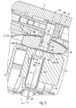
- einen wesentlichen Bereich der Axialkolbenmaschine in der Stellung gem. Fig. 1 in vergrößerter Darstellung;
- Fig. 4
- eine Steuerscheibe der Axialkolbenmaschine in der Vorderansicht;
- Fig. 5
- die Steuerscheibe in der Rückansicht;
- Fig. 6
- der in Fig. 3 mit X gekennzeichnete Bereich der Axialkolbenmaschine in abgewandelter Ausgestaltung.
- Fig. 1
- an axial piston according to the invention with adjustable throughput volume in axial section;
- Fig. 2
- a portion of the axial piston engine in a changed with respect to their flow rate position;
- Fig. 3
- a substantial portion of the axial piston machine in the position acc. Fig. 1 in an enlarged view;
- Fig. 4
- a control disk of the axial piston machine in front view;
- Fig. 5
- the control disk in the rear view;
- Fig. 6
- in Fig. 3 marked with X area of the axial piston machine in a modified embodiment.
Bei der beispielhaft dargestellten und in ihrer Gesamtheit mit 1 bezeichneten Axialkolbenmaschine handelt es sich um eine solche in Schrägachsenbauweise. Diese Bauweise weist ein geschlossenes Gehäuse 2 auf, mit einem topfförmigen Gehäuseteil 3, dessen Gehäuseinnenraum 4 durch ein sogenanntes Anschlußteil 5 lösbar verschlossen ist, das durch andeutungsweise dargestellte Schrauben 6 mit dem freien Rand des Gehäuseteils 3 verschraubt ist. Im Gehäuse 2 ist eine Triebscheibe oder Triebwelle 7 drehbar gelagert, die die eine Bodenwand 3a des topfförmigen Gehäuses 3 in einem Durchführungsloch 8 durchsetzt und darin drehbar gelagert ist, z. B. mittels Wälzlagern 9a, 9b, die im Durchführungsloch 8 sitzen.In the axial piston machine shown by way of example and designated in its entirety by 1, it is such a bent-axis design. This design has a closed
Beim vorliegenden Ausführungsbeispiel, bei dem die Triebscheibe drehbar gelagert ist, ist die Längsmittelachse 11 der Triebscheibe 7 zugleich ihre Drehachse. Axial neben der Triebscheibe 7 ist im Gehäuseinnenraum 4 ein Zylinderblock 12 mit einer Längsmittelachse 13 gelagert, die bezüglich der Längsmittelachse 11 der Triebscheibe 7 in einer beide Längsmittelachsen 11, 13 enthaltenden Schrägachsenebene schräg verläuft, so daß die Längsmittelachsen 11, 13 einen spitzen Winkel W1 einschließen, der zur der Triebscheibe 7 abgewandten Seite hin offen ist. Der Schnittpunkt der Längsmittelachsen 11, 13 ist mit 14 bezeichnet.In the present embodiment, in which the drive disk is rotatably mounted, the
Im Zylinderblock 12 sind auf seinem Querschnitt verteilt mehrere z. B. bezüglich der Mittelachse 13 parallel angeordnete Kolbenlöcher 15 angeordnet, die in Richtung auf die Triebscheibe 7 ausmünden, und in denen Kolben 16 hin und her verschiebbar gelagert sind, deren der Triebscheibe 7 zugewandte Enden allseitig schwenkbar an der Triebscheibe 7 abgestützt sind. Im Ausführungsbeispiel sind hierzu Kugelkalottenlager 17 zwischen den Kolben 16 und der Triebscheibe 7 vorgesehen.In the
An der der Triebscheibe 7 abgewandten Stirnseite des Zylinderblocks 12 ist eine Steuerscheibe 18 angeordnet, die durch eine Positioniervorrichtung 19 am Gehäuse 2 abgestützt ist und an ihrer dem Zylinderblock 12 zugewandten Seite ein Führungselement 21 mit einer Führungsmittelachse 22 für den Zylinderblock 12 aufweist. Die Führungsmittelachse 22 verläuft quer zur Steuerscheibe 18 und im mittleren Bereich der Steuerscheibe 18 sowie koaxial zur Längsmittelachse 13 des Zylinderblocks 12. Dieser ist in Richtung auf die Steuerscheibe 18 durch aneinander anliegende Führungsflächen 23a, 23b und quer zur Führungsmittelachse 22 durch das Führungselement 21 an der Steuerscheibe 18 abgestützt.At the
Durch eine Relativdrehung zwischen der Triebscheibe 7 und dem Zylinderblock 12 werden die Kolben 16 auf Grund des Vorhandenseins des Achsenwinkels W1 hin und her verschoben, wobei die Kolben 16 je nach Drehrichtung auf der einen Seite der Längsmittelachse 13 Fluid ansaugen und auf der anderen Seite verdrängen. Hierbei strömt der Fluidstrom von einem nicht dargestellten Einlaß durch auf beiden Seiten koaxial zur Führungsmittelachse 22 symmetrisch angeordnete Steuerkanäle 25 in der Steuerscheibe 18, durch sich zu den Steuerkanälen 25 erstreckende Kanäle 26 im Anschlußteil 5 und durch sich von den Steuerkanälen 25 zu den Kolbenlöchern 15 erstreckenden Kanäle 27 im Zylinderblock 12 zu einem ebenfalls am Anschlußteil 5 angeordneten, nicht dargestellten Auslaß.By a relative rotation between the
Beim Ausführungsbeispiel ist das Führungselement 21 dadurch gebildet, daß die Führungsflächen 23a, 23b konzentrisch zu der Führungsmittelachse 22 und der Längsmittelachse 13, vorzugsweise kugelabschnittförmig, gekrümmt sind, und zwar an der Stirnseite des Zylinderblocks 12 konkav gekrümmt sind und an der gegenüberliegenden Stirnseite der Steuerscheibe 18 konvex gekrümmt sind, so daß die Führungsfläche 23a ein erhabenes bzw. konvexes Führungselement 21 begrenzt, wie es an sich bekannt ist.In the exemplary embodiment, the
Die Positioniervorrichtung 19 ist durch ein Positionierelement 19a am Anschlußteil 5 und ein damit zusammenwirkendes Positionierelement 19b an der Steuerscheibe 18 gebildet. Die Positionierelemente 19a, 19b wirken derart formschlüssig zusammen, daß eine quer zur Führungsmittelachse 22 gerichtete Bewegung und eine vom Zylinderblock 12 abgewandte Bewegung der Steuerscheibe 18 durch die Positioniervorrichtung 19 am Anschlußteil 5 formschlüssig gesperrt ist. Die Positionierelemente 19a, 19b greifen längs einer Eingriffsachse 19c ineinander. Eine in einfacher Weise montierbare bzw. demontierbare Ausgestaltung der Positionierelemente 19a, 19b wird dann erzielt, wenn sie durch eine längs der Führungsmittelachse gerichtete Montage- bzw. Demontagebewegung der Steuerscheibe 18 bzw. des Anschlußteils 5 montier- bzw. demontierbar sind. Bei einer solchen Ausgestaltung ist das Positionierelement 19b an der Steuerscheibe 18 für das Positionierelement 19a am Anschlußteil 5 von der Anschlußseite her zugänglich, auf der sich das Anschlußteil 5 befindet.The
Beim Ausführungsbeispiel ist das Positionierelement 19b an der Steuerscheibe durch eine vom Anschlußteil 5 her offene und somit zugängliche Ausnehmung gebildet, in die ein vom Steuerteil 5 zur Steuerscheibe 18 hin abstehender Positionierzapfen mit geringem Bewegungsspiel einfaßt. Dabei ist die Positioniervorrichtung 19 so ausgebildet, daß die quer zur Steuerscheibe 18 gerichtete Mittelachse 19c der Positioniervorrichtung 19 bezüglich der Führungsmittelachse 22 in der beide Mittelachsen 11, 13 enthaltenden Schrägachsenebene E seitlich versetzt ist. Aus dem Versatzwinkel W2 ergibt sich das entsprechende Versatzmaß a. Folglich ist auch das Positionierelement 19a bezüglich der Führungsmittelachse 22 um den Versatzwinkel W2 seitlich versetzt. Der Versatzwinkel W2 ist kleiner als etwa 10° und beträgt vorzugsweise etwa 3°.In the embodiment, the
Die Positioniervorrichtung 19 umfaßt außerdem eine der Steuerscheibe 18 zugewandte Anlagefläche 19d an dem Anschlußteil 5. Die Steuerscheibe 18 liegt mit einer Anlagefläche 18a an ihrer dem Anschlußteil 5 zugewandten Stirnseite an der Anlagefläche 19d an und ist dadurch zur dem Zylinderblock 12 abgewandten Seite hin abgestützt.The
Außerdem ist die Positioniervorrichtung 19 so ausgebildet, daß die Steuerscheibe 18 aus der in Fig. 1 und 3 dargestellten Versatzstellung in eine in Fig. 2 dargestellte Versatzstellung montierbar ist, in der sie um die Führungsmittelachse 22 um 180° gedreht ist, und umgekehrt. Das Ummontieren der Steuerscheibe 18 in die in Fig. 1 und 2 dargestellten Stellungen führt zu einem seitlichen Versatz der Steuerscheibe 18 und des daran geführten Zylinderblocks 12, wobei dieser Versatz doppelt so groß ist, wie der durch den Versatzwinkel W2 gegebene Versatz a.In addition, the
Die soweit beschriebene Axialkolbenmaschine 1 ist somit durch ein Montieren der Steuerscheibe 18 in einer bestimmten Montagestellung oder durch eine Ummontieren der Steuerscheibe 18 in um 180° verdrehten Stellungen montierbar. In diesen Stellungen der Steuerscheibe 18 ist die Axialkolbenmaschine 1 auf zwei unterschiedlich große Durchsatzvolumen einstellbar und in einer Stufe verstellbar.The axial piston machine 1 described so far can thus be mounted by mounting the
Beim dargestellten Ausführungsbeispiel ist die Steuerscheibe 18 zusätzlich zu den vorbeschriebenen Stellungen in einer sich parallel zur Schrägachsenebene E erstreckende Schwenkführung 31 seitlich hin und her schwenkbar und feststellbar, wobei die Schwenkführung 31 um den Schnittpunkt 14 der Längsmittelachsen 11, 13 gekrümmt ist. Ferner ist eine Verstellvorrichtung 32 vorgesehen, mittels der die Steuerscheibe 18 in der Schwenkführung 31 in der Schrägachsenebene E hin und her zwischen einer Minimalstellung, z. B. mit einem Schwenkwinkel von 0° und einer Maximalstellung, z. B. mit einem Schwenkwinkel von 26°, stufenlos verstellbar und in der jeweiligen Schwenkstellung feststellbar ist.In the illustrated embodiment, the
Beim Ausführungsbeispiel ist die Schwenkführung 31 durch eine Führungsnut 31a in der dem Gehäuseinnenraum 4 zugewandten Wand des Anschlußteils 5 gebildet, wobei die Grundfläche der Führungsnut 31a durch die Anlagefläche 19d gebildet ist und um den Schnittpunkt 14 konkav gekrümmt ist und eine gekrümmte Führungs- und Anlagefläche 19d bildet, an der die Steuerscheibe 18 mit ihrer entsprechend konvex gekrümmten Anlagefläche 18a gleitbar anliegt. Es ist außerdem die Verstellvorrichtung 32 in das Anschlußteil 5 integriert und z. B. durch einen Verstellschieber 32a gebildet, der hydraulisch quer zur Führungsmittelachse 22 und in der Schrägachsenebene E in einer Schieberführung hin und her gezielt verschiebbar und in der jeweiligen Einstellung feststellbar ist. Das Anschlußteil 5 ist bezüglich der Mittelachse 11 in der Schrägachsenebene schräg angeordnet und schließt mit der Mittelachse 11 einen spitzen Winkel W3 ein, der dem halben Winkel des Schwenkwinkelbereichs entspricht und beim Ausführungsbeispiel etwa 16° beträgt. Dabei beträgt W3=16° für beide beispielhaften Verstellbereiche 0-26° und 6-32°.In the embodiment, the pivot guide 31 is formed by a guide groove 31a in the
Das am Anschlußteil 5 angeordnete Positionierelement 19a ist beim Ausführungsbeispiel am Verstellschieber 32a befestigt und mit diesem in einem entsprechenden Freiraum 34 bzw. Schlitz hin und her verschiebbar, wobei durch die Wirkverbindung der Positionierelemente 19a, 19b die Steuerscheibe 18 mitbewegt wird. Um trotz der unterschiedlichen Bewegungsrichtungen zwischen den Positionierelementen 19a, 19b (gerade, gekrümmt) eine Positionierung in der quer zur Führungsmittelachse 22 gerichteten Verschiebung in der Schrägachsenebene E zu gewährleisten, taucht das zapfenförmige Positionierelement 19a mit einem kreisförmig gerundeten Positionierkopf 19e in die das Gegenpositionierteil bildende Ausnehmung 19f in der Steuerscheibe 18 ein.The arranged on the connecting
Bei einer solchen stufenlos verstellbaren Axialkolbenmaschine 1 ermöglicht die erfindungsgemäße Ausgestaltung entweder ein Verringern oder Vergrößern des Durchsatzvolumens der Axialkolbenmaschine oder ein von vornherein gezieltes Einstellen der Axialkolbenmaschine durch eine entsprechende Ummontage bzw. Erstmontage.In such a continuously variable axial piston engine 1 embodiment of the invention allows either a reduction or increase in the throughput volume of the axial piston or a targeted from the outset setting the axial piston machine by a corresponding Ummontage or initial assembly.
Ein besonderer Vorteil der erfindungsgemäßen Ausgestaltung ist darin zu sehen, daß die erfindungsgemäße Ausgestaltung sich auf die Ausbildung der Steuerscheibe beschränkt und deshalb die erfindungsgemäße Ausgestaltung sich für eine Umrüstung der Kolbenmaschine eignet, ohne daß deren andere Teile verändert werden müssen. So läßt sich z. B. durch einen entsprechenden Versatz der Steuerscheibe der Verstellbereich der Verstellvorrichtung um das Versatzmaß vergrößern, ohne daß es einer entsprechenden Vergrößerung der Verstellvorrichtung selbst bedarf. Dies wird deutlich, wenn man berücksichtigt, daß bei einer Verstellvorrichtung mit einem Verstellbereich von z. B. etwa 0 bis 26° die erfindungsgemäße Ausgestaltung in der einen Stellung der Steuerscheibe diesen Verstellbereich beibehält und in der anderen Stellung zu einem Verstellbereich führt, der um das Versatzmaß der Steuerscheibe vergrößert ist, jedoch um das Versatzmaß vor den 0-Punkt der Verstellvorrichtung endet. Auch wenn die Axialkolbenmaschine von vornherein nur mit einer der beiden Schwenkwinkelbereiche montiert wird, lassen sich die beiden Schwenkwinkelbereiche mit einem hohen Gleichteileanteil realisieren.A particular advantage of the embodiment according to the invention is the fact that the embodiment of the invention is limited to the formation of the control disk and therefore the embodiment of the invention is suitable for retrofitting the piston engine without the other parts must be changed. So can be z. B. by a corresponding offset of the control disk of the adjustment of the adjustment by the offset size increase, without the need for a corresponding increase in the adjustment itself. This becomes clear when one considers that in an adjustment with an adjustment range of z. B. about 0 to 26 ° the According to the invention configuration in a position of the control disc this adjustment area maintains and leads in the other position to an adjustment, which is increased by the offset of the control disc, but ends by the offset dimension before the 0-point of the adjustment. Even if the axial piston machine is mounted from the outset only with one of the two pivoting angle ranges, the two pivoting angle ranges can be realized with a high proportion of identical parts.
Die Endstellungen des Schwenkbereichs können durch Anschläge A1, A2 begrenzt sein, die verstellbar sind und als Begrenzungsanschläge für den Verstellschieber 32a in das Anschlußteil 5 integriert sein können. Beim Ausführungsbeispiel ist ein Minimalanschlag A1 und ein Maximalanschlage A2 jeweils durch eine Einstellschraube 35 gebildet, die etwa in der Schrägachsenebene E die Umfangswand des Gehäuses 2 in einem Gewindeloch 36 durchsetzt, in den Gehäuseinnenraum 4 hineinragt und von außen durch ein an ein Drehangriffsglied, z. B. ein Schlitz 37, angreifbares Drehwerkzeug drehbar und feststellbar ist, z. B. mittels einer Kontermutter 38.The end positions of the pivoting range can be limited by stops A1, A2, which are adjustable and can be integrated as limiting stops for the adjusting
Bei den vorbeschriebenen Ausführungsbeispielen ist die Steuerscheibe 18 in jeder Schwenkposition bezüglich dem Zylinderblock 12 in der Schwenkebene E unverschiebbar positioniert. Somit ist zwischen der Steuerscheibe 18 und dem Zylinderblock 12 eine Positioniervorrichtung 41 wirksam, die diese beiden Teile in der Schwenkebene E unverschiebbar aneinander positioniert. Diese Positionierung wird aufgrund der in der Schwenkebene E konvexen Form der Steuerscheibe 18 und konkaven Form des Zylinderblocks 12 bewirkt. Deshalb ist die Steuerscheibe 18 in der Lage, bei ihrer Verschiebung in der Schwenkebene E den Zylinderblock 12 mitzunehmen, wobei die Positioniervorrichtung 4i als Mitnahmevorrichtung wirksam ist. Das Führungselement 21 ermöglicht dabei das Drehen des Zylinderblocks 12 in der Positionierung.In the embodiments described above, the
Diese Positioniervorrichtung 41 ist aufgrund der verhältnismäßig geringen Bogenform der Führungsflächen 23a, 23b anfällig für zwischen der Steuerscheibe 18 und dem Zylinderblock 12 wirksamen Klemmwirkungen.This positioning device 41 is due to the relatively small arc shape of the guide surfaces 23a, 23b prone to between the
Es ist deshalb vorteilhaft, die zwischen der Steuerscheibe 18 und dem Zylinderblock 12 wirksame Positioniervorrichtung 41 so zu stabilisieren, daß die vorbeschriebenen Klemmwirkungen und ein daraus resultierender höherer Verschleiß und Erwärmung vermindert oder verhindert werden können.It is therefore advantageous to stabilize the positioning device 41, which acts between the
Bei dem Ausführungsbeispiel nach Fig. 6 ist die Positioniervorrichtung 41 durch eine zusätzliche zwischen der Steuerscheibe 18 und dem Zylinderblock 12 wirksame Zapfenverbindung gebildet mit einem Positionierzapfen 42, der jeweils passend in Positionierausnehmungen 42a, 42b in der Steuerscheibe 18 und im Zylinderblock 12 einfaßt und dabei die Fuge 31b dazwischen durchsetzt. Außerdem sind die in die Positionierausnehmungen 42a, 42b einfassenden Zapfenabschnitte 42c, 42d des Positionierzapfens 42 um das Versatzmaß a bzw. den Winkel W2 zueinander versetzt bzw. abgekröpft angeordnet, und eine oder beide dieser Zapfenverbindungen ist bzw. sind in den um 180° verdrehten Stellungen der Steuerscheibe 18 montierbar. Die Positionierausnehmungen 42a, 42b und die Zapfenabschnitte 42c, 42d weisen vorzugsweise einen runden Querschnitt auf. Aufgrund des Versatzes a ist der Positionierzapfen 42 bezüglich der Steuerscheibe 18 undrehbar in der Steuerscheibe 18 gelagert. Im Übergangsbereich 42g zwischen den Zapfenabschnitten 42a, 42b kann der Positionierstift 42 schräg verlaufende Seitenabschnitte aufweisen, die vorzugsweise konvex bzw. konkav gerundet in die Zapfenabschnitte 42c, 42d übergehen, wie es die Zeichnung zeigt. Die Positionierausnehmung 42b bildet ein Drehlager 40 für den Zylinderblock 12. Es kann sich um ein Wälz- oder Gleitlager handeln, das eine an einem der Drehlagerteile befestigte Gleitbuchse 12a aufweisen kann.In the embodiment of FIG. 6, the positioning device 41 is formed by an additional between the
Beim Ausführungsbeispiel nach Fig. 6 ist die Positionierausnehmung 19b im Zapfenabschnitt 42c angeordnet, wobei sie bezüglich ihrer Querschnittsform und -größe an die Querschnittsgröße und Form des Positionierelements 19a angepaßt ist und durch ein stirnseitig offenes Sackloch gebildet sein kann. Die Positionierausnehmung 19b ist vorzugsweise durch einen längs verlaufenden Kanal gebildet und zu einem einen mittleren Führungszapfen 16a aufnehmenden Führungsloch 15a hin offen. Hierdurch wird die Schmierung der Positionierelemente 19a, 19b verbessert.In the embodiment according to FIG. 6, the
Im übrigen können die Positionierelemente 19a, 19b wie beim Ausführungsbeispiel nach Fig. 3 ausgebildet sein, nämlich mit einer Taille 19h am Positionierkopf 19e und einer Ausnehmungserweiterung 19i am dem Gehäuse bzw. Anschlußteil 5 zugewandten Lochrand, um den zur Verfügung stehenden Schwenkbereich zu vergrößern.Moreover, the
Eine zwischen der Steuerscheibe 18 und dem Zylinderblock 12 angeordnete Gleitschicht 44 aus gleitfreudigem und/oder verschleißfestem Material kann durch eine Scheibe gebildet sein, die an der Steuerscheibe 18 befestigt sein kann, z.B. durch Löten, Schweißen oder Kleben. Ein von dem Positionierzapfen 42 durchsetztes Loch 44a in der Scheibe ist so groß, daß der Übergangsbereich 42g darin in den beiden Versatzstellungen Freiraum hat.A sliding
Beim Ausführungsbeispiel nach Fig. 6 sind die Führungsflächen 23a, 23b im Gegensatz zum vorbeschriebenen Ausführungsbeispiel ebene Flächen, sie können aber auch kugelabschnittförmig konkav bzw. konvex ausgebildet sein, wie es beim vorbeschriebenen Ausführungsbeispiel der Fall ist.In the embodiment of Fig. 6, the guide surfaces 23a, 23b in contrast to the above-described embodiment, flat surfaces, but they can also be spherical section-shaped concave or convex, as is the case in the above-described embodiment.
Die Positionierausnehmung 42b und der Zapfenabschnitt 42d sind vorzugsweise koaxial zur Längsmittelachse 13 des Zylinderblocks 12 angeordnet. Die Positionierausnehmung 42a und der Positionierzapfen 42c sowie die Positionierausnehmung 19b können bezüglich der Längsmittelachse 13 und dem Versatz a parallel versetzt sein. Beim Ausführungsbeispiel sind die Positionierausnehmung 42a, der darin befindliche Zapfenabschnitt 42c und die Positionierausnehmung 19b bezüglich der Längsmittelachse 13 um den Winkel W2 verdreht zueinander angeordnet.The
Das Ummontieren der Steuerscheibe 18 kann bei abgenommenem Gehäusedeckel bzw. Anschlußteil 5 dadurch erfolgen, daß die Steuerscheibe 18 vom Zapfenabschnitt 42c abgehoben, um 180° etwa um die Mittelachse 13 gedreht und wieder aufgesetzt wird, oder daß die Steuerscheibe 18 mit dem Positionierzapfen 42 aus der Positionierausnehmung 42b ausgehoben, um 180° etwa um die Mittelachse 13 gedreht und wieder in die Positionierausnehmung 42b eingesetzt wird. Sofern es möglich ist, kann die Ummontage auch dadurch erfolgen, daß der Positionierzapfen 42 um 180° in der Positionierausnehmung 42b gedreht wird.The remounting of the
Claims (19)
- Axial piston machine (1) with a housing (2), in which a drive disc (7) and a cylinder block (12) axially arranged in its vicinity are rotatably mounted relative to one another about longitudinal centre axes (11, 13), which extend obliquely to one another by an angle (W1) in an oblique axis plane (E),
a plurality of piston bores (15) being arranged in the cylinder block (12) and in which pistons (16) are displaceably guided axially to and fro, of which the piston ends facing the drive disc (7) are supported in a universally pivotal manner on the drive disc (7), on the front face of the cylinder block (12) facing away from the drive disc (7) a cam disc (18) being arranged which is supported on the housing (2) by a first positioning device (19) with positively cooperating positioning elements (19a, 19b) and on its face facing the cylinder block (12) comprising a guide element (21) with a guide centre axis (22) extending coaxially to the longitudinal centre axis (13) of the cylinder block (12),
characterised in that,
of the positioning elements (19a, 19b), the positioning element (19b) arranged on the cam disc (18) is offset transversely to the guide centre axis (22) of the guide element (21) in the oblique axis plane (E) and the cam disc (18) is able to be installed in a further position rotated by approximately 180° about the guide centre axis (22) of the guide element (21), in which the positioning elements (19a, 19b) also cooperate. - Axial piston machine according to claim 1,
characterised in that
the first positioning device (19) comprises a pivoting guide (31) curved about the intersection (14) between the longitudinal centre axes (11, 13) of the drive disc (7) and the cylinder drum (12) and in which the cam disc (18) can be adjusted in the oblique axis plane (E) by an adjustment device (32) and can be fixed in the respective adjustment position. - Axial piston machine according to claim 1 or 2,
characterised in that
the positioning element (19b) is offset relative to the guide centre axis (22) by an offset angle (W2) which is smaller than approximately 10°. - Axial piston machine according to claim 3,
characterised in that
the offset angle (W2) is approximately 3°. - Axial piston machine according to any of the preceding claims,
characterised in that
the guide element (21) comprises a guide surface (23a) rotationally-symmetrically curved about the guide centre axis (22) which preferably is a raised portion of the cam disc (18) or is planar and in that the front surface of the cylinder block (12) facing the cam disc (18) is adapted to the form of the guide surface (23a). - Axial piston machine according to any of the preceding claims,
characterised in that
the positioning element (19b) arranged on the cam disc (18) is a recess in which an adjusting pin is held as a second positioning element (19a). - Axial piston machine according to any of the preceding claims 1 to 6,
characterised in that
the cylinder block (12) is supported by the guide element (21) transversely to its longitudinal centre axis (13) on the cam disc (18). - Axial piston machine according to any of the preceding claims,
characterised in that
the cylinder block (12) is positioned positively against relative displacement in the oblique axis plane (E) by a second positioning device (41). - Axial piston machine according to claim 8,
characterised in that
the second positioning device (41) is formed by a positioning pin (42) which is seated with a pin portion (42c) in a positioning recess (42a) in the cam disc (18) and is seated in a positioning recess (42b) of the cylinder block (12) with a positioning pin (42d) offset in the oblique axis plane (E) by the offset (a). - Axial piston machine according to claim 9,
characterised in that
the pin portion (42d) seated in the cylinder block (12) is rotatably mounted in the cylinder block (12) by a rotary bearing (40). - Axial piston machine according to claim 9 or 10,
characterised in that
the pin portion (42c) seated in the cam disc (18) forms a positioning element for the first positioning device (19). - Axial piston machine according to claim 11,
characterised in that
the positioning element is formed by a positioning recess (19b) open on the front face. - Axial piston machine according to any of claims 9 to 12,
characterised in that
between the cam disc (18) and the cylinder block (12) a disc (44) with a hole (44a) is arranged for the positioning pin (42) which preferably is large enough so that in the offset positions of the cam disc (18) a transitional region (42g) of the positioning pin (42) preferably extending obliquely has a free space in the hole (44a). - Axial piston machine according to any of claims 9 to 13,
characterised in that
the positioning pin (42) comprises an elongate through hole which preferably opens out into the positioning recess (19b). - Cam disc (18) for an
axial piston machine (1) with a housing (2) in which a drive disc (7) and a cylinder block (12) axially arranged in its vicinity with pistons (16) axially displaceable therein, are rotatably mounted relative to one another about longitudinal centre axes(11, 13), which extend obliquely to one another in an oblique axis plane (E) by an angle (W1), the cam disc (18) comprising- a guide element (21) arranged on a first face of the cam disc (18) with a guide centre axis (22) which extends transversely to the cam disc (18) and in its centre region,- a pivoting guide surface (18a) on the second face of the cam disc (18) opposing the first face, this pivoting guide surface (18a) being curved in the form of a circular arc shape in a convex manner about an intersection (14) located on the guide centre axis (22) and parallel to an oblique axis plane (E) containing the guide centre axis (22),- and a positioning element (19b) on the cam disc (18) for positioning the cam disc (18) on the housing (2),characterised in that
the positioning element (19b) on the cam disc (18) is offset transversely to the guide centre axis (22) of the guide element (21) in the oblique axis plane (E). - Cam disc according to claim 15,
characterised in that
the positioning element (19b) is offset relative to the guide centre axis (22) by an offset angle (W2) which is smaller than approximately 10°. - Cam disc according to claim 16,
characterised in that the offset angle (W2) is approximately 3°. - Cam disc according to any of claims 15 to 17,
characterised in that
the guide element (21) comprises a guide surface (23a) rotationally-symmetrically curved about the guide centre axis (22) and which preferably is a raised portion of the cam disc (18). - Cam disc according to any of claims 15 to 18,
characterised in that
the positioning element (19b) arranged on the cam disc (18) is a recess in which an adjusting pin (19a) can be held.
Applications Claiming Priority (3)
| Application Number | Priority Date | Filing Date | Title |
|---|---|---|---|
| DE10326059 | 2003-06-11 | ||
| DE10347086A DE10347086A1 (en) | 2003-06-11 | 2003-10-10 | Axial piston machine with offset positioning and control disc for such an axial piston machine |
| PCT/EP2004/003250 WO2004109107A1 (en) | 2003-06-11 | 2004-03-26 | Axial piston machine with offset positioning element and cam disk for such an axial piston machine |
Publications (2)
| Publication Number | Publication Date |
|---|---|
| EP1631744A1 EP1631744A1 (en) | 2006-03-08 |
| EP1631744B1 true EP1631744B1 (en) | 2007-02-28 |
Family
ID=33512389
Family Applications (1)
| Application Number | Title | Priority Date | Filing Date |
|---|---|---|---|
| EP04723575A Expired - Lifetime EP1631744B1 (en) | 2003-06-11 | 2004-03-26 | Axial piston machine with offset positioning element and cam disk for such an axial piston machine |
Country Status (4)
| Country | Link |
|---|---|
| US (1) | US7363849B2 (en) |
| EP (1) | EP1631744B1 (en) |
| DE (1) | DE502004003059D1 (en) |
| WO (1) | WO2004109107A1 (en) |
Families Citing this family (7)
| Publication number | Priority date | Publication date | Assignee | Title |
|---|---|---|---|---|
| KR100918603B1 (en) * | 2005-11-24 | 2009-09-25 | 가부시키가이샤 고마쓰 세이사쿠쇼 | Inclined shaft-type variable displacement pump/motor |
| JP5425722B2 (en) * | 2010-06-23 | 2014-02-26 | 日立建機株式会社 | Oblique shaft type hydraulic rotating machine |
| DE102014104951A1 (en) | 2014-04-08 | 2015-10-08 | Linde Hydraulics Gmbh & Co. Kg | Axial piston machine in bent axis design |
| DE102015107343A1 (en) * | 2015-05-11 | 2016-11-17 | Linde Hydraulics Gmbh & Co. Kg | Hydrostatic axial piston machine in bent axis design |
| DE102016100920A1 (en) | 2015-11-11 | 2017-05-11 | Linde Hydraulics Gmbh & Co. Kg | Hydrostatic axial piston machine in bent axis design |
| EP3168469B1 (en) | 2015-11-11 | 2019-06-05 | Linde Hydraulics GmbH & Co. KG | Hydrostatische axialkolbenmaschine in schrägachsenbauweise |
| CN112459981A (en) * | 2020-11-29 | 2021-03-09 | 江苏可奈力机械制造有限公司 | Slide inclined shaft variable high-pressure plunger pump |
Family Cites Families (7)
| Publication number | Priority date | Publication date | Assignee | Title |
|---|---|---|---|---|
| US2968286A (en) * | 1956-05-29 | 1961-01-17 | Reiners Walter | Hydraulic axial-piston machine |
| DE19649195C1 (en) * | 1996-11-27 | 1998-01-08 | Brueninghaus Hydromatik Gmbh | Axial piston machine with swivelling cylinder drum |
| DE19833711A1 (en) | 1998-07-27 | 2000-02-10 | Brueninghaus Hydromatik Gmbh | Hydrostatic axial piston machine with a tracking device for a washer |
| DE19842029B4 (en) * | 1998-09-14 | 2005-02-17 | Sauer-Sundstrand Gmbh & Co. | Adjustment of hydrostatic axial piston machines by means of stepper motor |
| DE19857366C2 (en) | 1998-12-11 | 2000-10-19 | Brueninghaus Hydromatik Gmbh | Axial piston machine |
| DE10030147C1 (en) | 2000-06-20 | 2002-06-06 | Brueninghaus Hydromatik Gmbh | axial piston |
| DE10119236C1 (en) | 2001-04-19 | 2002-12-12 | Brueninghaus Hydromatik Gmbh | Axial piston machine with an inclined axis design, with a swivel angle sensor |
-
2004
- 2004-03-26 DE DE502004003059T patent/DE502004003059D1/en not_active Expired - Lifetime
- 2004-03-26 EP EP04723575A patent/EP1631744B1/en not_active Expired - Lifetime
- 2004-03-26 US US10/550,292 patent/US7363849B2/en not_active Expired - Fee Related
- 2004-03-26 WO PCT/EP2004/003250 patent/WO2004109107A1/en active IP Right Grant
Also Published As
| Publication number | Publication date |
|---|---|
| US20060180016A1 (en) | 2006-08-17 |
| WO2004109107A1 (en) | 2004-12-16 |
| US7363849B2 (en) | 2008-04-29 |
| DE502004003059D1 (en) | 2007-04-12 |
| EP1631744A1 (en) | 2006-03-08 |
Similar Documents
| Publication | Publication Date | Title |
|---|---|---|
| DE19937560B4 (en) | Orbital reciprocating saw | |
| EP0372376B1 (en) | Oscillating device | |
| DE3545200C2 (en) | ||
| DE2533498C2 (en) | Arrangement and design of the swivel vane motor on a hydraulic axial piston machine | |
| DE3942189C1 (en) | ||
| DE69301254T2 (en) | Hydraulic piston pump with inlet valves | |
| DE69604972T2 (en) | Swashplate compressor with variable delivery capacity and with an improved joint device to support the inclination of a swashplate | |
| DE69026841T2 (en) | SLAVE PISTON PUMP OR ENGINE | |
| DE4328114A1 (en) | Variable capacity swashplate compressor - has hinge device with support arm, main guide pin and auxiliary guide pin | |
| DE69524783T2 (en) | TILTING ANGLE CONTROL DEVICE FOR A SWASH DISC PUMP | |
| EP1631744B1 (en) | Axial piston machine with offset positioning element and cam disk for such an axial piston machine | |
| DE2115350C3 (en) | Device for noise reduction on a slot-controlled axial piston pump | |
| DE4400911A1 (en) | Rake adjustment for vehicle seat with seat depth adjustment | |
| DE19755386C2 (en) | Hydrostatic machine with a rotatably mounted cylinder drum and an adjustable swivel disc | |
| WO2007014768A1 (en) | Axial piston machine having an elongated guide element for a cage segment | |
| EP0841447A1 (en) | Adjustable dooropener with a pivoting blocking piece | |
| EP0525507B1 (en) | Device for adjusting the actuator for displacement volume control of a hydrostatic machine | |
| DE10347086A1 (en) | Axial piston machine with offset positioning and control disc for such an axial piston machine | |
| EP0309762B1 (en) | Adjustable axial piston machine with a swash plate | |
| DE3728448C2 (en) | ||
| EP1251270B1 (en) | Variable capacity axial piston machine with inclination angle sensor | |
| DE19857366C2 (en) | Axial piston machine | |
| DE19833711A1 (en) | Hydrostatic axial piston machine with a tracking device for a washer | |
| DE19527649A1 (en) | Axial piston machine with concentric cylinders - has guide device effective over entire lifting length of piston | |
| DE10304157A1 (en) | Pendelhubschalter |
Legal Events
| Date | Code | Title | Description |
|---|---|---|---|
| PUAI | Public reference made under article 153(3) epc to a published international application that has entered the european phase |
Free format text: ORIGINAL CODE: 0009012 |
|
| 17P | Request for examination filed |
Effective date: 20050331 |
|
| AK | Designated contracting states |
Kind code of ref document: A1 Designated state(s): DE FR GB IT SE SK |
|
| DAX | Request for extension of the european patent (deleted) | ||
| RBV | Designated contracting states (corrected) |
Designated state(s): DE FR GB IT SE SK |
|
| GRAP | Despatch of communication of intention to grant a patent |
Free format text: ORIGINAL CODE: EPIDOSNIGR1 |
|
| GRAS | Grant fee paid |
Free format text: ORIGINAL CODE: EPIDOSNIGR3 |
|
| GRAA | (expected) grant |
Free format text: ORIGINAL CODE: 0009210 |
|
| AK | Designated contracting states |
Kind code of ref document: B1 Designated state(s): DE FR GB IT SE SK |
|
| REG | Reference to a national code |
Ref country code: GB Ref legal event code: FG4D Free format text: NOT ENGLISH |
|
| GBT | Gb: translation of ep patent filed (gb section 77(6)(a)/1977) |
Effective date: 20070228 |
|
| REF | Corresponds to: |
Ref document number: 502004003059 Country of ref document: DE Date of ref document: 20070412 Kind code of ref document: P |
|
| REG | Reference to a national code |
Ref country code: SE Ref legal event code: TRGR |
|
| ET | Fr: translation filed | ||
| PLBE | No opposition filed within time limit |
Free format text: ORIGINAL CODE: 0009261 |
|
| STAA | Information on the status of an ep patent application or granted ep patent |
Free format text: STATUS: NO OPPOSITION FILED WITHIN TIME LIMIT |
|
| 26N | No opposition filed |
Effective date: 20071129 |
|
| PGFP | Annual fee paid to national office [announced via postgrant information from national office to epo] |
Ref country code: SE Payment date: 20091222 Year of fee payment: 7 |
|
| PGFP | Annual fee paid to national office [announced via postgrant information from national office to epo] |
Ref country code: FR Payment date: 20100331 Year of fee payment: 7 Ref country code: SK Payment date: 20100324 Year of fee payment: 7 |
|
| PGFP | Annual fee paid to national office [announced via postgrant information from national office to epo] |
Ref country code: GB Payment date: 20100324 Year of fee payment: 7 |
|
| REG | Reference to a national code |
Ref country code: SE Ref legal event code: EUG |
|
| GBPC | Gb: european patent ceased through non-payment of renewal fee |
Effective date: 20110326 |
|
| REG | Reference to a national code |
Ref country code: SK Ref legal event code: MM4A Ref document number: E 1833 Country of ref document: SK Effective date: 20110326 |
|
| REG | Reference to a national code |
Ref country code: FR Ref legal event code: ST Effective date: 20111130 |
|
| PG25 | Lapsed in a contracting state [announced via postgrant information from national office to epo] |
Ref country code: FR Free format text: LAPSE BECAUSE OF NON-PAYMENT OF DUE FEES Effective date: 20110331 |
|
| PG25 | Lapsed in a contracting state [announced via postgrant information from national office to epo] |
Ref country code: SK Free format text: LAPSE BECAUSE OF NON-PAYMENT OF DUE FEES Effective date: 20110326 Ref country code: GB Free format text: LAPSE BECAUSE OF NON-PAYMENT OF DUE FEES Effective date: 20110326 |
|
| PGFP | Annual fee paid to national office [announced via postgrant information from national office to epo] |
Ref country code: IT Payment date: 20120327 Year of fee payment: 9 |
|
| PG25 | Lapsed in a contracting state [announced via postgrant information from national office to epo] |
Ref country code: SE Free format text: LAPSE BECAUSE OF NON-PAYMENT OF DUE FEES Effective date: 20110327 |
|
| PG25 | Lapsed in a contracting state [announced via postgrant information from national office to epo] |
Ref country code: IT Free format text: LAPSE BECAUSE OF NON-PAYMENT OF DUE FEES Effective date: 20140326 |
|
| PGFP | Annual fee paid to national office [announced via postgrant information from national office to epo] |
Ref country code: DE Payment date: 20150521 Year of fee payment: 12 |
|
| REG | Reference to a national code |
Ref country code: DE Ref legal event code: R119 Ref document number: 502004003059 Country of ref document: DE |
|
| PG25 | Lapsed in a contracting state [announced via postgrant information from national office to epo] |
Ref country code: DE Free format text: LAPSE BECAUSE OF NON-PAYMENT OF DUE FEES Effective date: 20161001 |