EP1631725B1 - Wear assembly for excavator digging edge - Google Patents
Wear assembly for excavator digging edge Download PDFInfo
- Publication number
- EP1631725B1 EP1631725B1 EP04760540.7A EP04760540A EP1631725B1 EP 1631725 B1 EP1631725 B1 EP 1631725B1 EP 04760540 A EP04760540 A EP 04760540A EP 1631725 B1 EP1631725 B1 EP 1631725B1
- Authority
- EP
- European Patent Office
- Prior art keywords
- lip
- boss
- wear
- accordance
- lock
- Prior art date
- Legal status (The legal status is an assumption and is not a legal conclusion. Google has not performed a legal analysis and makes no representation as to the accuracy of the status listed.)
- Expired - Lifetime
Links
- 238000010276 construction Methods 0.000 claims description 11
- 235000020637 scallop Nutrition 0.000 description 13
- 241000237503 Pectinidae Species 0.000 description 8
- 229920001971 elastomer Polymers 0.000 description 8
- 239000000806 elastomer Substances 0.000 description 7
- 210000002105 tongue Anatomy 0.000 description 7
- 241000237509 Patinopecten sp. Species 0.000 description 5
- 239000000463 material Substances 0.000 description 4
- 230000037431 insertion Effects 0.000 description 3
- 238000003780 insertion Methods 0.000 description 3
- 229910000831 Steel Inorganic materials 0.000 description 2
- 230000015572 biosynthetic process Effects 0.000 description 2
- 230000000295 complement effect Effects 0.000 description 2
- 230000001419 dependent effect Effects 0.000 description 2
- 239000013536 elastomeric material Substances 0.000 description 2
- 230000002441 reversible effect Effects 0.000 description 2
- 239000010959 steel Substances 0.000 description 2
- 239000000853 adhesive Substances 0.000 description 1
- 230000001070 adhesive effect Effects 0.000 description 1
- 230000000712 assembly Effects 0.000 description 1
- 238000000429 assembly Methods 0.000 description 1
- 230000008878 coupling Effects 0.000 description 1
- 238000010168 coupling process Methods 0.000 description 1
- 238000005859 coupling reaction Methods 0.000 description 1
- 230000008030 elimination Effects 0.000 description 1
- 238000003379 elimination reaction Methods 0.000 description 1
- 238000004519 manufacturing process Methods 0.000 description 1
- 230000013011 mating Effects 0.000 description 1
- 238000000465 moulding Methods 0.000 description 1
- 230000002028 premature Effects 0.000 description 1
- 230000003313 weakening effect Effects 0.000 description 1
- 238000003466 welding Methods 0.000 description 1
- 239000002023 wood Substances 0.000 description 1
Images


Classifications
-
- E—FIXED CONSTRUCTIONS
- E02—HYDRAULIC ENGINEERING; FOUNDATIONS; SOIL SHIFTING
- E02F—DREDGING; SOIL-SHIFTING
- E02F3/00—Dredgers; Soil-shifting machines
- E02F3/04—Dredgers; Soil-shifting machines mechanically-driven
- E02F3/28—Dredgers; Soil-shifting machines mechanically-driven with digging tools mounted on a dipper- or bucket-arm, i.e. there is either one arm or a pair of arms, e.g. dippers, buckets
- E02F3/36—Component parts
-
- E—FIXED CONSTRUCTIONS
- E02—HYDRAULIC ENGINEERING; FOUNDATIONS; SOIL SHIFTING
- E02F—DREDGING; SOIL-SHIFTING
- E02F3/00—Dredgers; Soil-shifting machines
- E02F3/04—Dredgers; Soil-shifting machines mechanically-driven
- E02F3/76—Graders, bulldozers, or the like with scraper plates or ploughshare-like elements; Levelling scarifying devices
- E02F3/80—Component parts
- E02F3/815—Blades; Levelling or scarifying tools
- E02F3/8152—Attachments therefor, e.g. wear resisting parts, cutting edges
-
- E—FIXED CONSTRUCTIONS
- E02—HYDRAULIC ENGINEERING; FOUNDATIONS; SOIL SHIFTING
- E02F—DREDGING; SOIL-SHIFTING
- E02F9/00—Component parts of dredgers or soil-shifting machines, not restricted to one of the kinds covered by groups E02F3/00 - E02F7/00
- E02F9/28—Small metalwork for digging elements, e.g. teeth scraper bits
- E02F9/2808—Teeth
- E02F9/2816—Mountings therefor
- E02F9/2825—Mountings therefor using adapters
-
- E—FIXED CONSTRUCTIONS
- E02—HYDRAULIC ENGINEERING; FOUNDATIONS; SOIL SHIFTING
- E02F—DREDGING; SOIL-SHIFTING
- E02F9/00—Component parts of dredgers or soil-shifting machines, not restricted to one of the kinds covered by groups E02F3/00 - E02F7/00
- E02F9/28—Small metalwork for digging elements, e.g. teeth scraper bits
- E02F9/2808—Teeth
- E02F9/2816—Mountings therefor
- E02F9/2833—Retaining means, e.g. pins
- E02F9/2841—Retaining means, e.g. pins resilient
-
- E—FIXED CONSTRUCTIONS
- E02—HYDRAULIC ENGINEERING; FOUNDATIONS; SOIL SHIFTING
- E02F—DREDGING; SOIL-SHIFTING
- E02F9/00—Component parts of dredgers or soil-shifting machines, not restricted to one of the kinds covered by groups E02F3/00 - E02F7/00
- E02F9/28—Small metalwork for digging elements, e.g. teeth scraper bits
- E02F9/2808—Teeth
- E02F9/2858—Teeth characterised by shape
-
- E—FIXED CONSTRUCTIONS
- E02—HYDRAULIC ENGINEERING; FOUNDATIONS; SOIL SHIFTING
- E02F—DREDGING; SOIL-SHIFTING
- E02F9/00—Component parts of dredgers or soil-shifting machines, not restricted to one of the kinds covered by groups E02F3/00 - E02F7/00
- E02F9/28—Small metalwork for digging elements, e.g. teeth scraper bits
- E02F9/2883—Wear elements for buckets or implements in general
-
- Y—GENERAL TAGGING OF NEW TECHNOLOGICAL DEVELOPMENTS; GENERAL TAGGING OF CROSS-SECTIONAL TECHNOLOGIES SPANNING OVER SEVERAL SECTIONS OF THE IPC; TECHNICAL SUBJECTS COVERED BY FORMER USPC CROSS-REFERENCE ART COLLECTIONS [XRACs] AND DIGESTS
- Y10—TECHNICAL SUBJECTS COVERED BY FORMER USPC
- Y10T—TECHNICAL SUBJECTS COVERED BY FORMER US CLASSIFICATION
- Y10T403/00—Joints and connections
- Y10T403/70—Interfitted members
- Y10T403/7075—Interfitted members including discrete retainer
- Y10T403/7077—Interfitted members including discrete retainer for telescoping members
- Y10T403/7079—Transverse pin
Description
- The present invention pertains to a wear assembly for protecting the front edge of a structure subjected to wear, and is particularly suited for use along the front digging edge of an excavating bucket or the like.
- Excavating buckets and other excavating equipment are typically subjected to harsh conditions. A series of wear members are usually provided to protect the digging edges from premature wear. Wear members have been secured to the digging edge in many different ways.
- For example, in
U.S. Patent No. 4,570,365 to Bierwith , the wear members are secured to the lip of the bucket by the use of a wedge and spool lock arrangement that is fit through a hole in the lip spaced from the front edge. In this arrangement, the spool pinches the rear parts of the wear member against the inner and outer faces of the lip as the wedge is driven into the hole. However, under load, the legs of the wear member can shift and cause loosening of the lock and possible loss of the wear member. In addition, the formation of a hole in the lip weakens the lip and its ability to effectively resist the large loads applied as the lip is forced into the ground. - In
U.S. Patent Nos. 3,995,384 to Wood and4,748,754 to Schwappach , the hole in the lip is eliminated and replaced with a lateral boss that is welded to the inner face of the lip generally parallel to the front edge. While these constructions avoid weakening the lip with a through-hole, they place very large loads on the lateral boss, and thus, can only be reliably used in low stress environments. - In
U.S. Patent No. 5,088,214 , the wear member is secured by a boss that is welded to the inner face of the lip so as to extend generally normal to the front edge. The wear member, then, is slipped over the boss via a complementary slot. As can be appreciated, this orientation of the boss greatly reduces the loads on the boss as compared to the lateral bosses. Nevertheless, the wear member is typically secured by a single lock located to one side of the lip. While this is adequate for most applications, this arrangement does orient the lock in an off-center relationship relative to the lip and thus engenders increased vertically oriented stresses on the legs of the wear member as well as the lip. Greater balance in resisting the loads applied to the wear member can be achieved by utilizing a boss and lock for the inner and outer legs (see, e.g.,Fig. 5 of the '214 patent). However, this construction requires more steel and twice as many bosses and locks for the attachment of each wear member. - As a result, there is a need for an improved assembly for attaching a wear member to the digging edge of an excavator that avoids the problems of the prior art.
- Document
GB 1560 650 US 6145224 shows a wear assembly as per the preamble of claim 1. - The present invention is defined in claim 1 below. Optional features are set out in the dependent claims.
-
-
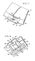
Figure 1 is a perspective view of a lip of an excavating bucket. -
Figure 2 is a perspective view of a lip. -
Figure 3 is top perspective view of a boss. -
Figure 4 is a bottom perspective view of the boss. -
Figure 5 is a side view of the boss. -
Figure 6 is a perspective view of a series of the bosses attached to the lip. -
Figure 7 is an enlarged top perspective view of one of the bosses attached to the lip. -
Figure 8 is an enlarged bottom perspective view of one of the bosses attached to the lip. -
Figure 9 is a perspective view of a lock with the elastomer omitted. -
Figure 10 is a side view of the lock. -
Figure 11 is a perspective view of the lock and its relation to the lip during use. -
Figure 12 is a side view of the lock and its relation to the lip during use. -
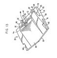
Figure 13 is a top perspective view of a wear member. -
Figure 14 is a bottom perspective view of the wear member. -
Figure 15 is a rear view of the wear member and its relation to the lock during use. -
Figure 16 is a cross-sectional view taken along line XVI-XVI inFigure 1 . -
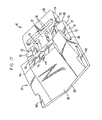
Figure 17 is a top, front perspective view of the wear assembly with the lip omitted. -
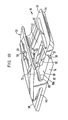
Figure 18 is a rear perspective view of the wear assembly with the lip omitteduse. -
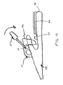
Figure 19 is a side view of the wear member provided with a lifting eye. - In accordance with the present invention, a
wear assembly 10 is provided for attachment along the digging edge of a lip of an excavator. The invention is discussed below in terms of the attachment of a shroud to the lip of a load-haul-dump (LHD) bucket. However, the invention is not limited to the attachment of a shroud or an LHD bucket. The invention could be used to secure other wear members to other excavators, and even to other equipment where the edge is subject to heavy loading and wear as in an excavating environment. - The invention is at times discussed in terms of relative terms, such as up, down, right, left, vertical, horizontal, etc. for the sake of easing the description. These terms are to be considered relative to the orientation of the elements in
Figure 1 (unless otherwise noted), and are not to be considered limitations on the invention. As can be appreciated, the wear member can be used and oriented in a variety of ways. -
Lip 12 forms the front digging edge of an LHD bucket (not shown) to engage and penetrate into the ground for the gathering of earthen material. As seen inFigure 2 ,lip 12 includes a center section ormain member 14 that extends horizontally across the front of the bucket and a pair ofcorner sections 16 generally at right angles to the center section.Corner sections 16 form the lower ends of the front edges of the bucket sidewalls. Each of the lip sections includes aninner face 14a, 16a, anouter face front edge - The
front edges lip sections recesses 18, one for eachwear assembly 10. In the illustrated example, five uniformly spaced scallops are formed alongfront edge 14c, and one scallop in each offront edges 16c. The scallops are each preferably formed to have a uniform, continual,arcuate surface 19 with a curvature that extends no more than about 180 degrees about an axis extending generally perpendicular to the lip, and preferably is at about 180 degrees. In this way,lip 12 withscallops 18 can be easily manufactured, provide a robust base to resist the applied loads, and (as discussed below) provide clearance for the lock ofwear assembly 10 during use. Nevertheless, the scallops could be formed to have a nonuniform curvature, a discontinuous or angular shape, and/or be formed to have partial closure (i.e., a surface with more than a 180 degree extension such that certain side portions of the scallop are opposed to each other). Each of these variations, though, tends to increase the cost of manufacture, lead to more significant stress concentrations, and/or reduced strength. - As shown in
Figure 6 , aboss 20 is fixed tolip 12 over eachscallop 18. Whilebosses 20 are preferably welded to the lip, they could be cast as an integral part of the lip or secured by mechanical means. In addition, the bosses could each be formed as a multiple of parts, which are integral or spaced apart, although a one-piece member is preferred for simplicity and strength. -
Boss 20 has abody 22 extending alongouter face 14b of lip 12 (Figs. 3-5 ).Body 22 preferably includes a pair ofrails 24 extending along sidewalls 26 in a rearward direction fromfront edge sidewall 26 to form a T-shaped configuration.Rails 24 have holdingsurfaces 25 that are spaced from and facingouter face shroud 28 to prevent its movement away from the lip. While a T-shaped configuration is preferred, the rails could have other shapes, such as dovetail. Moreover, for lower stress environments, the rails could be omitted entirely (not shown) so that only thesidewalls 26 defined the sides of the body. - A
brace 30 extends laterally across the rear end ofbody 22. In the preferred construction, the rear ends ofrails 24 are integrally fixed to abrace 30 to additionally support the rails when under load.Brace 30 further extends outward beyond the rails to define astop surface 32 adapted to abut the rear end ofshroud 28 and thereby reduce the stress on the boss, which in turn, reduces the stress alongfront edge lip 12. The use of a brace as an abutment and/or to support the rails has applicability in other arrangements for mounting wear members. -
Brace 30 also preferably has a greater depth thanbody 22 so that it extends from the lip a greater distance than the body to maximize the surface area able to abut the shroud and to function as a deflector for earthen material when the bucket is reversed to reduce reverse loading ofshroud 28. Adeflector face 34 inclined forward fromouter face brace 30 to direct the earthen material away from the assembled boss and shroud.Body 22 andbrace 30 are formed as an open framework, withopenings 36 to reduce the amount of needed steel and to facilitate welding of the boss to the lip. - A
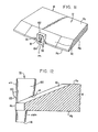
front part 38 ofboss 20 wraps aroundfront edge lip 12 to define afinger portion 39 alonginner face 14a, 16a.Inner surface 40 of boss 20 (i.e., the surface that faces lip 12) is shaped to conform to the shape of the particular lip to which it is fixed. In this case, the inner face includes anupright face 42 to set againstfront edge upper face 44 to set againstramp 46 of inner face 14a. In the preferred construction, the bosses attached to cornersections 16 are the same as those attached to centersection 14. However, other attachments are possible. If the front of the lip had a curved or other shape,inner surface 40 would be changed to match the shape of the lip. Thefront face 48 ofboss 20 preferably has a uniform curved shape, but other shapes are possible. Alternatively,front part 38 could be formed to simply be upturned to abut againstfront edge inner face 14a, 16a. Also,front part 38 could be entirely omitted so thatboss 20 only lies alongouter face body 22 could be fixed toinner face 14a, 16a instead ofouter face - A
recess 50 is formed infinger portion 39. Ahole 52 inbody 22 is aligned withrecess 60 to collectively define apassage 54 for receiving alock 56. In the preferred construction,recess 50 has a generally U-shaped configuration; though other shapes are possible. Themain wall 57 ofrecess 50 is preferably aligned withupright face 42 for bearing against the lock.Hole 52 has amain portion 58 that preferably has a laterally elongated, generally rectangular shape; though other shapes are possible. The shapes ofrecess 50 andhole 52 are largely dependent on the shape of the lock. Whilehole 52 preferably extends throughbody 22, it could have a closed lower end (which would result in the elimination of rib 62). Apocket 60 is defined along a medial section ofmain portion 58 to receive arib 62 ofshroud 28. Agroove 64 is formed infront face 48 and throughfront part 38 to connect withmain portion 58 ofhole 52.Groove 64 is provided to permit the passage ofrib 62 topocket 60 and is thus aligned withpocket 60.Boss 20 is fixed tolip 12 such thatrecess 50 andhole 52 are centrally aligned with one of the scallops 18 (Figs. 7 and 8 ). - In the preferred construction, shrouds 28 have a front working
portion 66 that tapers to a narrowedfront edge 68, and arear mounting portion 70 that is bifurcated to define aninner leg 72 and an outer leg 74 (Figs. 13-18 ).Outer leg 74 has a generally flatouter face 76 and arear deflector face 78 that is inclined forwardly away fromlip 12 to direct any earthen material away from the wear member during reverse movement of the bucket. Theinner face 80 preferably has a pair ofdogleg flanges 82 that face inward to define a T-shapedslot 84 for receivingbody 22 and rails 24.Flanges 82 could vary in shape to define slot with a dovetail or other configurations which complement the shape ofrails 24, or to simply be upright when no rails are provided. Alternatively, the flanges could be replaced with a thicker outer leg that includes inner walls to form the slot receiving theboss 20. Also, the tongue and groove arrangement could be reversed so that the boss was formed to define the slot and the wear member the tongue received into the slot (not shown). -
Shroud 28 includes aninner surface 85 that includesinner face 80 ofouter leg 74,inner face 87 ofinner leg 72, and theinner corner surface 89 at the intersection oflegs 72, 74 (Figs. 13-16 and18 ).Inner corner surface 89 has acentral section 89a that generally matchesfront face 48 ofboss 20 and abuts against it. Accordingly, in the preferred embodiment,inner corner surface 89 has a generally uniform curved surface. When assembled,inner face 80 ofouter leg 74 overliesbody 22 andouter face inner face 87 ofinner leg 72 overliesfinger portion 39 andinner face 14a, 16a (Figs. 16-18 ). Insidecorner surface 89 also includesside sections 89b that have a slightly narrower radius of curvature thancentral section 89a to define side faces 91 that set just outside side surfaces 93 of front part 38 (Figs. 3, 4 and15 ). The juxtaposition of side faces 91 and side surfaces 93 will provide additional lateral support forshroud 28 at the front edge oflip 12. Although all of thebosses 20 are preferably identical, a unique boss could be formed for the center ofcentral section 14 oflip 12 where apeak 100 is formed. In this construction, the inner surface of the boss that wraps around the front edge of the lip would be formed with slight angle to match the formation of the lip.Inner leg 72 includes anaperture 86 adapted to receivelock 56 therein. As a result,aperture 86 is generally aligned withrecess 50,hole 52 and one of thescallops 18. In the preferred embodiment,aperture 86 has a generally rectangular configuration (to match the preferred lock) with therear wall 88 forming bearing faces to abut the lock. As described below,rear wall 88 andfront wall 92 each include acentral groove 94, 96 (Fig. 13 ).Groove 94 is formed to provide clearance for the movement of an elastomer in the lock.Groove 96 is provided to permit the insertion of a pry tool for removing the lock. The rear andfront walls aperture 86 preferably converge toward each other as they extend towardboss 20 to receive a tapered lock that can be pried into and out of the assembly. Arib 62 projects upward frominner face 80 to abut the lower end oflock 56. - When
shroud 28 is installed, it is slid overlip 12 such that inner andouter legs Fig. 1 ).Rails 24 ofbody 22 are fit withinslot 84 asshroud 28 is moved rearward (Fig. 18 ). The rearward movement is continued untilinside corner surface 89 abutsfront face 48 of boss 20 (Figs. 16-18 ). At this juncture,rear wall 98 ofouter leg 74 is preferably placed in close proximity to stopsurface 32. With cast parts, it is not practical forinside conrer surface 89 andrear wall 98 to simultaneously abutfront face 48 and stopsurface 32 , respectively. However, by placingrear wall 98 in close proximity withstop surface 32, the two surfaces will typically abut after a short amount of time as wear develops in the parts. While it is not preferred, stopsurface 32 could be the primary bearing surface that first abutsrear wall 98, withinside corner surface 89 abuttingfront face 48 after some wear. Also, asshroud 28 is installed,rib 62 passes throughgroove 64 infront part 38 ofboss 20, throughmain portion 58 ofhole 52, and intopocket 60. - Once
shroud 28 is fully pushed ontoboss 20,lock 56 is inserted intoaperture 86,recess 50,hole 52 and one of the scallops 18 (Figs. 16-18 ). As seen inFigs. 9-12 , lock 56 preferably has arigid body 102, alatch 104 and an elastomeric member (not shown). In the preferred construction,body 102 has a gradually tapering shape with front andrear walls face 110.Rear wall 108 is divided by astep 112 into an upper orinner section 108a and a lower orouter section 108b. Preferably the inner andouter sections Inner section 108a is adapted to set againstrear wall 88 inaperture 86, andouter section 108b against thefront face 114 ofrib 62. Accordingly,rear wall 88 andfront face 114 are preferably inclined to match the inclination ofrear wall 108. As disclosed in published U.S. Patent ApplicationUS 2003/024139 , entitled "Coupling for Excavating Wear Part," this mating relationship of a tapered lock with the opening into which it is received eases the insertion and removal of the lock; that is, since the lock walls do not fully engage the opening walls until the lock is fully set in the assembly, the necessity for using a large hammer to insert the lock is obviated. Rather, in certain environments, it is possible to manually insert the lock into the assembly without tools. Alternatively, a pry tool may be used. In the example illustrated inFig. 19 , a prying ledge 115 is provided on alifting eye 117. Apry tool 119 can engage prying ledge 115 to pushlock 56 into the assembly. Of course, other prying arrangements are possible, and a hammer could be used if desired. Similarly, since the lock will release from the opening walls immediately after being moved in the release direction, the lock can be pried out of the assembly. - The use of
step 112 permits a larger, more robust portion of the lock to be fit withinaperture 86 and to include acavity 116 to contain the elastomeric material (not shown). The narrower portion belowstep 112 permits the use of ascallop 18 having minimal depth. When assembled,scallop wall 19 is juxtaposed toouter section 108b just below step 112 (Figs. 11-12 ).Rib 62 sets just belowlip 12 so that the inner ortop surface 118 is juxtaposed toouter surface Fig. 16 ). Step 112 generally parallelsramp 46 in a spaced relation (Figs. 11-12 ).Front wall 106 abuts againstmain wall 57 inrecess 50 ofboss 20 andfront wall 120 of hole 52 (Figs. 3 and17-19 ). As can be appreciated, the lock, along bothfront wall 106 andrear wall 108 abutsshroud 28 andboss 20 inside and outside of lip 12 (i.e., to each side of a central plane of themain member 14 orcorner member 16 betweeninner face 14a, 16a andouter face -
Latch 104 is preferably pivotally mounted withincavity 116 of body 102 (Figs. 9-10 ). In particular,latch 104 includes apivot pin 122 that fits within alateral recess 124, astem 126, and ahead 128.Head 128 includes ashoulder 130 that projects outward beyondfront wall 106 to fit underkeeper ledge 59 to retainlock 56 in the wear assembly. An elastomeric material (not shown), such as rubber, is fit withincavity 116 behindlatch 104. The elastomer normally biases latch 104 outward in a locked position, as shown inFigure 10 . The leading orlower surface 132 ofshoulder 130 has a curved configuration to guide the latch rearward as it strikes againstshroud 28 as it is inserted intoaperture 86 so thatshoulder 130 is pushed withincavity 116. When the lock is fully inserted into the assembly, the elastomer biases the latch outward so thatshoulder 130 fits underkeeper ledge 59. In the preferred construction, the elastomer is affixed to the rear wall oflatch 104 and withincavity 116 by adhesive or molding. Alternatively, the elastomer could be held within cavity by friction and/or mechanical means. - To facilitate removal of
lock 56,shroud 28 includesgroove 96 to permit the insertion of a tool (not shown) to push the latch rearward against the bias of the elastomer (Figs. 9 ,13 ,16 and17 ); that is, the tool presses against thefront face 134 ofhead 128 with leverage against thefront wall 136 ofgroove 96.Front wall 136 is curved inward tobetter guide latch 104 rearward, and provide a better leverage surface for the tool.Head 128 preferably also includes apry surface 138 underfront face 134, whereby the tool pushing the latch rearward can be further rotated againstfront wall 136 to pry the lock from the assembly (Figs. 9 and 10 ); that is, the free end of the tool engagespry surface 138 so that as the tool continues to rotate it applies an upward force on the latch. Thepivot pin 122 being received withinrecess 124 provides the needed resistance to permit such prying on the latch. In general, a pry tool (not shown) can be fit intogroove 96 with a pry surface (not shown) to pull the lock from the assembly. -
Shrouds 28 are preferably formed of two different constructions along their sides. As seen inFigures 1 and13-16 , one kind ofshroud 28 includesgrooves 142 which receivetongues 144 from the other kind of shroud 28' (Figure 1 ). In this way, the shrouds mate together, with thetongues 144 ingrooves 142 to provide a more integral assembly and better coverfront edge 14c oflip 12. A third kind ofshroud 28" can be formed withoutgrooves 142 ortongues 144 for attachment to cornersections 16. Nevertheless, a shroud of a single shape of can be used if desired. For instance, each shroud can be formed with a groove on side and a tongue on the other, or each could be formed without either a groove or tongue.
Claims (12)
- A wear assembly comprising:a boss (20) adapted to be fixed to a lip of an excavator, wherein the lip (12) has an inner face (14a), an outer face (14b) and a front edge face (14c), the boss (20) including a opening for receiving a lock (56) therein and a first bearing surface (57) facing generally in a rearward direction;a wear member (28) received over the boss (20) and including an aperture generally aligned with the opening (52) in the boss (20), a second bearing surface (88) and a third bearing surface (114), the second and third bearing surfaces (88, 114) being on opposite sides of a central plane extending medially between the inner and outer faces (14a, 14b) of the lip (12) and each facing in a generally forward direction; anda lock (56) received in the aperture (86) and the opening (52) to be in opposition to the bearing surfaces (57, 88) to hold the wear member to the boss (20;wherein the boss (20) includes a front part (38) that, in use, wraps around the lip (12) and extends partially along one of the inner and outer faces (14a, 14b) and a body (22) that extends along the other of the inner and outer sides (14a, 14b) of the lip (12); characterised by,the wear member (28) including a leg (72, 74) that overlies the body, the leg (72, 74) and the body defining a cooperative tongue and groove construction (24, 84) whereby the leg (72, 74) is held to the lip (12);the boss (20) including a brace (30) having a forwardly facing abutting surface (32), and the leg (72, 74) including a rear wall (98) that is adapted to abut the abutting surface (32).
- A wear assembly in accordance with claim 1 in which the body (22) defines the tongue and the leg defines the groove.
- A wear assembly in accordance with claim 1 in which the body (22) defines the groove and the leg (72, 74) defines the tongue.
- A wear assembly in accordance with claim 1, wherein the body (22) includes sides extending generally away from the front edge face of the lip (12), each side including a rail (24), and each rail (24) including a holding surface spaced from and facing the front member to hold the wear member to the lip.
- A wear assembly in accordance with claim 4, wherein the body with the rails (24) defines a T-shaped configuration.
- A wear assembly in accordance with claim 4, wherein the rails (24) have a dovetail configuration.
- A wear assembly in accordance with claim 4 in which the brace (30) at the rear end of the body extends laterally outward of at least a portion of the body and is fixed to the rails (24).
- A wear assembly in accordance with claim 1 in which the brace (30) extends outward away from the front member farther than the body (22).
- A wear assembly in accordance with claim 1 in which the wear member includes a rib to define the third bearing surface.
- A wear assembly in accordance with claim 9, wherein the boss (20) includes a front surface and a groove that opens in the front surface and extends rearward through a portion of the boss (20), wherein the rib passes through the groove and into the assembly when the wear member is installed on the lip.
- A wear assembly in accordance with claim 1, wherein the lock has front and rear surfaces (106, 108) that are tapered toward a leading end (110), and wherein the opening and the aperture are each tapered in the same direction to receive the lock (56).
- A wear assembly in accordance with claim 11, wherein the lock (56) has a pivotal latch (104) that engages a keeper (59) in the passage to secure the lock (56) in the assembly.
Priority Applications (6)
| Application Number | Priority Date | Filing Date | Title |
|---|---|---|---|
| PL13153874T PL2589715T3 (en) | 2003-04-30 | 2004-04-14 | Lip for an excavating bucket |
| EP13153871.2A EP2589714A3 (en) | 2003-04-30 | 2004-04-14 | Wear assembly for excavator digging edge |
| PL04760540T PL1631725T3 (en) | 2003-04-30 | 2004-04-14 | Wear assembly for excavator digging edge |
| PL13153867T PL2589713T3 (en) | 2003-04-30 | 2004-04-14 | Wear assembly for excavator digging edge |
| EP13153867.0A EP2589713B1 (en) | 2003-04-30 | 2004-04-14 | Wear assembly for excavator digging edge |
| EP13153874.6A EP2589715B1 (en) | 2003-04-30 | 2004-04-14 | Lip for an excavating bucket |
Applications Claiming Priority (2)
| Application Number | Priority Date | Filing Date | Title |
|---|---|---|---|
| US10/425,605 US7080470B2 (en) | 2003-04-30 | 2003-04-30 | Wear assembly for excavator digging edge |
| PCT/US2004/011383 WO2004099512A2 (en) | 2003-04-30 | 2004-04-14 | Wear assembly for excavator digging edge |
Related Child Applications (6)
| Application Number | Title | Priority Date | Filing Date |
|---|---|---|---|
| EP13153867.0A Division EP2589713B1 (en) | 2003-04-30 | 2004-04-14 | Wear assembly for excavator digging edge |
| EP13153871.2A Division EP2589714A3 (en) | 2003-04-30 | 2004-04-14 | Wear assembly for excavator digging edge |
| EP13153874.6A Division EP2589715B1 (en) | 2003-04-30 | 2004-04-14 | Lip for an excavating bucket |
| EP13153871.2 Division-Into | 2013-02-04 | ||
| EP13153874.6 Division-Into | 2013-02-04 | ||
| EP13153867.0 Division-Into | 2013-02-04 |
Publications (3)
| Publication Number | Publication Date |
|---|---|
| EP1631725A2 EP1631725A2 (en) | 2006-03-08 |
| EP1631725A4 EP1631725A4 (en) | 2010-04-21 |
| EP1631725B1 true EP1631725B1 (en) | 2013-06-19 |
Family
ID=33309719
Family Applications (4)
| Application Number | Title | Priority Date | Filing Date |
|---|---|---|---|
| EP13153867.0A Expired - Lifetime EP2589713B1 (en) | 2003-04-30 | 2004-04-14 | Wear assembly for excavator digging edge |
| EP13153874.6A Expired - Lifetime EP2589715B1 (en) | 2003-04-30 | 2004-04-14 | Lip for an excavating bucket |
| EP04760540.7A Expired - Lifetime EP1631725B1 (en) | 2003-04-30 | 2004-04-14 | Wear assembly for excavator digging edge |
| EP13153871.2A Withdrawn EP2589714A3 (en) | 2003-04-30 | 2004-04-14 | Wear assembly for excavator digging edge |
Family Applications Before (2)
| Application Number | Title | Priority Date | Filing Date |
|---|---|---|---|
| EP13153867.0A Expired - Lifetime EP2589713B1 (en) | 2003-04-30 | 2004-04-14 | Wear assembly for excavator digging edge |
| EP13153874.6A Expired - Lifetime EP2589715B1 (en) | 2003-04-30 | 2004-04-14 | Lip for an excavating bucket |
Family Applications After (1)
| Application Number | Title | Priority Date | Filing Date |
|---|---|---|---|
| EP13153871.2A Withdrawn EP2589714A3 (en) | 2003-04-30 | 2004-04-14 | Wear assembly for excavator digging edge |
Country Status (27)
| Country | Link |
|---|---|
| US (2) | US7080470B2 (en) |
| EP (4) | EP2589713B1 (en) |
| JP (1) | JP5005341B2 (en) |
| KR (1) | KR101105975B1 (en) |
| CN (3) | CN100572693C (en) |
| AP (2) | AP2168A (en) |
| AR (2) | AR046803A1 (en) |
| AU (2) | AU2004236654B2 (en) |
| BR (2) | BRPI0419101B1 (en) |
| CA (1) | CA2520002C (en) |
| CL (1) | CL2004000902A1 (en) |
| CO (1) | CO5631465A2 (en) |
| EA (1) | EA007026B1 (en) |
| ES (3) | ES2633213T3 (en) |
| HK (2) | HK1087748A1 (en) |
| HU (1) | HUE036308T2 (en) |
| MX (1) | MXPA05011094A (en) |
| MY (1) | MY138205A (en) |
| NO (1) | NO20055638D0 (en) |
| NZ (2) | NZ553633A (en) |
| OA (1) | OA13122A (en) |
| PE (1) | PE20050380A1 (en) |
| PL (3) | PL2589715T3 (en) |
| SI (1) | SI2589715T1 (en) |
| TW (1) | TWI341892B (en) |
| WO (1) | WO2004099512A2 (en) |
| ZA (1) | ZA200508337B (en) |
Families Citing this family (78)
| Publication number | Priority date | Publication date | Assignee | Title |
|---|---|---|---|---|
| US6729052B2 (en) * | 2001-11-09 | 2004-05-04 | Esco Corporation | Assembly for securing an excavating tooth |
| US7080470B2 (en) * | 2003-04-30 | 2006-07-25 | Esco Corporation | Wear assembly for excavator digging edge |
| US7712234B2 (en) * | 2005-03-30 | 2010-05-11 | Striegel Monte G | Trench wall ripper apparatus |
| US7992328B2 (en) | 2005-03-30 | 2011-08-09 | Striegel Monte G | Trench wall ripper apparatus |
| TWI387675B (en) * | 2005-12-21 | 2013-03-01 | Esco Corp | Wear member,wear assembly and spool for a lock |
| AP2367A (en) | 2006-03-30 | 2012-02-20 | Esco Corp | Wear assembly. |
| US7658024B2 (en) * | 2006-07-06 | 2010-02-09 | H&L Tooth Company | Universal digging tooth attachment apparatus |
| US7526886B2 (en) * | 2006-10-24 | 2009-05-05 | Esco Corporation | Wear assembly for an excavating bucket |
| US20080092412A1 (en) * | 2006-10-24 | 2008-04-24 | Esco Corporation | Wear Assembly For An Excavating Bucket |
| PL2076633T3 (en) | 2006-10-24 | 2017-06-30 | Esco Corporation | Wear assembly for an excavating bucket |
| CA2612341A1 (en) * | 2007-11-27 | 2009-05-27 | Black Cat Blades Ltd. | Ground engaging tool blade |
| DE102009029894B4 (en) * | 2009-06-23 | 2019-03-21 | Betek Gmbh & Co. Kg | Tillage tool |
| NO333294B1 (en) * | 2010-02-17 | 2013-04-29 | Komatsu Kvx Llc | Drawer front mounting device |
| CA2733418C (en) | 2010-03-24 | 2017-05-30 | Boundary Equipment Co. Ltd. | Blade segment and blade assembly for a surface working vehicle |
| WO2011156834A1 (en) * | 2010-06-14 | 2011-12-22 | Sandvik Intellectual Property Ab | Heel shroud and means of mechanical attachment |
| JP2012246735A (en) * | 2011-05-31 | 2012-12-13 | Higuchi Seisakusho Co Ltd | Tooth member and bucket for shovel type excavator |
| US8890672B2 (en) | 2011-08-29 | 2014-11-18 | Harnischfeger Technologies, Inc. | Metal tooth detection and locating |
| WO2013044297A1 (en) * | 2011-09-26 | 2013-04-04 | Bradken Resources Pty Limited | Excavation bucket |
| BR112014012274B1 (en) * | 2011-11-23 | 2021-05-18 | Esco Group Llc | wear member for ground coupling equipment |
| US8959807B2 (en) * | 2011-12-13 | 2015-02-24 | Caterpillar Inc. | Edge protector for ground engaging tool assembly |
| NO334810B1 (en) * | 2012-05-23 | 2014-06-02 | Kverneland Group Operations Norway As | Device for attachment for interchangeable wear part |
| KR102059872B1 (en) * | 2012-06-01 | 2019-12-27 | 에스코 그룹 엘엘씨 | Lip for excavating bucket |
| AP2015008665A0 (en) * | 2013-01-25 | 2015-08-31 | Cqms Pty Ltd | An excavator wear assembly |
| US9359745B2 (en) * | 2013-10-15 | 2016-06-07 | Caterpillar Inc. | Bucket edge protection system |
| US20150191899A1 (en) * | 2014-01-07 | 2015-07-09 | Esco Corporation | Wear member |
| US9758947B2 (en) | 2014-11-07 | 2017-09-12 | Caterpillar Inc. | Mounting base for wear member |
| USD751610S1 (en) | 2014-11-07 | 2016-03-15 | Caterpillar Inc. | Heel shroud |
| USD769945S1 (en) | 2014-12-05 | 2016-10-25 | Caterpillar Inc. | Sidebar protector |
| BR112016022806B1 (en) * | 2015-02-13 | 2022-02-15 | Black Cat Blades Ltd | WEAR MEMBER ATTACHMENT SYSTEM FOR AN EDGE OF AN EXCAVING IMPLEMENT, AND, METHOD FOR PROTECTING AN EDGE OF AN EXCAVING IMPLEMENT |
| US9970181B2 (en) * | 2015-04-17 | 2018-05-15 | Caterpillar Inc. | Lip for machine bucket |
| FR3035889B1 (en) * | 2015-05-05 | 2017-06-16 | Safe Metal | DEVICE, SYSTEM AND METHOD FOR PROTECTING A BUCKET AREE |
| US9611625B2 (en) | 2015-05-22 | 2017-04-04 | Harnischfeger Technologies, Inc. | Industrial machine component detection and performance control |
| US9670648B2 (en) | 2015-08-10 | 2017-06-06 | Caterpillar Inc. | Replaceable tip systems for a tine |
| BR112018005981B1 (en) * | 2015-09-29 | 2022-09-06 | Esco Group Llc | WEAR SET FOR GROUND WORK EQUIPMENT |
| US9695576B2 (en) | 2015-10-30 | 2017-07-04 | Caterpillar Inc. | Wear assembly for loader bucket |
| WO2017083691A1 (en) | 2015-11-12 | 2017-05-18 | Harnischfeger Technologies, Inc. | Methods and systems for detecting heavy machine wear |
| US10119252B2 (en) * | 2015-11-19 | 2018-11-06 | Caterpillar Inc. | Reinforcement system for a tool adapter |
| GB2544794B (en) * | 2015-11-27 | 2018-08-01 | Eastern Attachments Ltd | Loading vehicle attachments |
| USD788826S1 (en) | 2016-02-09 | 2017-06-06 | Caterpillar Inc. | Sidebar protector |
| US10519632B2 (en) | 2016-05-13 | 2019-12-31 | Caterpillar Inc. | Shroud insert assembly using a resilient member |
| US10513837B2 (en) | 2016-05-13 | 2019-12-24 | Caterpillar Inc. | Support assembly for ground engaging tools |
| US10196798B2 (en) | 2016-05-13 | 2019-02-05 | Caterpillar Inc. | Tool adapter and shroud protector for a support assembly for ground engaging tools |
| USD797162S1 (en) * | 2016-07-21 | 2017-09-12 | Caterpillar Inc. | Lip for ground engaging machine implement and/or digital representation thereof |
| USD797163S1 (en) * | 2016-07-21 | 2017-09-12 | Caterpillar Inc. | Lip shroud for ground engaging machine implement and/or digital representation thereof |
| DE102016123662A1 (en) * | 2016-12-07 | 2018-06-07 | Wirtgen Gmbh | Skid segment for edge protection of a road milling machine and edge protection for a road milling machine |
| USD842345S1 (en) | 2017-07-21 | 2019-03-05 | Caterpillar Inc. | Lip shroud for a ground engaging machine implement |
| RU2735207C1 (en) * | 2017-07-27 | 2020-10-28 | Металохения Рисерч Энд Текнолоджиз, С.Л. | Bucket for earthmoving machine cutting edge |
| US11066812B2 (en) | 2017-08-07 | 2021-07-20 | Hensley Industries, Inc. | Bucket lip stabilizer structure |
| USD832309S1 (en) | 2017-08-30 | 2018-10-30 | Caterpillar Inc. | Lip shroud for a ground engaging machine implement |
| USD842346S1 (en) | 2017-10-11 | 2019-03-05 | Caterpillar Inc. | Shroud for a ground engaging machine implement |
| USD842347S1 (en) | 2017-10-11 | 2019-03-05 | Caterpillar Inc. | Shroud for a ground engaging machine implement |
| US10538900B2 (en) * | 2017-11-30 | 2020-01-21 | Caterpillar Inc. | Wear member for a work tool |
| CN108560635A (en) * | 2018-03-07 | 2018-09-21 | 徐工集团工程机械有限公司 | Detachable abrasion protection component and assemble method |
| JP2019163611A (en) * | 2018-03-19 | 2019-09-26 | 越後商事株式会社 | Replaceable edge body for work machine bucket and work machine bucket comprising the replaceable edge body |
| JOP20200249A1 (en) * | 2018-03-30 | 2019-09-30 | Esco Group Llc | Wear member, edge and process of installation |
| US11319692B2 (en) * | 2018-07-16 | 2022-05-03 | Caterpillar Inc. | Ripper shank pocket with wear inserts |
| USD873306S1 (en) | 2018-10-03 | 2020-01-21 | Caterpillar Inc. | Bucket shroud |
| USD882644S1 (en) | 2018-10-03 | 2020-04-28 | Caterpillar Inc. | Bucket shroud |
| USD882645S1 (en) | 2018-10-03 | 2020-04-28 | Caterpillar Inc. | Bucket shroud |
| USD882646S1 (en) | 2018-11-09 | 2020-04-28 | Caterpillar Inc. | Bucket shroud |
| AU2019406813B9 (en) * | 2018-12-20 | 2024-03-28 | Esco Group Llc | Wear member and wear assembly |
| USD905765S1 (en) | 2019-03-07 | 2020-12-22 | Caterpillar Inc. | Adapter for a ground engaging machine implement |
| USD894970S1 (en) | 2019-04-24 | 2020-09-01 | Caterpillar Inc. | Adapter for a ground engaging machine implement |
| US11142894B2 (en) | 2019-04-24 | 2021-10-12 | Caterpillar Inc. | Tip and adapter assembly using a spring steel sleeve design |
| US11124951B2 (en) | 2019-04-24 | 2021-09-21 | Caterpillar Inc. | Spring steel sleeve design |
| USD927561S1 (en) | 2019-10-04 | 2021-08-10 | Caterpillar Inc. | Bucket shroud |
| USD928848S1 (en) | 2019-10-04 | 2021-08-24 | Caterpillar Inc. | Bucket shroud |
| USD928849S1 (en) | 2019-10-04 | 2021-08-24 | Caterpillar Inc. | Bucket shroud |
| WO2021183834A1 (en) | 2020-03-11 | 2021-09-16 | Bierwith Robert S | Fasteners and fastener systems |
| US11499298B2 (en) * | 2020-04-29 | 2022-11-15 | Caterpillar Inc. | Corner segment having protrusions on wear zones |
| US11939740B2 (en) * | 2020-11-18 | 2024-03-26 | Caterpillar Inc. | Work implement assembly using adapters, adapter covers, and a notched base edge |
| USD945499S1 (en) | 2020-11-18 | 2022-03-08 | Caterpillar Inc. | Adapter for a ground engaging machine implement |
| USD945498S1 (en) | 2020-11-18 | 2022-03-08 | Caterpillar Inc. | Adapter for a ground engaging machine implement |
| US20220259837A1 (en) * | 2021-02-17 | 2022-08-18 | Black Cat Wear Parts, Ltd. | Heel shroud for material moving implement and associated methods |
| USD959505S1 (en) | 2021-03-25 | 2022-08-02 | Caterpillar Inc. | Bucket shroud |
| US20220381003A1 (en) * | 2021-05-27 | 2022-12-01 | Caterpillar Inc. | Overlapping cutting edge tip system |
| USD978923S1 (en) | 2021-06-03 | 2023-02-21 | Caterpillar Inc. | Bucket shroud |
| US20220403616A1 (en) * | 2021-06-21 | 2022-12-22 | Caterpillar Inc. | Fatigue life optimized modular bucket assembly |
Family Cites Families (77)
| Publication number | Priority date | Publication date | Assignee | Title |
|---|---|---|---|---|
| US1031138A (en) | 1912-01-11 | 1912-07-02 | Edgar Allen American Manganese Steel Company | Cast-metal dipper-body. |
| US1076548A (en) | 1913-02-27 | 1913-10-21 | Cooley Butler | Dipper for steam shovels and dredges. |
| US1503866A (en) * | 1921-05-28 | 1924-08-05 | American Manganese Steel Co | Toothed cutter lip |
| US1485243A (en) * | 1923-03-14 | 1924-02-26 | Edwin T Blake | Means for reenforcing excavator-bucket teeth |
| US1507697A (en) * | 1923-09-22 | 1924-09-09 | American Manganese Steel Co | Dipper |
| US1775984A (en) * | 1928-10-23 | 1930-09-16 | Electric Steel Foundry Co | Dipper-tooth structure |
| US1959847A (en) | 1931-07-31 | 1934-05-22 | Lesher W Van Buskirk | Dipper construction and the like |
| US2113420A (en) * | 1937-07-10 | 1938-04-05 | Electric Steel Foundry Co | Excavating tooth |
| US2896345A (en) * | 1954-07-23 | 1959-07-28 | Electric Steel Foundry Co | Tooth assembly |
| US3160967A (en) | 1963-09-10 | 1964-12-15 | Irvin H Nichols | Removable blade arrangment with recesses therein for receiving support projections |
| US3388488A (en) * | 1965-11-29 | 1968-06-18 | Duplessis Gerard | Bucket and adaptor assembly for digging teeth |
| US3456370A (en) * | 1967-09-21 | 1969-07-22 | Herman Gilbertson | Corner bit assembly for earthmoving blades |
| US3685177A (en) | 1970-08-13 | 1972-08-22 | Esco Corp | Two piece cutting edge |
| US3851413A (en) * | 1971-08-23 | 1974-12-03 | Caterpillar Tractor Co | Quick change cutting edge |
| US3736664A (en) | 1971-10-12 | 1973-06-05 | Caterpillar Tractor Co | Replaceable pinned-on cutting edge |
| DE7304417U (en) * | 1972-03-08 | 1973-05-17 | Aktiebolaget Bofors | Bucket tooth for excavator buckets or the like |
| US3841007A (en) | 1972-11-24 | 1974-10-15 | Caterpillar Tractor Co | Detachable cutting edge and tip adapter for loader buckets |
| US3864853A (en) | 1973-04-27 | 1975-02-11 | Caterpillar Tractor Co | Quick disconnect cutting edge for earthworking implements |
| US3947982A (en) | 1973-12-10 | 1976-04-06 | Tomaso Mantovani | Structure for connecting teeth to the digging edge of a bucket |
| US3896569A (en) * | 1974-04-09 | 1975-07-29 | Marion Power Shovel Co | Earth working implement and tooth assembly therefor |
| US3995384A (en) | 1974-11-25 | 1976-12-07 | John F. Duncan | Edge bit structure for implement blade |
| US3974579A (en) | 1975-02-04 | 1976-08-17 | Caterpillar Tractor Co. | Bucket tooth adapter support and load transfer means |
| US4006544A (en) | 1975-05-12 | 1977-02-08 | Caterpillar Tractor Co. | Replaceable cutting edge assembly |
| USD245780S (en) | 1975-06-19 | 1977-09-13 | Ab Bofors | Combined adapter and cutter edge unit for excavating, digging or bucket loading shovel |
| JPS5238903U (en) * | 1975-09-12 | 1977-03-18 | ||
| CH599403A5 (en) | 1976-04-12 | 1978-05-31 | Zepf Hans Rudolf | |
| US4052803A (en) * | 1976-10-18 | 1977-10-11 | Caterpillar Tractor Co. | Loader bucket cutting edge with recessed bolt studs and method |
| GB1560650A (en) * | 1976-11-30 | 1980-02-06 | Mantovani T | Tooth supports for buckets or the like accessories for earthmoving equipment |
| FR2381137A1 (en) * | 1977-02-18 | 1978-09-15 | Esco Corp | EXCAVATOR TOOTH FOR LOADER BUCKET ON TIRES OR SIMILAR |
| SE408563B (en) | 1977-09-06 | 1979-06-18 | Bofors Ab | CUTTER TEETH SYSTEM |
| US4449309A (en) | 1979-03-05 | 1984-05-22 | Gh Hensley Industries, Inc. | Flat bottom bucket and digging teeth |
| JPS5655062U (en) * | 1979-10-05 | 1981-05-13 | ||
| US4329798A (en) * | 1980-07-29 | 1982-05-18 | Edwards Gerald D | Tooth construction for digging buckets |
| US4457380A (en) | 1981-06-03 | 1984-07-03 | Curry John N | Blades for earth moving machines |
| US4501079A (en) | 1983-08-24 | 1985-02-26 | Esco Corporation | Two piece cutting edge construction |
| US4570365A (en) | 1983-11-23 | 1986-02-18 | Bierwith Robert S | Digging tooth and bucket lip construction |
| DE3611493A1 (en) | 1986-04-05 | 1987-10-15 | Orenstein & Koppel Ag | Digging shovel for excavators |
| US4716667A (en) * | 1986-09-25 | 1988-01-05 | Gh Hensley Industries, Inc. | Excavating tooth and wear cap assembly |
| US5016365A (en) | 1989-06-06 | 1991-05-21 | Gh Hensley Industries, Inc. | Wear parts for excavation apparatus |
| US5052134A (en) | 1989-10-25 | 1991-10-01 | Bierwith Robert S | Tooth mounting apparatus for excavation bucket |
| US5063695A (en) | 1990-02-12 | 1991-11-12 | Esco Corporation | Replaceable wear element and method |
| US5005304A (en) | 1990-02-12 | 1991-04-09 | Esco Corporation | Replaceable wear element |
| US5241765A (en) | 1991-01-17 | 1993-09-07 | Esco Corporation | Lock assembly for wearable structure |
| US5088214A (en) | 1991-01-17 | 1992-02-18 | Esco Corporation | Excavator wear edge |
| US5075986A (en) | 1991-02-08 | 1991-12-31 | H & L Tooth Company | Attachment assembly for excavation teeth |
| CA2124836C (en) * | 1991-12-20 | 1996-11-12 | Brian J. Hutchins | Attachments for excavating bucket |
| US5283965A (en) * | 1992-01-21 | 1994-02-08 | H & L Tooth Company | Attachment assembly for excavation teeth |
| US5396964A (en) | 1992-10-01 | 1995-03-14 | Halliburton Company | Apparatus and method for processing soil in a subterranean earth situs |
| US5412885A (en) | 1993-07-02 | 1995-05-09 | Caterpillar Inc. | Bucket base edge protector assembly |
| US5438774A (en) | 1993-10-06 | 1995-08-08 | Caterpillar Inc. | Mechanically attached adapter |
| US5465512A (en) | 1994-06-28 | 1995-11-14 | Caterpillar Inc. | Implement assembly with a mechanically attached adapter |
| US5564508A (en) | 1995-08-03 | 1996-10-15 | Caterpillar Inc. | Replacable wear runner |
| US5553409A (en) * | 1995-08-22 | 1996-09-10 | Foothills Steel Foundry Ltd. | Shroud anchor system |
| US5634285A (en) | 1995-09-29 | 1997-06-03 | Caterpillar Inc. | Base edge cover for a bucket and apparatus for retaining same |
| US5806216A (en) | 1995-09-29 | 1998-09-15 | Caterpillar Inc. | Base edge cover for a bucket and apparatus for retaining same |
| AU701175B2 (en) * | 1995-10-18 | 1999-01-21 | Mason & Cox Proprietary Limited | Locking clip pin arrangement |
| US5653048A (en) * | 1995-11-06 | 1997-08-05 | Esco Corporation | Wear assembly for a digging edge of an excavator |
| US5718070A (en) * | 1995-11-13 | 1998-02-17 | Gh Hensley Industries, Inc. | Self-adjusting tooth/adapter connection system for material displacement apparatus |
| US5564206A (en) * | 1995-11-13 | 1996-10-15 | Gh Hensley Industries, Inc. | Self-adjusting tooth/adapter connection system for material displacement apparatus |
| CN1204376A (en) * | 1995-12-11 | 1999-01-06 | 埃斯科公司 | Wear member |
| US5713145A (en) | 1996-03-12 | 1998-02-03 | Gh Hensley Industries, Inc. | Wear resistant excavating apparatus |
| US5937549A (en) | 1996-08-08 | 1999-08-17 | Caterpillar Inc. | Wear member attachment system |
| US5852888A (en) | 1996-11-08 | 1998-12-29 | Caterpillar Inc. | Apparatus for protecting a base of a bucket of an earth working machine |
| US6151812A (en) | 1997-10-30 | 2000-11-28 | Bierwith; Robert S. | Bucket assembly with an improved lip |
| US5987787A (en) | 1998-02-11 | 1999-11-23 | Wright Equipment Company (Proprietary) Limited | Ground engaging tool components |
| ES2146541B1 (en) * | 1998-06-08 | 2001-04-01 | Metalogenia Sa | DEVICE FOR THE COUPLING OF EXCAVATOR TEETH. |
| US6047487A (en) * | 1998-07-17 | 2000-04-11 | H&L Tooth Co. | Multipiece excavating tooth assembly |
| US6145224A (en) | 1998-11-06 | 2000-11-14 | Caterpillar Inc. | Ground engaging tools for earthworking implements and retainer therefor |
| US6194080B1 (en) | 1998-12-16 | 2001-02-27 | Caterpillar Inc. | Replaceable wear member |
| US6108950A (en) * | 1999-03-08 | 2000-08-29 | Gh Hensley Industries, Inc. | Self-adjusting tooth/adapter connection system for material displacement apparatus |
| NL1015772C2 (en) * | 2000-07-21 | 2002-01-22 | Ihc Holland Nv | Assembly of a tooth and an adapter for a soil tillage machine, such as a cutter or the like. |
| CA2417718C (en) | 2000-08-04 | 2009-07-28 | Shark Abrasion Systems Pty Ltd | Attachment system |
| US6209238B1 (en) | 2000-09-18 | 2001-04-03 | Gh Hensley Industries, Inc. | Excavating adapter-to-lip connection apparatus with bottom front-accessible disconnection portion |
| FR2815059B1 (en) * | 2000-10-11 | 2003-03-21 | Charles Pasqualini | DEVICE AND METHOD FOR FIXING PROTECTIVE SHIELDS OF BLADES AND SIDE SIDES OF BUCKETS, BUCKETS AND OTHER RECEPTABLES OF PUBLIC WORKS MACHINERY |
| US6393739B1 (en) * | 2001-08-16 | 2002-05-28 | G. H. Hensley Industries, Inc. | Excavating tooth point and adapter apparatus |
| US6729052B2 (en) * | 2001-11-09 | 2004-05-04 | Esco Corporation | Assembly for securing an excavating tooth |
| US7080470B2 (en) * | 2003-04-30 | 2006-07-25 | Esco Corporation | Wear assembly for excavator digging edge |
-
2003
- 2003-04-30 US US10/425,605 patent/US7080470B2/en not_active Expired - Lifetime
-
2004
- 2004-04-14 CN CNB2004800112995A patent/CN100572693C/en not_active Expired - Fee Related
- 2004-04-14 HU HUE13153874A patent/HUE036308T2/en unknown
- 2004-04-14 CN CN2007100037542A patent/CN101003978B/en not_active Expired - Fee Related
- 2004-04-14 WO PCT/US2004/011383 patent/WO2004099512A2/en active Application Filing
- 2004-04-14 BR BRPI0419101A patent/BRPI0419101B1/en not_active IP Right Cessation
- 2004-04-14 NZ NZ553633A patent/NZ553633A/en not_active IP Right Cessation
- 2004-04-14 EP EP13153867.0A patent/EP2589713B1/en not_active Expired - Lifetime
- 2004-04-14 AU AU2004236654A patent/AU2004236654B2/en not_active Ceased
- 2004-04-14 AP AP2007004246A patent/AP2168A/en active
- 2004-04-14 SI SI200432407T patent/SI2589715T1/en unknown
- 2004-04-14 EP EP13153874.6A patent/EP2589715B1/en not_active Expired - Lifetime
- 2004-04-14 MX MXPA05011094A patent/MXPA05011094A/en active IP Right Grant
- 2004-04-14 KR KR1020057020550A patent/KR101105975B1/en not_active IP Right Cessation
- 2004-04-14 PL PL13153874T patent/PL2589715T3/en unknown
- 2004-04-14 BR BRPI0409899-4A patent/BRPI0409899B1/en not_active IP Right Cessation
- 2004-04-14 CA CA002520002A patent/CA2520002C/en not_active Expired - Fee Related
- 2004-04-14 OA OA1200500297A patent/OA13122A/en unknown
- 2004-04-14 EP EP04760540.7A patent/EP1631725B1/en not_active Expired - Lifetime
- 2004-04-14 NZ NZ543099A patent/NZ543099A/en not_active IP Right Cessation
- 2004-04-14 PL PL13153867T patent/PL2589713T3/en unknown
- 2004-04-14 PL PL04760540T patent/PL1631725T3/en unknown
- 2004-04-14 ES ES13153874.6T patent/ES2633213T3/en not_active Expired - Lifetime
- 2004-04-14 ES ES04760540T patent/ES2424993T3/en not_active Expired - Lifetime
- 2004-04-14 EA EA200501706A patent/EA007026B1/en not_active IP Right Cessation
- 2004-04-14 ES ES13153867.0T patent/ES2548557T3/en not_active Expired - Lifetime
- 2004-04-14 JP JP2006509985A patent/JP5005341B2/en not_active Expired - Fee Related
- 2004-04-14 AP AP2005003422A patent/AP2012A/en active
- 2004-04-14 CN CN200910170749XA patent/CN101649630B/en not_active Expired - Fee Related
- 2004-04-14 EP EP13153871.2A patent/EP2589714A3/en not_active Withdrawn
- 2004-04-23 TW TW093111416A patent/TWI341892B/en not_active IP Right Cessation
- 2004-04-28 PE PE2004000420A patent/PE20050380A1/en not_active Application Discontinuation
- 2004-04-28 AR ARP040101444A patent/AR046803A1/en not_active Application Discontinuation
- 2004-04-28 CL CL200400902A patent/CL2004000902A1/en unknown
- 2004-04-28 MY MYPI20041580A patent/MY138205A/en unknown
-
2005
- 2005-08-31 US US11/216,697 patent/US7451558B2/en active Active
- 2005-10-14 ZA ZA200508337A patent/ZA200508337B/en unknown
- 2005-10-27 CO CO05109779A patent/CO5631465A2/en active IP Right Grant
- 2005-11-29 NO NO20055638A patent/NO20055638D0/en not_active Application Discontinuation
-
2006
- 2006-07-17 HK HK06107953.4A patent/HK1087748A1/en not_active IP Right Cessation
-
2007
- 2007-01-17 AR ARP070100205A patent/AR059660A2/en not_active Application Discontinuation
-
2009
- 2009-03-06 AU AU2009200862A patent/AU2009200862B2/en not_active Ceased
-
2010
- 2010-04-15 HK HK10103677.2A patent/HK1135444A1/en not_active IP Right Cessation
Also Published As
Similar Documents
| Publication | Publication Date | Title |
|---|---|---|
| EP1631725B1 (en) | Wear assembly for excavator digging edge | |
| US7874086B2 (en) | Lock assembly for securing a wear member to earth-working equipment | |
| KR101297529B1 (en) | Wear assembly for excavating machines | |
| US4282665A (en) | Excavator tooth assembly | |
| US7526886B2 (en) | Wear assembly for an excavating bucket | |
| EP2902553B1 (en) | Wear assembly | |
| US20030024139A1 (en) | Coupling for excavating wear part | |
| EP2076633B1 (en) | Wear assembly for an excavating bucket | |
| KR20080103079A (en) | Wear assembly | |
| CA2671621A1 (en) | Wear member for excavating equipment | |
| CA2451306C (en) | Coupling for excavating wear part | |
| US20080092412A1 (en) | Wear Assembly For An Excavating Bucket | |
| AU2002320130A1 (en) | Coupling for excavating wear part | |
| CA1134137A (en) | Earthworking implement side plate wear member | |
| AU2013205223B2 (en) | Coupling for excavating wear part | |
| WO2008130360A1 (en) | Lock assembly for securing a wear member to earth-working equipment |
Legal Events
| Date | Code | Title | Description |
|---|---|---|---|
| PUAI | Public reference made under article 153(3) epc to a published international application that has entered the european phase |
Free format text: ORIGINAL CODE: 0009012 |
|
| 17P | Request for examination filed |
Effective date: 20051121 |
|
| AK | Designated contracting states |
Kind code of ref document: A2 Designated state(s): AT BE BG CH CY CZ DE DK EE ES FI FR GB GR HU IE IT LI LU MC NL PL PT RO SE SI SK TR |
|
| DAX | Request for extension of the european patent (deleted) | ||
| RIN1 | Information on inventor provided before grant (corrected) |
Inventor name: JONES, LARREN, F. |
|
| A4 | Supplementary search report drawn up and despatched |
Effective date: 20100323 |
|
| RIC1 | Information provided on ipc code assigned before grant |
Ipc: E02F 9/28 20060101AFI20100317BHEP |
|
| 17Q | First examination report despatched |
Effective date: 20110210 |
|
| GRAP | Despatch of communication of intention to grant a patent |
Free format text: ORIGINAL CODE: EPIDOSNIGR1 |
|
| GRAS | Grant fee paid |
Free format text: ORIGINAL CODE: EPIDOSNIGR3 |
|
| GRAA | (expected) grant |
Free format text: ORIGINAL CODE: 0009210 |
|
| AK | Designated contracting states |
Kind code of ref document: B1 Designated state(s): AT BE BG CH CY CZ DE DK EE ES FI FR GB GR HU IE IT LI LU MC NL PL PT RO SE SI SK TR |
|
| REG | Reference to a national code |
Ref country code: GB Ref legal event code: FG4D |
|
| REG | Reference to a national code |
Ref country code: CH Ref legal event code: EP |
|
| REG | Reference to a national code |
Ref country code: AT Ref legal event code: REF Ref document number: 617740 Country of ref document: AT Kind code of ref document: T Effective date: 20130715 |
|
| REG | Reference to a national code |
Ref country code: IE Ref legal event code: FG4D |
|
| REG | Reference to a national code |
Ref country code: DE Ref legal event code: R096 Ref document number: 602004042484 Country of ref document: DE Effective date: 20130814 |
|
| REG | Reference to a national code |
Ref country code: RO Ref legal event code: EPE |
|
| REG | Reference to a national code |
Ref country code: SE Ref legal event code: TRGR |
|
| REG | Reference to a national code |
Ref country code: ES Ref legal event code: FG2A Ref document number: 2424993 Country of ref document: ES Kind code of ref document: T3 Effective date: 20131010 |
|
| PG25 | Lapsed in a contracting state [announced via postgrant information from national office to epo] |
Ref country code: SI Free format text: LAPSE BECAUSE OF FAILURE TO SUBMIT A TRANSLATION OF THE DESCRIPTION OR TO PAY THE FEE WITHIN THE PRESCRIBED TIME-LIMIT Effective date: 20130619 |
|
| REG | Reference to a national code |
Ref country code: PL Ref legal event code: T3 |
|
| REG | Reference to a national code |
Ref country code: SK Ref legal event code: T3 Ref document number: E 14698 Country of ref document: SK |
|
| REG | Reference to a national code |
Ref country code: GR Ref legal event code: EP Ref document number: 20130401931 Country of ref document: GR Effective date: 20131015 |
|
| REG | Reference to a national code |
Ref country code: NL Ref legal event code: VDEP Effective date: 20130619 |
|
| PG25 | Lapsed in a contracting state [announced via postgrant information from national office to epo] |
Ref country code: PT Free format text: LAPSE BECAUSE OF FAILURE TO SUBMIT A TRANSLATION OF THE DESCRIPTION OR TO PAY THE FEE WITHIN THE PRESCRIBED TIME-LIMIT Effective date: 20131021 Ref country code: CY Free format text: LAPSE BECAUSE OF FAILURE TO SUBMIT A TRANSLATION OF THE DESCRIPTION OR TO PAY THE FEE WITHIN THE PRESCRIBED TIME-LIMIT Effective date: 20130710 Ref country code: EE Free format text: LAPSE BECAUSE OF FAILURE TO SUBMIT A TRANSLATION OF THE DESCRIPTION OR TO PAY THE FEE WITHIN THE PRESCRIBED TIME-LIMIT Effective date: 20130619 Ref country code: BE Free format text: LAPSE BECAUSE OF FAILURE TO SUBMIT A TRANSLATION OF THE DESCRIPTION OR TO PAY THE FEE WITHIN THE PRESCRIBED TIME-LIMIT Effective date: 20130619 |
|
| PG25 | Lapsed in a contracting state [announced via postgrant information from national office to epo] |
Ref country code: NL Free format text: LAPSE BECAUSE OF FAILURE TO SUBMIT A TRANSLATION OF THE DESCRIPTION OR TO PAY THE FEE WITHIN THE PRESCRIBED TIME-LIMIT Effective date: 20130619 |
|
| PG25 | Lapsed in a contracting state [announced via postgrant information from national office to epo] |
Ref country code: CY Free format text: LAPSE BECAUSE OF FAILURE TO SUBMIT A TRANSLATION OF THE DESCRIPTION OR TO PAY THE FEE WITHIN THE PRESCRIBED TIME-LIMIT Effective date: 20130619 |
|
| PLBE | No opposition filed within time limit |
Free format text: ORIGINAL CODE: 0009261 |
|
| STAA | Information on the status of an ep patent application or granted ep patent |
Free format text: STATUS: NO OPPOSITION FILED WITHIN TIME LIMIT |
|
| PG25 | Lapsed in a contracting state [announced via postgrant information from national office to epo] |
Ref country code: DK Free format text: LAPSE BECAUSE OF FAILURE TO SUBMIT A TRANSLATION OF THE DESCRIPTION OR TO PAY THE FEE WITHIN THE PRESCRIBED TIME-LIMIT Effective date: 20130619 |
|
| 26N | No opposition filed |
Effective date: 20140320 |
|
| REG | Reference to a national code |
Ref country code: HU Ref legal event code: AG4A Ref document number: E019158 Country of ref document: HU |
|
| PG25 | Lapsed in a contracting state [announced via postgrant information from national office to epo] |
Ref country code: IT Free format text: LAPSE BECAUSE OF FAILURE TO SUBMIT A TRANSLATION OF THE DESCRIPTION OR TO PAY THE FEE WITHIN THE PRESCRIBED TIME-LIMIT Effective date: 20130619 |
|
| REG | Reference to a national code |
Ref country code: DE Ref legal event code: R097 Ref document number: 602004042484 Country of ref document: DE Effective date: 20140320 |
|
| PG25 | Lapsed in a contracting state [announced via postgrant information from national office to epo] |
Ref country code: LU Free format text: LAPSE BECAUSE OF FAILURE TO SUBMIT A TRANSLATION OF THE DESCRIPTION OR TO PAY THE FEE WITHIN THE PRESCRIBED TIME-LIMIT Effective date: 20140414 Ref country code: MC Free format text: LAPSE BECAUSE OF FAILURE TO SUBMIT A TRANSLATION OF THE DESCRIPTION OR TO PAY THE FEE WITHIN THE PRESCRIBED TIME-LIMIT Effective date: 20130619 |
|
| REG | Reference to a national code |
Ref country code: CH Ref legal event code: PL |
|
| REG | Reference to a national code |
Ref country code: FR Ref legal event code: ST Effective date: 20141231 |
|
| PG25 | Lapsed in a contracting state [announced via postgrant information from national office to epo] |
Ref country code: LI Free format text: LAPSE BECAUSE OF NON-PAYMENT OF DUE FEES Effective date: 20140430 Ref country code: CH Free format text: LAPSE BECAUSE OF NON-PAYMENT OF DUE FEES Effective date: 20140430 |
|
| PG25 | Lapsed in a contracting state [announced via postgrant information from national office to epo] |
Ref country code: FR Free format text: LAPSE BECAUSE OF NON-PAYMENT OF DUE FEES Effective date: 20140430 |
|
| PG25 | Lapsed in a contracting state [announced via postgrant information from national office to epo] |
Ref country code: TR Free format text: LAPSE BECAUSE OF FAILURE TO SUBMIT A TRANSLATION OF THE DESCRIPTION OR TO PAY THE FEE WITHIN THE PRESCRIBED TIME-LIMIT Effective date: 20130619 |
|
| PGFP | Annual fee paid to national office [announced via postgrant information from national office to epo] |
Ref country code: RO Payment date: 20170327 Year of fee payment: 14 |
|
| PGFP | Annual fee paid to national office [announced via postgrant information from national office to epo] |
Ref country code: SK Payment date: 20170320 Year of fee payment: 14 Ref country code: CZ Payment date: 20170327 Year of fee payment: 14 Ref country code: PL Payment date: 20170320 Year of fee payment: 14 |
|
| PGFP | Annual fee paid to national office [announced via postgrant information from national office to epo] |
Ref country code: GR Payment date: 20170427 Year of fee payment: 14 Ref country code: IE Payment date: 20170428 Year of fee payment: 14 Ref country code: DE Payment date: 20170427 Year of fee payment: 14 Ref country code: GB Payment date: 20170427 Year of fee payment: 14 |
|
| PGFP | Annual fee paid to national office [announced via postgrant information from national office to epo] |
Ref country code: FI Payment date: 20170427 Year of fee payment: 14 Ref country code: AT Payment date: 20170321 Year of fee payment: 14 Ref country code: BG Payment date: 20170428 Year of fee payment: 14 Ref country code: ES Payment date: 20170503 Year of fee payment: 14 Ref country code: SE Payment date: 20170427 Year of fee payment: 14 |
|
| PGFP | Annual fee paid to national office [announced via postgrant information from national office to epo] |
Ref country code: HU Payment date: 20170329 Year of fee payment: 14 |
|
| REG | Reference to a national code |
Ref country code: DE Ref legal event code: R119 Ref document number: 602004042484 Country of ref document: DE |
|
| REG | Reference to a national code |
Ref country code: SE Ref legal event code: EUG |
|
| REG | Reference to a national code |
Ref country code: AT Ref legal event code: MM01 Ref document number: 617740 Country of ref document: AT Kind code of ref document: T Effective date: 20180414 |
|
| GBPC | Gb: european patent ceased through non-payment of renewal fee |
Effective date: 20180414 |
|
| REG | Reference to a national code |
Ref country code: SK Ref legal event code: MM4A Ref document number: E 14698 Country of ref document: SK Effective date: 20180414 |
|
| REG | Reference to a national code |
Ref country code: IE Ref legal event code: MM4A |
|
| PG25 | Lapsed in a contracting state [announced via postgrant information from national office to epo] |
Ref country code: SE Free format text: LAPSE BECAUSE OF NON-PAYMENT OF DUE FEES Effective date: 20180415 Ref country code: CZ Free format text: LAPSE BECAUSE OF NON-PAYMENT OF DUE FEES Effective date: 20180414 Ref country code: SK Free format text: LAPSE BECAUSE OF NON-PAYMENT OF DUE FEES Effective date: 20180414 Ref country code: GR Free format text: LAPSE BECAUSE OF NON-PAYMENT OF DUE FEES Effective date: 20181106 Ref country code: AT Free format text: LAPSE BECAUSE OF NON-PAYMENT OF DUE FEES Effective date: 20180414 Ref country code: RO Free format text: LAPSE BECAUSE OF NON-PAYMENT OF DUE FEES Effective date: 20180414 Ref country code: DE Free format text: LAPSE BECAUSE OF NON-PAYMENT OF DUE FEES Effective date: 20181101 Ref country code: HU Free format text: LAPSE BECAUSE OF NON-PAYMENT OF DUE FEES Effective date: 20180415 Ref country code: FI Free format text: LAPSE BECAUSE OF NON-PAYMENT OF DUE FEES Effective date: 20180414 |
|
| PG25 | Lapsed in a contracting state [announced via postgrant information from national office to epo] |
Ref country code: GB Free format text: LAPSE BECAUSE OF NON-PAYMENT OF DUE FEES Effective date: 20180414 |
|
| PG25 | Lapsed in a contracting state [announced via postgrant information from national office to epo] |
Ref country code: IE Free format text: LAPSE BECAUSE OF NON-PAYMENT OF DUE FEES Effective date: 20180414 |
|
| PG25 | Lapsed in a contracting state [announced via postgrant information from national office to epo] |
Ref country code: BG Free format text: LAPSE BECAUSE OF NON-PAYMENT OF DUE FEES Effective date: 20190430 |
|
| REG | Reference to a national code |
Ref country code: ES Ref legal event code: FD2A Effective date: 20190912 |
|
| PG25 | Lapsed in a contracting state [announced via postgrant information from national office to epo] |
Ref country code: ES Free format text: LAPSE BECAUSE OF NON-PAYMENT OF DUE FEES Effective date: 20180415 |
|
| PG25 | Lapsed in a contracting state [announced via postgrant information from national office to epo] |
Ref country code: PL Free format text: LAPSE BECAUSE OF NON-PAYMENT OF DUE FEES Effective date: 20180414 |