BR112016022806B1 - WEAR MEMBER ATTACHMENT SYSTEM FOR AN EDGE OF AN EXCAVING IMPLEMENT, AND, METHOD FOR PROTECTING AN EDGE OF AN EXCAVING IMPLEMENT - Google Patents
WEAR MEMBER ATTACHMENT SYSTEM FOR AN EDGE OF AN EXCAVING IMPLEMENT, AND, METHOD FOR PROTECTING AN EDGE OF AN EXCAVING IMPLEMENT Download PDFInfo
- Publication number
- BR112016022806B1 BR112016022806B1 BR112016022806-5A BR112016022806A BR112016022806B1 BR 112016022806 B1 BR112016022806 B1 BR 112016022806B1 BR 112016022806 A BR112016022806 A BR 112016022806A BR 112016022806 B1 BR112016022806 B1 BR 112016022806B1
- Authority
- BR
- Brazil
- Prior art keywords
- wear member
- adapter
- lip
- wear
- implement
- Prior art date
Links
Images


Classifications
-
- E—FIXED CONSTRUCTIONS
- E02—HYDRAULIC ENGINEERING; FOUNDATIONS; SOIL SHIFTING
- E02F—DREDGING; SOIL-SHIFTING
- E02F9/00—Component parts of dredgers or soil-shifting machines, not restricted to one of the kinds covered by groups E02F3/00 - E02F7/00
- E02F9/28—Small metalwork for digging elements, e.g. teeth scraper bits
- E02F9/2808—Teeth
- E02F9/2816—Mountings therefor
- E02F9/2825—Mountings therefor using adapters
-
- E—FIXED CONSTRUCTIONS
- E02—HYDRAULIC ENGINEERING; FOUNDATIONS; SOIL SHIFTING
- E02F—DREDGING; SOIL-SHIFTING
- E02F9/00—Component parts of dredgers or soil-shifting machines, not restricted to one of the kinds covered by groups E02F3/00 - E02F7/00
- E02F9/28—Small metalwork for digging elements, e.g. teeth scraper bits
- E02F9/2883—Wear elements for buckets or implements in general
Abstract
sistema de afixação de membro de desgaste para um rebordo de um implemento de escavação, e, método para proteger um rebordo de um implemento de escavação. um sistema de afixação de membro de desgaste para um rebordo de implemento de escavação pode incluir um membro de desgaste que protege uma borda do rebordo, um adaptador de membro de desgaste que afixa o membro de desgaste ao rebordo, o adaptador de membro de desgaste sendo preso ao rebordo por um fixador, e o membro de desgaste sendo preso ao adaptador de membro de desgaste por um outro fixador. um método para proteger um rebordo de implemento de escavação pode incluir prender um adaptador de membro de desgaste ao implemento, o adaptador de membro de desgaste incluindo pelo menos um receptáculo, e inserir uma protuberância em um membro de desgaste no receptáculo. um outro sistema pode incluir um membro de desgaste que protege uma borda dianteira de um rebordo, e um adaptador de membro de desgaste que afixa o membro de desgaste ao rebordo entre dois dentes adjacentes. o membro de desgaste pode compreender uma cobertura e o adaptador pode se envolver em torno da borda do rebordo.wear member affixing system to an edge of a digging implement; and, method of securing an edge of a digging implement. a wear member attachment system for an digging implement flange may include a wear member which protects an edge of the flange, a wear member adapter which secures the wear member to the flange, the wear member adapter being secured to the lip by one fastener, and the wear member being secured to the wear member adapter by another fastener. a method of securing an digging implement lip may include attaching a wear member adapter to the implement, the wear member adapter including at least one receptacle, and inserting a protrusion on a wear member in the receptacle. another system may include a wear member that protects a leading edge of a lip, and a wear member adapter that secures the wear member to the lip between two adjacent teeth. the wear member may comprise a cover and the adapter may wrap around the edge of the lip.
Description
[001] Esta descrição refere-se em geral a equipamentos utilizados e às operações executadas em conjunto com escavação e, em um exemplo descrito a seguir, mais particularmente, proporciona melhorias para membros de desgaste em implementos de escavação.[001] This description generally refers to equipment used and operations performed in conjunction with excavation and, in an example described below, more particularly provides improvements for wear members on excavation implements.
[002] Os implementos de escavação podem ser usados para quebrar,transportar, carregar ou, de outra forma, lidar com minério, rochas, solo e outros materiais. Os materiais manipulados por implementos de escavação podem ser abrasivos, ou caso contrário, causam desgaste dos implementos. Por conseguinte, será prontamente apreciado que as melhorias são continuamente necessárias na técnica de proteger implementos de escavação do desgaste.[002] Digging implements can be used to break, haul, load or otherwise handle ore, rocks, soil and other materials. Materials handled by digging implements can be abrasive, or otherwise cause implement wear. Therefore, it will be readily appreciated that improvements are continually needed in the art of protecting digging implements from wear and tear.
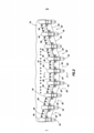
[003] A figura 1 é uma vista em perspectiva representativa de um implemento de escavação que pode beneficiar dos princípios desta descrição.[003] Figure 1 is a representative perspective view of an excavation implement that can benefit from the principles of this description.
[004] A figura 2 é uma vista plana representativa de um sistema de afixação do membro de desgaste que pode incorporar os princípios desta descrição.[004] Figure 2 is a representative plan view of a wear member attachment system that may incorporate the principles of this description.
[005] A figura 3 é uma vista em seção parcialmente transversal representativa em escala ampliada do sistema, tomada ao longo da linha 3-3 da figura 2.[005] Figure 3 is a representative, enlarged-scale, partially cross-sectional view of the system, taken along line 3-3 of figure 2.
[006] A figura 4 é uma vista plana representativa do sistema, com um adaptador do membro de desgaste preso a um rebordo do implemento de escavação.[006] Figure 4 is a representative plan view of the system, with a wear member adapter attached to an edge of the digging implement.
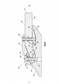
[007] A figura 5 é uma vista em seção parcialmente transversal representativa do sistema, com uma cobertura e uma placa de desgaste sendo posicionados sobre o rebordo e o adaptador do membro de desgaste.[007] Figure 5 is a representative partially cross-sectional view of the system, with a cover and wear plate being positioned over the flange and adapter of the wear member.
[008] A figura 6 é uma vista em seção parcialmente transversal representativa do sistema, com um fixador sendo usado para afixar a cobertura ao adaptador do membro de desgaste.[008] Figure 6 is a representative partially cross-sectional view of the system, with a fastener being used to affix the cover to the wear member adapter.
[009] A figura 7 é uma vista plana representativa do sistema, com a cobertura e a placa de desgaste instaladas.[009] Figure 7 is a representative plan view of the system, with the cover and wear plate installed.
[0010] A figura 8 é uma vista em seção transversal representativa do sistema, tomada ao longo da linha 8-8 da figura 7.[0010] Figure 8 is a representative cross-sectional view of the system, taken along line 8-8 of figure 7.
[0011] Um exemplo de um implemento de escavação 10 é representativamente ilustrado na figura 1 é representativamente ilustrado e pode se beneficiar dos princípios desta descrição. O implemento 10 representado na figura 1 é do tipo conhecido pelos versados na técnica como uma caçamba carregadora de rocha, mas deve ser claramente entendido que o escopo desta descrição não é limitado a qualquer tipo ou configuração particular do implemento de escavação.[0011] An example of a
[0012] No exemplo da figura 1, o implemento 10 inclui um rebordo de fundo geralmente horizontal 12 e dois rebordos laterais geralmente verticais 14. Cada um destes rebordos 12, 14 pode ser submetido a um desgaste devido a operações de escavação. Note-se que os termos descritivos “horizontal”, “fundo”, “vertical” e “lateral” aqui usados para descrever os rebordos 12, 14 são apenas em referência ao implementar 10 como representado na figura 1, e o escopo desta descrição não está limitada para usar com qualquer orientação particular ou local de um rebordo do implemento de escavação.[0012] In the example of figure 1, the
[0013] Os dentes 16 são espaçados ao longo do rebordo de fundo 12. Os dentes 16 são montados no rebordo 12 por meio de respectivos adaptadores de dentes 18. Os adaptadores 18 fornecem a substituição conveniente dos dentes 16. Tipicamente, os adaptadores 18 são soldados ao rebordo 12, e os dentes 16 são anexados aos adaptadores usando fixadores removíveis (não mostrados na figura 1).[0013] The
[0014] Entre os pares adjacentes dos dentes 16 e os adaptadores 18, as aberturas 20 se estendem através do rebordo 12. As aberturas 20 fornecem montar coberturas de montagem de coberturas (não mostrado na figura 1) no rebordo 12 entre os pares adjacentes dos dentes 16 e os adaptadores 18.[0014] Between adjacent pairs of
[0015] As coberturas protegem pelo menos um lado de fundo do rebordo 12 de dano e desgaste. As coberturas também podem servir para outras finalidades, tais como para fornecer relativamente corte através do fundo do implemento 10 (que, por sua vez, deixa uma superfície consistente relativamente lisa cortada pelo implemento). As coberturas também podem ser fornecidas para proteger os rebordos laterais 14 de dano e desgaste.[0015] Covers protect at least one bottom side of
[0016] Infelizmente, as últimas configurações de cobertura têm contado com a afixação das coberturas diretamente no implemento 10 usando múltiplos fixadores. Foi reconhecido que uma tal afixação direta de coberturas pode ser inconveniente, na medida em que requer a remoção e a instalação dos múltiplos fixadores, bem como de quaisquer outros membros de desgaste anexados aos fixadores, a fim de substituir as coberturas. Os fixadores são tipicamente parafusos e porcas convencionais, que podem ser difíceis de remover com sucesso após o implemento 10 ser usado para operações de escavação longas o suficiente para requerer a substituição das coberturas.[0016] Unfortunately, recent cover configurations have relied on attaching covers directly to implement 10 using multiple fasteners. It has been recognized that such direct affixing of covers can be inconvenient as it requires the removal and installation of multiple fasteners, as well as any other wear members attached to the fasteners, in order to replace the covers. Fasteners are typically conventional bolts and nuts, which can be difficult to remove successfully after implement 10 has been used for digging operations long enough to require replacement of covers.
[0017] Referindo-se adicionalmente agora à figura 2, sistemas de afixação do membro de desgaste 22 são representativamente ilustrados e um método associado que pode incorporar os princípios desta descrição. No entanto, deve ser claramente entendido que os sistemas 22 e o método são meramente um exemplo de uma aplicação dos princípios desta descrição, na prática, e uma grande variedade de outros exemplos são possíveis. Portanto, o escopo desta descrição não é limitado a todos os detalhes do sistema 22 e do método aqui descritos e/ou representados nos desenhos.[0017] Referring now further to Figure 2 , wear
[0018] Cada sistema 22 é usado para afixar um membro de desgaste 24 a um rebordo do implemento de escavação. No exemplo da figura 2, os membros de desgaste 24 compreendem coberturas, e os sistemas 22 são usados para afixar os membros de desgaste 24 ao rebordo de fundo 12 do implemento 10 da figura 1. No entanto, deve ser entendido que os sistemas 22 podem ser usados para afixar outros tipos de membros de desgaste, e os sistemas podem ser usados para afixar membros de desgaste a outros rebordos (tais como os rebordos laterais 14) e outros implementos de escavação, em acordo com os princípios desta descrição.[0018] Each
[0019] Como representado na figura 2, cada um dos sistemas 22 é posicionado entre um par adjacente dos dentes 16 e os adaptadores dos dentes 18. Desta forma, os membros de desgaste 24 podem proteger o rebordo 12 do desgaste entre cada par de adaptadores de dentes 18 que estão mais próximos uns dos outros.[0019] As shown in Figure 2, each of the
[0020] No entanto, o escopo desta descrição não é limitado ao uso dos sistemas 22, entre pares adjacentes dos dentes 16 ou os adaptadores dos dentes 18. Em alguns exemplos, um sistema 22 não pode ser posicionado entre um par de dentes ou adaptadores dos dentes. Em um exemplo, o sistema 22 pode ser usado nos rebordos laterais 14, caso em que o sistema não seria posicionado entre os dentes ou os adaptadores dos dentes.[0020] However, the scope of this description is not limited to the use of
[0021] No exemplo da figura 2, o membro de desgaste 24 protege uma aresta dianteira 26 e uma superfície de fundo 28 do rebordo 12 (não visível na figura 2, ver Figs. 3-8). Um membro de desgaste separado 30 é fornecido neste exemplo para proteger uma superfície superior 32 do rebordo 12.[0021] In the example of Figure 2, the
[0022] No entanto, em outros exemplos, o membro de desgaste 30 pode não ser usado, ou pode ser combinado com o membro de desgaste 24. Assim, o escopo desta descrição não é limitado ao uso de quaisquer localizações particulares, número, configurações ou combinações de membros de desgaste no sistema 22.[0022] However, in other examples, the
[0023] Referindo-se adicionalmente agora à figura 3, uma vista parcialmente em seção transversal do sistema 24 e do rebordo 12 é ilustrada de forma representativa, tomada ao longo da linha 3-3 da figura 2. Nesta vista, um adaptador do membro de desgaste 34 está sendo posicionado sobre o rebordo 12. O adaptador do membro de desgaste 34 proporciona anexação conveniente e segura do membro de desgaste 24 ao rebordo 12, e proporciona facilidade de remoção do membro de desgaste a partir do rebordo.[0023] Referring further now to Figure 3, a partially cross-sectional view of the
[0024] Neste exemplo, o adaptador 34 envolve a aresta dianteira 26 do rebordo 12. Esta configuração permite o volume de material suficiente no adaptador 34 estender uma abertura que recebe o fixador 36 através de uma extremidade dianteira do adaptador para anexar o membro de desgaste 24 ao adaptador. No entanto, não é necessário para o adaptador 34 envolver a aresta dianteira 26 do rebordo 12, ou para a abertura que recebe o fixador 36 a ser formada na extremidade dianteira do adaptador, em conformidade com os princípios desta descrição.[0024] In this example, the
[0025] Os fixadores 38 (dos quais apenas um é visível na figura 3) são usados para prender o adaptador 34 ao rebordo 12. Neste exemplo, o fixador 38 inclui um parafuso com rosca e porca, mas outros tipos de fixadores podem ser usados em outros exemplos.[0025] Fasteners 38 (only one of which is visible in Figure 3) are used to secure
[0026] A porca é recebida em uma porção radialmente alargada 20a da abertura 20. O parafuso pode se estender para cima a partir da porca e se projetar a partir da superfície superior 32 do rebordo 12, a fim de proporcionar afixação do membro de desgaste 30, se desejado (ver figura 5-8 e a descrição que acompanha abaixo).[0026] The nut is received in a radially widened
[0027] O adaptador 34 inclui um ou mais receptáculos 40 para receber no seu interior uma ou mais saliências 42 (não mostrado na figura 3, ver a figura 5) formadas no membro de desgaste 24. Cada receptáculo 40 inclui uma superfície inclinada 44 que desvia o membro de desgaste 24 na direção do rebordo 12 quando o membro de desgaste é instalado sobre o adaptador 34, retendo assim uma porção traseira do membro de desgaste.[0027] The
[0028] A superfície inclinada 44 pode ser uma de várias superfícies inclinadas 44, 46, 48 no adaptador 34 que são paralelas umas às outras. As superfícies paralelas 44, 46, 48 engatam correspondentes superfícies paralelas 50, 52, 54 formadas sobre o membro de desgaste 24 (ver a figura 5), quando o membro de desgaste está afixado ao adaptador 34. Este engate entre as superfícies paralelas 44, 46, 48 e 50, 52, 54 permite que o membro de desgaste 24 seja mais facilmente deslocado para baixo e para a frente em relação ao rebordo 12 quando o membro de desgaste estiver sendo substituído.[0028] The
[0029] Referindo-se adicionalmente agora à figura 4, uma vista plana do sistema 24 é ilustrada de forma representativa, após o adaptador 34 ser preso ao rebordo 12. Note-se que cinco dos fixadores 38 estão representados na figura 4, mas qualquer número de fixadores pode ser usado de acordo com os princípios desta descrição.[0029] Referring further now to Figure 4, a plan view of the
[0030] Note que uma rosca interna 56 está associada com cada uma das aberturas de recepção do fixador 36. A rosca 56 é excêntrica em relação à sua abertura associada, para uso com um fixador de uma configuração especial, como descrito mais completamente abaixo.[0030] Note that an
[0031] Referindo-se adicionalmente agora à figura 5, o sistema 22 é ilustrado de forma representativa como os membros de desgaste 24, 30 estão sendo anexados ao adaptador 34 e o rebordo 12. Os fixadores 38 são usados para afixar o membro de desgaste 30, de modo que se sobreponham à superfície superior 32 do rebordo 12. O membro de desgaste 24 é instalado no adaptador 34, de modo que as superfícies 44, 46, 48 sejam engatadas com as respectivas superfícies 50, 52, 54, e de modo que uma extremidade dianteira do adaptador seja recebida em um rebaixo 58 formado no membro de desgaste.[0031] Referring further now to Figure 5, the
[0032] Referindo-se adicionalmente agora à figura 6, o sistema 22 é representativamente ilustrado, após o membro de desgaste 30 ter sido afixado à superfície superior 32 do rebordo 12, e o membro de desgaste 24 foi engatado com o adaptador 34. O membro de desgaste 24 é agora preso ao adaptador 34 por meio de um fixador especialmente configurado 60.[0032] Referring further now to Figure 6, the
[0033] O fixador 60 tem um corpo geralmente cilíndrico 62, com uma rosca excentricamente formada 64 (a rosca não está centrada em relação a um eixo longitudinal 66 do corpo 62). Um fixador semelhante, usado para afixar um dente de um dente do adaptador, é descrito na patente US no. 8261472, do qual a descrição completa é aqui incorporada por esta referência.[0033]
[0034] Note que o fixador 60, quando instalado no membro de desgaste 24 e no adaptador 34, é orientado ortogonal ao rebordo 12. Isto é, um eixo longitudinal 66 do fixador 60 é perpendicular às superfícies superior e inferior 28, 32 do rebordo 12. Esta orientação proporciona para a instalação e a remoção do fixador 60 convenientes, com o membro de desgaste 24 e o adaptador 34 sendo posicionados entre um par adjacente dos dentes 16 e os adaptadores dos dentes 18. No entanto, outras orientações do fixador 60 podem ser usadas em outros exemplos, de acordo com os princípios desta descrição.[0034] Note that
[0035] Referindo-se adicionalmente agora à figura 7, o sistema 22 é representativamente ilustrado com os membros de desgaste 24, 30 afixados ao rebordo 12 e ao adaptador 34. Nesta configuração, o membro de desgaste/a cobertura 24 protege a aresta dianteira 26 e a superfície de fundo 28 do rebordo 12, e o membro de desgaste/placa de desgaste 30 protege a superfície superior 32 do rebordo.[0035] Referring further now to Figure 7, the
[0036] Referindo-se adicionalmente agora à figura 8, uma vista em seção transversal do sistema 22 é ilustrada representativamente, tomada ao longo da linha 8-8 da figura 7. Nesta vista, um dispositivo de travamento 68 que engata a rosca 64 do fixador 60 e, assim, impede que o desenroscar do fixador possa ser visto. A aresta dianteira 26, a superfície de fundo 28 e a superfície superior 32 do rebordo 12 são agora protegidas de dano e desgaste pelos membros de desgaste 24, 30.[0036] Referring further now to Figure 8, a cross-sectional view of the
[0037] Pode ser agora devidamente apreciado que a descrição acima proporciona avanços significativos para a técnica de prevenir o desgaste dos implementos de escavação. Nos exemplos acima descritos, o membro de desgaste 24 é convenientemente anexável a, e removível do(s), rebordo 12 (e/ou rebordos 14) por meio do adaptador do membro de desgaste 34.[0037] It can now be properly appreciated that the above description provides significant advances to the technique of preventing wear and tear on digging implements. In the examples described above, wear
[0038] Um sistema de afixação do membro de desgaste 22 para um rebordo 12, 14 de um implemento de escavação 10 é fornecido com a técnica pela descrição acima. Em um exemplo, o sistema 22 pode incluir um membro de desgaste 24 que protege uma aresta dianteira 26 do rebordo 12, e um adaptador do membro de desgaste 34 que proporciona a afixação do membro de desgaste 24 ao rebordo 12. O adaptador do membro de desgaste 34 é preso ao rebordo 12, por um ou mais primeiros fixadores 38, e o membro de desgaste 24 é preso ao adaptador do membro de desgaste 34 por um ou mais segundos fixadores 60.[0038] A
[0039] O segundo fixador 60 pode incluir uma rosca 64 que é excêntrica em relação a um corpo 62 do segundo fixador. O segundo fixador 60 pode ser orientado ortogonal em relação ao rebordo 12.[0039] The
[0040] O adaptador do membro de desgaste 34 pode ser posicionado entre dois adaptadores de dentes 18 mais próximos uns dos outros no rebordo 12. O adaptador do membro de desgaste 34 pode ser posicionado entre o rebordo 12 e o membro de desgaste 24, tal como, entre o membro de desgaste e uma superfície de fundo 28 do rebordo, ou entre o membro de desgaste e uma aresta dianteira 26 do rebordo.[0040]
[0041] O membro de desgaste 24 pode compreender uma cobertura. A cobertura 24 pode ser posicionada entre dois dentes adjacentes 16, a cobertura sendo atrás dos dentes.[0041] The
[0042] O adaptador do membro de desgaste 34 pode incluir pelo menos um receptáculo 40. O membro de desgaste 24 pode incluir pelo menos uma saliência 42 recebida no receptáculo 40.[0042]
[0043] As superfícies paralelas 50, 52, 54 sobre o membro de desgaste 24 podem ser engatadas com as superfícies paralelas 44, 46, 48 no adaptador do membro de desgaste 34. Pelo menos uma das superfícies paralelas do membro de desgaste 50, 52, 54 pode ser formada sobre a saliência 42, e pelo menos uma das superfícies paralelas do adaptador do membro de desgaste 44, 46, 48 podem ser formadas no receptáculo 40. As superfícies paralelas do membro de desgaste 50, 52, 54 e as superfícies paralelas do adaptador do membro de desgaste 44, 46,48 podem ser inclinadas em relação ao rebordo 12.[0043] The parallel surfaces 50, 52, 54 on the
[0044] Um método de proteção de um rebordo 12, 14 de um implemento de escavação 10 também é provido para a técnica pela descrição acima. Em um exemplo, o método pode compreender: prender um adaptador do membro de desgaste 34 ao implemento 10, o adaptador do membro de desgaste 34, incluindo pelo menos um receptáculo 40; e engatar um membro de desgaste 24 com o adaptador do membro de desgaste 34, a etapa de engate compreendendo a inserção de pelo menos uma saliência 42 sobre o membro de desgaste 24 no receptáculo 40.[0044] A method of protecting an
[0045] A etapa de preensão pode incluir a extensão de fixadores 38 através do rebordo 12 e do adaptador do membro de desgaste 34.[0045] The gripping step may include extending
[0046] A etapa de preensão pode incluir o posicionamento do adaptador do membro de desgaste 34 entre dois adaptadores de dentes 18 que são mais próximos um do outro sobre o rebordo 12.[0046] The gripping step may include positioning the
[0047] A etapa de preensão pode incluir o adaptador do membro de desgaste 34 sobrepondo uma aresta dianteira 26 do rebordo 12. Note que não é necessário de acordo com os princípios desta descrição para o adaptador do membro de desgaste 34 ou para o membro de desgaste 24 sobreporem ou envolverem a aresta dianteira 26 do rebordo 12.[0047] The gripping step may include the
[0048] O método pode incluir a fixação do membro de desgaste 24 ao adaptador do membro de desgaste 34 com pelo menos um fixador 60. O fixador 60 pode ser orientado ortogonal ao rebordo 12. O fixador 60 pode incluir uma rosca 64 que é excêntrica em relação a um corpo 62 do fixador.[0048] The method may include attaching
[0049] A etapa de engate pode incluir o posicionamento do adaptador do membro de desgaste 34 entre o membro de desgaste 24 e o rebordo 12, tal como, entre o membro de desgaste e uma superfície de fundo 28 do rebordo, ou entre o membro de desgaste e uma aresta dianteira 26 do rebordo.[0049] The step of engaging may include positioning the
[0050] A etapa de engate pode incluir engatar superfícies paralelas 50, 52, 54 no membro de desgaste 24 com superfícies paralelas 44, 46, 48 no adaptador do membro de desgaste 34.[0050] The step of engaging may include engaging
[0051] Também é descrito acima um sistema de afixação do membro de desgaste 22 por um rebordo 12, 14 de um implemento de escavação dianteira 26 do rebordo 12, e um adaptador do membro de desgaste 34 que fornece afixação do membro de desgaste 24 ao rebordo 12. O adaptador do membro de desgaste 34 é fixado ao rebordo 12 entre dois dentes adjacentes 16. O adaptador do membro de desgaste 34 pode também ser fixado ao rebordo 12 entre dois adaptadores de dentes adjacentes 18.[0051] Also described above is a system for attaching
[0052] Uma cobertura (por exemplo, membro de desgaste 24), para proteger um rebordo 12, 14 de um implemento de escavação 10, é também descrita acima. Em um exemplo, a cobertura pode incluir um corpo 70 que envolve a aresta dianteira 26 do rebordo 12, e uma saliência 42 que se estende do corpo 70 e para dentro de um receptáculo 40 em um adaptador do membro de desgaste 34 preso ao rebordo 12. Uma superfície 50 sobre a saliência 42 engata em uma superfície 44 no receptáculo 40, a superfície do receptáculo 44 voltada pelo menos parcialmente para a frente e sendo inclinada em relação ao rebordo 12. O engate entre a superfície da saliência 50 e a superfície do receptáculo 44 desvia o corpo 70 na direção do rebordo 12.[0052] A cover (e.g. wear member 24) for protecting a
[0053] A superfície do receptáculo 44 pode ser uma de várias superfícies paralelas 44, 46, 48 formadas no adaptador do membro de desgaste 34. A superfície da saliência 50 pode ser uma de várias superfícies paralelas 50, 52, 54 formadas na cobertura.[0053] The surface of the
[0054] Embora vários exemplos tenham sido descritos acima, com cada exemplo tendo determinados aspectos, deve ser entendido que não é necessário para um aspecto particular de um exemplo a ser usado exclusivamente com esse exemplo. Em vez disso, qualquer dos aspectos descritos acima e/ou representados nos desenhos podem ser combinados com qualquer um dos exemplos, para além de ou em substituição de qualquer dos outros aspectos desses exemplos. Uma das características não é mutuamente exclusiva para outros do exemplo. Em vez disso, o escopo desta descrição engloba qualquer combinação de qualquer um dos aspectos.[0054] While several examples have been described above, with each example having certain aspects, it should be understood that it is not necessary for a particular aspect of an example to be used exclusively with that example. Rather, any of the aspects described above and/or depicted in the drawings may be combined with any of the examples, in addition to or in lieu of any of the other aspects of those examples. One of the characteristics is not mutually exclusive to others in the example. Rather, the scope of this description encompasses any combination of any of the aspects.
[0055] Embora cada exemplo descrito acima inclua uma determinada combinação de aspectos, deve ser entendido que não são necessários todos os aspectos de um exemplo a ser usado. Em vez disso, qualquer aspecto descrito acima pode ser usado, sem qualquer outro aspecto particular ou aspectos também sendo usados.[0055] While each example described above includes a certain combination of aspects, it should be understood that not all aspects of an example are required to be used. Instead, any aspect described above may be used, without any other particular aspect or aspects also being used.
[0056] Deve ser entendido que as várias formas de realização aqui descritas podem ser usadas em várias orientações, tais como inclinadas, invertidas, horizontais, verticais, etc., e em várias configurações, sem se afastar dos princípios desta descrição. As formas de realização são descritas meramente como exemplos de aplicações úteis dos princípios desta descrição, que não se limitam aos detalhes específicos destas formas de realização.[0056] It should be understood that the various embodiments described herein may be used in various orientations, such as tilted, inverted, horizontal, vertical, etc., and in various configurations, without departing from the principles of this description. The embodiments are described merely as examples of useful applications of the principles of this description, which are not limited to the specific details of these embodiments.
[0057] Na descrição acima dos exemplos representativos, os termos direcionais (tais como “acima”, “abaixo”, “superior”, “inferior”, etc.) são usados por conveniência referindo-se aos desenhos anexos. No entanto, deve ser claramente entendido que o escopo desta descrição não é limitado a quaisquer direções particulares aqui descritas.[0057] In the above description of representative examples, directional terms (such as "above", "below", "upper", "lower", etc.) are used for convenience with reference to the accompanying drawings. However, it should be clearly understood that the scope of this description is not limited to any particular directions described herein.
[0058] Os termos “incluindo”, “inclui”, “compreendendo”, “compreende”, e termos semelhantes são usados em um sentido não limitativo, nesta descrição. Por exemplo, se um sistema, método, aparelho, dispositivo, etc., é descrito como “incluindo” uma determinada característica ou elemento, o sistema, o método, aparelho, dispositivo, etc., que podem incluir aspecto ou elemento, e também pode incluir outros aspectos ou elementos. Da mesma forma, o termo "compreende" é considerado para significar “compreende, mas não está limitado a”.[0058] The terms "including", "includes", "comprising", "comprises", and similar terms are used in a non-limiting sense in this specification. For example, if a system, method, apparatus, device, etc., is described as "including" a particular feature or element, the system, method, apparatus, device, etc., may include an aspect or element, and also may include other aspects or elements. Likewise, the term "comprises" is taken to mean "comprises, but is not limited to".
[0059] Naturalmente, um versado na técnica, após uma cuidadosa consideração da descrição acima de formas de realização representativas da descrição, prontamente aprecia que muitas modificações, adições, substituições, eliminações, e outras alterações podem ser feitas às formas de realização específicas, e tais modificações são contempladas pelos princípios desta descrição. Por exemplo, as estruturas descritas como sendo formadas separadamente podem, em outros exemplos, ser integralmente formadas e vice-versa. Por conseguinte, a descrição detalhada anterior é para ser claramente entendida como sendo dada a título de ilustração e somente exemplo, o espírito e escopo da invenção sendo limitados somente pelas reivindicações anexas e seus equivalentes.[0059] Of course, one skilled in the art, after careful consideration of the above description of representative embodiments of the description, will readily appreciate that many modifications, additions, substitutions, deletions, and other changes can be made to specific embodiments, and such modifications are contemplated by the principles of this description. For example, structures described as being separately formed may, in other examples, be integrally formed and vice versa. Accordingly, the foregoing detailed description is to be clearly understood as being given by way of illustration and example only, the spirit and scope of the invention being limited only by the appended claims and their equivalents.
Claims (15)
Applications Claiming Priority (1)
| Application Number | Priority Date | Filing Date | Title |
|---|---|---|---|
| PCT/US2015/015739 WO2016130135A1 (en) | 2015-02-13 | 2015-02-13 | Wear members for excavation implements |
Publications (2)
| Publication Number | Publication Date |
|---|---|
| BR112016022806A2 BR112016022806A2 (en) | 2017-08-15 |
| BR112016022806B1 true BR112016022806B1 (en) | 2022-02-15 |
Family
ID=56615427
Family Applications (2)
| Application Number | Title | Priority Date | Filing Date |
|---|---|---|---|
| BR112016022806-5A BR112016022806B1 (en) | 2015-02-13 | 2015-02-13 | WEAR MEMBER ATTACHMENT SYSTEM FOR AN EDGE OF AN EXCAVING IMPLEMENT, AND, METHOD FOR PROTECTING AN EDGE OF AN EXCAVING IMPLEMENT |
| BR122017028277-8A BR122017028277B1 (en) | 2015-02-13 | 2015-02-13 | Cover to protect an edge of a digging implement |
Family Applications After (1)
| Application Number | Title | Priority Date | Filing Date |
|---|---|---|---|
| BR122017028277-8A BR122017028277B1 (en) | 2015-02-13 | 2015-02-13 | Cover to protect an edge of a digging implement |
Country Status (13)
| Country | Link |
|---|---|
| US (1) | US9963857B2 (en) |
| EP (1) | EP3122948B1 (en) |
| JP (1) | JP6454780B2 (en) |
| KR (1) | KR101945606B1 (en) |
| CN (1) | CN106232909B (en) |
| AR (1) | AR103661A1 (en) |
| AU (1) | AU2015382413B2 (en) |
| BR (2) | BR112016022806B1 (en) |
| CA (2) | CA2943615C (en) |
| ES (1) | ES2900338T3 (en) |
| MX (1) | MX359297B (en) |
| WO (1) | WO2016130135A1 (en) |
| ZA (1) | ZA201606746B (en) |
Families Citing this family (15)
| Publication number | Priority date | Publication date | Assignee | Title |
|---|---|---|---|---|
| BR112016022806B1 (en) * | 2015-02-13 | 2022-02-15 | Black Cat Blades Ltd | WEAR MEMBER ATTACHMENT SYSTEM FOR AN EDGE OF AN EXCAVING IMPLEMENT, AND, METHOD FOR PROTECTING AN EDGE OF AN EXCAVING IMPLEMENT |
| CA2985772A1 (en) | 2016-11-18 | 2018-05-18 | Harnischfeger Technologies, Inc. | Modular ground engagement tooling system |
| CN106592681A (en) * | 2017-03-01 | 2017-04-26 | 江苏洛克精密铸造有限公司 | Novel bucket tooth |
| US11066812B2 (en) | 2017-08-07 | 2021-07-20 | Hensley Industries, Inc. | Bucket lip stabilizer structure |
| JOP20200249A1 (en) * | 2018-03-30 | 2019-09-30 | Esco Group Llc | Wear member, edge and process of installation |
| US11078644B2 (en) * | 2018-04-11 | 2021-08-03 | Deere & Company | Hybrid load bucket assembly |
| JP6486537B1 (en) * | 2018-07-28 | 2019-03-20 | 生企工営株式会社 | Bucket tip cover |
| USD905764S1 (en) | 2019-03-07 | 2020-12-22 | Caterpillar Inc. | Adapter cover for a ground engaging machine implement |
| USD905763S1 (en) * | 2019-03-07 | 2020-12-22 | Caterpillar Inc. | Adapter cover for a ground engaging machine implement |
| US20220268001A1 (en) * | 2019-07-24 | 2022-08-25 | 2Mt Mining Products Pty Ltd | Protection systems |
| US11634892B2 (en) | 2019-11-27 | 2023-04-25 | Hensley Industries, Inc. | Excavating tooth assembly with releasable lock pin assembly |
| USD945500S1 (en) | 2020-11-18 | 2022-03-08 | Caterpillar Inc. | Adapter cover for a ground engaging machine implement |
| USD983234S1 (en) | 2020-11-18 | 2023-04-11 | Caterpillar Inc. | Adapter cover for a ground engaging machine implement |
| EP4015710A1 (en) * | 2020-12-18 | 2022-06-22 | Sandvik Mining and Construction Australia (Production/Supply) Pty Ltd. | Corner half arrow for a bucket |
| CN117769618A (en) * | 2022-04-11 | 2024-03-26 | 汉斯莱产业股份有限公司 | Lip for use on material displacement apparatus |
Family Cites Families (50)
| Publication number | Priority date | Publication date | Assignee | Title |
|---|---|---|---|---|
| US1003663A (en) * | 1911-02-23 | 1911-09-19 | John Gifford Skelton | Dipper-tooth. |
| US3851413A (en) * | 1971-08-23 | 1974-12-03 | Caterpillar Tractor Co | Quick change cutting edge |
| US3736664A (en) * | 1971-10-12 | 1973-06-05 | Caterpillar Tractor Co | Replaceable pinned-on cutting edge |
| IT1027392B (en) * | 1975-01-28 | 1978-11-20 | Ramella P V | TOOTH FOR BUCKETS OF EARTH MOVING MACHINES |
| US6735890B2 (en) * | 2001-07-06 | 2004-05-18 | Esco Corporation | Wear assembly |
| US4180926A (en) * | 1978-02-03 | 1980-01-01 | Caterpillar Tractor Co. | Load absorbing means for cutting edge assembly |
| SE445125B (en) * | 1981-03-26 | 1986-06-02 | Bofors Ab | SOIL WORKING MACHINERY SYSTEM |
| US4716667A (en) * | 1986-09-25 | 1988-01-05 | Gh Hensley Industries, Inc. | Excavating tooth and wear cap assembly |
| US5016365A (en) * | 1989-06-06 | 1991-05-21 | Gh Hensley Industries, Inc. | Wear parts for excavation apparatus |
| US5088214A (en) * | 1991-01-17 | 1992-02-18 | Esco Corporation | Excavator wear edge |
| US5063696A (en) * | 1991-02-13 | 1991-11-12 | Atlantic Richfield Company | Excavator bucket tooth retention device |
| US5553409A (en) * | 1995-08-22 | 1996-09-10 | Foothills Steel Foundry Ltd. | Shroud anchor system |
| US5634285A (en) * | 1995-09-29 | 1997-06-03 | Caterpillar Inc. | Base edge cover for a bucket and apparatus for retaining same |
| US5718070A (en) | 1995-11-13 | 1998-02-17 | Gh Hensley Industries, Inc. | Self-adjusting tooth/adapter connection system for material displacement apparatus |
| US5937550A (en) | 1995-12-11 | 1999-08-17 | Esco Corporation | Extensible lock |
| US5666748A (en) * | 1995-12-11 | 1997-09-16 | Esco Corporation | Wear cap and components useable therewith |
| US5765301A (en) | 1996-08-05 | 1998-06-16 | H&L Tooth Company | Retention apparatus for a ground engaging tool |
| US5909962A (en) | 1997-11-26 | 1999-06-08 | Caterpillar Inc. | Tip assembly for an edge of an implement of a work machine |
| US6145224A (en) * | 1998-11-06 | 2000-11-14 | Caterpillar Inc. | Ground engaging tools for earthworking implements and retainer therefor |
| US6108950A (en) | 1999-03-08 | 2000-08-29 | Gh Hensley Industries, Inc. | Self-adjusting tooth/adapter connection system for material displacement apparatus |
| US6439796B1 (en) | 2000-08-02 | 2002-08-27 | Gh Hensley Industries, Inc. | Connector pin apparatus and associated methods |
| US20020120406A1 (en) | 2001-02-01 | 2002-08-29 | Avraham Lorber | Diagnostic method and apparatus |
| US6430851B1 (en) | 2001-04-10 | 2002-08-13 | H&L Tooth Co. | Hammerless attachment assembly for a two-part digging tooth system |
| US6668472B2 (en) | 2001-07-16 | 2003-12-30 | Robert Bierwith | Wedge-locking system and excavation bucket assembly with wedge-locking system |
| US6393739B1 (en) | 2001-08-16 | 2002-05-28 | G. H. Hensley Industries, Inc. | Excavating tooth point and adapter apparatus |
| US6729052B2 (en) * | 2001-11-09 | 2004-05-04 | Esco Corporation | Assembly for securing an excavating tooth |
| US6708431B2 (en) | 2001-12-03 | 2004-03-23 | Hensley Industries, Inc. | Excavating tooth assembly with rotatable connector pin structure |
| DE60333502D1 (en) | 2002-09-19 | 2010-09-02 | Esco Corp | Wear arrangement and lock for an excavator bucket. |
| US20040098886A1 (en) * | 2002-11-26 | 2004-05-27 | Hohmann Robert A. | Base edge protection system |
| US7080470B2 (en) * | 2003-04-30 | 2006-07-25 | Esco Corporation | Wear assembly for excavator digging edge |
| US20050132619A1 (en) * | 2003-12-23 | 2005-06-23 | Robinson Howard W. | Excavating lip-mounted adapter and associated connection and shielding apparatus |
| ITUD20040021A1 (en) * | 2004-02-10 | 2004-05-10 | Italricambi Srl | TOOTH FOR EXCAVATOR BUCKETS OR SIMILAR |
| CA2555794C (en) * | 2004-03-30 | 2012-09-25 | Metalogenia, S.A. | Device for removably fixing two mechanical parts to one another |
| US20050229442A1 (en) * | 2004-03-30 | 2005-10-20 | Esco Corporation | Wear edge assembly |
| US7526886B2 (en) | 2006-10-24 | 2009-05-05 | Esco Corporation | Wear assembly for an excavating bucket |
| CA2663881C (en) * | 2006-10-24 | 2012-08-07 | Esco Corporation | Wear assembly for an excavating bucket |
| ATE467726T1 (en) * | 2007-06-01 | 2010-05-15 | Ihc Holland Ie Bv | DENTAL SYSTEM |
| US7788830B2 (en) * | 2008-02-08 | 2010-09-07 | Cqms Razer (Usa) Llc | Excavation retention assembly |
| MX344454B (en) | 2009-03-23 | 2016-12-16 | Black Cat Blades Ltd | Fully stabilized excavator tooth attachment. |
| US7980011B2 (en) * | 2009-03-23 | 2011-07-19 | Black Cat Blades Ltd. | Fully stabilized excavator tooth attachment |
| US8261472B2 (en) * | 2009-03-23 | 2012-09-11 | Black Cat Blades Ltd. | Retrofitted excavator tooth attachment |
| WO2011069212A1 (en) * | 2009-12-11 | 2011-06-16 | Cqms Pty Ltd | A wear member assembly |
| JO3763B1 (en) * | 2010-04-20 | 2021-01-31 | Esco Group Llc | Coupling assemblies with enhanced take up |
| BR112014019862A8 (en) * | 2012-02-17 | 2017-07-11 | Esco Corp | WEAR COMPONENT FOR EARTH REMOVAL EQUIPMENT |
| US9447564B2 (en) * | 2013-06-10 | 2016-09-20 | Caterpillar Inc. | Wear member |
| US9404240B2 (en) * | 2013-11-07 | 2016-08-02 | Caterpillar Inc. | Bucket lip protection assemblies and lip adapters for same |
| US9903101B2 (en) * | 2014-12-05 | 2018-02-27 | Caterpillar Inc. | Replaceable shroud for work implement |
| BR112016022806B1 (en) * | 2015-02-13 | 2022-02-15 | Black Cat Blades Ltd | WEAR MEMBER ATTACHMENT SYSTEM FOR AN EDGE OF AN EXCAVING IMPLEMENT, AND, METHOD FOR PROTECTING AN EDGE OF AN EXCAVING IMPLEMENT |
| US9644348B2 (en) * | 2015-08-12 | 2017-05-09 | Caterpillar Inc. | Ground engaging tooth assemblies |
| US10273663B2 (en) * | 2015-08-24 | 2019-04-30 | Caterpillar Inc. | Shroud collar for edge protection of a work tool |
-
2015
- 2015-02-13 BR BR112016022806-5A patent/BR112016022806B1/en active IP Right Grant
- 2015-02-13 AU AU2015382413A patent/AU2015382413B2/en active Active
- 2015-02-13 WO PCT/US2015/015739 patent/WO2016130135A1/en active Application Filing
- 2015-02-13 BR BR122017028277-8A patent/BR122017028277B1/en active IP Right Grant
- 2015-02-13 CN CN201580020904.3A patent/CN106232909B/en active Active
- 2015-02-13 ES ES15882220T patent/ES2900338T3/en active Active
- 2015-02-13 CA CA2943615A patent/CA2943615C/en active Active
- 2015-02-13 MX MX2016013073A patent/MX359297B/en active IP Right Grant
- 2015-02-13 CA CA3001369A patent/CA3001369C/en active Active
- 2015-02-13 JP JP2017507673A patent/JP6454780B2/en active Active
- 2015-02-13 EP EP15882220.5A patent/EP3122948B1/en active Active
- 2015-02-13 KR KR1020167032118A patent/KR101945606B1/en active IP Right Grant
- 2015-12-09 US US14/963,442 patent/US9963857B2/en active Active
-
2016
- 2016-02-11 AR ARP160100373A patent/AR103661A1/en active IP Right Grant
- 2016-09-29 ZA ZA2016/06746A patent/ZA201606746B/en unknown
Also Published As
| Publication number | Publication date |
|---|---|
| BR122017028277B1 (en) | 2022-05-10 |
| CA2943615A1 (en) | 2016-08-18 |
| KR101945606B1 (en) | 2019-02-07 |
| CA3001369C (en) | 2019-07-02 |
| AU2015382413A1 (en) | 2016-10-13 |
| ZA201606746B (en) | 2019-04-24 |
| BR112016022806A2 (en) | 2017-08-15 |
| CA2943615C (en) | 2018-06-05 |
| CN106232909B (en) | 2020-03-17 |
| CA3001369A1 (en) | 2016-08-18 |
| AR103661A1 (en) | 2017-05-24 |
| EP3122948B1 (en) | 2021-10-13 |
| AU2015382413B2 (en) | 2017-03-30 |
| MX2016013073A (en) | 2017-02-14 |
| ES2900338T3 (en) | 2022-03-16 |
| US9963857B2 (en) | 2018-05-08 |
| JP2017514049A (en) | 2017-06-01 |
| MX359297B (en) | 2018-09-24 |
| JP6454780B2 (en) | 2019-01-16 |
| US20160237658A1 (en) | 2016-08-18 |
| EP3122948A4 (en) | 2017-12-20 |
| EP3122948A1 (en) | 2017-02-01 |
| KR20160143843A (en) | 2016-12-14 |
| CN106232909A (en) | 2016-12-14 |
| WO2016130135A1 (en) | 2016-08-18 |
Similar Documents
| Publication | Publication Date | Title |
|---|---|---|
| BR112016022806B1 (en) | WEAR MEMBER ATTACHMENT SYSTEM FOR AN EDGE OF AN EXCAVING IMPLEMENT, AND, METHOD FOR PROTECTING AN EDGE OF AN EXCAVING IMPLEMENT | |
| ES2905218T3 (en) | System to retain a wear element in a bucket | |
| ES2902642T3 (en) | Machinery Wear Set | |
| US8561326B2 (en) | Protective wear assembly for material handling apparatus | |
| ES2896349T3 (en) | Attachment of the wear member to the shoulder of the digging implement | |
| BR102016016627A2 (en) | wear member retention system for an implement | |
| BR112020009011A2 (en) | wear parts for earthmoving equipment | |
| ES2851344T3 (en) | Device, system and procedure for protecting a blade edge | |
| US9409258B2 (en) | Wear member stabilization on excavator lip | |
| US20240011255A1 (en) | Wear component stabilization for material handling implement | |
| BR112015026611B1 (en) | WEAR MEMBER STABILIZATION SYSTEM AND METHOD |
Legal Events
| Date | Code | Title | Description |
|---|---|---|---|
| B06U | Preliminary requirement: requests with searches performed by other patent offices: procedure suspended [chapter 6.21 patent gazette] | ||
| B11B | Dismissal acc. art. 36, par 1 of ipl - no reply within 90 days to fullfil the necessary requirements | ||
| B11N | Dismissal: publication cancelled [chapter 11.14 patent gazette] |
Free format text: ANULADA A PUBLICACAO CODIGO 11.2 NA RPI NO 2605 DE 08/12/2020 POR TER SIDO INDEVIDA. |
|
| B11B | Dismissal acc. art. 36, par 1 of ipl - no reply within 90 days to fullfil the necessary requirements | ||
| B11N | Dismissal: publication cancelled [chapter 11.14 patent gazette] |
Free format text: ANULADA A PUBLICACAO CODIGO 11.2 NA RPI NO 2609 DE 05/01/2021 POR TER SIDO INDEVIDA. |
|
| B350 | Update of information on the portal [chapter 15.35 patent gazette] | ||
| B09A | Decision: intention to grant [chapter 9.1 patent gazette] | ||
| B09X | Republication of the decision to grant [chapter 9.1.3 patent gazette] | ||
| B16A | Patent or certificate of addition of invention granted [chapter 16.1 patent gazette] |
Free format text: PRAZO DE VALIDADE: 20 (VINTE) ANOS CONTADOS A PARTIR DE 13/02/2015, OBSERVADAS AS CONDICOES LEGAIS. |