EP1631142B2 - Procédé et dispositif pour traire un animal - Google Patents
Procédé et dispositif pour traire un animal Download PDFInfo
- Publication number
- EP1631142B2 EP1631142B2 EP04739661.9A EP04739661A EP1631142B2 EP 1631142 B2 EP1631142 B2 EP 1631142B2 EP 04739661 A EP04739661 A EP 04739661A EP 1631142 B2 EP1631142 B2 EP 1631142B2
- Authority
- EP
- European Patent Office
- Prior art keywords
- pressure
- valve
- pulsator
- phase
- milking
- Prior art date
- Legal status (The legal status is an assumption and is not a legal conclusion. Google has not performed a legal analysis and makes no representation as to the accuracy of the status listed.)
- Not-in-force
Links
Images


Classifications
-
- A—HUMAN NECESSITIES
- A01—AGRICULTURE; FORESTRY; ANIMAL HUSBANDRY; HUNTING; TRAPPING; FISHING
- A01J—MANUFACTURE OF DAIRY PRODUCTS
- A01J5/00—Milking machines or devices
- A01J5/007—Monitoring milking processes; Control or regulation of milking machines
Definitions
- the object of the invention relates to a method for the automatic milking of an animal, for example a cow, in which a pulsating negative pressure with successive evacuation phases and ventilation phases is generated in a teat cup via an associated pulsator, as well as on a pulsator.
- a pulsating negative pressure with successive evacuation phases and ventilation phases is generated in a teat cup via an associated pulsator, as well as on a pulsator.
- a substantially uniformly pulsating negative pressure is generated in the pulse space of a milking cup in order to set a teat cup provided in the teat space in the interior of the milking cup into a pulsating milking movement.
- the vacuum device of a Saugmelkstrom comprises a vacuum pump, a vacuum valve, pressure connection lines to the teat cups and a control device for generating valve control pulses.
- a valve opening pulse and valve closing pulse is generated.
- the vacuum pump of the system generates a substantially constant negative pressure, which corresponds approximately to the pulsation pressure.
- control device At fixed predetermined time intervals, the control device generates control signals for opening the valve of the vacuum device, so that a negative pressure is built up substantially abruptly in the teat cup space. This vacuum will maintained over a fixed period of time. As in the case of vacuum build-up, after receiving a further control pulse, the pressure in the milking-chamber gap is suddenly reduced by evacuating the pulse space again. Within a preset pulsation period, this process is repeated evenly.
- the pressure variation in the phase transitions is influenced in such a way that a slower pressure build-up or underpressure build-up is made possible and an improved compatibility achieved by making the phase transitions flatter.
- the problems arising due to sudden movements of the teatcup liner during vacuum or vacuum removal can thus be avoided.
- the existing pulsator valve is used by short-term driving with opening or closing pulses to flatten the pressure curve.
- a disadvantage of shallower pressure changes is the overall longer duration of a pulse cycle.
- Another disadvantage is the decreasing milking speed.
- a teatcup liner is set in motion in a teat cup by a suction vacuum via adjustable pulsation phases with alternating suction phases and relief phases and a pulsation intensity in order to achieve a milk flow.
- the milk volume flow is recorded continuously, whereby the teat rubber movement is selectively changed with a decreasing volume flow.
- the patent US 5,970,910 describes a milking method and associated MelkVorraum, in which for the preservation of the teats of an animal to be milked while reducing the residual milk quantity a ventilation operation for setting a normal pressure and / or an evacuation process for adjusting a negative pressure of a pulsation chamber in a teat cup is carried out in each case with different pressure gradients.
- the pressure gradient is changed when the instantaneous pressure reaches a predeterminable average pressure between the lowest pressure and the normal air pressure that can be generated by a pump in the device.
- the present invention is based on the object of specifying a method and a device by means of which a more gentle milking of an animal at an acceptable speed is made possible.
- a pulsating negative pressure is generated in a pulse space of a milking cup by changing the negative pressure in the pulse space in the pressure change phases.
- the pressure profile is controlled during at least one pressure change phase via an adjustment of an actuating unit in at least two speeds.
- the method is characterized in that the time course of the evacuation phase and / or the ventilation phase is adjusted in dependence on a valve characteristic of a valve having at least two valve openings of the pulsator, wherein the valve cross-section of the valve of the pulsator is changed to change the speed during the pressure change phase.
- a change in pressure phase can be understood to mean the evacuation phase and / or also the ventilation phase of a pulsator cycle.
- the pressure curve is the speed of a pressure change over time. Faster pressure changes produce steeper pressure gradients than slower pressure changes with flatter pressure gradients.
- the process control according to the invention has many advantages. Due to the two speeds, with which a pressure change can be effected, on the one hand a sufficiently fast milking can be achieved while, on the other hand, the teat is gently treated.
- the ventilation phase can be divided into two sections. In the first section, the pressure build-up can then take place at a lower speed than in the second section.
- the pulsating negative pressure is adjusted via a pulsator, wherein the pressure profile during the pressure change phase (s) is preferably controlled by means of an adjustment of an actuating device.
- the actuator may e.g. electrically or mechanically controlled and it can change a mechanical manipulated variable, such. a flow cross-section.
- the aeration phase is referred to as the period in which the vacuum level drops from the highest value in the pulse space to a predetermined lowest vacuum value.
- the invention is based on the basic idea that the time course of the evacuation phase and / or the aeration phase is set by means of two pressure change rates.
- the respective period required by a pressure change phase is only marginally longer than in the prior art. At a correspondingly greater ventilation speed after applying the teatcup liner to the teat, which is then harmless, the period can remain the same length.
- the course of the pressure drop or pressure increase has an effect on the speed of movement of the teatcup liner.
- a corresponding opening and / or closing speed of the teatcup liner is achieved.
- B a correlation produced, which is used in an advantageous manner for the milking process.
- the pressure profile is controlled at least during the venting phase in order to prevent the teatcup from hitting the teat.
- the pressure profile can also be controlled at least during the evacuation phase.
- the rate of pressure change within a period of time is substantially continuous. It can also be provided more than two time periods and / or more than two speeds of pressure change, for each three. Then, the pressure can be changed faster first, until about the folding pressure of the teatcup liner is reached, then slower until the teatcup liner has been gently closed or opened, then again close faster or open.
- the time profile of at least one pressure change phase namely the evacuation phase and / or the ventilation phase is discontinuous at least within a section.
- the pressure profile in a first section and in a following section of the aeration phase is controlled such that the pressure profile in the first section is flatter than in the following section, and particularly preferably considerably flatter.
- the pressure in the pulse space is then increased to about the folding-in pressure.
- the teatcup liner slowly settles and an unpleasant beating on the teat is significantly reduced or even prevented. Thereafter, the pressure build-up is faster and the pressure curve is steeper.
- the pressure profile in a first section and in a subsequent section of the evacuation phase is controlled such that the pressure profile in the first section is flatter than in the following section, and preferably considerably shallower.
- the pressure is reduced until the pressure difference between the pulse chamber and the teat chamber corresponds approximately to the folding-in pressure, and is preferably somewhat smaller, so that the teatcup liner has lifted off. Thereafter, the speed of the pressure change is increased and the pressure curve becomes steeper, to ensure a quicker progression after the slow lift off. This prevents the so-called and unwanted back-spraying of milk on the teat.
- three sections are possible, wherein in a first and third section, the speed is high and in the second section in a pressure range in the vicinity of the fold-in speed is reduced.
- the rate of pressure change is lower and then faster after the teatcup liner has been applied to the teat.
- the switchover pressure is preferably approximately the respective fold-in pressure of the teatcup liner, that is to say the pressure at which the pressure difference between the pulse and teat chambers corresponds approximately to the fold-in pressure of the teatcup liner.
- the predetermined one Switching pressure is preferably adjustable.
- aeration phase it is preferable that, at a pressure difference, slightly larger than a folding pressure is switched from the lower pressure changing speed to a high pressure changing speed to prevent high-speed folding of the teatcup liner.
- the evacuation phase it is preferable that, at a pressure difference, slightly larger than a folding pressure is switched from the low pressure changing speed to a high pressure changing speed to prevent opening of the teatcup liner at a high speed.
- the method according to the invention makes it possible to adapt pulsators to a milking cup, a milking machine or several connected milking devices, organic milking devices, different tube lengths and cross sections, as well as volumes in the milking cup and milking cluster.
- the quality of the pulsation can thus also be controlled by software.
- an electronically tracked control of pulsation quality it is thus also possible to control the dynamic progress of the evacuation phase or the aeration phase.
- the duration of the evacuation phase and / or the aeration phase is set.
- the course of the pressure change during the duration of the evacuation phase and / or the aeration phase can be different. It is also possible to adjust the course according to the technical and / or physiological conditions of the plant or the animal within the specified duration.
- the method according to the invention can also be carried out in conjunction with modern control devices or control systems in the form of, for example, a herd management system. If such a control system has animal-specific data and if it is known which animal is to undergo milking, the course of the evacuation phase can take place and / or the ventilation phase are also set animal-specific. In particular, the speeds may be predetermined or customized.
- the different speeds of the pressure curve can be selected depending on the fold-in pressure of the teatcup liner intended for milking.
- the area of the phase relevant to the opening of the teatcup liner should be designed such that the resulting increase in volume within the teat cup does not result in a backspray effect in the direction of the teat.
- the time period responsible for the opening can be designed specifically.
- a first part of the flow cross-section are opened in the pulsator and later another part. This results in a variable speed of movement.
- Pulsators are known which have a different system structure.
- the purpose of a pulsator is to direct air of higher or lower pressure to the milking cup (s) via the pulsation tubes, which is used in conjunction with the vacuum applied to the tip of the teat and the atmospheric outside air to produce movement of the teatcup liner.
- the pulsator has at least one valve.
- the flow resistance is changed to the milking cup.
- the free flow cross section, in particular in the pulse tube, is changed is preferred.
- valve cross-section of a valve of the pulsator is changed in order to influence the speed during a pressure change phase.
- the valve cross section or the free flow cross section of a valve can do this be changed in several stages.
- the valve cross section can also be changed continuously by sliding a slide or the like over the valve openings or increasing the free flow cross section during the movement.
- a change of the cross-section takes place monotonically and particularly preferably strictly monotonically in the mathematical sense.
- the change takes place over a large part of the duration of the pressure change phase.
- the valve cross section may e.g. be changed over 25% or 50% of the time span.
- the duration of the change is then e.g. 35, 50 or 70 or even more milliseconds.
- the ratio of the two stages is preferably in the range between 1: 4 and 4: 1, more preferably between 1: 2 and 2: 1.
- the length of a section at two speed levels is about half the duration of the respective pressure change phase.
- the pulsator valve is held in at least a portion of a pressure change phase in a floating position by appropriate control pulses are applied to the valve.
- the floating control is basically as known from the prior art.
- the pulsator valve is held in a variable float position in at least a portion of a pressure change phase.
- a variable-time floating position is also preferred in which the opening cross-section is increased or decreased with increasing time.
- the pressure in the pulse space is detected and preferably forms an input signal of a structural unit, which supplies an output signal, by which the pulsator and / or a flow resistance is actuated.
- the pressure change speed is changed only in the movement periods of the teatcup liner so that the speed of movement of the teatcup liner is reduced and after the teatcup liner has closed is controlled to a larger, preferably maximum, rate of pressure change so that the actual pressure change phases remain the same length, as in the prior art. A shortening of the pressure change phases is possible.
- the evacuation phase of the pulsation is preferably subdivided into at least two regions, wherein the pressure drop per unit of time is designed differently.
- the maximum pressure drop is thus selected as a function of the folding pressure of the milking teatcup liner.
- a pulsator for a milking device for milking an animal, for example a cow, for alternately connecting a vacuum source and a pressure source with at least one teat cup is proposed.
- a device is provided by means of which at least the temporal pressure variation during at least one pressure change phase can be controlled in at least two speeds.
- the pulsator according to the invention is characterized in that it has at least one valve with at least two valve openings and the time profile of the at least one pressure change phase in response to a valve characteristic of the valve is adjustable, wherein the valve cross-section of the valve of the pulsator is variable to the speed during to change the pressure change phase.
- the movement of a teatcup liner can be changed or varied in an advantageous manner.
- the mechanical conditions on the milking device such as, for example, can also be adjusted.
- the preload, material and geometry of the teatcup liner are taken into account.
- the vacuum level can also be found in the course of the evacuation phase and / or the ventilation phase.
- the teatcup liner is made of an elastic material.
- the movement of the teatcup liner and the aging process can lead to a change in the movement of the teatcup liner over time. If the behavior of the teatcup liner is known, for example, as a function of the number of movements performed, this behavior can be taken into consideration as an input when it comes to setting the course of the evacuation phase and / or the ventilation phase.
- the device has at least one timing element, by means of which at least the duration of the evacuation phase and / or the ventilation phase can be set. It is also possible to adapt the behavior of the pulsator to the animal to be milked, if it is known which animal is currently undergoing a milking process. In this case, animal-specific data from a herd management system can be used to specify the course of the evacuation phases and / or the ventilation phases. There is also the possibility that for each animal or groups of animals specific courses of Pulsations horres be deposited. These courses are then queried when the relevant animal or group of animals is or will undergo a milking process. The variation or adjustability of the evacuation phase and / or the aeration phase can take place not only during a milking process but also during a stimulation process. In this case, different courses for a stimulation process or for a milking process can be used.
- Pulsatorventil whose opening cross-section is variable. This can be variable continuously or discontinuously. It is also possible that the opening cross-section is variable in several stages.
- the pulsator or the pulsator valve may have a pilot valve and a main valve.
- a design as a direct valve is also preferred.
- the valve has at least two valve openings whose opening cross-section is variable.
- the openings can be designed as bores. Likewise, non-circular cross sections are possible.
- the valve openings may have different cross sections.
- the pulsator according to the invention may have two openings, one of which is larger and one smaller.
- a first opening for a high rate of pressure change then has e.g. 3 mm or 5 mm in diameter, while a smaller one has a diameter of only 1 mm for slower pressure changes.
- the diameter of the opening of the conventional pulsator is a compromise between speed and load of the teat.
- the means of the pulsator may comprise an element which is a nozzle or orifice.
- the opening diameters are variable by e.g. corresponding panels are replaced.
- the pulsator advantageously comprises a valve closing element, which cooperates with the valve openings.
- the adjustment of the free flow cross-section is effected by an interaction of valve openings and valve closing element in the form of, for example, a sliding element in a sliding seat valve.
- the valve of the device With the valve of the device, the time course of the evacuation phase and / or the aeration phase in dependence on a valve characteristic of the valve can be adjusted.
- the valve may be, for example, a directly actuated sliding seat valve or else a pilot valve of a pulsator, which is specifically guided on a valve characteristic.
- the main valve of the pulsator receives its control from the pilot valve.
- the main valve follows the pilot valve in an analogous manner and delivers pressures to the pulsation line in accordance with its valve characteristic.
- the valve characteristic of the pilot valve and the characteristic of the main valve can be taken into account, so that the desired course of the phases is achieved.
- the pulsator it is proposed that at least one element is provided, through which a flow resistance to the teat cup is variable.
- the element is a nozzle or a diaphragm.
- the nozzle is an electrically adjustable nozzle. This creates the possibility to change the flow cross-section preferably automatically. There is the possibility that no manual intervention is necessary, so that a relatively quick and successful change of the flow cross section thus a change in the course of the evacuation or the ventilation phase is achieved.
- a milking device with at least one milking device and one pulsator is also proposed, wherein the milking device has a pressure detection unit.
- the pressure detection unit is used to detect a pressure in the pulse space.
- the pressure detection unit supplies an input signal to a device by means of which the pulsator and / or the element by which the flow resistance is changed is actuated.
- a pulsator called.
- the pulsator 1 is connected via a pulse tube 2 with a teat cup 3.
- the connection of the pulsator 1 with the teat cup 3 is shown only symbolically. Further variations of the connection of the pulsator 1 with at least one teat cup are possible.
- the pulsator may also be connected via a pulse tube with a claw, which in turn is in turn connected to milking cups.
- the pulsator 1 is connected via line 4 to a vacuum source 5.
- the reference numeral 6 denotes an air line.
- the air line 6 forms a connection between the ambient atmosphere and the pulsator. 1
- the pulsator 1 Via a signal line 7, the pulsator 1 is connected to a device 8.
- the device 8 By means of the device 8, at least the time course of the evacuation phase and / or the ventilation phase is adjustable.
- a conventional pulse curve shows line 65, while the sequence of lines 63, 64, 61 and 62 shows a pulse curve according to the invention.
- the pressure difference ⁇ P is preferably 4 kPa.
- the phase b is a period of time in which the vacuum is present in the pulse space. This is a vacuum phase.
- the vacuum phase is followed by a ventilation phase in which the vacuum in the pulse space drops to P1.
- the ventilation phase c aeration takes place.
- the time span within which the vacuum in the pulse space of the milking cup is below P1 is designated as phase d . This can be spoken of a pressure phase.
- the device 8 at least the time course of the evacuation phase a and / or the ventilation phase c is set.
- the FIG. 2 Two variations are shown in terms of the course of a pulse cycle.
- the line 61 shows a flat course, in which the movement of the teatcup liner is slower by a lower ventilation of the milking space (pulse space). After resting the teatcup liner on the teat, it is now possible to aerate faster according to line 62, without the teatcup liner movement being adversely affected.
- FIG. 2 it is a schematic representation.
- the curves are more rounded than lines 61, 62 and 63, 64, as shown by line 65 for a conventional system.
- the small pressure difference is not shown here in the schematic representation, which is used to prevent premature application or premature lifting of the teatcup liner to the teat or from the teat.
- the slower aeration is carried out in the ventilation phase until the pressure P E1 has fallen below and the teat rubber has been applied.
- the evacuation phase the rapid evacuation is started after the teatcup liner has lifted off the teat.
- the respective pressure P E1 and P E2 can be significantly different for the aeration phase and for the evacuation phase.
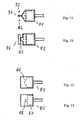
- FIG. 3 schematically shows a non-inventive pulsator 1 for a milking device for milking an animal, in particular a cow, with a device by means of which at least the time course of the evacuation phase and / or the ventilation phase is adjustable.
- the device has a valve 9.
- the valve comprises a chamber 10 in which a valve body 11 is movably arranged.
- the valve body 11 can be attached to a first valve seat 12 or to a second valve seat 13.
- valve body 11 rests on the first valve seat 12, so that a connection of a channel 14 with the chamber 10 is interrupted.
- the channel 14 is connected via a line, not shown, with a vacuum source (vacuum source).
- vacuum source vacuum source
- the second valve seat 13 opens a channel 15 which communicates with the ambient atmosphere.
- the chamber 10 communicates via a channel 16 with the milking machine.
- valve body has reached an end position in which a connection of a milking cup or the milking unit via the channel 16, the chamber 10 and the channel 15 is present with the ambient atmosphere, so that a ventilation of the pulse space of the milking cup takes place.
- the valve body 11 is preferably placed in a specific floating position, ie in a position between its end positions, as shown in the FIG. 3 is shown.
- the valve body passes out of the floating position, the area between the end positions.
- the position of the valve body 11 or the valve cross-section results from the driving forces and moments and the opposing forces acting in the valve due to friction, weight, spring forces or other restoring forces or the like, and in particular the pressure in the valve. Therefore, there is a continuous relationship between control force / torque and valve cross-section. This is reflected in a valve characteristic.
- the control of the valve 9 takes place in dependence on a valve characteristic, whereby the course of the evacuation phase and / or the ventilation phase can be adjusted accordingly.
- the valve 9 is preferably an electromagnetic valve.
- the valve body can have permanent magnetic properties.
- the applied for the displacement of the valve body forces come from preferably two substantially axially behind one another arranged coils with opposite winding sense, which form electromagnets with opposite poles in current flow.
- the valve body can move axially along the coil axes, up to the first and the second valve seat.
- FIG. 5 shows a non-inventive pulsator 20 for a milking device for milking an animal, in particular a cow, wherein the pulsator comprises means by which at least the time course of the evacuation phase and / or the ventilation phase is adjustable.
- the device comprises a pilot valve 21 and a main valve 20.
- the pilot valve 21 has a chamber 23 in which a valve body 24 is movable back and forth between two end positions.
- the channel 25 is connected via a non-illustrated connection of the pulsator with a vacuum source.
- the mouth of the channel 25 is closed by the valve body 24.
- the mouth of the channel 27 is closed in another position of the valve body 24.
- the channel 27 connects the chamber 23 with the ambient atmosphere.
- the chamber 23 is connected to an upper space 31.
- the upper space 31 is formed in a housing 28. This is limited by the housing and by a diaphragm 29 which is elastic. With the membrane 29, a valve body 30 of the main valve 22 is connected.
- the valve body has sealing surfaces 32, 33. The valve surface 32 is for abutment against the valve seat 34 while the sealing surface 33 is attachable to the valve seat 35.
- the valve body 30 is arranged in a chamber 36.
- the chamber 36 communicates via a passage 37 in communication with a lower space 38 bounded by the housing 28 and the diaphragm 29.
- the chamber 36 opens a channel 39 which is connectable to the pulse space of a milking cup.
- the chamber 36 of the main valve 22 is also connectable to a vacuum source via the channel 40.
- an opening 41 is provided, so that the lower space 38 is in communication with the ambient atmosphere.
- the pilot valve 21 is preferably a valve which is operated largely binary. If the valve body 24 of the pilot valve 21 is moved upward, it closes the mouth of the channel 27, so that the connection of the chamber 23 is interrupted with the ambient atmosphere. At the same time the mouth of the channel 25 is released. About the channel 25 and the channel 40 is formed within the chamber 23, a negative pressure, since the chamber 23 is now connected via the channel 25 and the channel 40 with a vacuum source. Due to the channel 26, which connects the chamber 23 with the upper space 31, created at the diaphragm 29, a pressure difference, since in the upper space 31, there is a lower pressure than in the lower chamber 38.
- the forces acting through the pressure difference on the Membranes 29 cause the diaphragm 29 to move upwards, ie in the direction of the upper space 31. Due to the rigid connection of the valve body 30 of the main valve 22 with the diaphragm, the valve body 30 is moved as far in the direction of the valve seat 35 until the valve face 33 rests on the valve seat 35. The speed at which the valve body 30 moves in the direction of the valve seat 35 is also dependent on the volume of the upper space 31.
- valve body 30 During the movement of the valve body 30, the free flow cross-section for the connection of the channels 39 and 40 will increase, while the connecting cross-section between the lower space 38 and the channel 39 decreases. In its end position, the valve face 33 of the valve body 30 bears against the valve seat 35.
- the pilot valve 21 is activated.
- the valve body 24 of the pilot valve 21 is moved such that the valve body closes the mouth of the channel 25 in the space 23 of the pilot valve 21.
- the mouth of the channel 27 is opened, so that a connection between the atmosphere of the environment and the chamber 23 is established.
- the valve body moves away from the valve seat 35 in the direction of the valve seat 34, so that the milking over the channel 39, the chamber 36 of the main valve and the passage 37 comes into contact with the ambient atmosphere, whereby aeration of the pulse space of the Melkzeugs takes place.
- FIG. 6 shows a further non-inventive pulsator.
- the pulsator 50 differs from that in the FIG. 5 represented pulsator 20 characterized in that in the channel 26, an element 51 is provided which forms a flow resistance. The time course of the evacuation phase is dependent on the element 51.
- FIGS. 7 to 10 is another, non-inventive pulsator 70 is shown.
- the pulsator 70 is in Fig. 7 shown in section. He is in the ventilation phase. This is a slide valve. The slider 73 releases the opening 74 in this position. The tip 76 of the slider is triangular. At the Change from the in FIGS. 8 and 10 shown evacuation phase in the ventilation phase, the slider 73 in the illustration of the Fig. 7 to 10 pulled to the right against the biasing force of the spring 75. In this case, the triangular tip 76 of the slide 73 initially releases small areas of the opening 74 next to the foremost point 76 for ventilation and an initially small air flow can flow to the pulse space of the teat cup.
- the released portion of the opening With increasing travel towards the end stop, the released portion of the opening becomes larger and the rate of pressure increase increases compared to a conventional system in which the entire cross section is opened simultaneously or nearly simultaneously because of the time required for a conventional slide to open is in the range of a few milliseconds.
- the slider 73 is held by appropriate pulses in a floating position and releases the opening only slowly and controlled.
- a solenoid (not shown) can be provided, which can be kept in a floating position particularly simple by electrical impulses.
- the evacuation port 78 is also triangular and in FIGS. 8 and 10 dashed lines. If, starting from the d-phase, the pulse space is to be evacuated again, the a-phase, ie the evacuation phase, is initiated. For this purpose, the slider 73 from the in FIGS. 7 and 9 shown position moves to the left, so that the vacuum supply line 72 is connected via the slider 73 with the pulse chamber terminal 71 of the milking cup. In turn, the straight edge of the slider 73 cooperates with the tip of the triangular evacuation port 78. First, a small cross-section is now released. As the travel increases, the cross section becomes larger and the evacuation speed increases.
- the control can be done floating in all these cases. Or the slide is moved accordingly slow. This can be done, for example, by a suitable vacuum on the control vacuum line 77.
- FIG. 11 shows a pulsator according to the invention.
- FIGS. 12 to 14 Further Ausftihrungsbei admir of sliding pulsators 73 are shown.
- the slider 81 off Fig. 11 has a triangular tip, as the slider 73 from Fig. 7 , After the pulsator Fig. 11 but are three ventilation openings 91 and 92 provided in the slide plate.
- the two laterally arranged from the central axis of symmetry ventilation opening 92 are initially opened and a relatively small air flow can enter the channel 71. After further displacement, the opening 91 is released and the pressure change rate increases.
- the slider 82 after Fig. 12 has a rectangular projection at the front, so that when pulling back the lateral areas are released, before finally the whole - here as in Fig. 7 rectangular designed vent 93 - is released.
- slides 84 and 85 are provided for control of the evacuation phase.
- the cavity 86 is designed triangular in the direction of the pulse space line 71 to the teat cup and the slider 85 has in the front region of the cavity 87 has a narrow tail 88, which first comes into contact with the pulse space line 71.
- two and more different speeds of a pressure change phase can thus be set according to the invention.
Landscapes
- Life Sciences & Earth Sciences (AREA)
- Animal Husbandry (AREA)
- Environmental Sciences (AREA)
- External Artificial Organs (AREA)
- Housing For Livestock And Birds (AREA)
Claims (18)
- Procédé pour la traite mécanique d'un animal, par exemple d'une vache, par lequel est créée une dépression pulsatoire dans une chambre de pulsation d'un gobelet trayeur (3), la dépression dans la chambre de pulsation changeant pendant les phases de variation de pression, et par lequel l'évolution de la pression est contrôlée pendant au moins une phase de variation de pression (a, c) par le biais d'un ajustement d'un dispositif de commande à au moins deux vitesses,
caractérisé en ce
que l'évolution temporelle d'au moins une phase de variation de pression (a, c) est réglée en fonction d'une caractéristique d'une valve (9) à au moins deux ouvertures de valve (91, 92) du pulsateur (1, 20, 50, 70), la section de passage de la valve du pulsateur étant modifiée pour modifier la vitesse au cours de la phase de variation de pression. - Procédé selon la revendication 1, l'évolution de la pression étant contrôlée pendant la phase d'arrivée d'air (c) et/ou pendant la phase d'évacuation de l'air (a).
- Procédé selon l'une quelconque des revendications précédentes, la vitesse de la variation de pression étant sensiblement continue au cours d'un intervalle de temps.
- Procédé selon l'une quelconque des revendications précédentes, la phase d'évacuation de l'air (a) et/ou la phase d'arrivée d'air (c) étant sensiblement discontinues au moins au cours d'un intervalle de temps.
- Procédé selon l'une quelconque des revendications précédentes, l'évolution de la pression étant contrôlée sur un premier intervalle de temps et sur un intervalle suivant de la phase d'arrivée d'air (c) de telle sorte que la pression est plus basse au cours du premier intervalle de temps qu'au cours de l'intervalle suivant.
- Procédé selon l'une quelconque des revendications précédentes, l'évolution de la pression étant contrôlée sur un premier intervalle de temps et sur un intervalle suivant de la phase d'évacuation de l'air (a) de telle sorte que la pression est plus élevée au cours du premier intervalle qu'au cours de l'intervalle suivant.
- Procédé selon l'une quelconque des revendications précédentes, le passage entre le premier et le deuxième intervalle de temps étant commuté lorsque la pression dans la chambre de pulsation a atteint un niveau où le manchon trayeur est comprimé.
- Procédé selon l'une quelconque des revendications précédentes, la section de passage d'une valve (9, 21, 22) du pulsateur (1, 20, 50, 70) étant modifiée en plusieurs étapes.
- Procédé selon l'une quelconque des revendications précédentes, la section de passage d'une valve (9, 21, 22) du pulsateur (1, 20, 50, 70) étant modifiée en continu.
- Procédé selon l'une quelconque des revendications précédentes, la pression en chambre de pulsation étant mesurée, cette pression générant un signal d'entrée d'une unité physique, ladite unité physique livrant un signal de sortie mettant en marche le pulsateur et/ou arrêtant la résistance à l'écoulement.
- Pulsateur pour un dispositif de traite pour traire un animal, par exemple une vache, pour relier en alternance une source de dépression et de pression (5) à une chambre de pulsation d'au moins un gobelet trayeur (3), un dispositif étant prévu permettant de contrôler au moins l'évolution temporelle de la pression pendant au moins une phase de variation de pression (a, c) à au moins deux vitesses,
caractérisé en ce
que le pulsateur présente au moins une valve (9, 20, 21) et que l'évolution temporelle d'au moins une phase de variation de la pression (a, c) est ajustable en fonction d'une caractéristique de la valve (9, 21, 22), la section de passage de valve de la valve du pulsateur étant modifiable pour modifier la vitesse au cours de la phase de variation de pression, et la valve présentant au moins deux ouvertures de valves (91, 92). - Pulsateur selon la revendication 11, caractérisé en ce que le dispositif présente au moins un relais de temporisation qui permet d'ajuster la durée d'un intervalle d'une phase de variation de pression (a, c).
- Pulsateur selon la revendication 11 ou 12, la pression étant réglable au moins pendant la phase d'arrivée d'air (c) et/ou pendant la phase d'évacuation de l'air (a).
- Pulsateur selon l'une quelconque des revendications 11 à 13, caractérisé en ce qu'une valve de pulsation est prévue, dont la section d'ouverture (73, 74) est modifiable.
- Pulsateur selon l'une quelconque des revendications 11 à 14, caractérisé en ce que le dispositif présente une valve pilote (21) et une valve principale (22).
- Pulsateur selon l'une quelconque des revendications 11 à 15, caractérisé en ce que le dispositif présente au moins une valve directe.
- Pulsateur selon l'une quelconque des revendications 11 à 16, caractérisé en ce que les deux ouvertures de valve (91, 92) présentent des sections différentes.
- Dispositif de traite comportant au moins un gobelet trayeur et un pulsateur correspondant, selon l'une quelconque des revendications 11 à 17, ainsi qu'une unité de mesure de la pression pour déterminer une pression dans la chambre de pulsation du gobelet trayeur, ladite unité générant un signal d'entrée pour ledit dispositif, lequel actionne le pulsateur et/ou l'élément.
Applications Claiming Priority (2)
| Application Number | Priority Date | Filing Date | Title |
|---|---|---|---|
| DE10326108A DE10326108A1 (de) | 2003-06-06 | 2003-06-06 | Verfahren zum Melken eines Tieres bei welchem ein Melkbecher mit einem Pulsator verbunden ist sowie eine Vorrichtung |
| PCT/EP2004/006128 WO2004107853A2 (fr) | 2003-06-06 | 2004-06-07 | Procede et dispositif pour traire un animal |
Publications (3)
| Publication Number | Publication Date |
|---|---|
| EP1631142A2 EP1631142A2 (fr) | 2006-03-08 |
| EP1631142B1 EP1631142B1 (fr) | 2011-08-10 |
| EP1631142B2 true EP1631142B2 (fr) | 2016-04-13 |
Family
ID=33482747
Family Applications (1)
| Application Number | Title | Priority Date | Filing Date |
|---|---|---|---|
| EP04739661.9A Not-in-force EP1631142B2 (fr) | 2003-06-06 | 2004-06-07 | Procédé et dispositif pour traire un animal |
Country Status (5)
| Country | Link |
|---|---|
| US (1) | US8567345B2 (fr) |
| EP (1) | EP1631142B2 (fr) |
| AT (1) | ATE519363T1 (fr) |
| DE (1) | DE10326108A1 (fr) |
| WO (1) | WO2004107853A2 (fr) |
Families Citing this family (6)
| Publication number | Priority date | Publication date | Assignee | Title |
|---|---|---|---|---|
| DE102004059572A1 (de) * | 2004-12-09 | 2006-06-22 | Westfaliasurge Gmbh | Verfahren zum Melken eines Tieres |
| EP2252142B1 (fr) * | 2008-01-24 | 2016-10-26 | DeLaval Holding AB | Procédé pour le contrôle de traite par une machine à traire |
| KR101190058B1 (ko) * | 2012-01-19 | 2012-10-12 | 조용석 | 착유기 자동 점검 장치 및 방법 |
| DE102012005649A1 (de) | 2012-03-22 | 2013-09-26 | Gea Farm Technologies Gmbh | Verfahren zum Betreiben einer Melkanlage |
| WO2015084900A1 (fr) * | 2013-12-02 | 2015-06-11 | Guardian Research Technologies, LLC | Système de gestion de données et son procédé d'utilisation |
| NL2015944B1 (nl) * | 2015-12-11 | 2017-07-05 | Lely Patent Nv | Melkinrichting. |
Citations (1)
| Publication number | Priority date | Publication date | Assignee | Title |
|---|---|---|---|---|
| WO2005007766A1 (fr) † | 2003-07-07 | 2005-01-27 | Dow Global Technologies Inc. | Composition de colle epoxyde et son procede d'application |
Family Cites Families (15)
| Publication number | Priority date | Publication date | Assignee | Title |
|---|---|---|---|---|
| US3125066A (en) * | 1964-03-17 | Milking machine analyzer | ||
| US2039421A (en) * | 1932-11-26 | 1936-05-05 | Laval Separator Co De | Process and apparatus for milking |
| SE460634B (sv) * | 1988-03-11 | 1989-11-06 | Alfa Laval Agri Int | Mjoelkningsmaskin och saett att mjoelka medelst densamma |
| SE9100242D0 (sv) * | 1991-01-25 | 1991-01-25 | Alfa Laval Agri Int | Saett att mjoelka |
| DE4312276C2 (de) * | 1993-04-15 | 1995-09-07 | Westfalia Separator Ag | Vorsteuerventil |
| IT1270881B (it) * | 1993-10-01 | 1997-05-13 | S El Pro Di Visigalli Ercolino | Mungitrice automatica |
| DE4335699C1 (de) * | 1993-10-20 | 1994-11-17 | Westfalia Separator Ag | Melkanlage |
| SE504429C2 (sv) * | 1995-05-17 | 1997-02-10 | Tetra Laval Holdings & Finance | Sätt att styra mjölkning med hjälp av spengummits abrupta rörelse jämte mjölkningsmaskin med avkännare härför |
| SE511014C2 (sv) * | 1995-12-22 | 1999-07-19 | Alfa Laval Agri Ab | Sätt att mjölka ett djur med hjälp av två olika tryck och mjölkningsmaskin med två tryckkällor |
| US5809931A (en) * | 1996-02-20 | 1998-09-22 | Alfa Laval Agri Ab | Method and apparatus for positioning milking cluster |
| US5897304A (en) * | 1996-12-16 | 1999-04-27 | Tetra Laval Holdings & Finance, Sa | Flow-through vertical filling pump with a plurality of diaphragms |
| DE10034892C2 (de) * | 2000-07-18 | 2002-06-20 | Westfalia Landtechnik Gmbh | Verfahren und Vorrichtung zur Steuerung und Überwachung einer Saugmelkanlage |
| DE10046276A1 (de) | 2000-09-19 | 2002-04-18 | Westfalia Landtechnik Gmbh | Verfahren und Vorrichtung zum verbesserten Ausmelken eines Tieres, insbesondere einer Kuh |
| US6553934B2 (en) * | 2001-01-03 | 2003-04-29 | Senseability, Inc. | Method and apparatus for monitoring milking facility pulsation |
| US6990924B2 (en) * | 2003-02-07 | 2006-01-31 | Global Tech Systems Inc | Controller for monitoring and controlling pulsators in a milking system |
-
2003
- 2003-06-06 DE DE10326108A patent/DE10326108A1/de not_active Withdrawn
-
2004
- 2004-06-07 WO PCT/EP2004/006128 patent/WO2004107853A2/fr active Application Filing
- 2004-06-07 AT AT04739661T patent/ATE519363T1/de active
- 2004-06-07 US US10/559,159 patent/US8567345B2/en not_active Expired - Fee Related
- 2004-06-07 EP EP04739661.9A patent/EP1631142B2/fr not_active Not-in-force
Patent Citations (1)
| Publication number | Priority date | Publication date | Assignee | Title |
|---|---|---|---|---|
| WO2005007766A1 (fr) † | 2003-07-07 | 2005-01-27 | Dow Global Technologies Inc. | Composition de colle epoxyde et son procede d'application |
Also Published As
| Publication number | Publication date |
|---|---|
| US8567345B2 (en) | 2013-10-29 |
| EP1631142A2 (fr) | 2006-03-08 |
| EP1631142B1 (fr) | 2011-08-10 |
| DE10326108A1 (de) | 2004-12-23 |
| US20060243210A1 (en) | 2006-11-02 |
| WO2004107853A2 (fr) | 2004-12-16 |
| ATE519363T1 (de) | 2011-08-15 |
| WO2004107853A3 (fr) | 2007-04-26 |
Similar Documents
| Publication | Publication Date | Title |
|---|---|---|
| DE69230765T3 (de) | Melkmaschine mit veränderlicher druckquelle | |
| EP0032752B1 (fr) | Procédé et dispositif de traite mécanique | |
| EP0643292B1 (fr) | Méthode et dispositif de prise d'un échantillon représentatif de la production de lait d'une vache | |
| DE202008004031U1 (de) | Vorrichtung zum Melken von Tieren | |
| DE1956196C3 (de) | Melkmaschine | |
| EP1631142B2 (fr) | Procédé et dispositif pour traire un animal | |
| WO2007060003A1 (fr) | Procede et dispositif de traite d'animaux | |
| EP1814380A1 (fr) | Dispositif pour stimuler un pis lors d'un processus de traite | |
| DE2423554A1 (de) | Melkmaschine | |
| EP1276368B1 (fr) | Gobelets trayeurs pour machines a traire | |
| DE3323676C2 (fr) | ||
| DE2046276C3 (de) | Melkbecher für Melkmaschinen | |
| EP1679955B1 (fr) | Dispositif et procédé pour le démarrage automatique d'un processus de traite | |
| EP1827084A1 (fr) | Procede de traite d'un animal | |
| AT393746B (de) | Verfahren und vorrichtung zur regelung des fuellstandes eines luftabscheiders | |
| DE3047579A1 (de) | Verfahren und vorrichtung zum maschinellen milchentzug | |
| EP2217056B1 (fr) | Dispositif pulsant | |
| DE2726020A1 (de) | Steuervorrichtung zur automatischen abnahme von melkorganen | |
| EP1318715B1 (fr) | Procede et dispositif pour ameliorer la traite d'un animal, en particulier d'une vache | |
| DD140190A5 (de) | Druckluft-zeitverzoegerungseinrichtung | |
| DE2241233C3 (de) | Pulsator für Melkmaschinen | |
| DE2746310A1 (de) | Verfahren und vorrichtung zum melken von tieren, insbesondere von kuehen | |
| DE2052232C3 (de) | Blockiergeschützte hydraulische Kraftfahrzeugbremsanlage | |
| DE156286C (fr) | ||
| DE1561999C (de) | Verfahren und Vorrichtung zum Füllen von Behältern mit feinzerteiltem pulverförmigen Gut |
Legal Events
| Date | Code | Title | Description |
|---|---|---|---|
| PUAI | Public reference made under article 153(3) epc to a published international application that has entered the european phase |
Free format text: ORIGINAL CODE: 0009012 |
|
| 17P | Request for examination filed |
Effective date: 20051228 |
|
| AK | Designated contracting states |
Kind code of ref document: A2 Designated state(s): AT BE BG CH CY CZ DE DK EE ES FI FR GB GR HU IE IT LI LU MC NL PL PT RO SE SI SK TR |
|
| AX | Request for extension of the european patent |
Extension state: AL HR LT LV MK |
|
| DAX | Request for extension of the european patent (deleted) | ||
| PUAK | Availability of information related to the publication of the international search report |
Free format text: ORIGINAL CODE: 0009015 |
|
| RAP1 | Party data changed (applicant data changed or rights of an application transferred) |
Owner name: GEA WESTFALIASURGE GMBH |
|
| GRAP | Despatch of communication of intention to grant a patent |
Free format text: ORIGINAL CODE: EPIDOSNIGR1 |
|
| GRAS | Grant fee paid |
Free format text: ORIGINAL CODE: EPIDOSNIGR3 |
|
| GRAA | (expected) grant |
Free format text: ORIGINAL CODE: 0009210 |
|
| RAP1 | Party data changed (applicant data changed or rights of an application transferred) |
Owner name: GEA FARM TECHNOLOGIES GMBH |
|
| AK | Designated contracting states |
Kind code of ref document: B1 Designated state(s): AT BE BG CH CY CZ DE DK EE ES FI FR GB GR HU IE IT LI LU MC NL PL PT RO SE SI SK TR |
|
| REG | Reference to a national code |
Ref country code: GB Ref legal event code: FG4D Free format text: NOT ENGLISH |
|
| REG | Reference to a national code |
Ref country code: CH Ref legal event code: EP |
|
| REG | Reference to a national code |
Ref country code: IE Ref legal event code: FG4D Free format text: LANGUAGE OF EP DOCUMENT: GERMAN |
|
| REG | Reference to a national code |
Ref country code: DE Ref legal event code: R096 Ref document number: 502004012782 Country of ref document: DE Effective date: 20111020 |
|
| REG | Reference to a national code |
Ref country code: NL Ref legal event code: T3 |
|
| REG | Reference to a national code |
Ref country code: SE Ref legal event code: TRGR |
|
| PG25 | Lapsed in a contracting state [announced via postgrant information from national office to epo] |
Ref country code: PT Free format text: LAPSE BECAUSE OF FAILURE TO SUBMIT A TRANSLATION OF THE DESCRIPTION OR TO PAY THE FEE WITHIN THE PRESCRIBED TIME-LIMIT Effective date: 20111212 Ref country code: FI Free format text: LAPSE BECAUSE OF FAILURE TO SUBMIT A TRANSLATION OF THE DESCRIPTION OR TO PAY THE FEE WITHIN THE PRESCRIBED TIME-LIMIT Effective date: 20110810 |
|
| PG25 | Lapsed in a contracting state [announced via postgrant information from national office to epo] |
Ref country code: GR Free format text: LAPSE BECAUSE OF FAILURE TO SUBMIT A TRANSLATION OF THE DESCRIPTION OR TO PAY THE FEE WITHIN THE PRESCRIBED TIME-LIMIT Effective date: 20111111 Ref country code: CY Free format text: LAPSE BECAUSE OF FAILURE TO SUBMIT A TRANSLATION OF THE DESCRIPTION OR TO PAY THE FEE WITHIN THE PRESCRIBED TIME-LIMIT Effective date: 20110810 Ref country code: SI Free format text: LAPSE BECAUSE OF FAILURE TO SUBMIT A TRANSLATION OF THE DESCRIPTION OR TO PAY THE FEE WITHIN THE PRESCRIBED TIME-LIMIT Effective date: 20110810 Ref country code: PL Free format text: LAPSE BECAUSE OF FAILURE TO SUBMIT A TRANSLATION OF THE DESCRIPTION OR TO PAY THE FEE WITHIN THE PRESCRIBED TIME-LIMIT Effective date: 20110810 |
|
| REG | Reference to a national code |
Ref country code: IE Ref legal event code: FD4D |
|
| PG25 | Lapsed in a contracting state [announced via postgrant information from national office to epo] |
Ref country code: SK Free format text: LAPSE BECAUSE OF FAILURE TO SUBMIT A TRANSLATION OF THE DESCRIPTION OR TO PAY THE FEE WITHIN THE PRESCRIBED TIME-LIMIT Effective date: 20110810 Ref country code: IE Free format text: LAPSE BECAUSE OF FAILURE TO SUBMIT A TRANSLATION OF THE DESCRIPTION OR TO PAY THE FEE WITHIN THE PRESCRIBED TIME-LIMIT Effective date: 20110810 Ref country code: CZ Free format text: LAPSE BECAUSE OF FAILURE TO SUBMIT A TRANSLATION OF THE DESCRIPTION OR TO PAY THE FEE WITHIN THE PRESCRIBED TIME-LIMIT Effective date: 20110810 |
|
| PLBI | Opposition filed |
Free format text: ORIGINAL CODE: 0009260 |
|
| PG25 | Lapsed in a contracting state [announced via postgrant information from national office to epo] |
Ref country code: EE Free format text: LAPSE BECAUSE OF FAILURE TO SUBMIT A TRANSLATION OF THE DESCRIPTION OR TO PAY THE FEE WITHIN THE PRESCRIBED TIME-LIMIT Effective date: 20110810 Ref country code: IT Free format text: LAPSE BECAUSE OF FAILURE TO SUBMIT A TRANSLATION OF THE DESCRIPTION OR TO PAY THE FEE WITHIN THE PRESCRIBED TIME-LIMIT Effective date: 20110810 Ref country code: RO Free format text: LAPSE BECAUSE OF FAILURE TO SUBMIT A TRANSLATION OF THE DESCRIPTION OR TO PAY THE FEE WITHIN THE PRESCRIBED TIME-LIMIT Effective date: 20110810 |
|
| PLAX | Notice of opposition and request to file observation + time limit sent |
Free format text: ORIGINAL CODE: EPIDOSNOBS2 |
|
| 26 | Opposition filed |
Opponent name: OCTROOIBUREAU VAN DER LELY N.V. Effective date: 20120510 |
|
| PG25 | Lapsed in a contracting state [announced via postgrant information from national office to epo] |
Ref country code: DK Free format text: LAPSE BECAUSE OF FAILURE TO SUBMIT A TRANSLATION OF THE DESCRIPTION OR TO PAY THE FEE WITHIN THE PRESCRIBED TIME-LIMIT Effective date: 20110810 |
|
| REG | Reference to a national code |
Ref country code: DE Ref legal event code: R026 Ref document number: 502004012782 Country of ref document: DE Effective date: 20120510 |
|
| PLAF | Information modified related to communication of a notice of opposition and request to file observations + time limit |
Free format text: ORIGINAL CODE: EPIDOSCOBS2 |
|
| PLBB | Reply of patent proprietor to notice(s) of opposition received |
Free format text: ORIGINAL CODE: EPIDOSNOBS3 |
|
| BERE | Be: lapsed |
Owner name: GEA FARM TECHNOLOGIES G.M.B.H. Effective date: 20120630 |
|
| PG25 | Lapsed in a contracting state [announced via postgrant information from national office to epo] |
Ref country code: MC Free format text: LAPSE BECAUSE OF NON-PAYMENT OF DUE FEES Effective date: 20120630 |
|
| REG | Reference to a national code |
Ref country code: CH Ref legal event code: PL |
|
| REG | Reference to a national code |
Ref country code: CH Ref legal event code: PL |
|
| GBPC | Gb: european patent ceased through non-payment of renewal fee |
Effective date: 20120607 |
|
| REG | Reference to a national code |
Ref country code: FR Ref legal event code: ST Effective date: 20130228 |
|
| PG25 | Lapsed in a contracting state [announced via postgrant information from national office to epo] |
Ref country code: BE Free format text: LAPSE BECAUSE OF NON-PAYMENT OF DUE FEES Effective date: 20120630 Ref country code: CH Free format text: LAPSE BECAUSE OF NON-PAYMENT OF DUE FEES Effective date: 20120630 Ref country code: LI Free format text: LAPSE BECAUSE OF NON-PAYMENT OF DUE FEES Effective date: 20120630 Ref country code: ES Free format text: LAPSE BECAUSE OF FAILURE TO SUBMIT A TRANSLATION OF THE DESCRIPTION OR TO PAY THE FEE WITHIN THE PRESCRIBED TIME-LIMIT Effective date: 20111121 Ref country code: GB Free format text: LAPSE BECAUSE OF NON-PAYMENT OF DUE FEES Effective date: 20120607 Ref country code: FR Free format text: LAPSE BECAUSE OF NON-PAYMENT OF DUE FEES Effective date: 20120702 |
|
| PG25 | Lapsed in a contracting state [announced via postgrant information from national office to epo] |
Ref country code: BG Free format text: LAPSE BECAUSE OF FAILURE TO SUBMIT A TRANSLATION OF THE DESCRIPTION OR TO PAY THE FEE WITHIN THE PRESCRIBED TIME-LIMIT Effective date: 20111110 |
|
| REG | Reference to a national code |
Ref country code: AT Ref legal event code: MM01 Ref document number: 519363 Country of ref document: AT Kind code of ref document: T Effective date: 20120607 |
|
| PG25 | Lapsed in a contracting state [announced via postgrant information from national office to epo] |
Ref country code: AT Free format text: LAPSE BECAUSE OF NON-PAYMENT OF DUE FEES Effective date: 20120607 |
|
| PG25 | Lapsed in a contracting state [announced via postgrant information from national office to epo] |
Ref country code: TR Free format text: LAPSE BECAUSE OF FAILURE TO SUBMIT A TRANSLATION OF THE DESCRIPTION OR TO PAY THE FEE WITHIN THE PRESCRIBED TIME-LIMIT Effective date: 20110810 |
|
| PG25 | Lapsed in a contracting state [announced via postgrant information from national office to epo] |
Ref country code: LU Free format text: LAPSE BECAUSE OF NON-PAYMENT OF DUE FEES Effective date: 20120607 |
|
| PG25 | Lapsed in a contracting state [announced via postgrant information from national office to epo] |
Ref country code: HU Free format text: LAPSE BECAUSE OF FAILURE TO SUBMIT A TRANSLATION OF THE DESCRIPTION OR TO PAY THE FEE WITHIN THE PRESCRIBED TIME-LIMIT Effective date: 20040607 |
|
| PLAY | Examination report in opposition despatched + time limit |
Free format text: ORIGINAL CODE: EPIDOSNORE2 |
|
| PLBC | Reply to examination report in opposition received |
Free format text: ORIGINAL CODE: EPIDOSNORE3 |
|
| PLAP | Information related to despatch of examination report in opposition + time limit deleted |
Free format text: ORIGINAL CODE: EPIDOSDORE2 |
|
| PLAT | Information related to reply to examination report in opposition deleted |
Free format text: ORIGINAL CODE: EPIDOSDORE3 |
|
| PLAY | Examination report in opposition despatched + time limit |
Free format text: ORIGINAL CODE: EPIDOSNORE2 |
|
| PLBC | Reply to examination report in opposition received |
Free format text: ORIGINAL CODE: EPIDOSNORE3 |
|
| PLAL | Information related to reply to examination report in opposition modified |
Free format text: ORIGINAL CODE: EPIDOSCORE3 |
|
| PLAB | Opposition data, opponent's data or that of the opponent's representative modified |
Free format text: ORIGINAL CODE: 0009299OPPO |
|
| PUAH | Patent maintained in amended form |
Free format text: ORIGINAL CODE: 0009272 |
|
| STAA | Information on the status of an ep patent application or granted ep patent |
Free format text: STATUS: PATENT MAINTAINED AS AMENDED |
|
| R26 | Opposition filed (corrected) |
Opponent name: OCTROOIBUREAU VAN DER LELY N.V. Effective date: 20120510 |
|
| 27A | Patent maintained in amended form |
Effective date: 20160413 |
|
| AK | Designated contracting states |
Kind code of ref document: B2 Designated state(s): AT BE BG CH CY CZ DE DK EE ES FI FR GB GR HU IE IT LI LU MC NL PL PT RO SE SI SK TR |
|
| REG | Reference to a national code |
Ref country code: DE Ref legal event code: R102 Ref document number: 502004012782 Country of ref document: DE |
|
| REG | Reference to a national code |
Ref country code: SE Ref legal event code: RPEO |
|
| REG | Reference to a national code |
Ref country code: NL Ref legal event code: FP |
|
| PGFP | Annual fee paid to national office [announced via postgrant information from national office to epo] |
Ref country code: NL Payment date: 20180622 Year of fee payment: 15 |
|
| PGFP | Annual fee paid to national office [announced via postgrant information from national office to epo] |
Ref country code: SE Payment date: 20180622 Year of fee payment: 15 |
|
| PGFP | Annual fee paid to national office [announced via postgrant information from national office to epo] |
Ref country code: DE Payment date: 20190702 Year of fee payment: 16 |
|
| REG | Reference to a national code |
Ref country code: SE Ref legal event code: EUG |
|
| PG25 | Lapsed in a contracting state [announced via postgrant information from national office to epo] |
Ref country code: SE Free format text: LAPSE BECAUSE OF NON-PAYMENT OF DUE FEES Effective date: 20190608 |
|
| REG | Reference to a national code |
Ref country code: NL Ref legal event code: MM Effective date: 20190701 |
|
| PG25 | Lapsed in a contracting state [announced via postgrant information from national office to epo] |
Ref country code: NL Free format text: LAPSE BECAUSE OF NON-PAYMENT OF DUE FEES Effective date: 20190701 |
|
| REG | Reference to a national code |
Ref country code: DE Ref legal event code: R119 Ref document number: 502004012782 Country of ref document: DE |
|
| PG25 | Lapsed in a contracting state [announced via postgrant information from national office to epo] |
Ref country code: DE Free format text: LAPSE BECAUSE OF NON-PAYMENT OF DUE FEES Effective date: 20210101 |