EP1631142B2 - Method and device for milking an animal - Google Patents
Method and device for milking an animal Download PDFInfo
- Publication number
- EP1631142B2 EP1631142B2 EP04739661.9A EP04739661A EP1631142B2 EP 1631142 B2 EP1631142 B2 EP 1631142B2 EP 04739661 A EP04739661 A EP 04739661A EP 1631142 B2 EP1631142 B2 EP 1631142B2
- Authority
- EP
- European Patent Office
- Prior art keywords
- pressure
- valve
- pulsator
- phase
- milking
- Prior art date
- Legal status (The legal status is an assumption and is not a legal conclusion. Google has not performed a legal analysis and makes no representation as to the accuracy of the status listed.)
- Expired - Lifetime
Links
- 238000000034 method Methods 0.000 title claims abstract description 42
- 241001465754 Metazoa Species 0.000 title claims abstract description 28
- 230000008859 change Effects 0.000 claims abstract description 51
- 238000009423 ventilation Methods 0.000 claims abstract description 51
- 210000002445 nipple Anatomy 0.000 description 45
- 230000033001 locomotion Effects 0.000 description 21
- 238000005273 aeration Methods 0.000 description 15
- 230000008569 process Effects 0.000 description 12
- 238000007667 floating Methods 0.000 description 10
- 230000010349 pulsation Effects 0.000 description 10
- 239000008267 milk Substances 0.000 description 8
- 210000004080 milk Anatomy 0.000 description 8
- 235000013336 milk Nutrition 0.000 description 8
- 230000002829 reductive effect Effects 0.000 description 7
- 241000283690 Bos taurus Species 0.000 description 6
- 230000000694 effects Effects 0.000 description 4
- 230000003247 decreasing effect Effects 0.000 description 3
- 238000001514 detection method Methods 0.000 description 3
- 238000007726 management method Methods 0.000 description 3
- 239000012528 membrane Substances 0.000 description 3
- 230000004044 response Effects 0.000 description 3
- 230000000638 stimulation Effects 0.000 description 3
- 230000007704 transition Effects 0.000 description 3
- 230000008901 benefit Effects 0.000 description 2
- 238000004891 communication Methods 0.000 description 2
- 230000007423 decrease Effects 0.000 description 2
- 230000001419 dependent effect Effects 0.000 description 2
- 238000006073 displacement reaction Methods 0.000 description 2
- 230000006870 function Effects 0.000 description 2
- 244000144980 herd Species 0.000 description 2
- 230000002028 premature Effects 0.000 description 2
- 238000004886 process control Methods 0.000 description 2
- 230000009467 reduction Effects 0.000 description 2
- 238000007789 sealing Methods 0.000 description 2
- 230000035807 sensation Effects 0.000 description 2
- 238000013022 venting Methods 0.000 description 2
- 235000002198 Annona diversifolia Nutrition 0.000 description 1
- 241000282832 Camelidae Species 0.000 description 1
- 241000282836 Camelus dromedarius Species 0.000 description 1
- 241000283707 Capra Species 0.000 description 1
- 241000282838 Lama Species 0.000 description 1
- 241001494479 Pecora Species 0.000 description 1
- 230000006978 adaptation Effects 0.000 description 1
- 230000002411 adverse Effects 0.000 description 1
- 230000032683 aging Effects 0.000 description 1
- 238000010009 beating Methods 0.000 description 1
- 230000015572 biosynthetic process Effects 0.000 description 1
- 210000000481 breast Anatomy 0.000 description 1
- 210000000078 claw Anatomy 0.000 description 1
- 238000013461 design Methods 0.000 description 1
- 238000011161 development Methods 0.000 description 1
- 230000018109 developmental process Effects 0.000 description 1
- 239000013013 elastic material Substances 0.000 description 1
- 210000003746 feather Anatomy 0.000 description 1
- 244000144993 groups of animals Species 0.000 description 1
- 230000003993 interaction Effects 0.000 description 1
- 239000000463 material Substances 0.000 description 1
- 238000012544 monitoring process Methods 0.000 description 1
- 230000036961 partial effect Effects 0.000 description 1
- 230000004962 physiological condition Effects 0.000 description 1
- 230000036316 preload Effects 0.000 description 1
- 238000004321 preservation Methods 0.000 description 1
- 230000000284 resting effect Effects 0.000 description 1
- 238000004904 shortening Methods 0.000 description 1
- 238000005507 spraying Methods 0.000 description 1
- 230000002123 temporal effect Effects 0.000 description 1
- 238000004804 winding Methods 0.000 description 1
Images


Classifications
-
- A—HUMAN NECESSITIES
- A01—AGRICULTURE; FORESTRY; ANIMAL HUSBANDRY; HUNTING; TRAPPING; FISHING
- A01J—MANUFACTURE OF DAIRY PRODUCTS
- A01J5/00—Milking machines or devices
- A01J5/007—Monitoring milking processes; Control or regulation of milking machines
Definitions
- the object of the invention relates to a method for the automatic milking of an animal, for example a cow, in which a pulsating negative pressure with successive evacuation phases and ventilation phases is generated in a teat cup via an associated pulsator, as well as on a pulsator.
- a pulsating negative pressure with successive evacuation phases and ventilation phases is generated in a teat cup via an associated pulsator, as well as on a pulsator.
- a substantially uniformly pulsating negative pressure is generated in the pulse space of a milking cup in order to set a teat cup provided in the teat space in the interior of the milking cup into a pulsating milking movement.
- the vacuum device of a Saugmelkstrom comprises a vacuum pump, a vacuum valve, pressure connection lines to the teat cups and a control device for generating valve control pulses.
- a valve opening pulse and valve closing pulse is generated.
- the vacuum pump of the system generates a substantially constant negative pressure, which corresponds approximately to the pulsation pressure.
- control device At fixed predetermined time intervals, the control device generates control signals for opening the valve of the vacuum device, so that a negative pressure is built up substantially abruptly in the teat cup space. This vacuum will maintained over a fixed period of time. As in the case of vacuum build-up, after receiving a further control pulse, the pressure in the milking-chamber gap is suddenly reduced by evacuating the pulse space again. Within a preset pulsation period, this process is repeated evenly.
- the pressure variation in the phase transitions is influenced in such a way that a slower pressure build-up or underpressure build-up is made possible and an improved compatibility achieved by making the phase transitions flatter.
- the problems arising due to sudden movements of the teatcup liner during vacuum or vacuum removal can thus be avoided.
- the existing pulsator valve is used by short-term driving with opening or closing pulses to flatten the pressure curve.
- a disadvantage of shallower pressure changes is the overall longer duration of a pulse cycle.
- Another disadvantage is the decreasing milking speed.
- a teatcup liner is set in motion in a teat cup by a suction vacuum via adjustable pulsation phases with alternating suction phases and relief phases and a pulsation intensity in order to achieve a milk flow.
- the milk volume flow is recorded continuously, whereby the teat rubber movement is selectively changed with a decreasing volume flow.
- the patent US 5,970,910 describes a milking method and associated MelkVorraum, in which for the preservation of the teats of an animal to be milked while reducing the residual milk quantity a ventilation operation for setting a normal pressure and / or an evacuation process for adjusting a negative pressure of a pulsation chamber in a teat cup is carried out in each case with different pressure gradients.
- the pressure gradient is changed when the instantaneous pressure reaches a predeterminable average pressure between the lowest pressure and the normal air pressure that can be generated by a pump in the device.
- the present invention is based on the object of specifying a method and a device by means of which a more gentle milking of an animal at an acceptable speed is made possible.
- a pulsating negative pressure is generated in a pulse space of a milking cup by changing the negative pressure in the pulse space in the pressure change phases.
- the pressure profile is controlled during at least one pressure change phase via an adjustment of an actuating unit in at least two speeds.
- the method is characterized in that the time course of the evacuation phase and / or the ventilation phase is adjusted in dependence on a valve characteristic of a valve having at least two valve openings of the pulsator, wherein the valve cross-section of the valve of the pulsator is changed to change the speed during the pressure change phase.
- a change in pressure phase can be understood to mean the evacuation phase and / or also the ventilation phase of a pulsator cycle.
- the pressure curve is the speed of a pressure change over time. Faster pressure changes produce steeper pressure gradients than slower pressure changes with flatter pressure gradients.
- the process control according to the invention has many advantages. Due to the two speeds, with which a pressure change can be effected, on the one hand a sufficiently fast milking can be achieved while, on the other hand, the teat is gently treated.
- the ventilation phase can be divided into two sections. In the first section, the pressure build-up can then take place at a lower speed than in the second section.
- the pulsating negative pressure is adjusted via a pulsator, wherein the pressure profile during the pressure change phase (s) is preferably controlled by means of an adjustment of an actuating device.
- the actuator may e.g. electrically or mechanically controlled and it can change a mechanical manipulated variable, such. a flow cross-section.
- the aeration phase is referred to as the period in which the vacuum level drops from the highest value in the pulse space to a predetermined lowest vacuum value.
- the invention is based on the basic idea that the time course of the evacuation phase and / or the aeration phase is set by means of two pressure change rates.
- the respective period required by a pressure change phase is only marginally longer than in the prior art. At a correspondingly greater ventilation speed after applying the teatcup liner to the teat, which is then harmless, the period can remain the same length.
- the course of the pressure drop or pressure increase has an effect on the speed of movement of the teatcup liner.
- a corresponding opening and / or closing speed of the teatcup liner is achieved.
- B a correlation produced, which is used in an advantageous manner for the milking process.
- the pressure profile is controlled at least during the venting phase in order to prevent the teatcup from hitting the teat.
- the pressure profile can also be controlled at least during the evacuation phase.
- the rate of pressure change within a period of time is substantially continuous. It can also be provided more than two time periods and / or more than two speeds of pressure change, for each three. Then, the pressure can be changed faster first, until about the folding pressure of the teatcup liner is reached, then slower until the teatcup liner has been gently closed or opened, then again close faster or open.
- the time profile of at least one pressure change phase namely the evacuation phase and / or the ventilation phase is discontinuous at least within a section.
- the pressure profile in a first section and in a following section of the aeration phase is controlled such that the pressure profile in the first section is flatter than in the following section, and particularly preferably considerably flatter.
- the pressure in the pulse space is then increased to about the folding-in pressure.
- the teatcup liner slowly settles and an unpleasant beating on the teat is significantly reduced or even prevented. Thereafter, the pressure build-up is faster and the pressure curve is steeper.
- the pressure profile in a first section and in a subsequent section of the evacuation phase is controlled such that the pressure profile in the first section is flatter than in the following section, and preferably considerably shallower.
- the pressure is reduced until the pressure difference between the pulse chamber and the teat chamber corresponds approximately to the folding-in pressure, and is preferably somewhat smaller, so that the teatcup liner has lifted off. Thereafter, the speed of the pressure change is increased and the pressure curve becomes steeper, to ensure a quicker progression after the slow lift off. This prevents the so-called and unwanted back-spraying of milk on the teat.
- three sections are possible, wherein in a first and third section, the speed is high and in the second section in a pressure range in the vicinity of the fold-in speed is reduced.
- the rate of pressure change is lower and then faster after the teatcup liner has been applied to the teat.
- the switchover pressure is preferably approximately the respective fold-in pressure of the teatcup liner, that is to say the pressure at which the pressure difference between the pulse and teat chambers corresponds approximately to the fold-in pressure of the teatcup liner.
- the predetermined one Switching pressure is preferably adjustable.
- aeration phase it is preferable that, at a pressure difference, slightly larger than a folding pressure is switched from the lower pressure changing speed to a high pressure changing speed to prevent high-speed folding of the teatcup liner.
- the evacuation phase it is preferable that, at a pressure difference, slightly larger than a folding pressure is switched from the low pressure changing speed to a high pressure changing speed to prevent opening of the teatcup liner at a high speed.
- the method according to the invention makes it possible to adapt pulsators to a milking cup, a milking machine or several connected milking devices, organic milking devices, different tube lengths and cross sections, as well as volumes in the milking cup and milking cluster.
- the quality of the pulsation can thus also be controlled by software.
- an electronically tracked control of pulsation quality it is thus also possible to control the dynamic progress of the evacuation phase or the aeration phase.
- the duration of the evacuation phase and / or the aeration phase is set.
- the course of the pressure change during the duration of the evacuation phase and / or the aeration phase can be different. It is also possible to adjust the course according to the technical and / or physiological conditions of the plant or the animal within the specified duration.
- the method according to the invention can also be carried out in conjunction with modern control devices or control systems in the form of, for example, a herd management system. If such a control system has animal-specific data and if it is known which animal is to undergo milking, the course of the evacuation phase can take place and / or the ventilation phase are also set animal-specific. In particular, the speeds may be predetermined or customized.
- the different speeds of the pressure curve can be selected depending on the fold-in pressure of the teatcup liner intended for milking.
- the area of the phase relevant to the opening of the teatcup liner should be designed such that the resulting increase in volume within the teat cup does not result in a backspray effect in the direction of the teat.
- the time period responsible for the opening can be designed specifically.
- a first part of the flow cross-section are opened in the pulsator and later another part. This results in a variable speed of movement.
- Pulsators are known which have a different system structure.
- the purpose of a pulsator is to direct air of higher or lower pressure to the milking cup (s) via the pulsation tubes, which is used in conjunction with the vacuum applied to the tip of the teat and the atmospheric outside air to produce movement of the teatcup liner.
- the pulsator has at least one valve.
- the flow resistance is changed to the milking cup.
- the free flow cross section, in particular in the pulse tube, is changed is preferred.
- valve cross-section of a valve of the pulsator is changed in order to influence the speed during a pressure change phase.
- the valve cross section or the free flow cross section of a valve can do this be changed in several stages.
- the valve cross section can also be changed continuously by sliding a slide or the like over the valve openings or increasing the free flow cross section during the movement.
- a change of the cross-section takes place monotonically and particularly preferably strictly monotonically in the mathematical sense.
- the change takes place over a large part of the duration of the pressure change phase.
- the valve cross section may e.g. be changed over 25% or 50% of the time span.
- the duration of the change is then e.g. 35, 50 or 70 or even more milliseconds.
- the ratio of the two stages is preferably in the range between 1: 4 and 4: 1, more preferably between 1: 2 and 2: 1.
- the length of a section at two speed levels is about half the duration of the respective pressure change phase.
- the pulsator valve is held in at least a portion of a pressure change phase in a floating position by appropriate control pulses are applied to the valve.
- the floating control is basically as known from the prior art.
- the pulsator valve is held in a variable float position in at least a portion of a pressure change phase.
- a variable-time floating position is also preferred in which the opening cross-section is increased or decreased with increasing time.
- the pressure in the pulse space is detected and preferably forms an input signal of a structural unit, which supplies an output signal, by which the pulsator and / or a flow resistance is actuated.
- the pressure change speed is changed only in the movement periods of the teatcup liner so that the speed of movement of the teatcup liner is reduced and after the teatcup liner has closed is controlled to a larger, preferably maximum, rate of pressure change so that the actual pressure change phases remain the same length, as in the prior art. A shortening of the pressure change phases is possible.
- the evacuation phase of the pulsation is preferably subdivided into at least two regions, wherein the pressure drop per unit of time is designed differently.
- the maximum pressure drop is thus selected as a function of the folding pressure of the milking teatcup liner.
- a pulsator for a milking device for milking an animal, for example a cow, for alternately connecting a vacuum source and a pressure source with at least one teat cup is proposed.
- a device is provided by means of which at least the temporal pressure variation during at least one pressure change phase can be controlled in at least two speeds.
- the pulsator according to the invention is characterized in that it has at least one valve with at least two valve openings and the time profile of the at least one pressure change phase in response to a valve characteristic of the valve is adjustable, wherein the valve cross-section of the valve of the pulsator is variable to the speed during to change the pressure change phase.
- the movement of a teatcup liner can be changed or varied in an advantageous manner.
- the mechanical conditions on the milking device such as, for example, can also be adjusted.
- the preload, material and geometry of the teatcup liner are taken into account.
- the vacuum level can also be found in the course of the evacuation phase and / or the ventilation phase.
- the teatcup liner is made of an elastic material.
- the movement of the teatcup liner and the aging process can lead to a change in the movement of the teatcup liner over time. If the behavior of the teatcup liner is known, for example, as a function of the number of movements performed, this behavior can be taken into consideration as an input when it comes to setting the course of the evacuation phase and / or the ventilation phase.
- the device has at least one timing element, by means of which at least the duration of the evacuation phase and / or the ventilation phase can be set. It is also possible to adapt the behavior of the pulsator to the animal to be milked, if it is known which animal is currently undergoing a milking process. In this case, animal-specific data from a herd management system can be used to specify the course of the evacuation phases and / or the ventilation phases. There is also the possibility that for each animal or groups of animals specific courses of Pulsations horres be deposited. These courses are then queried when the relevant animal or group of animals is or will undergo a milking process. The variation or adjustability of the evacuation phase and / or the aeration phase can take place not only during a milking process but also during a stimulation process. In this case, different courses for a stimulation process or for a milking process can be used.
- Pulsatorventil whose opening cross-section is variable. This can be variable continuously or discontinuously. It is also possible that the opening cross-section is variable in several stages.
- the pulsator or the pulsator valve may have a pilot valve and a main valve.
- a design as a direct valve is also preferred.
- the valve has at least two valve openings whose opening cross-section is variable.
- the openings can be designed as bores. Likewise, non-circular cross sections are possible.
- the valve openings may have different cross sections.
- the pulsator according to the invention may have two openings, one of which is larger and one smaller.
- a first opening for a high rate of pressure change then has e.g. 3 mm or 5 mm in diameter, while a smaller one has a diameter of only 1 mm for slower pressure changes.
- the diameter of the opening of the conventional pulsator is a compromise between speed and load of the teat.
- the means of the pulsator may comprise an element which is a nozzle or orifice.
- the opening diameters are variable by e.g. corresponding panels are replaced.
- the pulsator advantageously comprises a valve closing element, which cooperates with the valve openings.
- the adjustment of the free flow cross-section is effected by an interaction of valve openings and valve closing element in the form of, for example, a sliding element in a sliding seat valve.
- the valve of the device With the valve of the device, the time course of the evacuation phase and / or the aeration phase in dependence on a valve characteristic of the valve can be adjusted.
- the valve may be, for example, a directly actuated sliding seat valve or else a pilot valve of a pulsator, which is specifically guided on a valve characteristic.
- the main valve of the pulsator receives its control from the pilot valve.
- the main valve follows the pilot valve in an analogous manner and delivers pressures to the pulsation line in accordance with its valve characteristic.
- the valve characteristic of the pilot valve and the characteristic of the main valve can be taken into account, so that the desired course of the phases is achieved.
- the pulsator it is proposed that at least one element is provided, through which a flow resistance to the teat cup is variable.
- the element is a nozzle or a diaphragm.
- the nozzle is an electrically adjustable nozzle. This creates the possibility to change the flow cross-section preferably automatically. There is the possibility that no manual intervention is necessary, so that a relatively quick and successful change of the flow cross section thus a change in the course of the evacuation or the ventilation phase is achieved.
- a milking device with at least one milking device and one pulsator is also proposed, wherein the milking device has a pressure detection unit.
- the pressure detection unit is used to detect a pressure in the pulse space.
- the pressure detection unit supplies an input signal to a device by means of which the pulsator and / or the element by which the flow resistance is changed is actuated.
- a pulsator called.
- the pulsator 1 is connected via a pulse tube 2 with a teat cup 3.
- the connection of the pulsator 1 with the teat cup 3 is shown only symbolically. Further variations of the connection of the pulsator 1 with at least one teat cup are possible.
- the pulsator may also be connected via a pulse tube with a claw, which in turn is in turn connected to milking cups.
- the pulsator 1 is connected via line 4 to a vacuum source 5.
- the reference numeral 6 denotes an air line.
- the air line 6 forms a connection between the ambient atmosphere and the pulsator. 1
- the pulsator 1 Via a signal line 7, the pulsator 1 is connected to a device 8.
- the device 8 By means of the device 8, at least the time course of the evacuation phase and / or the ventilation phase is adjustable.
- a conventional pulse curve shows line 65, while the sequence of lines 63, 64, 61 and 62 shows a pulse curve according to the invention.
- the pressure difference ⁇ P is preferably 4 kPa.
- the phase b is a period of time in which the vacuum is present in the pulse space. This is a vacuum phase.
- the vacuum phase is followed by a ventilation phase in which the vacuum in the pulse space drops to P1.
- the ventilation phase c aeration takes place.
- the time span within which the vacuum in the pulse space of the milking cup is below P1 is designated as phase d . This can be spoken of a pressure phase.
- the device 8 at least the time course of the evacuation phase a and / or the ventilation phase c is set.
- the FIG. 2 Two variations are shown in terms of the course of a pulse cycle.
- the line 61 shows a flat course, in which the movement of the teatcup liner is slower by a lower ventilation of the milking space (pulse space). After resting the teatcup liner on the teat, it is now possible to aerate faster according to line 62, without the teatcup liner movement being adversely affected.
- FIG. 2 it is a schematic representation.
- the curves are more rounded than lines 61, 62 and 63, 64, as shown by line 65 for a conventional system.
- the small pressure difference is not shown here in the schematic representation, which is used to prevent premature application or premature lifting of the teatcup liner to the teat or from the teat.
- the slower aeration is carried out in the ventilation phase until the pressure P E1 has fallen below and the teat rubber has been applied.
- the evacuation phase the rapid evacuation is started after the teatcup liner has lifted off the teat.
- the respective pressure P E1 and P E2 can be significantly different for the aeration phase and for the evacuation phase.
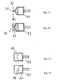
- FIG. 3 schematically shows a non-inventive pulsator 1 for a milking device for milking an animal, in particular a cow, with a device by means of which at least the time course of the evacuation phase and / or the ventilation phase is adjustable.
- the device has a valve 9.
- the valve comprises a chamber 10 in which a valve body 11 is movably arranged.
- the valve body 11 can be attached to a first valve seat 12 or to a second valve seat 13.
- valve body 11 rests on the first valve seat 12, so that a connection of a channel 14 with the chamber 10 is interrupted.
- the channel 14 is connected via a line, not shown, with a vacuum source (vacuum source).
- vacuum source vacuum source
- the second valve seat 13 opens a channel 15 which communicates with the ambient atmosphere.
- the chamber 10 communicates via a channel 16 with the milking machine.
- valve body has reached an end position in which a connection of a milking cup or the milking unit via the channel 16, the chamber 10 and the channel 15 is present with the ambient atmosphere, so that a ventilation of the pulse space of the milking cup takes place.
- the valve body 11 is preferably placed in a specific floating position, ie in a position between its end positions, as shown in the FIG. 3 is shown.
- the valve body passes out of the floating position, the area between the end positions.
- the position of the valve body 11 or the valve cross-section results from the driving forces and moments and the opposing forces acting in the valve due to friction, weight, spring forces or other restoring forces or the like, and in particular the pressure in the valve. Therefore, there is a continuous relationship between control force / torque and valve cross-section. This is reflected in a valve characteristic.
- the control of the valve 9 takes place in dependence on a valve characteristic, whereby the course of the evacuation phase and / or the ventilation phase can be adjusted accordingly.
- the valve 9 is preferably an electromagnetic valve.
- the valve body can have permanent magnetic properties.
- the applied for the displacement of the valve body forces come from preferably two substantially axially behind one another arranged coils with opposite winding sense, which form electromagnets with opposite poles in current flow.
- the valve body can move axially along the coil axes, up to the first and the second valve seat.
- FIG. 5 shows a non-inventive pulsator 20 for a milking device for milking an animal, in particular a cow, wherein the pulsator comprises means by which at least the time course of the evacuation phase and / or the ventilation phase is adjustable.
- the device comprises a pilot valve 21 and a main valve 20.
- the pilot valve 21 has a chamber 23 in which a valve body 24 is movable back and forth between two end positions.
- the channel 25 is connected via a non-illustrated connection of the pulsator with a vacuum source.
- the mouth of the channel 25 is closed by the valve body 24.
- the mouth of the channel 27 is closed in another position of the valve body 24.
- the channel 27 connects the chamber 23 with the ambient atmosphere.
- the chamber 23 is connected to an upper space 31.
- the upper space 31 is formed in a housing 28. This is limited by the housing and by a diaphragm 29 which is elastic. With the membrane 29, a valve body 30 of the main valve 22 is connected.
- the valve body has sealing surfaces 32, 33. The valve surface 32 is for abutment against the valve seat 34 while the sealing surface 33 is attachable to the valve seat 35.
- the valve body 30 is arranged in a chamber 36.
- the chamber 36 communicates via a passage 37 in communication with a lower space 38 bounded by the housing 28 and the diaphragm 29.
- the chamber 36 opens a channel 39 which is connectable to the pulse space of a milking cup.
- the chamber 36 of the main valve 22 is also connectable to a vacuum source via the channel 40.
- an opening 41 is provided, so that the lower space 38 is in communication with the ambient atmosphere.
- the pilot valve 21 is preferably a valve which is operated largely binary. If the valve body 24 of the pilot valve 21 is moved upward, it closes the mouth of the channel 27, so that the connection of the chamber 23 is interrupted with the ambient atmosphere. At the same time the mouth of the channel 25 is released. About the channel 25 and the channel 40 is formed within the chamber 23, a negative pressure, since the chamber 23 is now connected via the channel 25 and the channel 40 with a vacuum source. Due to the channel 26, which connects the chamber 23 with the upper space 31, created at the diaphragm 29, a pressure difference, since in the upper space 31, there is a lower pressure than in the lower chamber 38.
- the forces acting through the pressure difference on the Membranes 29 cause the diaphragm 29 to move upwards, ie in the direction of the upper space 31. Due to the rigid connection of the valve body 30 of the main valve 22 with the diaphragm, the valve body 30 is moved as far in the direction of the valve seat 35 until the valve face 33 rests on the valve seat 35. The speed at which the valve body 30 moves in the direction of the valve seat 35 is also dependent on the volume of the upper space 31.
- valve body 30 During the movement of the valve body 30, the free flow cross-section for the connection of the channels 39 and 40 will increase, while the connecting cross-section between the lower space 38 and the channel 39 decreases. In its end position, the valve face 33 of the valve body 30 bears against the valve seat 35.
- the pilot valve 21 is activated.
- the valve body 24 of the pilot valve 21 is moved such that the valve body closes the mouth of the channel 25 in the space 23 of the pilot valve 21.
- the mouth of the channel 27 is opened, so that a connection between the atmosphere of the environment and the chamber 23 is established.
- the valve body moves away from the valve seat 35 in the direction of the valve seat 34, so that the milking over the channel 39, the chamber 36 of the main valve and the passage 37 comes into contact with the ambient atmosphere, whereby aeration of the pulse space of the Melkzeugs takes place.
- FIG. 6 shows a further non-inventive pulsator.
- the pulsator 50 differs from that in the FIG. 5 represented pulsator 20 characterized in that in the channel 26, an element 51 is provided which forms a flow resistance. The time course of the evacuation phase is dependent on the element 51.
- FIGS. 7 to 10 is another, non-inventive pulsator 70 is shown.
- the pulsator 70 is in Fig. 7 shown in section. He is in the ventilation phase. This is a slide valve. The slider 73 releases the opening 74 in this position. The tip 76 of the slider is triangular. At the Change from the in FIGS. 8 and 10 shown evacuation phase in the ventilation phase, the slider 73 in the illustration of the Fig. 7 to 10 pulled to the right against the biasing force of the spring 75. In this case, the triangular tip 76 of the slide 73 initially releases small areas of the opening 74 next to the foremost point 76 for ventilation and an initially small air flow can flow to the pulse space of the teat cup.
- the released portion of the opening With increasing travel towards the end stop, the released portion of the opening becomes larger and the rate of pressure increase increases compared to a conventional system in which the entire cross section is opened simultaneously or nearly simultaneously because of the time required for a conventional slide to open is in the range of a few milliseconds.
- the slider 73 is held by appropriate pulses in a floating position and releases the opening only slowly and controlled.
- a solenoid (not shown) can be provided, which can be kept in a floating position particularly simple by electrical impulses.
- the evacuation port 78 is also triangular and in FIGS. 8 and 10 dashed lines. If, starting from the d-phase, the pulse space is to be evacuated again, the a-phase, ie the evacuation phase, is initiated. For this purpose, the slider 73 from the in FIGS. 7 and 9 shown position moves to the left, so that the vacuum supply line 72 is connected via the slider 73 with the pulse chamber terminal 71 of the milking cup. In turn, the straight edge of the slider 73 cooperates with the tip of the triangular evacuation port 78. First, a small cross-section is now released. As the travel increases, the cross section becomes larger and the evacuation speed increases.
- the control can be done floating in all these cases. Or the slide is moved accordingly slow. This can be done, for example, by a suitable vacuum on the control vacuum line 77.
- FIG. 11 shows a pulsator according to the invention.
- FIGS. 12 to 14 Further Ausftihrungsbei admir of sliding pulsators 73 are shown.
- the slider 81 off Fig. 11 has a triangular tip, as the slider 73 from Fig. 7 , After the pulsator Fig. 11 but are three ventilation openings 91 and 92 provided in the slide plate.
- the two laterally arranged from the central axis of symmetry ventilation opening 92 are initially opened and a relatively small air flow can enter the channel 71. After further displacement, the opening 91 is released and the pressure change rate increases.
- the slider 82 after Fig. 12 has a rectangular projection at the front, so that when pulling back the lateral areas are released, before finally the whole - here as in Fig. 7 rectangular designed vent 93 - is released.
- slides 84 and 85 are provided for control of the evacuation phase.
- the cavity 86 is designed triangular in the direction of the pulse space line 71 to the teat cup and the slider 85 has in the front region of the cavity 87 has a narrow tail 88, which first comes into contact with the pulse space line 71.
- two and more different speeds of a pressure change phase can thus be set according to the invention.
Landscapes
- Life Sciences & Earth Sciences (AREA)
- Animal Husbandry (AREA)
- Environmental Sciences (AREA)
- External Artificial Organs (AREA)
- Housing For Livestock And Birds (AREA)
Abstract
Description
Der Gegenstand der Erfindung bezieht sich auf ein Verfahren zum maschinellen Melken eines Tieres, beispielsweise einer Kuh, beim welchen ein pulsierender Unterdruck mit aufeinander folgenden Evakuierungsphasen und Belüftungsphasen in einem Melkbecher über einen zugeordneten Pulsator erzeugt wird, sowie auf einen Pulsator. Obwohl die Erfindung im folgenden mit Bezug auf die Anwendung beim Melken von Kühen beschrieben wird, ist es aber ebenso möglich, die Erfindung beim Melken von anderen milchabgebenden Tieren, wie z.B. Ziegen, Schafen, Büffeln, Lamas, Kamelen, Dromedaren, Yaks etc. einzusetzen.The object of the invention relates to a method for the automatic milking of an animal, for example a cow, in which a pulsating negative pressure with successive evacuation phases and ventilation phases is generated in a teat cup via an associated pulsator, as well as on a pulsator. Although the invention will be described below with reference to milking cows, it is also possible to use the invention in milking other milk-giving animals, e.g. Goats, sheep, buffalo, llamas, camels, dromedaries, yaks, etc.
Verfahren sowie Vorrichtungen, bei denen ein pulsierender Unterdruck mit abwechselnd aufeinander folgenden Saugphasen und Entlastungsphasen in einem Melkbecher eines Melkzeugs erzeugt wird, um ein maschinelles Melken von Tieren zu ermöglichen, sind an sich bekannt.Methods and devices in which a pulsating negative pressure with alternately successive suction phases and relief phases in a milking cup of a milking machine is generated in order to enable a machine milking animals are known per se.
Bei derartigen Verfahren bzw. Vorrichtungen wird insbesondere nach Durchführung einer Stimulationsphase ein im wesentlichen gleichmäßig pulsierender Unterdruck im Pulsraum eines Melkbechers erzeugt, um ein im Zitzenraum im Inneren des Melkbechers vorgesehenes Zitzengummi in eine pulsierende Melkbewegung zu versetzen.In such methods or devices, in particular after a stimulation phase has been carried out, a substantially uniformly pulsating negative pressure is generated in the pulse space of a milking cup in order to set a teat cup provided in the teat space in the interior of the milking cup into a pulsating milking movement.
Hierzu umfasst die Vakuumeinrichtung einer Saugmelkanlage eine Vakuumpumpe, ein Vakuumventil, Druckverbindungsleitungen zu den Melkbechern sowie eine Steuereinrichtung zur Erzeugung von Ventilsteuerimpulsen. Durch die Steuereinrichtung wird ein Ventilöffnungsimpuls und Ventilschließungsimpuls erzeugt. Die Vakuumpumpe der Anlage erzeugt einen im wesentlichen konstanten Unterdruck, der etwa dem Pulsationsdruck entspricht.For this purpose, the vacuum device of a Saugmelkanlage comprises a vacuum pump, a vacuum valve, pressure connection lines to the teat cups and a control device for generating valve control pulses. By the control device, a valve opening pulse and valve closing pulse is generated. The vacuum pump of the system generates a substantially constant negative pressure, which corresponds approximately to the pulsation pressure.
In fest vorgegebenen Zeitabständen werden von der Steuereinrichtung Steuersignale zum Öffnen des Ventils der Vakuumeinrichtung erzeugt, so dass im Melkbecherzwischenraum im wesentlichen abrupt ein Unterdruck aufgebaut wird. Dieses Vakuum wird über eine fest vorgegebene Zeitdauer aufrechterhalten. Ebenso wie beim Vakuumaufbau wird nach Erhalt eines weiteren Steuerimpulses der Druck im Melbecherzwischenraum plötzlich abgebaut, indem der Pulsraum wieder evakuiert wird. Innerhalb einer voreingestellten Pulsationsperiode wird dieser Vorgang gleichmäßig wiederholt. Da sowohl der Druckaufbau als auch der Druckabbau im wesentlichen abrupt erfolgen, d. h. unter Vernachlässigung der Trägheit des Systems und der Größe von Anlagenteilen, die mit ihrem Volumen an der Vakuumbildung beteiligt sind, ist die Zitze eines Tieres beispielsweise in der Belüftungsphase einer schlagartigen Belastung ausgesetzt, weil das Zitzengummi schlagartig einfaltet und auf die empfindliche Zitze aufschlägt. Dies kann während eines Melkvorgangs zu einem unangenehmen Gefühl für das Tier führten. In Reaktion auf dieses Gefühl kann es zu einer gestörten oder sogar zu einer unvollständigen Milchabgabe durch das Tier kommen.At fixed predetermined time intervals, the control device generates control signals for opening the valve of the vacuum device, so that a negative pressure is built up substantially abruptly in the teat cup space. This vacuum will maintained over a fixed period of time. As in the case of vacuum build-up, after receiving a further control pulse, the pressure in the milking-chamber gap is suddenly reduced by evacuating the pulse space again. Within a preset pulsation period, this process is repeated evenly. Since both the pressure build-up and the pressure release are substantially abrupt, ie neglecting the inertia of the system and the size of parts of the plant involved in the vacuum formation, the teat of an animal is exposed to a sudden load, for example in the ventilation phase, because the teat liner suddenly folds up and hits the sensitive teat. This can lead to an unpleasant sensation for the animal during a milking process. In response to this sensation, disturbed or even incomplete delivery of the milk by the animal may occur.
Diese Problematik sowie weitere Nachteile, die sich durch die schlagartige Veränderung des Druckes ergeben, sind bekannt. Es sind auch bereits Lösungsvorschläge unterbreitet worden. Durch die
Ferner ist durch die
Aus der
Das Patent
Hiervon ausgehend liegt der vorliegenden Erfindung die Zielsetzung zugrunde, ein Verfahren sowie eine Vorrichtung anzugeben, durch das bzw. die ein schonenderes Melken eines Tieres bei akzeptabler Geschwindigkeit ermöglicht wird.Proceeding from this, the present invention is based on the object of specifying a method and a device by means of which a more gentle milking of an animal at an acceptable speed is made possible.
Diese Zielsetzung wird durch das erfindungsgemäße Verfahren mit den Merkmalen des Anspruchs 1 bzw. durch die erfindungsgemäße Vorrichtung mit den Merkmalen nach Anspruch 11 erreicht. Vorteilhafte Weiterbildungen und Ausgestaltungen der Erfindung sind Gegenstand der jeweiligen Unteransprüche.This object is achieved by the method according to the invention with the features of
Bei dem erfindungsgemäßen Verfahren zum maschinellen Melken eines Tieres, beispielsweise einer Kuh, wird ein pulsierender Unterdruck in einem Pulsraum eines Melkbechers erzeugt, indem in den Druckänderungsphasen der Unterdruck in dem Pulsraum verändert wird. Dabei wird der Druckverlauf während wenigstens einer Druckänderungsphase über ein Verstellen einer Stelleinheit in wenigstens zwei Geschwindigkeiten gesteuert. Das Verfahren zeichnet sich dadurch aus, dass der zeitliche Verlauf der Evakuierungsphase und/oder
der Belüftungsphase in Abhängigkeit von einer Ventilkennlinie eines Ventils mit wenigstens zwei Ventilöffnungen des Pulsators eingestellt wird, wobei der Ventilquerschnitt des Ventils des Pulsators verändert wird, um die Geschwindigkeit während der Druckänderungsphase zu verändern.In the method according to the invention for automatically milking an animal, for example a cow, a pulsating negative pressure is generated in a pulse space of a milking cup by changing the negative pressure in the pulse space in the pressure change phases. In this case, the pressure profile is controlled during at least one pressure change phase via an adjustment of an actuating unit in at least two speeds. The method is characterized in that the time course of the evacuation phase and / or
the ventilation phase is adjusted in dependence on a valve characteristic of a valve having at least two valve openings of the pulsator, wherein the valve cross-section of the valve of the pulsator is changed to change the speed during the pressure change phase.
In der Ventillcennlinie können unterschiedliche Einflussfaktoren berücksichtigt werden, die einen Einfluss auf das Öffnen bzw. Schließen des Ventils haben. Insbesondere werden in der Ventilkennlinie die Gegenkräfte berücksichtigt, die aufgrund von Reibung, Gewichtskraft, Federkräften oder anderen Rückstellkräften oder dergleichen eine Auswirkung auf das Ansprechverhalten des Ventils haben.In the Ventillcennlinie different influencing factors can be considered, which have an influence on the opening or closing of the valve. In particular, in the valve characteristic, the counter forces are taken into account, which have an effect on the response of the valve due to friction, weight, spring forces or other restoring forces or the like.
Unter einer Druckänderungsphase kann im Sinne dieser Anmeldung die Evakuierungsphase und/oder auch die Belüftungsphase eines Pulsatorzyklus verstanden werden.In the context of this application, a change in pressure phase can be understood to mean the evacuation phase and / or also the ventilation phase of a pulsator cycle.
Der Druckverlauf ist die Geschwindigkeit einer Druckänderung mit der Zeit. Schnellere Druckänderungen erzeugen steilere Druckverläufe als langsamere Druckänderungen mit flacheren Druckverläufen.The pressure curve is the speed of a pressure change over time. Faster pressure changes produce steeper pressure gradients than slower pressure changes with flatter pressure gradients.
Es können auch zwei (oder mehr) unterschiedliche Geschwindigkeitsstufen vorgesehen sein.There may also be two (or more) different speed levels.
Es wird hier ein solches Steuern durchgeführt, dass die Geschwindigkeitsänderung von einer ersten auf eine zweite Geschwindigkeit durch aktive Steuerungsmaßnahmen bewirkt wird.Here, such control is performed that the speed change from a first to a second speed is effected by active control measures.
Die erfindungsgemäße Verfahrensführung hat viele Vorteile. Durch die zwei Geschwindigkeiten, mit denen eine Druckänderung bewirkbar ist, kann einerseits ein ausreichend schnelles Melken erzielt werden, während andererseits schonend mit der Zitze umgegangen wird.The process control according to the invention has many advantages. Due to the two speeds, with which a pressure change can be effected, on the one hand a sufficiently fast milking can be achieved while, on the other hand, the teat is gently treated.
Die Belüftungsphase kann in zwei Abschnitte eingeteilt werden. In dem ersten Abschnitt kann dann der Druckaufbau mit einer geringeren Geschwindigkeit erfolgen als in dem zweitem Abschnitt.The ventilation phase can be divided into two sections. In the first section, the pressure build-up can then take place at a lower speed than in the second section.
Der pulsierende Unterdruck wird über einen Pulsator eingestellt, wobei der Druckverlauf während der Druckänderungsphase(n) vorzugsweise über ein Verstellen einer Stelleinrichtung gesteuert wird. Die Stelleinrichtung kann z.B. elektrisch oder auch mechanisch gesteuert werden und sie kann eine mechanische Stellgröße verändern, wie z.B. einen Strömungsquerschnitt.The pulsating negative pressure is adjusted via a pulsator, wherein the pressure profile during the pressure change phase (s) is preferably controlled by means of an adjustment of an actuating device. The actuator may e.g. electrically or mechanically controlled and it can change a mechanical manipulated variable, such. a flow cross-section.
Während der Evakuierungsphase steigt das Vakuum im Pulsraum des Zitzenbechers auf das höchste Vakuum im Pulsraum an. Die Belüftungsphase wird als die Zeitspanne bezeichnet, in der die Vakuumhöhe vom höchsten Wert im Pulsraum auf einen vorgegebenen niedrigsten Vakuumwert abfällt.During the evacuation phase, the vacuum in the pulse space of the teat cup rises to the highest vacuum in the pulse space. The aeration phase is referred to as the period in which the vacuum level drops from the highest value in the pulse space to a predetermined lowest vacuum value.
Der Erfindung liegt die prinzipielle Überlegung zugrunde, dass, der zeitliche Verlauf der Evakuierungsphase und/oder der Belüftungsphase mittels zweier Druckänderungsgeschwindigkeiten eingestellt wird. Durch diese Möglichkeit wird der Druckabfall bzw. -anstieg im Pulsraum einerseits schnell und andererseits langsam und schonend eingestellt, so dass ein schonendes und dennoch schnelles Melken ermöglicht wird. Der jeweilige Zeitraum, den eine Druckänderungsphase benötigt, wird im Vergleich zum Stand der Technik nur unwesentlich verlängert. Bei einer entsprechend größeren Belüftungsgeschwindigkeit nach Anlegen des Zitzengummis an die Zitze, die dann ja unschädlich ist, kann der Zeitraum gleich lang bleiben.The invention is based on the basic idea that the time course of the evacuation phase and / or the aeration phase is set by means of two pressure change rates. By this possibility, the pressure drop or increase in the pulse space on the one hand fast and on the other hand slow and gently adjusted, so that a gentle, yet fast milking is possible. The respective period required by a pressure change phase is only marginally longer than in the prior art. At a correspondingly greater ventilation speed after applying the teatcup liner to the teat, which is then harmless, the period can remain the same length.
Der Verlauf des Druckabfalls bzw. Druckanstiegs hat Auswirkung auf die Bewegungsgeschwindigkeit des Zitzengummis. In Abhängigkeit davon, wie der Verlauf der Evakuierungsphase und/oder der Belüftungsphase eingestellt wird, wird eine entsprechende Öffnungs- und/oder Schließgeschwindigkeit des Zitzengummis erzielt. Mit anderen Worten zwischen der Öffnungs- bzw. der Schließgeschwindigkeit des Zitzengummis und der Belüftungsphase bzw. der Evakuierungsphase wird ein Zusammenhang, wie z. B. eine Korrelation hergestellt, die in einer vorteilhaften Weise für den Melkvorgang genutzt wird. In Abkehr von den bisher bekannten Verfahren wird hierdurch das Zitzengummi nicht mehr schlagartig sondern für das Tier verträglicher, angenehmer zur Anlage an die Zitze gebracht.The course of the pressure drop or pressure increase has an effect on the speed of movement of the teatcup liner. Depending on how the course of the evacuation phase and / or the ventilation phase is set, a corresponding opening and / or closing speed of the teatcup liner is achieved. In other words, between the opening and the closing speed of the teatcup liner and the ventilation phase or the evacuation phase is a relationship such. B. a correlation produced, which is used in an advantageous manner for the milking process. In departure from the previously known method, the teatcup liner is thus no longer abruptly but more compatible with the animal, more pleasant to plant on the teat.
Vorzugsweise wird der Druckverlauf wenigstens während der Belüftungsphase gesteuert, um ein Schlagen des Zitzengummis auf die Zitze zu verhindern. Außerdem oder anstatt dessen kann der Druckverlauf auch wenigstens während der Evakuierungsphase gesteuert werden.Preferably, the pressure profile is controlled at least during the venting phase in order to prevent the teatcup from hitting the teat. In addition or instead, the pressure profile can also be controlled at least during the evacuation phase.
Es wird die Möglichkeit geschaffen, das Zitzengummi schonend an die Zitze anzubringen. Darüber hinaus wird durch diese Maßnahme in der Evakuierungsphase ein bei sehr schneller Bewegung des Zitzengummis auftretender Rücksprayeffekt der Milch in Richtung der Zitze reduziert und kann bei entsprechender Anpassung weitgehend oder sogar weitestgehend vermieden werden. Die Einstellbarkeit der Druckverläufe, insbesondere deren Dynamik in der Evakuierungs- und in der Belüftungsphase ermöglicht auch eine wesentliche Anpassung an unterschiedliche Zitzengummi, Melkbecher und Melkzeuge wobei unter Umständen zusätzliche mechanische Maßnahmen unterbleiben können.It is created the possibility to attach the teatcup gum gently to the teat. In addition, by this measure in the evacuation phase occurring during very rapid movement of the teatcup liner backspray effect of the milk is reduced in the direction of the teat and can be largely or even largely avoided with appropriate adjustment. The adjustability of the pressure gradients, in particular their dynamics in the evacuation and in the ventilation phase also allows a substantial adaptation to different teatcup liner, milking cups and milking clusters may possibly be omitted additional mechanical measures.
Es ist mit der erfindungsgemäßen Verfahrensführung beispielsweise möglich, die Bewegung des Zitzengummis bis zum Erreichen einer bestimmten Stellung des Zitzengummis mit einer relativ geringen Geschwindigkeit zu verändern und nach Erreichen dieser Stellung bzw. Verformung das Zitzengummi mit einer hohen Geschwindigkeit zu bewegen. Und umgekehrt.It is possible with the process control according to the invention, for example, to change the movement of the teatcup liner until reaching a certain position of the teatcup liner at a relatively low speed and to move the teatcup liner at a high speed after reaching this position or deformation. And vice versa.
Vorzugsweise verläuft die Geschwindigkeit der Druckänderung innerhalb eines Zeitabschnittes im wesentlichen kontinuierlich. Es können auch mehr als zwei Zeitabschnitte und/oder mehr als zwei Geschwindigkeiten der Druckänderung vorgesehen sein, zur jeweils drei. Dann kann der Druck zunächst schneller verändert werden, bis etwa der Einfaltdruck des Zitzengummis erreicht wird, dann langsamer bis das Zitzengummi schonend geschlossen oder geöffnet wurde, um dann wieder schneller zu schließen bzw. zu öffnen.Preferably, the rate of pressure change within a period of time is substantially continuous. It can also be provided more than two time periods and / or more than two speeds of pressure change, for each three. Then, the pressure can be changed faster first, until about the folding pressure of the teatcup liner is reached, then slower until the teatcup liner has been gently closed or opened, then again close faster or open.
Nach einer weiteren vorteilhaften Ausgestaltung des Verfahrens wird vorgeschlagen, dass der zeitliche Verlauf wenigstens einer Druckänderungsphase, nämlich der Evakuierungsphase und/oder der Belüftungsphase zumindest innerhalb eines Abschnittes diskontinuierlich ist. Durch eine kontinuierliche und/oder diskontinuierliche Einstellbarkeit des zeitlichen Verlaufes der Evakuierungsphase und/oder der Belüftungsphase wird die Möglichkeit geschaffen, die Bewegung des Zitzengummis in vorteilhafter Weise zu beeinflussen.According to a further advantageous embodiment of the method, it is proposed that the time profile of at least one pressure change phase, namely the evacuation phase and / or the ventilation phase is discontinuous at least within a section. By a continuous and / or discontinuous adjustability of the time course of the evacuation phase and / or the ventilation phase, the possibility is created to influence the movement of the teatcup liner in an advantageous manner.
Vorzugsweise wird der Druckverlauf in einem ersten Abschnitt und in einem Folgeabschnitt der Belüftungsphase derart gesteuert, dass der Druckverlauf in dem ersten Abschnitt flacher ist als in dem Folgeabschnitt und besonders bevorzugt erheblich flacher.Preferably, the pressure profile in a first section and in a following section of the aeration phase is controlled such that the pressure profile in the first section is flatter than in the following section, and particularly preferably considerably flatter.
In dem ersten Abschnitt einer Belüftungsphase wird dann der Druck im Pulsraum bis auf etwa den Einfaltdruck erhöht. Das Zitzengummi legt sich langsam an und ein unangenehmes Schlagen auf die Zitze wird deutlich reduziert oder sogar verhindert. Danach erfolgt der Druckaufbau schneller und der Druckverlauf ist steiler. Auch hier sind drei oder mehr Abschnitte möglich, wobei ein vorzugsweise ein mittlerer Abschnitt mit geringerer Druckänderung vorgesehen ist, in dem sich das Zitzengummi an die Zitze anlegt. Nach dem Anlegen wird der Druck vorzugsweise schneller erhöht als im Stand der Technik.In the first section of a ventilation phase, the pressure in the pulse space is then increased to about the folding-in pressure. The teatcup liner slowly settles and an unpleasant beating on the teat is significantly reduced or even prevented. Thereafter, the pressure build-up is faster and the pressure curve is steeper. Again, there are three or more sections possible, with one preferably a medium section with a smaller pressure change is provided, in which the teat rubber is applied to the teat. After application, the pressure is preferably increased faster than in the prior art.
Vorzugsweise wird der Druckverlauf in einem ersten Abschnitt und in einem Folgeabschnitt der Evakuierungsphase derart gesteuert, dass der Druckverlauf in dem ersten Abschnitt flacher ist als in dem Folgeabschnitt und vorzugsweise erheblich flacher.Preferably, the pressure profile in a first section and in a subsequent section of the evacuation phase is controlled such that the pressure profile in the first section is flatter than in the following section, and preferably considerably shallower.
Im ersten Abschnitt wird der Druck reduziert, bis die Druckdifferenz zwischen Puls- und Zitzenraum etwa dem Einfaltdruck entsprich, vorzugsweise etwas kleiner ist, so dass das Zitzengummi abgehoben hat. Danach wird die Geschwindigkeit der Druckänderung erhöht und der Druckverlauf steiler, um nach dem langsamen Abheben einen schnelleren weiteren Verlauf zu gewährleisten. Das verhindert das sogenannte und unerwünschte Rücksprayen von Milch auf die Zitze. Auch hier sind drei Abschnitte möglich, wobei in einem ersten und dritten Abschnitt die Geschwindigkeit hoch ist und im zweiten Abschnitt in einem Druckbereich in der Nähe des Einfaltdruckes die Geschwindigkeit reduziert wird.In the first section, the pressure is reduced until the pressure difference between the pulse chamber and the teat chamber corresponds approximately to the folding-in pressure, and is preferably somewhat smaller, so that the teatcup liner has lifted off. Thereafter, the speed of the pressure change is increased and the pressure curve becomes steeper, to ensure a quicker progression after the slow lift off. This prevents the so-called and unwanted back-spraying of milk on the teat. Here, too, three sections are possible, wherein in a first and third section, the speed is high and in the second section in a pressure range in the vicinity of the fold-in speed is reduced.
Vorzugsweise wird von dem ersten (flachere Druckänderung) zu dem zweiten Abschnitt (steilere Druckänderung) umgeschaltet, wenn der Druck im Pulsraum in einem Bereich eines Einfaltdruckes des Zitzengummis liegt.It is preferable to switch from the first (shallower pressure change) to the second portion (steeper pressure change) when the pressure in the pulse space is within a range of a tuck-in pressure of the teatcup liner.
Beispielsweise kann bei einem vorbestimmten Umschaltdruck umgeschaltet werden, wobei in einem ersten Abschnitt der Belüftungsphase bis zum Erreichen des Umschaltdruckes die Geschwindigkeit der Druckänderung geringer ist und anschließend schneller wird, nachdem das Zitzengummi sich an die Zitze angelegt hat.For example, can be switched at a predetermined switching pressure, wherein in a first portion of the aeration phase until reaching the switching pressure, the rate of pressure change is lower and then faster after the teatcup liner has been applied to the teat.
Der Umschaltdruck ist vorzugsweise etwa der jeweilige Einfaltdruck des Zitzengummis, also der Druck, bei dem der Druckunterschied zwischen Puls- und Zitzenraum etwa dem Einfaltdruck des Zitzengummis entspricht. Der vorbestimmte Umschaltdruck ist vorzugsweise einstellbar.The switchover pressure is preferably approximately the respective fold-in pressure of the teatcup liner, that is to say the pressure at which the pressure difference between the pulse and teat chambers corresponds approximately to the fold-in pressure of the teatcup liner. The predetermined one Switching pressure is preferably adjustable.
In der Belüftungsphase (a-Phase) wird vorzugsweise bei einer Druckdifferenz etwas größer als Einfaltdruck von der geringeren Druckänderungsgeschwindigkeit auf eine hohe Druckänderungsgeschwindigkeit umgeschaltet, um ein Einfalten des Zitzengummis mit hoher Geschwindigkeit zu verhindern.In the aeration phase (a-phase), it is preferable that, at a pressure difference, slightly larger than a folding pressure is switched from the lower pressure changing speed to a high pressure changing speed to prevent high-speed folding of the teatcup liner.
In der Evakuierungsphase wird vorzugsweise bei einer Druckdifferenz etwas größer als Einfaltdruck von der niedrigen Druckänderungsgeschwindigkeit auf eine hohe Druckänderungsgeschwindigkeit umgeschaltet, um ein Öffnen des Zitzengummis mit hoher Geschwindigkeit zu verhindern.In the evacuation phase, it is preferable that, at a pressure difference, slightly larger than a folding pressure is switched from the low pressure changing speed to a high pressure changing speed to prevent opening of the teatcup liner at a high speed.
Durch die erfindungsgemäße Verfahrensführung lassen sich Pulsatoren auf einen Melkbecher, ein Melkzeug oder mehrere angeschlossene Melkzeuge, Bio-Melker, unterschiedliche Schlauchlängen und -querschnitte, sowie Volumina im Melkbecher und Melkzeug anpassen. Die Qualität der Pulsation kann damit auch softwaretechnisch kontrolliert werden. Insbesondere mit einer elektronisch nachgeführten Kontrolle der Pulsationsqualität ist es damit auch möglich, die dynamischen Verläufe der Evakuierungsphase bzw. der Belüftungsphase zu kontrollieren.The method according to the invention makes it possible to adapt pulsators to a milking cup, a milking machine or several connected milking devices, organic milking devices, different tube lengths and cross sections, as well as volumes in the milking cup and milking cluster. The quality of the pulsation can thus also be controlled by software. In particular, with an electronically tracked control of pulsation quality, it is thus also possible to control the dynamic progress of the evacuation phase or the aeration phase.
Gemäß einer vorteilhaften Ausgestaltung des Verfahrens wird vorgeschlagen, dass die Dauer der Evakuierungsphase und/oder der Belüftungsphase eingestellt wird. Der Verlauf der Druckänderung während der Dauer der Evakuierungsphase und/oder der Belüftungsphase kann unterschiedlich sein. Es besteht auch die Möglichkeit, innerhalb der vorgegebenen Dauer den Verlauf entsprechend den technischen und/oder physiologischen Gegebenheiten der Anlage bzw. des Tieres anzupassen. Das erfindungsgemäße Verfahren kann auch in Verbindung mit modernen Steuereinrichtungen oder Steuersystemen in Form z.B. eines Herdenmanagement-Systems durchgeführt werden. Verfügt ein solches Steuersystem über tierindividuelle Daten und ist bekannt, welches Tier einem Melkvorgang unterzogen werden soll, so kann der Verlauf der Evakuierungsphase und/oder der Belüftungsphase auch tierindividuell eingestellt werden. Insbesondere die Geschwindigkeiten können vorgegeben bzw. individuell angepasst sein.According to an advantageous embodiment of the method, it is proposed that the duration of the evacuation phase and / or the aeration phase is set. The course of the pressure change during the duration of the evacuation phase and / or the aeration phase can be different. It is also possible to adjust the course according to the technical and / or physiological conditions of the plant or the animal within the specified duration. The method according to the invention can also be carried out in conjunction with modern control devices or control systems in the form of, for example, a herd management system. If such a control system has animal-specific data and if it is known which animal is to undergo milking, the course of the evacuation phase can take place and / or the ventilation phase are also set animal-specific. In particular, the speeds may be predetermined or customized.
Die unterschiedlichen Geschwindigkeiten des Druckverlaufes können in Abhängigkeit vom Einfaltdruck des zum Melken vorgesehenen Zitzengummis ausgewählt werden. Ebenso sollte der für die Öffnung des Zitzengummis relevante Bereich der Phase so gestaltet werden, dass die daraus resultierende Volumenvergrößerung innerhalb des Melkbechers nicht zu einem Rücksprayeffekt in Richtung der Zitze führt. Auch hierbei kann durch eine Unterteilung des Druckanstiegs in mindestens zwei oder drei oder mehr Bereiche speziell der für das Öffnen verantwortliche Zeitabschnitt gestaltet werden.The different speeds of the pressure curve can be selected depending on the fold-in pressure of the teatcup liner intended for milking. Likewise, the area of the phase relevant to the opening of the teatcup liner should be designed such that the resulting increase in volume within the teat cup does not result in a backspray effect in the direction of the teat. Again, by dividing the pressure increase into at least two or three or more areas, the time period responsible for the opening can be designed specifically.
Vorzugsweise kann z.B. zunächst ein erster Teil des Strömungsquerschnittes im Pulsatorventil geöffnet werden und später ein weiterer Teil dazu. Damit ergibt sich eine variable Geschwindigkeit der Bewegung.Preferably, e.g. first, a first part of the flow cross-section are opened in the pulsator and later another part. This results in a variable speed of movement.
Es sind Pulsatoren bekannt, die einen unterschiedlichen Systemaufbau aufweisen. Aufgabe eines Pulsators ist es, Luft höheren oder niedrigeren Drucks über die Pulsationsschläuche an den oder die Melkbecher zu leiten, wobei dieser in Verbindung mit dem an der Zitzenspitze anliegendem Unterdruck und der atmosphärischen Außenluft zur Erzeugung einer Bewegung des Zitzengummis verwendet wird. Der Pulsator weist wenigstens ein Ventil auf.Pulsators are known which have a different system structure. The purpose of a pulsator is to direct air of higher or lower pressure to the milking cup (s) via the pulsation tubes, which is used in conjunction with the vacuum applied to the tip of the teat and the atmospheric outside air to produce movement of the teatcup liner. The pulsator has at least one valve.
Nach einer weiteren vorteilhaften Ausgestaltung des Verfahrens wird vorgeschlagen, dass der Strömungswiderstand zum Melkbecher hin verändert wird. Bevorzugt ist dabei eine Ausgestaltung, in der der freie Strömungsquerschnitt, insbesondere im Pulsschlauch, verändert wird.According to a further advantageous embodiment of the method is proposed that the flow resistance is changed to the milking cup. In this case, an embodiment in which the free flow cross section, in particular in the pulse tube, is changed, is preferred.
Erfindungsgemäß wird der Ventilquerschnitt eines Ventils des Pulsators verändert, um die Geschwindigkeit während einer Druckänderungsphase zu beeinflussen. Der Ventilquerschnitt bzw. der freie Strömungsquerschnitt eines Ventils kann dazu mehrstufig verändert werden.According to the invention, the valve cross-section of a valve of the pulsator is changed in order to influence the speed during a pressure change phase. The valve cross section or the free flow cross section of a valve can do this be changed in several stages.
Der Ventilquerschnitt kann auch kontinuierlich verändert werden, indem ein Schieber oder dergleichen über die Ventilöffnungen geschoben wird oder bei der Bewegung den freien Strömungsquerschnitt vergrößert. Vorzugsweise erfolgt eine Veränderung des Querschnittes (Vergrößerung oder Verkleinerung) dabei monoton und besonders bevorzugt streng monoton im mathematischen Sinne.The valve cross section can also be changed continuously by sliding a slide or the like over the valve openings or increasing the free flow cross section during the movement. Preferably, a change of the cross-section (enlargement or reduction) takes place monotonically and particularly preferably strictly monotonically in the mathematical sense.
Die Veränderung erfolgt über einen großen Teil der Zeitdauer der Druckänderungsphase. Der Ventilquerschnitt kann z.B. über 25 % oder 50 % der Zeitspanne verändert werden. Bei einer Belüftungs- und Evakuierungsphase im typischen Bereich von z.B. 100 oder z.B. 150 ms beträgt die Dauer der Veränderung dann z.B. 35, 50 oder 70 oder noch mehr Millisekunden. Bei zwei verschiedenen Geschwindigkeitsstufen hingegen beträgt das Verhältnis der beiden Stufen vorzugsweise im Bereich zwischen 1:4 und 4:1, besonders bevorzugt zwischen 1:2 und 2:1. Somit beträgt die Länge eines Abschnittes bei zwei Geschwindigkeitsstufen etwa die Hälfte der Dauer der jeweiligen Druckänderungsphase.The change takes place over a large part of the duration of the pressure change phase. The valve cross section may e.g. be changed over 25% or 50% of the time span. In a venting and evacuation phase in the typical range of e.g. 100 or e.g. 150 ms, the duration of the change is then e.g. 35, 50 or 70 or even more milliseconds. In contrast, at two different speed levels, the ratio of the two stages is preferably in the range between 1: 4 and 4: 1, more preferably between 1: 2 and 2: 1. Thus, the length of a section at two speed levels is about half the duration of the respective pressure change phase.
In einer anderen bevorzugten Weiterbildung wird das Pulsatorventil in wenigstens einem Abschnitt einer Druckänderungsphase in einer Schwimmstellung gehalten, indem entsprechende Steuerimpulse auf das Ventil gegeben werden. Die schwimmende Ansteuerung erfolgt grundsätzlich so, wie aus dem Stand der Technik bekannt.In another preferred embodiment, the pulsator valve is held in at least a portion of a pressure change phase in a floating position by appropriate control pulses are applied to the valve. The floating control is basically as known from the prior art.
Vorzugsweise wird das Pulsatorventil in wenigstens einem Abschnitt einer Druckänderungsphase in einer variablen Schwimmstellung gehalten. Eine zeitlich variable Schwimmstellung ist auch bevorzugt, bei der mit zunehmender Zeit der Öffnungsquerschnitt vergrößert oder verkleinert wird.Preferably, the pulsator valve is held in a variable float position in at least a portion of a pressure change phase. A variable-time floating position is also preferred in which the opening cross-section is increased or decreased with increasing time.
Vorzugsweise wird der Druck im Pulsraum erfasst und bildet vorzugsweise ein Eingangssignal einer Baueinheit, die ein Ausgangssignal liefert, durch welches der Pulsator und/oder ein Strömungswiderstand betätigt wird.Preferably, the pressure in the pulse space is detected and preferably forms an input signal of a structural unit, which supplies an output signal, by which the pulsator and / or a flow resistance is actuated.
Durch eine angepasste Steuerung wird nunmehr lediglich in den Bewegungszeiträumen des Zitzengummis die Druckwechselgeschwindigkeit verändert, damit die Bewegungsgeschwindigkeit des Zitzengummis reduziert und nachdem sich das Zitzengummi geschlossen hat, auf eine größere, vorzugsweise maximale, Druckwechselgeschwindigkeit gesteuert wird, damit die eigentliche Druckänderangsphasen insgesamt gleich lang bleiben, wie im Stand der Technik. Auch eine Verkürzung der Druckänderungsphasen ist möglich.By an adapted control now the pressure change speed is changed only in the movement periods of the teatcup liner so that the speed of movement of the teatcup liner is reduced and after the teatcup liner has closed is controlled to a larger, preferably maximum, rate of pressure change so that the actual pressure change phases remain the same length, as in the prior art. A shortening of the pressure change phases is possible.
Die Evakuierungsphase der Pulsation wird vorzugsweise in mindestens zwei Bereiche unterteilt, wobei der Druckabfall pro Zeiteinheit unterschiedlich gestaltet wird. Der maximale Druckabfall wird damit in Abhängigkeit vom einfaltenden Druck des zum Melken vorgesehenen Zitzengummis ausgewählt.The evacuation phase of the pulsation is preferably subdivided into at least two regions, wherein the pressure drop per unit of time is designed differently. The maximum pressure drop is thus selected as a function of the folding pressure of the milking teatcup liner.
Durch die vorstehend genannten Maßnahmen sowie Kombinationen dieser Maßnahmen wird ein angenehmeres, nicht derart schlagartiges Berühren der Zitze wie bei konventionellen Melkverfahren erreicht.By the above-mentioned measures and combinations of these measures a more pleasant, not so sudden contact of the teat is achieved as in conventional milking.
Nach einem noch weiteren erfinderischen Gedanken wird ein Pulsator für eine Melkeinrichtung zum Melken eines Tieres, beispielsweise einer Kuh, zum abwechselnden Verbinden einer Unterdruck- und einer Druckquelle mit wenigstens einem Melkbecher vorgeschlagen. Dabei ist eine Einrichtung vorgesehen, mittels derer zumindest der zeitliche Druckverlauf während wenigstens einer Druckänderungsphase in wenigstens zwei Geschwindigkeiten steuerbar ist. Der erfindungsgemäße Pulsator zeichnet sich dadurch aus, dass er wenigstens ein Ventil mit wenigstens zwei Ventilöffnungen aufweist und der zeitliche Verlauf der wenigstens einen Druckänderungsphase in Abhängigkeit von einer Ventilkennlinie des Ventils einstellbar ist, wobei der Ventilquerschnitt des Ventils des Pulsators veränderbar ist, um die Geschwindigkeit während der Druckänderungsphase zu verändern.According to yet another inventive idea, a pulsator for a milking device for milking an animal, for example a cow, for alternately connecting a vacuum source and a pressure source with at least one teat cup is proposed. In this case, a device is provided by means of which at least the temporal pressure variation during at least one pressure change phase can be controlled in at least two speeds. The pulsator according to the invention is characterized in that it has at least one valve with at least two valve openings and the time profile of the at least one pressure change phase in response to a valve characteristic of the valve is adjustable, wherein the valve cross-section of the valve of the pulsator is variable to the speed during to change the pressure change phase.
Durch diese Maßnahme kann die Bewegung eines Zitzengummis in vorteilhafter Weise verändert bzw. variiert werden. Bei der Einstellung des Verlaufs der Evakuierungsphase und/oder der Belüftungsphase können auch die mechanischen Gegebenheiten am Melkzeug, wie z.B. die Vorspannung, das Material und die Geometrie des Zitzengummis berücksichtigt werden. Des Weiteren kann auch die Vakuumhöhe Eingang in den Verlauf der Evakuierungsphase und/oder der Belüftungsphase finden.By this measure, the movement of a teatcup liner can be changed or varied in an advantageous manner. When adjusting the course of the evacuation phase and / or the ventilation phase, the mechanical conditions on the milking device, such as, for example, can also be adjusted. the preload, material and geometry of the teatcup liner are taken into account. Furthermore, the vacuum level can also be found in the course of the evacuation phase and / or the ventilation phase.
Das Zitzengummi besteht aus einem elastischen Material. Durch die Bewegung des Zitzengummis und durch den Alterungsprozess kann es im Verlauf der Zeit zu einer Veränderung der Bewegungsabläufe des Zitzengummis kommen. Ist das Verhalten des Zitzengummis beispielsweise in Abhängigkeit von der Anzahl der durchgeführten Bewegungen bekannt, so kann dieses Verhalten als Eingangsgröße Berücksichtigung finden, wenn es darum geht, den Verlauf der Evakuierungsphase und/oder der Belüftungsphase einzustellen.The teatcup liner is made of an elastic material. The movement of the teatcup liner and the aging process can lead to a change in the movement of the teatcup liner over time. If the behavior of the teatcup liner is known, for example, as a function of the number of movements performed, this behavior can be taken into consideration as an input when it comes to setting the course of the evacuation phase and / or the ventilation phase.
Gemäß einer vorteilhaften Ausgestaltung des Pulsators wird vorgeschlagen, dass die Einrichtung wenigstens ein Zeitglied aufweist, durch das zumindest die Dauer der Evakuierungsphase und/oder der Belüftungsphase einstellbar ist. Es besteht auch die Möglichkeit, das Verhalten des Pulsators an das zu melkende Tier anzupassen, wenn bekannt ist, welches Tier gerade einem Melkvorgang unterzogen wird. Hierbei können tierindividuelle Daten aus einem Herdenmanagementsystem zur Vorgabe des Verlaufs der Evakuierungsphasen und/oder der Belüftungsphasen verwendet werden. Es besteht auch die Möglichkeit, dass zu jedem Tier oder zu Tiergruppen bestimmte Verläufe des Pulsationsdruckes hinterlegt werden. Diese Verläufe werden dann abgefragt, wenn das relevante Tier bzw. Tiergruppe einem Melkvorgang unterzogen wird, bzw. werden. Die Variation bzw. Einstellbarkeit der Evakuierungsphase und/oder der Belüftungsphase kann nicht nur während eines Melkvorgangs, sondern auch während eines Stimulationsvorgangs erfolgen. Hierbei können unterschiedliche Verläufe für einen Stimulationsvorgang bzw. für einen Melkvorgang zur Anwendung kommen.According to an advantageous embodiment of the pulsator, it is proposed that the device has at least one timing element, by means of which at least the duration of the evacuation phase and / or the ventilation phase can be set. It is also possible to adapt the behavior of the pulsator to the animal to be milked, if it is known which animal is currently undergoing a milking process. In this case, animal-specific data from a herd management system can be used to specify the course of the evacuation phases and / or the ventilation phases. There is also the possibility that for each animal or groups of animals specific courses of Pulsationsdruckes be deposited. These courses are then queried when the relevant animal or group of animals is or will undergo a milking process. The variation or adjustability of the evacuation phase and / or the aeration phase can take place not only during a milking process but also during a stimulation process. In this case, different courses for a stimulation process or for a milking process can be used.
Es ist ein Pulsatorventil vorgesehen, dessen Öffnungsquerschnitt veränderbar ist. Dieser kann kontinuierlich oder diskontinuierlich veränderbar sein. Möglich ist auch, dass der Öffnungsquerschnitt mehrstufig veränderbar ist.It is provided a Pulsatorventil whose opening cross-section is variable. This can be variable continuously or discontinuously. It is also possible that the opening cross-section is variable in several stages.
Der Pulsator bzw. das Pulsatorventil kann ein Pilotventil und ein Hauptventil aufweisen. Eine Ausführung als Direktventil ist auch bevorzugt.The pulsator or the pulsator valve may have a pilot valve and a main valve. A design as a direct valve is also preferred.
Erfindungsgemäß weist das Ventil wenigstens zwei Ventilöffnungen auf, deren Öffnungsquerschnitt veränderbar ist. Die Öffnungen können als Bohrungen ausgeführt sein. Ebenso sind auch unrunde Querschnitte möglich. Die Ventilöffnungen können unterschiedliche Querschnitte aufweisen.According to the invention, the valve has at least two valve openings whose opening cross-section is variable. The openings can be designed as bores. Likewise, non-circular cross sections are possible. The valve openings may have different cross sections.
In einer Ausgestaltung, in der ein vergleichbarer konventioneller Pulsator eine Strömungsöffnung von z.B. etwa 2 mm Durchmesser hat, kann der erfindungsgemäße Pulsator zwei Öffnungen haben, von denen eine größer und eine kleiner ist. Eine erste Öffnung für eine hohe Druckänderungsgeschwindigkeit hat dann z.B. 3 mm oder 5 mm Durchmesser haben, während eine kleinere für langsamere Druckänderungen nur 1 mm Durchmesser hat. Der Durchmesser der Öffnung des konventionellen Pulsators ist ein Kompromiss aus Geschwindigkeit und Belastung der Zitze. Mit dem erfindungsgemäßen Pulsator kann bei hohem Melkkomfort dennoch schnell gemolken werden.In an embodiment in which a comparable conventional pulsator has a flow opening of e.g. about 2 mm in diameter, the pulsator according to the invention may have two openings, one of which is larger and one smaller. A first opening for a high rate of pressure change then has e.g. 3 mm or 5 mm in diameter, while a smaller one has a diameter of only 1 mm for slower pressure changes. The diameter of the opening of the conventional pulsator is a compromise between speed and load of the teat. With the pulsator according to the invention can still be milked quickly with high milking comfort.
Die genannten Werte sind hier aber nur beispielhaft und können im konkreten Fall abweichen. Die Einrichtung des Pulsators kann ein Element aufweisen, das eine Düse oder eine Blende ist. Vorzugsweise sind die Öffnungsdurchmesser veränderbar, indem z.B. entsprechende Blenden ausgetauscht werden.However, the values mentioned here are only examples and may differ in the specific case. The means of the pulsator may comprise an element which is a nozzle or orifice. Preferably, the opening diameters are variable by e.g. corresponding panels are replaced.
Der Pulsator umfasst vorteilhafterweise ein Ventilverschließelement, welches mit den Ventilöffnungen zusammenwirkt. Die Einstellung des freien Strömungsquerschnittes erfolgt dabei durch ein Zusammenwirken von Ventilöffnungen und Ventilverschließelement in Form z.B. eines Schiebeelementes bei einem Schiebesitzventil.The pulsator advantageously comprises a valve closing element, which cooperates with the valve openings. The adjustment of the free flow cross-section is effected by an interaction of valve openings and valve closing element in the form of, for example, a sliding element in a sliding seat valve.
Mit dem Ventil der Einrichtung kann der zeitliche Verlauf der Evakuierungsphase und/oder der Belüftungsphase in Abhängigkeit von einer Ventilkennlinie des Ventils eingestellt werden. Bei dem Ventil kann es sich beispielsweise um ein direkt angesteuertes Schiebesitzventil oder auch um ein Pilotventil eines Pulsators handeln, das gezielt auf einer Ventilkennlinie geführt wird. Das Hauptventil des Pulsators bezieht seine Ansteuerung aus dem Pilotventil. Das Hauptventil folgt in analoger Weise dem Pilotventil und gibt entsprechend seiner Ventilkennlinie Drücke an die Pulsationsleitung weiter. Bei der Ventilkennlinie des Pilotventils kann auch die Kennlinie des Hauptventils berücksichtigt werden, so dass der gewünschte Verlauf der Phasen erreicht wird.With the valve of the device, the time course of the evacuation phase and / or the aeration phase in dependence on a valve characteristic of the valve can be adjusted. The valve may be, for example, a directly actuated sliding seat valve or else a pilot valve of a pulsator, which is specifically guided on a valve characteristic. The main valve of the pulsator receives its control from the pilot valve. The main valve follows the pilot valve in an analogous manner and delivers pressures to the pulsation line in accordance with its valve characteristic. In the valve characteristic of the pilot valve and the characteristic of the main valve can be taken into account, so that the desired course of the phases is achieved.
Nach einer noch weiteren vorteilhaften Ausgestaltung des erfindungsgemäßen Pulsators wird vorgeschlagen, dass wenigstens ein Element vorgesehen ist, durch das ein Strömungswiderstand zum Melkbecher hin veränderbar ist. Vorteilhafterweise handelt es sich bei dem Element um eine Düse oder eine Blende. Vorzugsweise handelt es sich bei der Düse um eine elektrisch verstellbare Düse. Hierdurch wird die Möglichkeit geschaffen, den Strömungsquerschnitt vorzugsweise automatisch zu verändern. Es besteht die Möglichkeit, dass kein manueller Eingriff notwendig ist, so dass eine relativ schnelle und erfolgreiche Veränderung des Strömungsquerschnittes somit eine Veränderung des Verlaufs der Evakuierungs- bzw. der Belüftungsphase erzielt wird.According to a still further advantageous embodiment of the pulsator according to the invention it is proposed that at least one element is provided, through which a flow resistance to the teat cup is variable. Advantageously, the element is a nozzle or a diaphragm. Preferably, the nozzle is an electrically adjustable nozzle. This creates the possibility to change the flow cross-section preferably automatically. There is the possibility that no manual intervention is necessary, so that a relatively quick and successful change of the flow cross section thus a change in the course of the evacuation or the ventilation phase is achieved.
Es wird auch eine Melkvorrichtung mit wenigstens einem Melkzeug und einem Pulsator vorgeschlagen, wobei die Melkvorrichtung eine Druckerfassungseinheit aufweist. Die Druckerfassungseinheit dient der Erfassung eines Druckes im Pulsraum. Die Druckerfassungseinheit liefert ein Eingangssignal für eine Einrichtung, mittels derer der Pulsator und/oder das Element, durch das der Strömungswiderstand verändert wird, betätigt wird.A milking device with at least one milking device and one pulsator is also proposed, wherein the milking device has a pressure detection unit. The pressure detection unit is used to detect a pressure in the pulse space. The pressure detection unit supplies an input signal to a device by means of which the pulsator and / or the element by which the flow resistance is changed is actuated.
Weitere Vorteile und Einzelheiten der Erfindung werden anhand der in der Zeichnung dargestellten Ausführungsbeispiele erläutert, ohne dass der Gegenstand der Erfindung auf diese konkreten Ausführugsbeispiele beschränkt wird.Further advantages and details of the invention will be explained with reference to the embodiments illustrated in the drawings, without the subject matter of the invention being limited to these specific Ausführugsbeispiele.
Es zeigen:
- Fig. 1
- Schematisch einen Pulsator einer Melkeinrichtung zum Melken eines Tieres,
- Fig. 2
- Schematisch den Verlauf des Vakuums im Pulsraum eines Melkbechers,
- Fig. 3
- in einer Teilansicht einen Pulsator mit einem Ventil in einer Schwimmstellung,
- Fig. 4
- den Pulsator nach
Fig. 3 mit dem Ventil in einer Endstellung, - Fig. 5
- im Schnitt und schematisch ein einen Pulsator mit einem Hauptventil in einer Schwimmstellung,
- Fig. 6
- einen Pulsator,
- Fig. 7
- einen weiteren Pulsator in der Belüftungsphase im Schnitt,
- Fig. 8
- den Pulsator nach
Fig. 7 in der Evakuierungsphase im Schnitt, - Fig. 9
- eine Aufsicht des Pulsators nach
Fig. 7 in der Belüftungsphase, - Fig. 10
- eine Aufsicht des Pulsators nach
Fig. 7 in der Evakuierungsphase, - Fig. 11
- einen Schieber und Belüftungsöffnungen in der Schieberplatte eines erfindungsgemäßen Pulsators zur Steuerung der Belüftungsphase,
- Fig. 12
- einen Schieber und Belüftungsöffnungen in der Schieberplatte eines weiteren Pulsators zur Steuerung der Belüftungsphase,
- Fig. 13
- einen Schieber und Belüftungsöffnungen in der Schieberplatte eines weiteren Pulsators zur Steuerung der Evakuierungsphase, und
- Fig. 14
- einen Schieber und Belüftungsöffnungen in der Schieberplatte eines weiteren Pulsators zur Steuerung der Evakuierungsphase.
- Fig. 1
- Schematically a pulsator of a milking device for milking an animal,
- Fig. 2
- Schematically the course of the vacuum in the pulse space of a milking cup,
- Fig. 3
- in a partial view of a pulsator with a valve in a floating position,
- Fig. 4
- after the pulsator
Fig. 3 with the valve in an end position, - Fig. 5
- in section and schematically a pulsator with a main valve in a floating position,
- Fig. 6
- a pulsator,
- Fig. 7
- another pulsator in the ventilation phase in section,
- Fig. 8
- after the pulsator
Fig. 7 in the evacuation phase on average, - Fig. 9
- a top view of the pulsator after
Fig. 7 in the ventilation phase, - Fig. 10
- a top view of the pulsator after
Fig. 7 in the evacuation phase, - Fig. 11
- a slide and ventilation openings in the slide plate of a pulsator according to the invention for controlling the ventilation phase,
- Fig. 12
- a slide and ventilation openings in the slide plate of another pulsator for controlling the ventilation phase,
- Fig. 13
- a slide and vents in the gate plate of another pulsator for controlling the evacuation phase, and
- Fig. 14
- a slider and vents in the gate plate of another pulsator for controlling the evacuation phase.
Mit 1 ist in der
Der Pulsator 1 ist über Leitung 4 mit einer Unterdruckquelle 5 verbunden. Mit dem Bezugszeichen 6 ist eine Luftleitung bezeichnet. Die Luftleitung 6 bildet eine Verbindung zwischen der Umgebungsatmosphäre und dem Pulsator 1.The
Über eine Signalleitung 7 ist der Pulsator 1 mit einer Einrichtung 8 verbunden. Mittels der Einrichtung 8 wird zumindest der zeitliche Verlauf der Evakuierungsphase und/oder der Belüftungsphase einstellbar.Via a
Die Verläufe der Evakuierungsphase a sowie der Belüftungsphase c sind schematisch in der
Durch die Einrichtung 8 wird zumindest der zeitliche Verlauf der Evakuierungsphase a und/oder der Belüftungsphase c eingestellt. In der
Die Linie 61 zeigt einen flachen Verlauf, bei dem die Bewegung des Zitzengummis durch ein geringeres Belüften des Melkzwischenraumes (Pulsraum) langsamer ist wird. Nach Aufliegen des Zitzengummis auf der Zitze kann nun gemäß Linie 62 schneller belüftet werden, ohne dass es zu einer schädlichen Belastung der Zitze durch die Zitzengummibewegung kommt.The
In der Evakuierungsphase wird zunächst langsam evakuiert, so dass sich zunächst ein flacher Verlauf gemäß Linie 63 einstellt und anschließend bei Erreichen des Einfaltdruckes PE2 wird schneller weiter evakuiert, so dass sich dann ein steilerer Verlauf ergibt, nachdem das Zitzengummis abgehoben hat.In the evacuation phase is slowly evacuated first, so that initially sets a flat course according to
Bei der Darstellung nach
Dazu wird in der Belüftungsphase die langsamere Belüftung durchgeführt, bis der Druck PE1 unterschritten ist und sich das Zitzengummi angelegt hat. Umgekehrt wird in der Evakuierungsphase das schnelle Evakuieren gestartet, nachdem das Zitzengummi von der Zitze abgehoben hat. Der jeweilige Druck PE1 und PE2 kann für die Belüftungsphase und für die Evakuierungsphase deutlich unterschiedlich sein.For this purpose, the slower aeration is carried out in the ventilation phase until the pressure P E1 has fallen below and the teat rubber has been applied. Conversely, in the evacuation phase, the rapid evacuation is started after the teatcup liner has lifted off the teat. The respective pressure P E1 and P E2 can be significantly different for the aeration phase and for the evacuation phase.
Die Einrichtung weist ein Ventil 9 auf. Das Ventil umfasst eine Kammer 10, in dem ein Ventilkörper 11 beweglich angeordnet ist. Der Ventilkörper 11 ist zur Anlage an einen ersten Ventilsitz 12 bzw. an einen zweiten Ventilsitz 13 anbringbar.The device has a valve 9. The valve comprises a
In der Darstellung nach
In der
In einer anderen Endstellung des Ventilkörpers liegt dieser mit seiner Stirnfläche an dem zweiten Ventilsitz 13 an, so dass eine Verbindung des Pulsraums des Melkbechers über den Kanal 16, die Kammer 10 und den Kanal 14 mit einer nicht dargestellten Unterdruckquelle vorliegt.In another end position of the valve body, this rests with its end face on the
Der Ventilkörper 11 wird vorzugsweise in eine gezielte Schwimmstellung, d.h. in eine Stellung zwischen seinen Endstellungen gebracht, wie sie in der
Bei dem Ventil 9 handelt es sich vorzugsweise um ein elektromagnetisches Ventil. Der Ventilkörper kann dabei permanent magnetische Eigenschaften aufweisen. Die für die Verschiebung des Ventilkörpers aufzubringenden Kräfte stammen von vorzugsweise zwei im wesentlichen axial hintereinander angeordneten Spulen mit entgegengesetzten Wicklungssinn, die bei Stromfluss Elektromagnete mit entgegengesetzten Polen bilden. Der Ventilkörper kann sich axial längs der Spulenachsen bewegen, und zwar bis zu dem ersten bzw. dem zweiten Ventilsitz.The valve 9 is preferably an electromagnetic valve. The valve body can have permanent magnetic properties. The applied for the displacement of the valve body forces come from preferably two substantially axially behind one another arranged coils with opposite winding sense, which form electromagnets with opposite poles in current flow. The valve body can move axially along the coil axes, up to the first and the second valve seat.
Die Einrichtung umfasst ein Pilotventil 21 und ein Hauptventil 20. Das Pilotventil 21 weist eine Kammer 23 auf, in der ein Ventilkörper 24 hin und her zwischen zwei Endstellungen beweglich ist. In die Kammer 23 des Pilotventils 21 münden die Kanäle 25, 26 und 27. Der Kanal 25 ist über einen nicht dargestellten Anschluss des Pulsators mit einer Unterdruckquelle verbunden. Die Mündung des Kanals 25 ist durch den Ventilkörper 24 verschließbar. Auch die Mündung des Kanals 27 ist in einer anderen Stellung des Ventilkörpers 24 verschließbar. Der Kanal 27 verbindet die Kammer 23 mit der Umgebungsatmosphäre.The device comprises a
Durch den Kanal 26 ist die Kammer 23 mit einem oberen Raum 31 verbunden. Der obere Raum 31 ist in einem Gehäuse 28 ausgebildet. Dieser ist begrenzt durch das Gehäuse sowie durch eine Membrane 29, die elastisch ausgebildet ist. Mit der Membrane 29 ist ein Ventilkörper 30 des Hauptventils 22 verbunden. Der Ventilkörper weist Dichtflächen 32, 33 auf. Die Ventilfläche 32 ist zur Anlage an den Ventilsitz 34 während die Dichtfläche 33 an den Ventilsitz 35 anbringbar ist.Through the
Der Ventilkörper 30 ist in einer Kammer 36 angeordnet. Die Kammer 36 steht über einen Durchgang 37 in Verbindung mit einem unteren Raum 38, der durch das Gehäuse 28 und die Membrane 29 begrenzt ist.The
In die Kammer 36 mündet ein Kanal 39, der mit dem Pulsraum eines Melkbechers verbindbar ist. Die Kammer 36 des Hauptventils 22 ist auch mit einer Vakuumquelle über den Kanal 40 verbindbar. Innerhalb des Gehäuses 28 ist eine Öffnung 41 vorgesehen, so dass der untere Raum 38 mit der Umgebungsatmosphäre in Verbindung steht.In the
Bei dem Pilotventil 21 handelt es sich vorzugsweise um ein Ventil, das weitgehend binär betrieben wird. Wird der Ventilkörper 24 des Pilotventils 21 nach oben hin bewegt, so verschließt dieser die Mündung des Kanals 27, so dass die Verbindung der Kammer 23 mit der Umgebungsatmosphäre unterbrochen wird. Gleichzeitig wird die Mündung des Kanals 25 freigegeben. Über den Kanal 25 und den Kanal 40 entsteht innerhalb der Kammer 23 ein Unterdruck, da die Kammer 23 nunmehr über den Kanal 25 und den Kanal 40 mit einer Vakuumquelle verbunden ist. Bedingt durch den Kanal 26, der die Kammer 23 mit dem oberen Raum 31 verbindet, entsteht an der Membrane 29 eine Druckdifferenz, da in dem oberen Raum 31 ein geringerer Druck herrscht als in dem unteren Raum 38. Die durch die Druckdifferenz einwirkenden Kräfte auf die Membrane 29 führen dazu, dass sich die Membrane 29 nach oben hin, d. h. in Richtung des oberen Raumes 31 bewegt. Aufgrund der starren Verbindung des Ventilkörpers 30 des Hauptventils 22 mit der Membrane wird der Ventilkörper 30 soweit in Richtung des Ventilsitzes 35 bewegt, bis die Ventilfläche 33 auf dem Ventilsitz 35 anliegt. Die Geschwindigkeit, mit der sich der Ventilkörper 30 in Richtung des Ventilsitzes 35 bewegt, ist auch von dem Volumen des oberen Raumes 31 abhängig.The
Mit der Bewegung des Ventilkörpers 30 des Hauptventils 22 wird die Verbindung zwischen der Vakuumquelle und einem Melkzeug über den Kanal 40, die Kammer 36 des Hauptventils und den Kanal 39 hergestellt.With the movement of the
Während der Bewegung des Ventilkörpers 30 wird der freie Strömungsquerschnitt für die Verbindung der Kanäle 39 und 40 zunehmen, während der Verbindungsquerschnitt zwischen dem unteren Raum 38 und dem Kanal 39 abnimmt. In seiner Endstellung liegt die Ventilfläche 33 des Ventilkörpers 30 am Ventilsitz 35 an.During the movement of the
Für die Belüftungsphase wird das Pilotventil 21 aktiviert. Hierzu wird der Ventilkörper 24 des Pilotventils 21 derart bewegt, dass der Ventilkörper die Mündung des Kanals 25 im Raum 23 des Pilotventils 21 verschließt. Während dieses Vorgangs wird die Mündung des Kanals 27 geöffnet, so dass eine Verbindung zwischen der Atmosphäre der Umgebung und der Kammer 23 hergestellt wird. Es findet eine Belüftung des oberen Raums 31 statt bis sich beidseits der Membrane 29 ein Kräftegleichgewicht einstellt. Während dieses Vorgangs bewegt sich der Ventilkörper von dem Ventilsitz 35 weg in Richtung des Ventilsitzes 34 bewegt, so dass das Melkzeug über den Kanal 39, die Kammer 36 des Hauptventils und den Durchgang 37 mit der Umgebungsatmosphäre in Verbindung kommt, wodurch eine Belüftung des Pulsraumes des Melkzeugs erfolgt.For the ventilation phase, the
In den
Der Pulsator 70 ist in
Mit zunehmendem Verfahrweg in Richtung der Endanschlag wird der freigegebene Teil der Öffnung größer und die Geschwindigkeit der Druckzunahme steigt im Vergleich zu einem konventionellem System, bei dem der gesamte Querschnitt gleichzeitig oder doch nahezu gleichzeitig geöffnet wird, denn die Zeit die ein konventioneller Schieber zum Öffnen benötigt liegt im Bereich weniger Millisekunden. Hier wird hingegen der Schieber 73 durch entsprechenden Impulse in einer schwimmenden Stellung gehalten und gibt die Öffnung nur langsam und kontrolliert frei. Anstatt eines Anschlusses mit Feder 75 und Steuervakuum 77 kann auch ein Hubmagnet (nicht dargestellt) vorgesehen werden, der besonders einfach durch elektrische Impulse in einer schwimmenden Stellung gehalten werden kann.With increasing travel towards the end stop, the released portion of the opening becomes larger and the rate of pressure increase increases compared to a conventional system in which the entire cross section is opened simultaneously or nearly simultaneously because of the time required for a conventional slide to open is in the range of a few milliseconds. Here, however, the
Die Evakuierungsöffnung 78 ist ebenfalls dreieckig gestaltet und in
Die Steuerung kann in allen diesen Fällen schwimmend erfolgen. Oder aber der Schieber wird entsprechend langsam verfahren. Das kann z.B. durch ein geeignetes Vakuum an der Steuervakuumleitung 77 erfolgen.The control can be done floating in all these cases. Or the slide is moved accordingly slow. This can be done, for example, by a suitable vacuum on the
Der Schieber 81 aus
Der Schieber 82 nach
Die in
Auch eine Kombination der unterschiedlichsten Ausführungsbeispiele ist möglich, insbesondere der Schieber- und Luftkanalformen.A combination of different embodiments is possible, in particular the slide and air duct shapes.
Je nach Steuerung des Pulsators können so erfindungsgemäß zwei und mehr unterschiedliche Geschwindigkeiten einer Druckänderungsphase eingestellt werden.Depending on the control of the pulsator, two and more different speeds of a pressure change phase can thus be set according to the invention.
- 11
- Pulsatorpulsator
- 22
- Pulsschlauchpulse bag
- 33
- Melkbecherteat cups
- 44
- Leitungmanagement
- 55
- UnterdruckquelleVacuum source
- 66
- Luftleitungair line
- 77
- Signalleitungsignal line
- 88th
- EinrichtungFacility
- 99
- VentilValve
- 1010
- Kammerchamber
- 1111
- Ventilkörpervalve body
- 1212
- Erster VentilsitzFirst valve seat
- 1313
- Zweiter VentilsitzSecond valve seat
- 1414
- Kanalchannel
- 1515
- Kanalchannel
- 1616
- Kanalchannel
- 2020
- Pulsatorpulsator
- 2121
- Pilotventilpilot valve
- 2222
- Hauptventilmain valve
- 2323
- Kammerchamber
- 2424
- Ventilkörpervalve body
- 2525
- Kanalchannel
- 2626
- Kanalchannel
- 2727
- Kanalchannel
- 2828
- Gehäusecasing
- 2929
- Membranemembrane
- 3030
- Ventilkörpervalve body
- 3131
- Oberer RaumUpper room
- 3232
- Ventilflächevalve surface
- 3333
- Ventilflächevalve surface
- 3434
- Ventilsitzvalve seat
- 3535
- Ventilsitzvalve seat
- 3636
- Kammerchamber
- 3737
- Durchgangpassage
- 3838
- Unterer RaumLower room
- 3939
- Kanalchannel
- 4040
- Kanalchannel
- 4141
- Öffnungopening
- 5050
- Pulsatorpulsator
- 5151
- Elementelement
- 6161
- erste Geschwindigkeit bei der Belüftungfirst speed during ventilation
- 6262
- zweite Geschwindigkeit bei der Belüftungsecond speed in the ventilation
- 6363
- erste Geschwindigkeit bei der Evakuierungfirst speed during the evacuation
- 6464
- zweite Geschwindigkeit bei der Evakuierungsecond speed during the evacuation
- 6565
- konventionelle Pulskurveconventional pulse curve
- 7070
- Pulsatorpulsator
- 7171
- Pulsraumleitung zum MelkbecherPulsraumraum to the milking cup
- 7272
- Anschluß VakuumversorgungConnection vacuum supply
- 7373
- Schieberpusher
- 7474
- Öffnungopening
- 7575
- Federfeather
- 7676
- dreieckige Spitzetriangular tip
- 7777
- SteuervakuumanschlußControl vacuum port
- 7878
- Evakuierungsöffnungevacuation opening
- 81, 8281, 82
- Schieberpusher
- 8383
- Nasenose
- 84, 8584, 85
- Schieberpusher
- 86, 8786, 87
- Hohlraumcavity
- 8888
- Ausläuferoffshoot
- 91, 92, 9391, 92, 93
- Belüftungsöffnungenvents
Claims (18)
- A method for machine-milking an animal such as a cow wherein a pulsed vacuum is generated in a pulse chamber of a teat cup (3) by altering the vacuum in the pulse chamber during the pressure changing phases and wherein the pressure curve is controlled at least during one pressure changing phase (a, c) in at least two speed rates by way of adjusting an adjusting means,
characterized in
that the time curve of at least one pressure changing phase (a, c) is adjusted in dependence on a valve characteristic of a valve (9, 21, 22) having at least two valve openings (91, 92) of the pulsator (1, 20, 50, 70), wherein the valve cross-section of the valve of the pulsator is changed so as to change the speed during the pressure changing phase. - The method according to claim 1 wherein the pressure curve is controlled during the ventilation phase (c) and/or during the evacuation phase (a).
- The method according to any of the preceding claims wherein the speed of pressure changes within a time stage is substantially continuous.
- The method according to any of the preceding claims wherein the evacuation phase (a) and/or the ventilation phase (c) is/are substantially discontinuous at least within one time stage.
- The method according to any of the preceding claims wherein the pressure curve in a first stage and in a subsequent stage of the ventilation phase (c) is controlled such that the pressure curve in the first stage is smaller than in the subsequent stage.
- The method according to any of the preceding claims wherein the pressure curve in a first stage and in a subsequent stage of the evacuation phase (a) is controlled such that the pressure curve in the first stage is larger than in the subsequent stage.
- The method according to any of the preceding claims wherein shifting from the first to the second stage occurs while the pressure in the pulse chamber lies in the region of the teat liner infolding pressure.
- The method according to any of the preceding claims wherein the valve cross-section of a valve (9, 21, 22) of the pulsator (1, 20, 50, 70) is changed in multiple steps.
- The method according to any of the preceding claims wherein the valve cross-section of a valve (9, 21, 22) of the pulsator (1, 20, 50, 70) is changed continuously.
- The method according to any of the preceding claims wherein the pressure in the pulse chamber is captured which pressure forms an input signal of a component with the component supplying an output signal through which the pulsator is actuated and/or the flow resistance is adjusted.
- A pulsator for a milking means for milking an animal such as a cow for alternatively connecting a vacuum source and a pressure source (5) to a pulse chamber of at least one teat cup (3), wherein a means is provided by means of which at least the pressure time curve can be controlled at least during one pressure changing phase (a, c) in at least two speed rates, characterized in
that the pulsator comprises at least one valve (9, 20, 21) and the time curve of the at least one pressure changing phase (a, c) is adjustable in dependence on a valve characteristic of the valve (9, 21, 22), wherein the valve cross-section of the valve of the pulsator is variable for changing the speed during the pressure changing phase and wherein the valve comprises at least two valve openings (91, 92). - The pulsator according to claim 11, characterized in that the device comprises at least one timing element by means of which the duration of a stage of a pressure changing phase (a, c) is adjustable.
- The pulsator according to claim 11 or 12 wherein the pressure curve is controllable at least during the ventilation phase (c) and/or during the evacuation phase (a).
- The pulsator according to any of the claims 11 to 13, characterized in that a pulsator valve is provided whose opening cross-section (73, 74) is variable.
- The pulsator according to any of the claims 11 to 14, characterized in that the device comprises a pilot valve (21) and a main valve (22).
- The pulsator according to any of the claims 11 to 15, characterized in that the device comprises at least one direct valve.
- The pulsator according to any of the claims 11 to 16, characterized in that the two valve openings (91, 92) have different cross-sections.
- A milking device comprising at least one teat cup and an associated pulsator according to any of the claims 11 to 17, and a pressure capturing unit for capturing a pressure in the pulse chamber of the teat cup wherein it supplies an input signal for the one device by means of which the pulsator and/or the component is/are actuated.
Applications Claiming Priority (2)
| Application Number | Priority Date | Filing Date | Title |
|---|---|---|---|
| DE10326108A DE10326108A1 (en) | 2003-06-06 | 2003-06-06 | Method for milking an animal in which a milking cup is connected to a pulsator and a device |
| PCT/EP2004/006128 WO2004107853A2 (en) | 2003-06-06 | 2004-06-07 | Method and device for milking an animal |
Publications (3)
| Publication Number | Publication Date |
|---|---|
| EP1631142A2 EP1631142A2 (en) | 2006-03-08 |
| EP1631142B1 EP1631142B1 (en) | 2011-08-10 |
| EP1631142B2 true EP1631142B2 (en) | 2016-04-13 |
Family
ID=33482747
Family Applications (1)
| Application Number | Title | Priority Date | Filing Date |
|---|---|---|---|
| EP04739661.9A Expired - Lifetime EP1631142B2 (en) | 2003-06-06 | 2004-06-07 | Method and device for milking an animal |
Country Status (5)
| Country | Link |
|---|---|
| US (1) | US8567345B2 (en) |
| EP (1) | EP1631142B2 (en) |
| AT (1) | ATE519363T1 (en) |
| DE (1) | DE10326108A1 (en) |
| WO (1) | WO2004107853A2 (en) |
Families Citing this family (6)
| Publication number | Priority date | Publication date | Assignee | Title |
|---|---|---|---|---|
| DE102004059572A1 (en) * | 2004-12-09 | 2006-06-22 | Westfaliasurge Gmbh | Method for milking an animal |
| NZ586308A (en) * | 2008-01-24 | 2012-12-21 | Delaval Holding Ab | Method for controlling milking where milking vacuum and maximum pulsation vacuum are lowered during a termination phase |
| KR101190058B1 (en) * | 2012-01-19 | 2012-10-12 | 조용석 | Apparatus and method for automatically checking milking machine |
| DE102012005649A1 (en) | 2012-03-22 | 2013-09-26 | Gea Farm Technologies Gmbh | Method for operating a milking plant |
| US10004204B2 (en) | 2013-12-02 | 2018-06-26 | Guardian Research Technologies, LLC | Inline analyzer for a milking machine system |
| NL2015944B1 (en) * | 2015-12-11 | 2017-07-05 | Lely Patent Nv | Milking establishment. |
Citations (1)
| Publication number | Priority date | Publication date | Assignee | Title |
|---|---|---|---|---|
| WO2005007766A1 (en) † | 2003-07-07 | 2005-01-27 | Dow Global Technologies Inc. | Adhesive epoxy composition and process for applying it |
Family Cites Families (15)
| Publication number | Priority date | Publication date | Assignee | Title |
|---|---|---|---|---|
| US3125066A (en) * | 1964-03-17 | Milking machine analyzer | ||
| US2039421A (en) * | 1932-11-26 | 1936-05-05 | Laval Separator Co De | Process and apparatus for milking |
| SE460634B (en) * | 1988-03-11 | 1989-11-06 | Alfa Laval Agri Int | MILKING MACHINE AND MAKING MILK MEDIUM |
| SE9100242D0 (en) * | 1991-01-25 | 1991-01-25 | Alfa Laval Agri Int | SAY TO MILK |
| DE4312276C2 (en) * | 1993-04-15 | 1995-09-07 | Westfalia Separator Ag | Pilot valve |
| IT1270881B (en) * | 1993-10-01 | 1997-05-13 | S El Pro Di Visigalli Ercolino | AUTOMATIC MILKING MACHINE |
| DE4335699C1 (en) | 1993-10-20 | 1994-11-17 | Westfalia Separator Ag | Milking installation |
| SE504429C2 (en) * | 1995-05-17 | 1997-02-10 | Tetra Laval Holdings & Finance | Ways to control milking using the abrupt movement of teat rubber and milking machine with sensors for this |
| SE511014C2 (en) * | 1995-12-22 | 1999-07-19 | Alfa Laval Agri Ab | Ways to milk an animal using two different pressures and a milking machine with two pressure sources |
| US5809931A (en) * | 1996-02-20 | 1998-09-22 | Alfa Laval Agri Ab | Method and apparatus for positioning milking cluster |
| US5897304A (en) * | 1996-12-16 | 1999-04-27 | Tetra Laval Holdings & Finance, Sa | Flow-through vertical filling pump with a plurality of diaphragms |
| DE10034892C2 (en) * | 2000-07-18 | 2002-06-20 | Westfalia Landtechnik Gmbh | Method and device for controlling and monitoring a suction milking system |
| DE10046276A1 (en) | 2000-09-19 | 2002-04-18 | Westfalia Landtechnik Gmbh | Method and device for improved milking out of an animal, especially a cow |
| US6553934B2 (en) * | 2001-01-03 | 2003-04-29 | Senseability, Inc. | Method and apparatus for monitoring milking facility pulsation |
| US6990924B2 (en) * | 2003-02-07 | 2006-01-31 | Global Tech Systems Inc | Controller for monitoring and controlling pulsators in a milking system |
-
2003
- 2003-06-06 DE DE10326108A patent/DE10326108A1/en not_active Withdrawn
-
2004
- 2004-06-07 WO PCT/EP2004/006128 patent/WO2004107853A2/en active Application Filing
- 2004-06-07 US US10/559,159 patent/US8567345B2/en not_active Expired - Fee Related
- 2004-06-07 EP EP04739661.9A patent/EP1631142B2/en not_active Expired - Lifetime
- 2004-06-07 AT AT04739661T patent/ATE519363T1/en active
Patent Citations (1)
| Publication number | Priority date | Publication date | Assignee | Title |
|---|---|---|---|---|
| WO2005007766A1 (en) † | 2003-07-07 | 2005-01-27 | Dow Global Technologies Inc. | Adhesive epoxy composition and process for applying it |
Also Published As
| Publication number | Publication date |
|---|---|
| WO2004107853A3 (en) | 2007-04-26 |
| ATE519363T1 (en) | 2011-08-15 |
| EP1631142B1 (en) | 2011-08-10 |
| US20060243210A1 (en) | 2006-11-02 |
| EP1631142A2 (en) | 2006-03-08 |
| DE10326108A1 (en) | 2004-12-23 |
| WO2004107853A2 (en) | 2004-12-16 |
| US8567345B2 (en) | 2013-10-29 |
Similar Documents
| Publication | Publication Date | Title |
|---|---|---|
| DE69230765T3 (en) | MELKMASCHINE WITH CHANGING PRESSURE SOURCE | |
| EP0032752B1 (en) | Method and apparatus for mechanical milking | |
| EP0643292B1 (en) | Method and device for taking a sample representative of the milk yield of a cow | |
| DE69218409T2 (en) | MILKING PROCEDURE | |
| DE202008004031U1 (en) | Device for milking animals | |
| DE68906545T2 (en) | METHOD FOR MILKING AN ANIMAL. | |
| DE1561999B1 (en) | Method and device for filling containers with finely divided powdery material | |
| EP1631142B2 (en) | Method and device for milking an animal | |
| WO2007060003A1 (en) | Method and device for milking animals | |
| EP1814380B1 (en) | Device for stimulating an udder during milking | |
| DE2423554A1 (en) | MILKING MACHINE | |
| EP1276368B1 (en) | Milking cup for milking machines | |
| DE3323676C2 (en) | ||
| DE2046276C3 (en) | Milking cups for milking machines | |
| AT393746B (en) | METHOD AND DEVICE FOR REGULATING THE LEVEL OF AN AIR SEPARATOR | |
| DE3047579A1 (en) | Stimulator for increasing milk yield of cows - has fluctuating sub-atmospheric pressure applied to teats before milking | |
| WO2005043985A2 (en) | Device and method for automatically starting a milking process | |
| EP2217056B1 (en) | Pulsator device | |
| DE2726020A1 (en) | CONTROL DEVICE FOR AUTOMATIC ACCEPTANCE OF MILKING ORGANS | |
| EP1318715B1 (en) | Method and device for the improved milking of an animal, in particular of a cow | |
| DD140190A5 (en) | AIR ZEITVERZOEGERUNGSEINRICHTUNG | |
| EP1312256A2 (en) | Method and device for improving milking vacuum near a teat of an animal to be milked | |
| DE2823614A1 (en) | FLOW INDICATOR FOR A PIPE MILKING SYSTEM | |
| DE2746310A1 (en) | METHOD AND DEVICE FOR MILKING ANIMALS, IN PARTICULAR COWS | |
| DE156286C (en) |
Legal Events
| Date | Code | Title | Description |
|---|---|---|---|
| PUAI | Public reference made under article 153(3) epc to a published international application that has entered the european phase |
Free format text: ORIGINAL CODE: 0009012 |
|
| 17P | Request for examination filed |
Effective date: 20051228 |
|
| AK | Designated contracting states |
Kind code of ref document: A2 Designated state(s): AT BE BG CH CY CZ DE DK EE ES FI FR GB GR HU IE IT LI LU MC NL PL PT RO SE SI SK TR |
|
| AX | Request for extension of the european patent |
Extension state: AL HR LT LV MK |
|
| DAX | Request for extension of the european patent (deleted) | ||
| PUAK | Availability of information related to the publication of the international search report |
Free format text: ORIGINAL CODE: 0009015 |
|
| RAP1 | Party data changed (applicant data changed or rights of an application transferred) |
Owner name: GEA WESTFALIASURGE GMBH |
|
| GRAP | Despatch of communication of intention to grant a patent |
Free format text: ORIGINAL CODE: EPIDOSNIGR1 |
|
| GRAS | Grant fee paid |
Free format text: ORIGINAL CODE: EPIDOSNIGR3 |
|
| GRAA | (expected) grant |
Free format text: ORIGINAL CODE: 0009210 |
|
| RAP1 | Party data changed (applicant data changed or rights of an application transferred) |
Owner name: GEA FARM TECHNOLOGIES GMBH |
|
| AK | Designated contracting states |
Kind code of ref document: B1 Designated state(s): AT BE BG CH CY CZ DE DK EE ES FI FR GB GR HU IE IT LI LU MC NL PL PT RO SE SI SK TR |
|
| REG | Reference to a national code |
Ref country code: GB Ref legal event code: FG4D Free format text: NOT ENGLISH |
|
| REG | Reference to a national code |
Ref country code: CH Ref legal event code: EP |
|
| REG | Reference to a national code |
Ref country code: IE Ref legal event code: FG4D Free format text: LANGUAGE OF EP DOCUMENT: GERMAN |
|
| REG | Reference to a national code |
Ref country code: DE Ref legal event code: R096 Ref document number: 502004012782 Country of ref document: DE Effective date: 20111020 |
|
| REG | Reference to a national code |
Ref country code: NL Ref legal event code: T3 |
|
| REG | Reference to a national code |
Ref country code: SE Ref legal event code: TRGR |
|
| PG25 | Lapsed in a contracting state [announced via postgrant information from national office to epo] |
Ref country code: PT Free format text: LAPSE BECAUSE OF FAILURE TO SUBMIT A TRANSLATION OF THE DESCRIPTION OR TO PAY THE FEE WITHIN THE PRESCRIBED TIME-LIMIT Effective date: 20111212 Ref country code: FI Free format text: LAPSE BECAUSE OF FAILURE TO SUBMIT A TRANSLATION OF THE DESCRIPTION OR TO PAY THE FEE WITHIN THE PRESCRIBED TIME-LIMIT Effective date: 20110810 |
|
| PG25 | Lapsed in a contracting state [announced via postgrant information from national office to epo] |
Ref country code: GR Free format text: LAPSE BECAUSE OF FAILURE TO SUBMIT A TRANSLATION OF THE DESCRIPTION OR TO PAY THE FEE WITHIN THE PRESCRIBED TIME-LIMIT Effective date: 20111111 Ref country code: CY Free format text: LAPSE BECAUSE OF FAILURE TO SUBMIT A TRANSLATION OF THE DESCRIPTION OR TO PAY THE FEE WITHIN THE PRESCRIBED TIME-LIMIT Effective date: 20110810 Ref country code: SI Free format text: LAPSE BECAUSE OF FAILURE TO SUBMIT A TRANSLATION OF THE DESCRIPTION OR TO PAY THE FEE WITHIN THE PRESCRIBED TIME-LIMIT Effective date: 20110810 Ref country code: PL Free format text: LAPSE BECAUSE OF FAILURE TO SUBMIT A TRANSLATION OF THE DESCRIPTION OR TO PAY THE FEE WITHIN THE PRESCRIBED TIME-LIMIT Effective date: 20110810 |
|
| REG | Reference to a national code |
Ref country code: IE Ref legal event code: FD4D |
|
| PG25 | Lapsed in a contracting state [announced via postgrant information from national office to epo] |
Ref country code: SK Free format text: LAPSE BECAUSE OF FAILURE TO SUBMIT A TRANSLATION OF THE DESCRIPTION OR TO PAY THE FEE WITHIN THE PRESCRIBED TIME-LIMIT Effective date: 20110810 Ref country code: IE Free format text: LAPSE BECAUSE OF FAILURE TO SUBMIT A TRANSLATION OF THE DESCRIPTION OR TO PAY THE FEE WITHIN THE PRESCRIBED TIME-LIMIT Effective date: 20110810 Ref country code: CZ Free format text: LAPSE BECAUSE OF FAILURE TO SUBMIT A TRANSLATION OF THE DESCRIPTION OR TO PAY THE FEE WITHIN THE PRESCRIBED TIME-LIMIT Effective date: 20110810 |
|
| PLBI | Opposition filed |
Free format text: ORIGINAL CODE: 0009260 |
|
| PG25 | Lapsed in a contracting state [announced via postgrant information from national office to epo] |
Ref country code: EE Free format text: LAPSE BECAUSE OF FAILURE TO SUBMIT A TRANSLATION OF THE DESCRIPTION OR TO PAY THE FEE WITHIN THE PRESCRIBED TIME-LIMIT Effective date: 20110810 Ref country code: IT Free format text: LAPSE BECAUSE OF FAILURE TO SUBMIT A TRANSLATION OF THE DESCRIPTION OR TO PAY THE FEE WITHIN THE PRESCRIBED TIME-LIMIT Effective date: 20110810 Ref country code: RO Free format text: LAPSE BECAUSE OF FAILURE TO SUBMIT A TRANSLATION OF THE DESCRIPTION OR TO PAY THE FEE WITHIN THE PRESCRIBED TIME-LIMIT Effective date: 20110810 |
|
| PLAX | Notice of opposition and request to file observation + time limit sent |
Free format text: ORIGINAL CODE: EPIDOSNOBS2 |
|
| 26 | Opposition filed |
Opponent name: OCTROOIBUREAU VAN DER LELY N.V. Effective date: 20120510 |
|
| PG25 | Lapsed in a contracting state [announced via postgrant information from national office to epo] |
Ref country code: DK Free format text: LAPSE BECAUSE OF FAILURE TO SUBMIT A TRANSLATION OF THE DESCRIPTION OR TO PAY THE FEE WITHIN THE PRESCRIBED TIME-LIMIT Effective date: 20110810 |
|
| REG | Reference to a national code |
Ref country code: DE Ref legal event code: R026 Ref document number: 502004012782 Country of ref document: DE Effective date: 20120510 |
|
| PLAF | Information modified related to communication of a notice of opposition and request to file observations + time limit |
Free format text: ORIGINAL CODE: EPIDOSCOBS2 |
|
| PLBB | Reply of patent proprietor to notice(s) of opposition received |
Free format text: ORIGINAL CODE: EPIDOSNOBS3 |
|
| BERE | Be: lapsed |
Owner name: GEA FARM TECHNOLOGIES G.M.B.H. Effective date: 20120630 |
|
| PG25 | Lapsed in a contracting state [announced via postgrant information from national office to epo] |
Ref country code: MC Free format text: LAPSE BECAUSE OF NON-PAYMENT OF DUE FEES Effective date: 20120630 |
|
| REG | Reference to a national code |
Ref country code: CH Ref legal event code: PL |
|
| REG | Reference to a national code |
Ref country code: CH Ref legal event code: PL |
|
| GBPC | Gb: european patent ceased through non-payment of renewal fee |
Effective date: 20120607 |
|
| REG | Reference to a national code |
Ref country code: FR Ref legal event code: ST Effective date: 20130228 |
|
| PG25 | Lapsed in a contracting state [announced via postgrant information from national office to epo] |
Ref country code: BE Free format text: LAPSE BECAUSE OF NON-PAYMENT OF DUE FEES Effective date: 20120630 Ref country code: CH Free format text: LAPSE BECAUSE OF NON-PAYMENT OF DUE FEES Effective date: 20120630 Ref country code: LI Free format text: LAPSE BECAUSE OF NON-PAYMENT OF DUE FEES Effective date: 20120630 Ref country code: ES Free format text: LAPSE BECAUSE OF FAILURE TO SUBMIT A TRANSLATION OF THE DESCRIPTION OR TO PAY THE FEE WITHIN THE PRESCRIBED TIME-LIMIT Effective date: 20111121 Ref country code: GB Free format text: LAPSE BECAUSE OF NON-PAYMENT OF DUE FEES Effective date: 20120607 Ref country code: FR Free format text: LAPSE BECAUSE OF NON-PAYMENT OF DUE FEES Effective date: 20120702 |
|
| PG25 | Lapsed in a contracting state [announced via postgrant information from national office to epo] |
Ref country code: BG Free format text: LAPSE BECAUSE OF FAILURE TO SUBMIT A TRANSLATION OF THE DESCRIPTION OR TO PAY THE FEE WITHIN THE PRESCRIBED TIME-LIMIT Effective date: 20111110 |
|
| REG | Reference to a national code |
Ref country code: AT Ref legal event code: MM01 Ref document number: 519363 Country of ref document: AT Kind code of ref document: T Effective date: 20120607 |
|
| PG25 | Lapsed in a contracting state [announced via postgrant information from national office to epo] |
Ref country code: AT Free format text: LAPSE BECAUSE OF NON-PAYMENT OF DUE FEES Effective date: 20120607 |
|
| PG25 | Lapsed in a contracting state [announced via postgrant information from national office to epo] |
Ref country code: TR Free format text: LAPSE BECAUSE OF FAILURE TO SUBMIT A TRANSLATION OF THE DESCRIPTION OR TO PAY THE FEE WITHIN THE PRESCRIBED TIME-LIMIT Effective date: 20110810 |
|
| PG25 | Lapsed in a contracting state [announced via postgrant information from national office to epo] |
Ref country code: LU Free format text: LAPSE BECAUSE OF NON-PAYMENT OF DUE FEES Effective date: 20120607 |
|
| PG25 | Lapsed in a contracting state [announced via postgrant information from national office to epo] |
Ref country code: HU Free format text: LAPSE BECAUSE OF FAILURE TO SUBMIT A TRANSLATION OF THE DESCRIPTION OR TO PAY THE FEE WITHIN THE PRESCRIBED TIME-LIMIT Effective date: 20040607 |
|
| PLAY | Examination report in opposition despatched + time limit |
Free format text: ORIGINAL CODE: EPIDOSNORE2 |
|
| PLBC | Reply to examination report in opposition received |
Free format text: ORIGINAL CODE: EPIDOSNORE3 |
|
| PLAP | Information related to despatch of examination report in opposition + time limit deleted |
Free format text: ORIGINAL CODE: EPIDOSDORE2 |
|
| PLAT | Information related to reply to examination report in opposition deleted |
Free format text: ORIGINAL CODE: EPIDOSDORE3 |
|
| PLAY | Examination report in opposition despatched + time limit |
Free format text: ORIGINAL CODE: EPIDOSNORE2 |
|
| PLBC | Reply to examination report in opposition received |
Free format text: ORIGINAL CODE: EPIDOSNORE3 |
|
| PLAL | Information related to reply to examination report in opposition modified |
Free format text: ORIGINAL CODE: EPIDOSCORE3 |
|
| PLAB | Opposition data, opponent's data or that of the opponent's representative modified |
Free format text: ORIGINAL CODE: 0009299OPPO |
|
| PUAH | Patent maintained in amended form |
Free format text: ORIGINAL CODE: 0009272 |
|
| STAA | Information on the status of an ep patent application or granted ep patent |
Free format text: STATUS: PATENT MAINTAINED AS AMENDED |
|
| R26 | Opposition filed (corrected) |
Opponent name: OCTROOIBUREAU VAN DER LELY N.V. Effective date: 20120510 |
|
| 27A | Patent maintained in amended form |
Effective date: 20160413 |
|
| AK | Designated contracting states |
Kind code of ref document: B2 Designated state(s): AT BE BG CH CY CZ DE DK EE ES FI FR GB GR HU IE IT LI LU MC NL PL PT RO SE SI SK TR |
|
| REG | Reference to a national code |
Ref country code: DE Ref legal event code: R102 Ref document number: 502004012782 Country of ref document: DE |
|
| REG | Reference to a national code |
Ref country code: SE Ref legal event code: RPEO |
|
| REG | Reference to a national code |
Ref country code: NL Ref legal event code: FP |
|
| PGFP | Annual fee paid to national office [announced via postgrant information from national office to epo] |
Ref country code: NL Payment date: 20180622 Year of fee payment: 15 |
|
| PGFP | Annual fee paid to national office [announced via postgrant information from national office to epo] |
Ref country code: SE Payment date: 20180622 Year of fee payment: 15 |
|
| PGFP | Annual fee paid to national office [announced via postgrant information from national office to epo] |
Ref country code: DE Payment date: 20190702 Year of fee payment: 16 |
|
| REG | Reference to a national code |
Ref country code: SE Ref legal event code: EUG |
|
| PG25 | Lapsed in a contracting state [announced via postgrant information from national office to epo] |
Ref country code: SE Free format text: LAPSE BECAUSE OF NON-PAYMENT OF DUE FEES Effective date: 20190608 |
|
| REG | Reference to a national code |
Ref country code: NL Ref legal event code: MM Effective date: 20190701 |
|
| PG25 | Lapsed in a contracting state [announced via postgrant information from national office to epo] |
Ref country code: NL Free format text: LAPSE BECAUSE OF NON-PAYMENT OF DUE FEES Effective date: 20190701 |
|
| REG | Reference to a national code |
Ref country code: DE Ref legal event code: R119 Ref document number: 502004012782 Country of ref document: DE |
|
| PG25 | Lapsed in a contracting state [announced via postgrant information from national office to epo] |
Ref country code: DE Free format text: LAPSE BECAUSE OF NON-PAYMENT OF DUE FEES Effective date: 20210101 |