EP1630458A2 - Trägeranordnung für eine Ölpumpe eines automatischen Getriebes - Google Patents
Trägeranordnung für eine Ölpumpe eines automatischen Getriebes Download PDFInfo
- Publication number
- EP1630458A2 EP1630458A2 EP05255249A EP05255249A EP1630458A2 EP 1630458 A2 EP1630458 A2 EP 1630458A2 EP 05255249 A EP05255249 A EP 05255249A EP 05255249 A EP05255249 A EP 05255249A EP 1630458 A2 EP1630458 A2 EP 1630458A2
- Authority
- EP
- European Patent Office
- Prior art keywords
- oil pump
- pump
- holding member
- chain
- supporting structure
- Prior art date
- Legal status (The legal status is an assumption and is not a legal conclusion. Google has not performed a legal analysis and makes no representation as to the accuracy of the status listed.)
- Withdrawn
Links
- 230000005540 biological transmission Effects 0.000 title claims description 41
- 238000005192 partition Methods 0.000 claims abstract description 25
- 230000002452 interceptive effect Effects 0.000 description 5
- 230000004323 axial length Effects 0.000 description 1
- 238000007599 discharging Methods 0.000 description 1
- 230000000694 effects Effects 0.000 description 1
- 238000000034 method Methods 0.000 description 1
- 230000002093 peripheral effect Effects 0.000 description 1
Images


Classifications
-
- F—MECHANICAL ENGINEERING; LIGHTING; HEATING; WEAPONS; BLASTING
- F16—ENGINEERING ELEMENTS AND UNITS; GENERAL MEASURES FOR PRODUCING AND MAINTAINING EFFECTIVE FUNCTIONING OF MACHINES OR INSTALLATIONS; THERMAL INSULATION IN GENERAL
- F16H—GEARING
- F16H57/00—General details of gearing
- F16H57/04—Features relating to lubrication or cooling or heating
- F16H57/0434—Features relating to lubrication or cooling or heating relating to lubrication supply, e.g. pumps; Pressure control
-
- F—MECHANICAL ENGINEERING; LIGHTING; HEATING; WEAPONS; BLASTING
- F16—ENGINEERING ELEMENTS AND UNITS; GENERAL MEASURES FOR PRODUCING AND MAINTAINING EFFECTIVE FUNCTIONING OF MACHINES OR INSTALLATIONS; THERMAL INSULATION IN GENERAL
- F16H—GEARING
- F16H61/00—Control functions within control units of change-speed- or reversing-gearings for conveying rotary motion ; Control of exclusively fluid gearing, friction gearing, gearings with endless flexible members or other particular types of gearing
- F16H61/0021—Generation or control of line pressure
- F16H61/0025—Supply of control fluid; Pumps therefor
- F16H61/0031—Supply of control fluid; Pumps therefor using auxiliary pumps, e.g. pump driven by a different power source than the engine
Definitions
- the present invention relates to a supporting structure of an oil pump that is disposed apart from an input shaft of an automatic transmission.
- an oil pump for an automatic transmission there has been known an oil pump that is disposed apart from an input shaft and driven by rotation of the input shaft via a chain that connects a drive sprocket connected to a pump impeller of the torque converter and a driven sprocket provided in the oil pump.
- an end face of the oil pump on a side opposite to the side on which the driven sprocket is provided is connected to a transmission case, and the side of the oil pump on which the driven sprocket is provided is fixed by inserting a pump shaft into a hole of a pump holder connected to the transmission case.
- Such an oil pump supporting structure is disclosed in, for example, Japanese Laid-Open Patent Publication (Kokai) No. 2003-156127.
- the oil pump is positioned and fixed by inserting the shaft of the oil pump into the hole of the pump holder, but the process for mounting the oil pump is complicated, and the pump holder must be larger than at least the outer circumference of the pump shaft, making structure large and heavy.
- the oil pump cannot be reliably positioned with respect to the rotation direction of the chain, and hence the oil pump is twisted in the same direction as the rotation direction of the driven sprocket, causing vibration and noise.
- an oil pump supporting structure of an automatic transmission including a chain that connects a drive sprocket attached to a rotary member and a driven sprocket attached to a rotary shaft of an oil pump so that an oil pump is driven by rotation of the drive sprocket, a partition member that supports the rotary member inside a path of the chain, and a pump holding member that connects the partition member and the oil pump to each other on a side on which the driven sprocket of the oil pump is mounted, wherein a line that connects a point of connection between the pump holding member and the oil pump and a point of connection between the pump holding member and the partition member is substantially parallel with a direction of tension of the chain acting when the oil pump is driven.
- the partition member and the oil pump are fixed to each other by the pump holding member, vibration of the oil pump in the direction of tension of the chain acting when the oil pump is driven can be suppressed to reduce vibration noise.
- FIG. 1 is a sectional view showing an oil pump of a belt type continuously variable transmission and its vicinity according to an embodiment of the present invention.
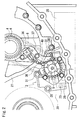
- FIG. 2 is a front view showing the oil pump and its vicinity according to the embodiment.
- a continuously variable transmission 1 to which power from an engine is input includes an input shaft 4 to which power is input from the engine via a torque converter 3, a forward/backward switching mechanism 9 that changes rotation directions of the power input to the input shaft 4, and a shift mechanism 10 that converts and transmits revolutions to wheels of a vehicle, not shown.
- a vane type oil pump 2 driven by torque from the input shaft 4 is disposed such that an oil pump rotary shaft 5 and the input shaft 4 are in parallel with each other.
- vane type oil pump 2 which is small and efficient and has high discharge pressure, is applied to the belt type continuously variable transmission that requires high hydraulic pressure.
- a drive sprocket 6 is provided between the torque converter 3 and the forward/backward switching mechanism 9 and directly connected to a pump impeller of the torque converter 3 as a rotary member.
- a chain 8 is looped over the drive sprocket 6 and a driven sprocket 7, which is provided on the oil pump rotary shaft 5 of the oil pump 2, to drive the oil pump 2.
- the input shaft 4 of the continuously variable transmission 1 can be reduced in axial length.
- An end of the oil pump 2 on a side opposite to the side on which the driven sprocket 7 is provided is connected to a transmission case 20 of the continuously variable transmission 1, so that the oil pump 2 is fixed.
- An oil strainer 11 is connected to a lower side of the oil pump 2 as viewed in FIG. 1.
- the oil pump 2 absorbs oil stored in the lower part of the continuously variable transmission 1 through the oil strainer 11.
- the oil is pressurized by a pressurizing mechanism 12 in the oil pump 2 and supplied to an oil channel provided on the transmission case 20 side.
- the oil pump 2 is fastened on the transmission case 20-by bolts 30, 31, and 32 that penetrate the oil pump 2 from the side on which the driven sprocket 7 is provided up to the transmission case 20 as shown in FIG. 2.
- a valve unit 35 is disposed in the lower part of the oil pump 2 at the back as viewed in FIG. 2, and hence the bolts cannot be inserted into the oil pump 2 from the front side as viewed in FIG. 2. Therefore, the bolts 30, 31, and 32 are concentrated in the upper part of the oil pump 2. Further, since an oil channel 28 connected to the oil strainer 11 is formed in the lower part of the oil pump 2, and hence through-holes for fixing the oil pump 2 cannot be formed in the lower part of the oil pump 2.
- threads are formed on a side that receives external force in such a direction as to pull the oil pump 2 away from the transmission case 20 due to tension of the chain 8 (the lower left-hand part of FIG. 3) and at a location set in the lower part of the oil pump 2 and as far as possible from an oil pump rotary shaft 5.
- the oil pump 2 is fixed to the transmission case 20 by inserting the bolt 33 from the reverse side of a wall of the transmission case 20 on which the oil pump 2 abuts.
- a sensor 36 that detects rotation of a drum within the forward/backward switching mechanism 9 is mounted on the partition member 27.
- Harnesses 38 are extended from the sensor 36 and connected to a transmission controller, not shown, provided in the vicinity of the valve unit 35.
- harnesses 38 are bound up halfway into a bundle having a circular cross-section surface.
- the partition member 27 and the oil pump 2 are connected to each other by a pump holding member 40.
- the pump holding member 40 is disposed in substantially parallel with the tensioning direction of the chain 8 as viewed from the axial direction of the oil pump rotary shaft 5, i.e. in FIG. 2.
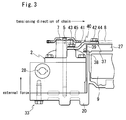
- FIG. 3 is a side view showing the way the oil pump 2 is supported.
- An end 44 of the pump holding member 40, which is fixed to the partition member 27, and an end 45 of the pump holding member 40, which is fixed to the oil pump 2, are offset from each other via a slope 41.
- the end 44 of the pump holding member 40 is fixed to the partition member 27 by a bolt 42 so that the end 44 can be prevented from interfering with the chain 8.
- a face of the transmission case 20, to which the oil pump 2 is connected, and a face of the partition member 27, to which the pump holding member 40 is connected, are offset for an axial direction of the oil pump rotary shaft 5.
- the amount of the offset is slightly lower than an axial height of the oil pump 2.
- the driven sprocket 7 of the oil pump 2 is disposed closer to the torque converter 3 than the partition member 27.
- the chain 8 is disposed such that a path plane which is defined by the path of the chain 8 and the face of the partition member 27 which is connected to the pump holding member 40 are in parallel with each other.
- the end 45 of the pump holding member 40 is offset downward from the end 44 as viewed in FIG. 3.
- the end 45 is located below the driven sprocket 7 while preventing from interfering with the chain 8 and the driven sprocket 7, and is fixed to the oil pump 2 by a bolt 43.
- the sensor 36 and a bracket 37 that supports the harnesses 38 extended from the sensor 36 are interposed between the end 44 and the partition member 27, and the bracket 37 as well as the pump holding member 40 is fastened with the bolt 42.
- the bracket 37 is bent in a direction away from the chain 8 to form a harness holding part 39.
- the harnesses 38 which connect the sensor 36 and the transmission controller to each other, cross the chain 8, and the harness holding part 39 holds the harnesses 38 on the reverse side of the pump holding member 40 (the side on which the pump holding member 40 abuts on the oil pump 2 and the partition member 37) so as to keep the harnesses 38 from interfering with the chain 8 and the driven sprocket 7.
- the location at which the end 45 of the pump holding member 40 is fixed to the oil pump 2 by the bolt 43 is set to be as far as possible from the oil pump rotary shaft 5 insofar as the bolt 43 can be inserted onto the oil pump 2.
- FIG. 4 shows the relationship in vibration frequency and noise when the oil pump 2 is driven between the case where the oil pump 2 is fixed by the pump holding member 40 and the bolt 33 and the case where the oil pump 2 is not fixed by the pump holding member 40 and the bolt 33.
- the pump holding member 40 is disposed in substantially parallel with the tensioning direction of the chain 8, for connecting the partition member 27 and the oil pump 2 to each other.
- vibration occurring in the tensioning direction of the chain 8 when the oil pump 2 is driven can be suppressed to reduce vibration noise.
- the harness holding part 39 holds the harnesses 38 on the reverse side of the pump holding member 40, the harnesses 38 extended from the sensor 36 can be prevented from interfering with the chain 8 and the driven sprocket 7, so that the harnesses 38 can be protected and prevented from being broken.
- the oil pump 2 is fixed by the bolt 33 on the side that receives external force in such a direction as to pull the oil pump 2 away from the transmission case 20 due to tension of the chain 8 acting when the oil pump 2 is driven, vibration occurring in the tensioning direction of the chain 8 when the oil pump 2 is driven and vibration occurring in the direction in which the oil pump 2 rotates about the oil pump rotary shaft 5 can be suppressed.
- the bolt 33 can be prevented from interfering with the oil channel 28 formed in the oil pump 2, making it easier to design the oil channel 28.
- the side of the oil pump 2 which receives external force in such a direction as to pull the oil pump 2 away from the transmission case 20 due to tension of the chain 8 is apart from the partition member 27, and hence if the side of the oil pump 2 which receives external force in such a direction as to pull the oil pump 2 away from the transmission case 20 is fixed by the pump holding member 4 fastened on the partition member 27, the pump holding member 40 must be long. Therefore, it is preferred that the oil pump 2 is fastened with the bolt 33 on the side that receives external force in such a direction as to pull the oil pump 2 away from the transmission case 20.
- the present invention is applied to a vane type oil pump that pulsates when discharging hydraulic pressure because of its high discharge pressure and high airtightness.
Landscapes
- Engineering & Computer Science (AREA)
- General Engineering & Computer Science (AREA)
- Mechanical Engineering (AREA)
- General Details Of Gearings (AREA)
- Devices For Conveying Motion By Means Of Endless Flexible Members (AREA)
Applications Claiming Priority (1)
| Application Number | Priority Date | Filing Date | Title |
|---|---|---|---|
| JP2004251447A JP2006070916A (ja) | 2004-08-31 | 2004-08-31 | 自動変速機におけるオイルポンプの支持構造 |
Publications (1)
| Publication Number | Publication Date |
|---|---|
| EP1630458A2 true EP1630458A2 (de) | 2006-03-01 |
Family
ID=35197964
Family Applications (1)
| Application Number | Title | Priority Date | Filing Date |
|---|---|---|---|
| EP05255249A Withdrawn EP1630458A2 (de) | 2004-08-31 | 2005-08-25 | Trägeranordnung für eine Ölpumpe eines automatischen Getriebes |
Country Status (3)
| Country | Link |
|---|---|
| US (1) | US20060054413A1 (de) |
| EP (1) | EP1630458A2 (de) |
| JP (1) | JP2006070916A (de) |
Cited By (1)
| Publication number | Priority date | Publication date | Assignee | Title |
|---|---|---|---|---|
| WO2010101266A1 (en) * | 2009-03-05 | 2010-09-10 | Toyota Jidosha Kabushiki Kaisha | Oil pump mounting structure |
Families Citing this family (3)
| Publication number | Priority date | Publication date | Assignee | Title |
|---|---|---|---|---|
| DE112009002360B4 (de) * | 2009-04-28 | 2015-11-26 | Toyota Jidosha Kabushiki Kaisha | Öldurchgangsstruktur einer Ölpumpe mit Kettenantrieb |
| KR101305185B1 (ko) * | 2011-08-08 | 2013-09-12 | 기아자동차주식회사 | 무단변속기의 오일펌프 지지부재 |
| US9290092B2 (en) * | 2013-06-11 | 2016-03-22 | GM Global Technology Operations LLC | Chain drive power take off for hydraulic pump |
Citations (1)
| Publication number | Priority date | Publication date | Assignee | Title |
|---|---|---|---|---|
| JP2003156127A (ja) | 2001-11-20 | 2003-05-30 | Jatco Ltd | オイルポンプの支持構造 |
Family Cites Families (2)
| Publication number | Priority date | Publication date | Assignee | Title |
|---|---|---|---|---|
| US2020435A (en) * | 1932-07-09 | 1935-11-12 | Best Foods Inc | Apparatus for regulating the mixing of ingredients |
| US4494943A (en) * | 1981-09-08 | 1985-01-22 | Nippondenso Co., Ltd. | Power transmission device for vehicles |
-
2004
- 2004-08-31 JP JP2004251447A patent/JP2006070916A/ja active Pending
-
2005
- 2005-08-25 EP EP05255249A patent/EP1630458A2/de not_active Withdrawn
- 2005-08-31 US US11/215,936 patent/US20060054413A1/en not_active Abandoned
Patent Citations (1)
| Publication number | Priority date | Publication date | Assignee | Title |
|---|---|---|---|---|
| JP2003156127A (ja) | 2001-11-20 | 2003-05-30 | Jatco Ltd | オイルポンプの支持構造 |
Cited By (5)
| Publication number | Priority date | Publication date | Assignee | Title |
|---|---|---|---|---|
| WO2010101266A1 (en) * | 2009-03-05 | 2010-09-10 | Toyota Jidosha Kabushiki Kaisha | Oil pump mounting structure |
| JP2010203575A (ja) * | 2009-03-05 | 2010-09-16 | Toyota Motor Corp | オイルポンプ取付構造 |
| CN102333974A (zh) * | 2009-03-05 | 2012-01-25 | 丰田自动车株式会社 | 油泵安装结构 |
| US8573953B2 (en) | 2009-03-05 | 2013-11-05 | Toyota Jidosha Kabushiki Kaisha | Oil pump mounting structure |
| CN102333974B (zh) * | 2009-03-05 | 2014-08-13 | 丰田自动车株式会社 | 油泵安装结构 |
Also Published As
| Publication number | Publication date |
|---|---|
| US20060054413A1 (en) | 2006-03-16 |
| JP2006070916A (ja) | 2006-03-16 |
Similar Documents
| Publication | Publication Date | Title |
|---|---|---|
| US7686137B2 (en) | Oil separating structure of automatic transmission | |
| US6572502B1 (en) | Chain tensioner device for use in a confined space | |
| EP0482781A1 (de) | Motor-Zusatzantriebsspanner | |
| US20060060424A1 (en) | Baffle plate | |
| EP1630458A2 (de) | Trägeranordnung für eine Ölpumpe eines automatischen Getriebes | |
| US6162125A (en) | Motor shaft to gear pump coupling device for fluid borne noise reduction | |
| JP4466025B2 (ja) | 自動変速機の電動ポンプ配設構造 | |
| US7017545B2 (en) | Balancer device of engine | |
| US20060054412A1 (en) | Oil pump driving structure of automatic transmission | |
| KR102646759B1 (ko) | 쉐어 볼트의 장착 구조 | |
| JP2011038588A (ja) | ベルト式クラッチ機構 | |
| JPH09257107A (ja) | 減速機付油圧モータ | |
| JP3751510B2 (ja) | 補助油圧ユニット付き自動変速機 | |
| JP2003156127A (ja) | オイルポンプの支持構造 | |
| KR100911395B1 (ko) | 조향장치용 유압펌프의 장착유닛 | |
| DE102006054517C5 (de) | Drehmomentübertragungseinrichtung | |
| JP3963366B2 (ja) | トランスミッションケース | |
| SE535389C2 (sv) | Elektrisk drivanordning | |
| JPH05307284A (ja) | 画像形成装置の駆動伝達機構 | |
| JP4248358B2 (ja) | モータとクラッチ・ブレーキユニットとの連結構造及びクラッチ・ブレーキユニット | |
| RU2381915C2 (ru) | Способ и система для получения определенного передаточного отношения, а также держатель опоры | |
| KR100380395B1 (ko) | 자동차용 리저버의 결합 보강구조 | |
| KR20060055585A (ko) | 댐퍼 풀리의 이탈방지장치 | |
| US20100210385A1 (en) | Tensioner assembly for a rotary drive | |
| KR100365206B1 (ko) | 자동차용 밸런스샤프트의 스프라켓기어 |
Legal Events
| Date | Code | Title | Description |
|---|---|---|---|
| PUAI | Public reference made under article 153(3) epc to a published international application that has entered the european phase |
Free format text: ORIGINAL CODE: 0009012 |
|
| AK | Designated contracting states |
Kind code of ref document: A2 Designated state(s): AT BE BG CH CY CZ DE DK EE ES FI FR GB GR HU IE IS IT LI LT LU LV MC NL PL PT RO SE SI SK TR |
|
| AX | Request for extension of the european patent |
Extension state: AL BA HR MK YU |
|
| STAA | Information on the status of an ep patent application or granted ep patent |
Free format text: STATUS: THE APPLICATION HAS BEEN WITHDRAWN |
|
| 18W | Application withdrawn |
Effective date: 20071228 |