EP1630391A1 - Vefahren und Vorrichtung zur Ermittlung eines Ausgabedrehmoments - Google Patents
Vefahren und Vorrichtung zur Ermittlung eines Ausgabedrehmoments Download PDFInfo
- Publication number
- EP1630391A1 EP1630391A1 EP05107233A EP05107233A EP1630391A1 EP 1630391 A1 EP1630391 A1 EP 1630391A1 EP 05107233 A EP05107233 A EP 05107233A EP 05107233 A EP05107233 A EP 05107233A EP 1630391 A1 EP1630391 A1 EP 1630391A1
- Authority
- EP
- European Patent Office
- Prior art keywords
- torque
- speed
- combustion engine
- internal combustion
- act
- Prior art date
- Legal status (The legal status is an assumption and is not a legal conclusion. Google has not performed a legal analysis and makes no representation as to the accuracy of the status listed.)
- Withdrawn
Links
Images


Classifications
-
- F—MECHANICAL ENGINEERING; LIGHTING; HEATING; WEAPONS; BLASTING
- F02—COMBUSTION ENGINES; HOT-GAS OR COMBUSTION-PRODUCT ENGINE PLANTS
- F02D—CONTROLLING COMBUSTION ENGINES
- F02D41/00—Electrical control of supply of combustible mixture or its constituents
- F02D41/02—Circuit arrangements for generating control signals
- F02D41/14—Introducing closed-loop corrections
- F02D41/16—Introducing closed-loop corrections for idling
-
- F—MECHANICAL ENGINEERING; LIGHTING; HEATING; WEAPONS; BLASTING
- F02—COMBUSTION ENGINES; HOT-GAS OR COMBUSTION-PRODUCT ENGINE PLANTS
- F02D—CONTROLLING COMBUSTION ENGINES
- F02D11/00—Arrangements for, or adaptations to, non-automatic engine control initiation means, e.g. operator initiated
- F02D11/06—Arrangements for, or adaptations to, non-automatic engine control initiation means, e.g. operator initiated characterised by non-mechanical control linkages, e.g. fluid control linkages or by control linkages with power drive or assistance
- F02D11/10—Arrangements for, or adaptations to, non-automatic engine control initiation means, e.g. operator initiated characterised by non-mechanical control linkages, e.g. fluid control linkages or by control linkages with power drive or assistance of the electric type
- F02D11/105—Arrangements for, or adaptations to, non-automatic engine control initiation means, e.g. operator initiated characterised by non-mechanical control linkages, e.g. fluid control linkages or by control linkages with power drive or assistance of the electric type characterised by the function converting demand to actuation, e.g. a map indicating relations between an accelerator pedal position and throttle valve opening or target engine torque
-
- F—MECHANICAL ENGINEERING; LIGHTING; HEATING; WEAPONS; BLASTING
- F02—COMBUSTION ENGINES; HOT-GAS OR COMBUSTION-PRODUCT ENGINE PLANTS
- F02D—CONTROLLING COMBUSTION ENGINES
- F02D41/00—Electrical control of supply of combustible mixture or its constituents
- F02D41/02—Circuit arrangements for generating control signals
- F02D41/0205—Circuit arrangements for generating control signals using an auxiliary engine speed control
-
- F—MECHANICAL ENGINEERING; LIGHTING; HEATING; WEAPONS; BLASTING
- F02—COMBUSTION ENGINES; HOT-GAS OR COMBUSTION-PRODUCT ENGINE PLANTS
- F02D—CONTROLLING COMBUSTION ENGINES
- F02D41/00—Electrical control of supply of combustible mixture or its constituents
- F02D41/02—Circuit arrangements for generating control signals
- F02D41/04—Introducing corrections for particular operating conditions
- F02D41/08—Introducing corrections for particular operating conditions for idling
-
- F—MECHANICAL ENGINEERING; LIGHTING; HEATING; WEAPONS; BLASTING
- F02—COMBUSTION ENGINES; HOT-GAS OR COMBUSTION-PRODUCT ENGINE PLANTS
- F02D—CONTROLLING COMBUSTION ENGINES
- F02D41/00—Electrical control of supply of combustible mixture or its constituents
- F02D41/02—Circuit arrangements for generating control signals
- F02D41/14—Introducing closed-loop corrections
- F02D41/1497—With detection of the mechanical response of the engine
-
- F—MECHANICAL ENGINEERING; LIGHTING; HEATING; WEAPONS; BLASTING
- F02—COMBUSTION ENGINES; HOT-GAS OR COMBUSTION-PRODUCT ENGINE PLANTS
- F02D—CONTROLLING COMBUSTION ENGINES
- F02D11/00—Arrangements for, or adaptations to, non-automatic engine control initiation means, e.g. operator initiated
- F02D11/06—Arrangements for, or adaptations to, non-automatic engine control initiation means, e.g. operator initiated characterised by non-mechanical control linkages, e.g. fluid control linkages or by control linkages with power drive or assistance
- F02D11/10—Arrangements for, or adaptations to, non-automatic engine control initiation means, e.g. operator initiated characterised by non-mechanical control linkages, e.g. fluid control linkages or by control linkages with power drive or assistance of the electric type
- F02D2011/101—Arrangements for, or adaptations to, non-automatic engine control initiation means, e.g. operator initiated characterised by non-mechanical control linkages, e.g. fluid control linkages or by control linkages with power drive or assistance of the electric type characterised by the means for actuating the throttles
- F02D2011/102—Arrangements for, or adaptations to, non-automatic engine control initiation means, e.g. operator initiated characterised by non-mechanical control linkages, e.g. fluid control linkages or by control linkages with power drive or assistance of the electric type characterised by the means for actuating the throttles at least one throttle being moved only by an electric actuator
-
- F—MECHANICAL ENGINEERING; LIGHTING; HEATING; WEAPONS; BLASTING
- F02—COMBUSTION ENGINES; HOT-GAS OR COMBUSTION-PRODUCT ENGINE PLANTS
- F02D—CONTROLLING COMBUSTION ENGINES
- F02D2200/00—Input parameters for engine control
- F02D2200/60—Input parameters for engine control said parameters being related to the driver demands or status
- F02D2200/602—Pedal position
-
- F—MECHANICAL ENGINEERING; LIGHTING; HEATING; WEAPONS; BLASTING
- F02—COMBUSTION ENGINES; HOT-GAS OR COMBUSTION-PRODUCT ENGINE PLANTS
- F02D—CONTROLLING COMBUSTION ENGINES
- F02D2250/00—Engine control related to specific problems or objectives
- F02D2250/18—Control of the engine output torque
-
- F—MECHANICAL ENGINEERING; LIGHTING; HEATING; WEAPONS; BLASTING
- F02—COMBUSTION ENGINES; HOT-GAS OR COMBUSTION-PRODUCT ENGINE PLANTS
- F02D—CONTROLLING COMBUSTION ENGINES
- F02D2250/00—Engine control related to specific problems or objectives
- F02D2250/18—Control of the engine output torque
- F02D2250/21—Control of the engine output torque during a transition between engine operation modes or states
Definitions
- the invention relates to a method and a device for determining an output torque according to the preambles of independent claims 1 and 9.
- E-accelerator encoders are used to determine a torque desired by the driver.
- the e-accelerator pedal In contrast to mechanical accelerator pedal, which are connected directly to the throttle valve, for example, in gasoline-powered internal combustion engines via Bowden cable, the e-accelerator pedal emit only an electrical signal that expresses the torque request of the driver.
- a torque structure receives the information from the e-accelerator, idle control, and various other consumers in the vehicle. From this information collected the required torque is calculated. This calculated torque is adjusted based on the various actuators of the internal combustion engine (eg electrically operated throttle valve).
- the e-gas is no direct connection between the driver and the internal combustion engine. As will be explained later, there is the possibility that at low speeds, in particular to the idle speed, a pedal play is present.
- a driver of an internal combustion engine moves the e-accelerator pedal over a certain range, without receiving a reaction of the internal combustion engine. This occurs especially when the internal combustion engine is idling.
- the idle control of the internal combustion engine requires a minimum torque of, for example, about 40 Nm, at the lowest possible Drehzal to keep the internal combustion engine in a stable operating condition. If the pedal transmitter of the E-gas is in its initial position - ie 0% -, the driver does not request torque of the internal combustion engine. If the driver moves the pedal encoder, the internal combustion engine does not react until the torque arranged by the driver is above the torque demanded by the idling control. To do this, the driver must deflect the pedal transmitter by approx. 6% from an initial position, ie between 0 and 6% of the pedal position, the driver does not feel any reaction from the internal combustion engine.
- the object of the invention is to provide a method and a device for determining an output torque such that the pedal transmitter or the accelerator pedal is free of play over the entire speed range of the internal combustion engine.
- the invention is characterized by a method and apparatus for determining an output torque to avoid a pedal play of an accelerator pedal associated with an internal combustion engine.
- a second torque is calculated for a, in particular the operating state of the internal combustion engine corresponding stable, idle speed. This can be done for example by an idle control.
- the current speed of the internal combustion engine can be measured for example by means of a speed sensor. From another speed and the current speed, the difference is formed, which forms the numerator of a quotient. In addition, from the further speed and from the Idle speed, the difference formed, which forms the denominator of the quotient. This quotient is multiplied by the second torque and gives a first torque. Such a calculation takes place, for example, in a correction unit.
- This inventive method or device according to the invention have the advantage over this entire idle range of the internal combustion engine to give the driver the impression that the internal combustion engine directly follows the gas pedal movements and reacts. By means of this invention, the engine hangs on the gas.
- FIGS. 1A to 1C have the same time axis and time division.
- Figure 1B the time course of a pedal position is located. At the time t 0 , the pedal is pressed linearly until the time t 3 . Between times t 3 and t 4 , the pedal is in full wrap. From the time t 4 , the accelerator pedal is linearly returned to its initial position until the time t 6 . This would correspond to a full throttle, drive between t 3 and t 4 in the full throttle range, and then between t 4 and t 6 take the foot off the accelerator pedal. When accelerating without correction results in the resulting torque shown in Figure 1a. The internal combustion engine is in the region a at idle.
- the ranges b and d indicate partial load ranges. And the area c indicates the full load range of the internal combustion engine.
- the torque output M res follows the pedal movement only within the time range t 1 and t 5 - As soon as the driver requires a lower torque than the idling torque M IS of the internal combustion engine, the driver feels no reaction from the internal combustion engine.
- FIG. 1C shows the time profile of a corrected torque according to the prior art, which corresponds to the chronological pedal curve depicted in FIG. 1B.
- the output torque M RIS is at idle M IS until time t 0 .
- the torque shown in FIG. 1C increases, however, the maximum torque M max already arrives at time t 2 , even though the accelerator pedal has not yet reached the full mark of 100%.
- the internal combustion engine supplies the maximum torque M max .
- the driver also feels no reaction. This shifts the pedal play in the upper speed range.
- the motor control can equate this full scale with the maximum torque M max , so that as in the areas t 4 and t 5 it can be seen that output torque follows the pedal movement.
- the torque desired by the driver is added to the idling torque M IS .
- the pedal play shifts depending on driving conditions in the higher or in the low no-load areas.
- FIG. 2 shows a block diagram of a device according to the invention.
- the device 1 comprises a mounted on the crankshaft of the internal combustion engine gear 2 with encoder teeth 3, a speed sensor 4, an idle control 5, a correction unit 6, an adding unit 7, a Pedalstellgeber 8 and a pedal adjusting unit 9 with a map KF.
- the rotational speed sensor 4 counts the encoder teeth 3 passing by it and thus mutes the current rotational speed N.
- the output of the rotational speed sensor 4 is connected to the input of the idling control 5.
- the idling control 5 turns on as soon as the current speed N is less than or equal to a turn-on speed N act .
- the output of the idle control is connected to the input of the correction unit 6.
- the correction unit 6 calculates the first torque or the correction torque M offset .
- the difference between the switch-on rotational speed N act and the current rotational speed N is formed, which forms the numerator of a quotient.
- the difference of the turn-on rotational speed N act is formed by the idle speed N soll , which represent the counter of the above-mentioned quotient.
- This quotient is multiplied by the second torque or idle torque.
- the correction torque Mo ffset is equal to 0, if the current speed is above the turn-on speed N act .
- the output of the correction unit 6 is connected to a first input of the adding unit 7.
- the output of the Pedalstellgebers 8 is connected to the input of the pedal adjusting unit 9. From the map KF the torque desired by the driver M PV is output. The output of the pedal adjusting unit 9 is connected to the second input of the adding unit 7. The two torques Mo ffset and M PV are added up in the adding unit 7 and produce the output torque M res .
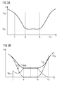
- FIGS. 3a and 3b show the change in speed as a function of time.
- FIG. 3b shows the change in the torque as a function of time, the time axes in FIGS. 3a and 3b being identical.
- a trough-like curve is shown, wherein the current speed of the internal combustion engine from the time t 7 falls below the turn-on speed N act .
- the current speed N remains below this switch-on speed N act until the time t 10 .
- the internal combustion engine reaches the idling speed N setpoint and remains at this idling speed N setpoint until time t 9 . From the time t 9 , the current speed increases, wherein from the time t 10, the current speed is greater than the turn-on speed N act .
- FIG. 3b three torque curves are shown.
- the dashed curve represents the idle torque M IS.
- the dash-dotted curve represents the desired by the driver torque M Primary.
- the solid curve is the output torque M res again.
- the solid line and the dot-dash line overlap before time t 7 and after time t 10 .
- the idle control 5 is active and outputs a corresponding idle torque M IS .
- the idling control 5 is inactive. From the time t 7 , the idle control 5 sits abruptly. In this case, the accelerator pedal is moved back from the time t 7 to the time t 8 to its starting position of 0%.
- the accelerator pedal is pressed again.
- the pedal movements are reinterpreted into corresponding torque requests of the driver M PV, as shown in phantom in FIG. 3b.
- the correction unit M offset is calculated by the correction unit 6 as described above.
- the output torque M offset to the driver's desired torque M PV equals to res as can be seen from the Figure 3b the correction torque M offset equal to the idle torque M is.
Landscapes
- Engineering & Computer Science (AREA)
- Chemical & Material Sciences (AREA)
- Combustion & Propulsion (AREA)
- Mechanical Engineering (AREA)
- General Engineering & Computer Science (AREA)
- Combined Controls Of Internal Combustion Engines (AREA)
- Electrical Control Of Air Or Fuel Supplied To Internal-Combustion Engine (AREA)
- Control Of Throttle Valves Provided In The Intake System Or In The Exhaust System (AREA)
Abstract
Description
- Die Erfindung betrifft ein Verfahren und eine Vorrichtung zur Ermittlung eines Ausgabedrehmoments nach den Oberbegriffen der unabhängigen Ansprüche 1 und 9.
- Zur Ermittlung eines vom Fahrer gewünschten Drehmoments werden E-Gaspedalgeber eingesetzt. Im Gegensatz zu mechanischen Gaspedal, die bei beispielsweise mit Benzin betriebenen Brennkraftmaschinen über Bowdenzug direkt an die Drosselklappe angeschlossen sind, geben die E-Gaspedalgeber lediglich ein elektrisches Signal ab, dass die Drehmomentanforderung des Fahrers zum Ausdruck bringt. Eine Drehmomentstruktur erhält die Informationen von dem E-Gaspedalgeber, von einer Leerlaufregelung und diversen anderen im Kraftfahrzeug befindlichen Verbrauchern. Aus diesen gesammelten Informationen wird das erforderliche Drehmoment berechnet. Dieses berechnete Drehmoment wird anhand der diversen Aktuatoren der Brennkraftmaschine (z. B. elektrisch betriebene Drosselklappe) eingestellt. Durch das E-Gas besteht keine direkte Verbindung zwischen Fahrer und der Brennkraftmaschine. Wie später näher erläutert wird, besteht die Möglichkeit, dass bei niedrigen Drehzahlen, insbesondere um die Leerlaufdrehzahl, ein Pedalspiel vorhanden ist. Darunter ist zu verstehen, dass ein Fahrer einer Brennkraftmaschine das E-Gaspedal über einen gewissen Bereich bewegt, ohne eine Reaktion der Brennkraftmaschine zu erhalten. Dies tritt vor allem dann auf, wenn sich die Brennkraftmaschine sich im Leerlauf befindet. Die Leerlaufregelung der Brennkraftmaschine verlangt ein minimales Drehmoment von beispielsweise ca. 40 Nm, bei möglichst niedrigster Drehzal die Brennkraftmaschine in einem stabilen Betriebszustand zu halten. Befindet sich der Pedalgeber des E-Gas in seiner Anfangsstellung - also 0% - , so fordert der Fahrer kein Drehmoment der Brennkraftmaschine an. Bewegt der Fahrer den Pedalgeber reagiert die Brennkraftmaschine solange nicht, bis der vom Fahrer angeordnete Drehmoment über dem von der Leerlaufregelung angeforderte Drehmoment liegt. Dazu muss der Fahrer den Pedalgeber um ca. 6% aus einer Anfangsposition auslenken, d. h. zwischen 0 und 6% der Pedalstellung spürt der Fahrer keine Reaktion der Brennkraftmaschine.
- Der Erfindung liegt die Aufgabe zugrunde ein Verfahren und eine Vorrichtung zu der Ermittlung eines Ausgabedrehmoments vorzustellen, dass im gesamten Drehzahlbereich der Brennkraftmaschine der Pedalgeber bzw. das Fahrpedal spielfrei ist.
- Die Erfindung wird durch die Merkmale des unabhängigen Anspruch 1 und durch die Merkmale des unabhängigen Anspruchs 9 gelöst.
- Die Erfindung zeichnet sich durch ein Verfahren bzw. Vorrichtung zur Ermittlung eines Ausgabe-Drehmoments aus, um ein Pedalspiel eines einer Brennkraftmaschine zugeordneten Fahrpedals zu vermeiden. Dabei wird ein zweites Drehmoment für eine, insbesondere dem Betriebszustand der Brennkraftmaschine entsprechende stabile, Leerlaufdrehzahl berechnet. Dies kann beispielsweise durch eine Leerlaufregelung durchgeführt werden. Die aktuelle Drehzahl der Brennkraftmaschine kann beispielsweise mittels eines Drehzahlsensors gemessen werden. Von einer weiteren Drehzahl und von der aktuellen Drehzahl wird die Differenz gebildet, die den Zähler eines Quotienten bildet. Außerdem wird von der weiteren Drehzahl und von der Leerlaufdrehzahl die Differenz gebildet, die den Nenner des Quotienten bildet. Dieser Quotient wird mit dem zweiten Drehmoment multipliziert und ergibt ein erstes Drehmoment. Eine solche Berechnung erfolgt beispielsweise in einer Korrektureinheit.
- Dieses erfindungsgemäße Verfahren bzw. erfindungsgemäße Vorrichtung haben den Vorteil über diesen gesamten Leerlaufbereich der Brennkraftmaschine dem Fahrer den Eindruck zu vermitteln, dass die Brennkraftmaschine den Gaspedalbewegungen unmittelbar folgt und reagiert. Mittels dieser Erfindung hängt der Motor am Gas.
- Eine vorteilhafte Ausgestaltung der Erfindung ist es die Berechnung des zweiten Drehmoments erst dann auszuführen, wenn die aktuelle Drehzahl unterhalb der weiteren Drehzahl bzw. Einschaltdrehzahl liegt. Oberhalb dieser Einschaltdrehzahl kann das erste Drehmoment gleich 0 gesetzt werden. Dies hat den Vorteil, dass die Korrekturberechnungen oberhalb der Einschaltdrehzahl abgeschlossen sind. Damit wird vermieden, dass die Motorsteuerung in höheren Drehzahlbereichen mit zusätzlichen Berechnungsfunktionen belastet wird. Weitere vorteilhafte Ausgestaltungen der Erfindung sind in den übrigen abhängigen Ansprüchen angegeben. Die Erfindung wird nachfolgend unter Bezugnahme auf die schematische Zeichnung beispielhaft erläutert. Dabei zeigt:
- Figur 1B
- einen zeitlichen Verlauf eines Pedalgebers;
- Figuren 1A, 1C
- die entsprechenden Drehmomentverläufe mit und ohne Korrektur nach dem Stand der Technik;
- Figur 3A
- einen zeitlichen Verlauf der Drehzahl; und
- Figur 3B
- der zeitliche Verlauf des Drehmoments gemäß der Erfindung.
- Figuren 1A bis 1C weisen dieselbe Zeitachse und Zeiteinteilung auf. In Figur 1B ist der zeitliche Verlauf einer Pedalstellung eingezeichnet. Zum Zeitpunkt t0 wird das Pedal bis zum Zeitpunkt t3 linear durchgedrückt. Zwischen Zeitpunkten t3 und t4 befindet sich das Pedal im Volleinschlag. Von dem Zeitpunkt t4 wird das Fahrpedal linear in seine Ausgangsstellung bis zum Zeitpunkt t6 zurückgefahren. Dies entspräche einem Vollgasgeben, zwischen t3 und t4 im Vollgasbereich fahren, und anschließend zwischen t4 und t6 den Fuß vom Gaspedal nehmen. Beim Gasgeben ohne Korrektur ergibt sich das daraus resultierende in Figur 1a abgebildete Drehmoment. Die Brennkraftmaschine befindet sich im Bereich a im Leerlauf. Obwohl das Gaspedal zum Zeitpunkt t0 bereits betätigt wird, reagiert die Brennkraftmaschine erst zum Zeitpunkt t1 auf die Bewegung des Pedalgebers. Zwischen den Zeitpunkten t0 und t1 ergibt sich somit ein Pedalspiel von PVreac. 6% vom Vollausschlag sind als Pedalspiel üblich. In Figur 1b sind sogar 24% Pedalspiel eingezeichnet. Das maximale von der Brennkraftmaschine zur Verfügung stehende Drehmoment Mmax wird zum Zeitpunkt t3 erreicht. Bis zum Zeitpunkt t4 wird das maximale Drehmoment Mmax von der Brennkraftmaschine ausgegeben. Danach fällt das Drehmoment linear ab bis zum Leerlaufdrehmoment MIS zum Zeitpunkt t5. Danach liefert die Brennkraftmaschine das Leerlaufdrehmoment MIS. Die Bereiche a und e geben Leerlaufbereiche an. Die Bereich b und d geben Teillastbereiche an. Und der Bereich c gibt den Volllastbereich der Brennkraftmaschine an. Wie zu erkennen ist, folgt die Drehmomentausgabe Mres der Pedalbewegung nur innerhalb des Zeitbereichs t1 und t5- Sobald der Fahrer ein geringeres Drehmoment als das Leerlaufdrehmoment MIS von der Brennkraftmaschine verlangt, spürt der Fahrer von der Brennkraftmaschine keine Reaktion.
- In Figur 1C ist der zeitliche Verlauf eines korrigierten Drehmoments nach dem Stand der Technik abgebildet, das der in Figur 1B abgebildete zeitliche Pedalverlauf entspricht. Das Ausgabedrehmoment MRIS befindet sich bis zum Zeitpunkt t0 im Leerlauf MIS. Sobald zum Zeitpunkt t0 das Pedal verschoben wird erhöht sich das in Figur 1C abgebildete Drehmoment jedoch erreicht das maximale Drehmoment Mmax bereits zum Zeitpunkt t2, obwohl das Gaspedal den Vollaufschlag von 100% noch nicht erreicht hat. Zwischen den Zeitpunkten t2 und t4 liefert die Brennkraftmaschine das maximale Drehmoment Mmax. Zwischen den Zeitpunkten t2 und t3 spürt der Fahrer ebenfalls keine Reaktion. Damit verlagert sich das Pedalspiel in den oberen Drehzahlbereich. Nach erreichen des Vollausschlags kann die Motorsteuerung diesen Vollausschlag dem maximalen Drehmoment Mmax gleichsetzen, so dass wie in den Bereichen t4 und t5 zu sehen ist, dass Ausgabedrehmoment der Pedalbewegung folgt. Sobald das Gaspedal seine Ausgangsstellung erreicht wird wie in t0 das vom Fahrer gewünschte Drehmoment auf das Leerlaufdrehmoment MIS aufaddiert. So verschiebt sich das Pedalspiel je nach Fahrbedingung in den höheren bzw. in den niedrigen Leerlaufbereichen.
- In Figur 2 ist ein Blockschaltbild einer erfindungsgemäßen Vorrichtung abgebildet. Die Vorrichtung 1 umfasst ein auf der Kurbelwelle der Brennkraftmaschine montiertes Zahnrad 2 mit Geberzähnen 3, einem Drehzahlsensor 4, eine Leerlaufregelung 5, eine Korrektureinheit 6, eine Addiereinheit 7, ein Pedalstellgeber 8 und eine Pedalstelleinheit 9 mit einem Kennfeld KF. Der Drehzahlsensor 4 zählt die an ihm vorbeilaufenden Geberzähnen 3 und mist somit die aktuelle Drehzahl N. Der Ausgang des Drehzahlsensors 4 ist an dem Eingang der Leerlaufregelung 5 angeschlossen. Die Leerlaufregelung 5 schaltet sich ein, sobald die aktuelle Drehzahl N kleiner gleich einer Einschaltdrehzahl Nact ist. Als Sollwert erhält die Leerlaufregelung 5 die Leerlaufdrehzahl Nsoll. Mit diesen Informationen berechnet die Leerlaufregelung 5 das erforderliche Leerlaufdrehmoment MIS. Der Ausgang der Leerlaufregelung ist an den Eingang der Korrektureinheit 6 angeschlossen. Die Korrektureinheit 6 berechnet das erste Drehmoment bzw. das Korrekturdrehmoment Moffset.
- Bei der Berechnung wird zuerst die Differenz aus der Einschaltdrehzahl Nact und der aktuellen Drehzahl N gebildet, die den Zähler eines Quotienten bildet. Anschließend wird die Differenz von der Einschaltdrehzahl Nact von der Leerlaufdrehzahl Nsoll gebildet, die den Zähler des oben erwähnten Quotienten darstellen. Dieser Quotient wird mit dem zweiten Drehmoment bzw. Leerlaufdrehmoment multipliziert. Dabei ist das Korrekturdrehmoment Moffset gleich 0, wenn die aktuelle Drehzahl über der Einschaltdrehzahl Nact ist. Der Ausgang der Korrektureinheit 6 ist an einem ersten Eingang der Addiereinheit 7 angeschlossen.
- Der Ausgang des Pedalstellgebers 8 ist an den Eingang der Pedalstelleinheit 9 angeschlossen. Aus dem Kennfeld KF wird das vom Fahrer gewünschte Drehmoment MPV ausgegeben. Der Ausgang der Pedalstelleinheit 9 ist an den zweiten Eingang der Addiereinheit 7 angeschlossen. Die beiden Drehmomente Moffset und MPV werden in der Addiereinheit 7 aufaddiert und ergeben das Ausgabedrehmoment Mres.
- Anhand der Figuren 3a und b wird das erfindungsgemäße Verfahren erläutert. Dabei zeigt Figur 3a die Änderung der Drehzahl in Abhängigkeit von der Zeit. Figur 3b zeigt die Änderung des Drehmoments in Abhängigkeit der Zeit, wobei die Zeitachsen in den Figuren 3a und b identisch sind. In Figur 3a ist eine Wannenartige Kurve gezeigt, wobei die aktuelle Drehzahl der Brennkraftmaschine ab dem Zeitpunkt t7 die Einschaltdrehzahl Nact unterschreitet. Die aktuelle Drehzahl N bleibt unterhalb dieser Einschaltdrehzahl Nact bis zum Zeitpunkt t10. Zum Zeitpunkt t8 erreicht die Brennkraftmaschine die Leerlaufdrehzahl Nsoll und bleibt auf dieser Leerlaufdrehzahl Nsoll bis zum Zeitpunkt t9. Ab dem Zeitpunkt t9 erhöht sich die aktuelle Drehzahl, wobei ab dem Zeitpunkt t10 die aktuelle Drehzahl größer als die Einschaltdrehzahl Nact ist.
- In Figur 3b sind drei Drehmomentkurven eingezeichnet. Die gestrichelte Kurve stellt das Leerlaufdrehmoment MIS dar. Die strichpunktierte Kurve stellt das vom Fahrer gewünschten Drehmoments MPV dar. Die durchgezogene Kurve gibt das Ausgabedrehmoment Mres wieder. Wie aus der Figur 3b zu erkennen ist überlappen sich die durchgezogene und die strichpunktierte Linie vor dem Zeitpunkt t7 und nach dem Zeitpunkt t10. Zwischen den Zeitpunkten t7 und t10 ist die Leerlaufregelung 5 aktiv und gibt ein entsprechendes Leerlaufdrehmoment MIS aus. Außerhalb dieses Zeitbereichs t7 und t10 ist die Leerlaufregelung 5 inaktiv. Ab dem Zeitpunkt t7 sitzt die Leerlaufregelung 5 sprunghaft ein. Dabei wird das Fahrpedal vom Zeitpunkt t7 bis zum Zeitpunkt t8 auf seine Ausgangsposition von 0% zurückgefahren. Dort verbleibt es bis zum Zeitpunkt t9. Ab dann wird das Fahrpedal wieder betätigt. Anhand des in der Pedalstelleinheit 9 abgespeicherten Kennfeldes KF werden die Pedalbewegungen in entsprechende Drehmomentswünsche des Fahrers MPV wie in der Figur 3b strichpunktiert dargestellt umgedeutet. Zwischen den Zeitpunkten t7 und t10 wird von der Korrektureinheit 6 wie oben beschrieben das Korrekturdrehmoment Moffset berechnet. Durch die Addition des Korrekturdrehmoments Moffset auf das vom Fahrer gewünschten Drehmoments MPV ergibt sich das Ausgabedrehmoment Mres wie aus der Figur 3b zu erkennen ist ist das Korrekturdrehmoment Moffset gleich dem Leerlaufdrehmoment Mis.
- Mit diesem erfindungsgemäßen Verfahren und dieser erfindungsgemäßen Vorrichtung ist sichergestellt, dass am Pedalstellgeber für den Fahrer kein Spiel erkennbar ist.
Claims (10)
- Verfahren zur Ermittlung eines Ausgabedrehmoments (Mres) um ein Pedalspiel einer Brennkraftmaschine zugeordneten Fahrpedals zu vermeiden, wobei ein zweites Drehmoment (MIS) für eine, insbesondere dem Betriebszustand der Brennkraftmaschine entsprechend stabile, Leerlaufdrehzahl (Nsoll) berechnet wird und die aktuelle Drehzahl (N) der Brennkraftmaschine gemessen wird, dadurch gekennzeichnet, dass von einer weiteren Drehzahl (Nact) und von der Leerlaufdrehzahl (Nsoll) die Differenz gebildet wird, die den Nenner des Quotienten bildet, wobei die Multiplikation des Quotienten mit dem zweiten Drehmoment (MIS) ein erstes Drehmoment (Moffset) ergibt.
- Verfahren nach Anspruch 1, dadurch gekennzeichnet, dass die weitere Drehzahl (Nact) einer Einschaltdrehzahl (Nact) entspricht, wobei das zweite Drehmoment (MIS) erst berechnet wird, wenn die aktuelle Drehzahl (N) kleiner gleich der Einschaltdrehzahl (Nact) ist.
- Verfahren nach Anspruch 2, dadurch gekennzeichnet, dass die Einschaltdrehzahl (Nact) zwischen 500 Umin-1 und 1500 Umin-1 liegt.
- Verfahren nach mindestens einem der vorherigen Ansprüche, dadurch gekennzeichnet, dass das zweite Drehmoment (MIS) durch eine Leerlaufregelung der Brennkraftmaschine berechnet wird.
- Verfahren nach mindestens einem der vorherigen Ansprüche, dadurch gekennzeichnet, dass das erste Drehmoment (Moffset) gleich Null ist, wenn die aktuelle Drehzahl (N) größer ist als die Einschaltdrehzahl (Nact) ist.
- Verfahren nach mindestens einem der Ansprüche 1 - 4, dadurch gekennzeichnet, dass das erste Drehmoment (Moffset) bei maximaler Pedalstellung (PVmax) gleich null ist.
- Verfahren nach mindestens einem der vorherigen Ansprüche, dadurch gekennzeichnet, dass einer Pedalstellung (PV) zugeordnetes Drehmoment (MPV) mit dem ersten Drehmoment (Moffset) addiert wird.
- Verfahren nach mindestens einem der vorherigen Ansprüche, dadurch gekennzeichnet, dass das zweite Drehmoment (MIS) von mindestens einem an der Brennkraftmaschine angeschlossenen Verbraucher abhängt.
- Vorrichtung zur Ermittlung eines Ausgabe-Drehmoments (Mres) mit einem Drehzahlsensor zur Messung der aktuellen Drehzahl (N) einer Brennkraftmaschine, mit einer Leerlaufregelung (5) zur Berechnung eines zweiten Drehmoments (MIS), an die der Drehzahlsensor (4) angeschlossen ist, mit einer Korrektureinheit (6)zur Berechnung eines ersten Drehmoments (Moffset), an die der Ausgang der Leerlaufregelung (5) angeschlossen ist, dadurch gekennzeichnet, dass die Korrektureinheit (6) eine erste Differenz von einer weiteren Drehzahl (Nact) und von der aktuellen Drehzahl und eine zweite Differenz von der weiteren Drehzahl (Nact) und von einer vom zweiten Drehmoment (MIS) abhängigen Leerlaufdrehzahl (Nsoll) bildet, wobei die Korrektureinheit (6) einen Quotienten aus der ersten und zweiten Differenz berechnet, wobei am Ausgang der Korrektureinheit (6) die Multiplikation des Quotienten mit dem zweiten Drehmoment (MIS) anliegt.
- Vorrichtung nach Anspruch 9, dadurch gekennzeichnet, dass die Vorrichtung einen Pedalstellgeber (8), eine Pedalstelleinheit (9) mit einem Kennfeld (KF) und eine Addiereinheit (7) aufweist, wobei der Pedalstellgeber an dem Eingang der Pedalstelleinheit (9) angeschlossen ist und die Ausgänge der Pedalstelleinheit (9) und der Korrektureinheit (6) an die entsprechenden Eingänge der Addiereinheit (7) angeschlossen sind.
Applications Claiming Priority (1)
| Application Number | Priority Date | Filing Date | Title |
|---|---|---|---|
| DE102004041660A DE102004041660B3 (de) | 2004-08-27 | 2004-08-27 | Verfahren und Vorrichtung zur Ermittlung eines Ausgabedrehmoments |
Publications (1)
| Publication Number | Publication Date |
|---|---|
| EP1630391A1 true EP1630391A1 (de) | 2006-03-01 |
Family
ID=35160129
Family Applications (1)
| Application Number | Title | Priority Date | Filing Date |
|---|---|---|---|
| EP05107233A Withdrawn EP1630391A1 (de) | 2004-08-27 | 2005-08-05 | Vefahren und Vorrichtung zur Ermittlung eines Ausgabedrehmoments |
Country Status (3)
| Country | Link |
|---|---|
| US (1) | US7204229B2 (de) |
| EP (1) | EP1630391A1 (de) |
| DE (1) | DE102004041660B3 (de) |
Cited By (1)
| Publication number | Priority date | Publication date | Assignee | Title |
|---|---|---|---|---|
| FR2905417A1 (fr) * | 2006-08-29 | 2008-03-07 | Bosch Gmbh Robert | Procede de gestion d'un moteur a combustion interne |
Families Citing this family (3)
| Publication number | Priority date | Publication date | Assignee | Title |
|---|---|---|---|---|
| JP4345747B2 (ja) * | 2006-01-30 | 2009-10-14 | トヨタ自動車株式会社 | 内燃機関の制御装置 |
| WO2008019645A1 (de) * | 2006-08-16 | 2008-02-21 | Adc Automotive Distance Control System Gmbh | Verfahren zur abstandsregelung |
| DE102006061561A1 (de) * | 2006-12-27 | 2008-07-03 | Robert Bosch Gmbh | Verfahren zum Betreiben einer Brennkraftmaschine |
Citations (5)
| Publication number | Priority date | Publication date | Assignee | Title |
|---|---|---|---|---|
| DE4100380A1 (de) * | 1991-01-09 | 1992-07-16 | Vdo Schindling | Verfahren zum betreiben einer drosselklappengeregelten brennkraftmaschine im leerlaufregelbereich |
| GB2312970A (en) * | 1996-05-11 | 1997-11-12 | Ford Motor Co | Diesel engine control |
| EP1052390A2 (de) * | 1999-05-10 | 2000-11-15 | Ford Global Technologies, Inc. | Vorrichtung und Verfahren für das Verbessern von Übergängen zwischen Motorbetriebsarten |
| DE10047602A1 (de) * | 2000-09-26 | 2002-04-18 | Siemens Ag | Verfahren zum Betreiben einer Brennkraftmaschine |
| EP1277940A2 (de) * | 2001-07-19 | 2003-01-22 | Robert Bosch Gmbh | Verfahren und Vorrichtung zum Betreiben eines Antriebmotors |
Family Cites Families (7)
| Publication number | Priority date | Publication date | Assignee | Title |
|---|---|---|---|---|
| IL49201A (en) * | 1976-03-12 | 1980-02-29 | Scientific Res Foundation | Vehicle drive system including a flywheel and selectable coupling means |
| IT1241215B (it) * | 1990-05-07 | 1993-12-29 | Fiat Auto Spa | Procedimento ed apparato per il controllo della velocita' di rotazione al minimo di un motore a combustione interna. |
| DE19501299B4 (de) * | 1995-01-18 | 2006-04-13 | Robert Bosch Gmbh | Verfahren und Vorrichtung zur Steuerung einer Brennkraftmaschine eines Fahrzeugs |
| JP3710073B2 (ja) | 1997-03-31 | 2005-10-26 | 三菱自動車工業株式会社 | 吸気絞り弁制御装置 |
| ES2166589T3 (es) * | 1998-04-24 | 2002-04-16 | Doornes Transmissie Bv | Conjunto de accionamiento para vehiculo. |
| DE10000918A1 (de) * | 2000-01-12 | 2001-07-19 | Volkswagen Ag | Verfahren und Vorrichtung zur Steuerung einer Brennkraftmaschine |
| US6909959B2 (en) * | 2003-03-07 | 2005-06-21 | Stephen James Hallowell | Torque distribution systems and methods for wheeled vehicles |
-
2004
- 2004-08-27 DE DE102004041660A patent/DE102004041660B3/de not_active Expired - Fee Related
-
2005
- 2005-08-05 EP EP05107233A patent/EP1630391A1/de not_active Withdrawn
- 2005-08-25 US US11/211,419 patent/US7204229B2/en not_active Expired - Fee Related
Patent Citations (5)
| Publication number | Priority date | Publication date | Assignee | Title |
|---|---|---|---|---|
| DE4100380A1 (de) * | 1991-01-09 | 1992-07-16 | Vdo Schindling | Verfahren zum betreiben einer drosselklappengeregelten brennkraftmaschine im leerlaufregelbereich |
| GB2312970A (en) * | 1996-05-11 | 1997-11-12 | Ford Motor Co | Diesel engine control |
| EP1052390A2 (de) * | 1999-05-10 | 2000-11-15 | Ford Global Technologies, Inc. | Vorrichtung und Verfahren für das Verbessern von Übergängen zwischen Motorbetriebsarten |
| DE10047602A1 (de) * | 2000-09-26 | 2002-04-18 | Siemens Ag | Verfahren zum Betreiben einer Brennkraftmaschine |
| EP1277940A2 (de) * | 2001-07-19 | 2003-01-22 | Robert Bosch Gmbh | Verfahren und Vorrichtung zum Betreiben eines Antriebmotors |
Cited By (1)
| Publication number | Priority date | Publication date | Assignee | Title |
|---|---|---|---|---|
| FR2905417A1 (fr) * | 2006-08-29 | 2008-03-07 | Bosch Gmbh Robert | Procede de gestion d'un moteur a combustion interne |
Also Published As
| Publication number | Publication date |
|---|---|
| US7204229B2 (en) | 2007-04-17 |
| DE102004041660B3 (de) | 2006-05-04 |
| US20060048749A1 (en) | 2006-03-09 |
Similar Documents
| Publication | Publication Date | Title |
|---|---|---|
| DE3504181C2 (de) | Vorrichtung zur Steuerung der Ansaugluftmenge von Brennkraftmaschinen in Kraftfahrzeugen | |
| DE10020463B4 (de) | Fahrzeug- und Motorsteuersystem | |
| DE19808167C1 (de) | Verfahren zur Korrektur eines rechnerisch ermittelten Drehmoments im Antriebsstrang eines Kraftfahrzeugs | |
| DE4138822A1 (de) | Geraet zur erfassung des fahrwiderstandes eines fahrzeugs | |
| DE10234434B4 (de) | Verfahren zum Steuern einer Drosselklappe eines Motors eines Kraftfahrzeugs | |
| EP1250525B1 (de) | Verfahren und vorrichtung zur steuerung einer brennkraftmaschine | |
| DE19703685C2 (de) | Verfahren und Einrichtung zum Steuern einer Brennkraftmaschine | |
| EP0807208A1 (de) | Verfahren und vorrichtung zur steuerung einer brennkraftmaschine | |
| EP1924475B1 (de) | Verfahren zur begrenzung von sollmomenten bei der motorsteuerung | |
| DE19813717C2 (de) | Drosselklappensteuerungsvorrichtung und -verfahren | |
| DE19523898A1 (de) | Verfahren und Vorrichtung zur Steuerung der Antriebsiebseinheit eines Kraftfahrzeugs | |
| EP1005609B1 (de) | Verfahren zur steuerung der abgasrückführung bei einer brennkraftmaschine | |
| DE102008001636A1 (de) | Steuergerät für eine Quelle einer Drehantriebskraft | |
| EP1526984B1 (de) | Verfahren und vorrichtung zur signalisierung mehrerer für den betrieb eines kraftfahrzeugs relevanter informationen | |
| DE10148343B4 (de) | Verfahren und Vorrichtung zur Steuerung einer Antriebseinheit | |
| DE4313746C2 (de) | Verfahren und Vorrichtung zur Steuerung der Leistung einer Antriebseinheit eines Fahrzeugs | |
| EP1432899B1 (de) | Verfahren und vorrichtung zum betreiben eines antriebsmotors eines fahrzeugs | |
| DE102004041660B3 (de) | Verfahren und Vorrichtung zur Ermittlung eines Ausgabedrehmoments | |
| EP2173990B1 (de) | Verfahren und vorrichtung zum betreiben einer antriebseinheit | |
| DE4426972B4 (de) | Verfahren und Vorrichtung zur Steuerung einer Brennkraftmaschine | |
| DE10305092B4 (de) | Verfahren zur automatischen Anpassung eines Drehmomentenmodells sowie Schaltungsanordnung | |
| EP1286033A2 (de) | Verfahren zum Betreiben einer Brennkraftmaschine sowie Anfahrregler für ein Kraftfahrzeug | |
| DE60224018T2 (de) | Pedalkalibrierung für Kraftfahrzeuge | |
| DE10150422A1 (de) | Verfahren und Vorrichtung zur Ermittlung eines Fahrerwunsches | |
| DE10044412A1 (de) | Vorrichtung und Verfahren zur Adaption von Kennfeldwerten in Steuergeräten |
Legal Events
| Date | Code | Title | Description |
|---|---|---|---|
| PUAI | Public reference made under article 153(3) epc to a published international application that has entered the european phase |
Free format text: ORIGINAL CODE: 0009012 |
|
| AK | Designated contracting states |
Kind code of ref document: A1 Designated state(s): AT BE BG CH CY CZ DE DK EE ES FI FR GB GR HU IE IS IT LI LT LU LV MC NL PL PT RO SE SI SK TR |
|
| AX | Request for extension of the european patent |
Extension state: AL BA HR MK YU |
|
| 17P | Request for examination filed |
Effective date: 20060901 |
|
| AKX | Designation fees paid |
Designated state(s): DE FR |
|
| 17Q | First examination report despatched |
Effective date: 20061013 |
|
| RAP1 | Party data changed (applicant data changed or rights of an application transferred) |
Owner name: CONTINENTAL AUTOMOTIVE GMBH |
|
| STAA | Information on the status of an ep patent application or granted ep patent |
Free format text: STATUS: THE APPLICATION IS DEEMED TO BE WITHDRAWN |
|
| 18D | Application deemed to be withdrawn |
Effective date: 20100302 |