EP1629997A1 - Rim for a bicycle spoked wheel, wheel and manufacturing method - Google Patents
Rim for a bicycle spoked wheel, wheel and manufacturing method Download PDFInfo
- Publication number
- EP1629997A1 EP1629997A1 EP04425653A EP04425653A EP1629997A1 EP 1629997 A1 EP1629997 A1 EP 1629997A1 EP 04425653 A EP04425653 A EP 04425653A EP 04425653 A EP04425653 A EP 04425653A EP 1629997 A1 EP1629997 A1 EP 1629997A1
- Authority
- EP
- European Patent Office
- Prior art keywords
- infraspoke
- zones
- rim
- sub
- zone
- Prior art date
- Legal status (The legal status is an assumption and is not a legal conclusion. Google has not performed a legal analysis and makes no representation as to the accuracy of the status listed.)
- Granted
Links
- 238000004519 manufacturing process Methods 0.000 title claims description 7
- 230000009467 reduction Effects 0.000 claims description 62
- 239000000463 material Substances 0.000 claims description 19
- 238000000034 method Methods 0.000 claims description 11
- 239000002131 composite material Substances 0.000 claims description 5
- 230000007704 transition Effects 0.000 claims description 5
- 239000011159 matrix material Substances 0.000 claims description 4
- 238000003486 chemical etching Methods 0.000 claims description 3
- 238000009826 distribution Methods 0.000 claims description 3
- 238000009760 electrical discharge machining Methods 0.000 claims description 3
- 238000003801 milling Methods 0.000 claims description 3
- 239000002184 metal Substances 0.000 description 9
- 229910052751 metal Inorganic materials 0.000 description 9
- 229910001369 Brass Inorganic materials 0.000 description 7
- 239000010951 brass Substances 0.000 description 7
- 230000000694 effects Effects 0.000 description 7
- 238000003466 welding Methods 0.000 description 7
- 229910052782 aluminium Inorganic materials 0.000 description 4
- XAGFODPZIPBFFR-UHFFFAOYSA-N aluminium Chemical compound [Al] XAGFODPZIPBFFR-UHFFFAOYSA-N 0.000 description 4
- 229920000049 Carbon (fiber) Polymers 0.000 description 3
- 239000004917 carbon fiber Substances 0.000 description 3
- 238000003780 insertion Methods 0.000 description 3
- 230000037431 insertion Effects 0.000 description 3
- VNWKTOKETHGBQD-UHFFFAOYSA-N methane Chemical compound C VNWKTOKETHGBQD-UHFFFAOYSA-N 0.000 description 3
- 210000002445 nipple Anatomy 0.000 description 3
- 238000004026 adhesive bonding Methods 0.000 description 2
- 238000003490 calendering Methods 0.000 description 2
- 210000000080 chela (arthropods) Anatomy 0.000 description 2
- 238000000465 moulding Methods 0.000 description 2
- 239000007787 solid Substances 0.000 description 2
- 239000000126 substance Substances 0.000 description 2
- 229910000838 Al alloy Inorganic materials 0.000 description 1
- 229910000851 Alloy steel Inorganic materials 0.000 description 1
- 239000007795 chemical reaction product Substances 0.000 description 1
- 238000001125 extrusion Methods 0.000 description 1
- 239000002657 fibrous material Substances 0.000 description 1
- 230000007935 neutral effect Effects 0.000 description 1
- 239000010959 steel Substances 0.000 description 1
- 238000009827 uniform distribution Methods 0.000 description 1
- 230000003313 weakening effect Effects 0.000 description 1
Images








Classifications
-
- B—PERFORMING OPERATIONS; TRANSPORTING
- B60—VEHICLES IN GENERAL
- B60B—VEHICLE WHEELS; CASTORS; AXLES FOR WHEELS OR CASTORS; INCREASING WHEEL ADHESION
- B60B21/00—Rims
Definitions
- the present invention concerns, in general, the field of bicycle spoked wheels, and in particular a rim for a bicycle spoked wheel, a spoked wheel comprising such a rim and a method for manufacturing a rim for bicycle spoked wheel.
- a bicycle spoked wheel conventionally comprises a rim, a hub and a set of spoke connections between the rim and the hub.
- spoke having a widened head at a first end, and an outer threading at a second end opposite the first end.
- the widened head of the spoke is received in a suitably shaped seat, usually made at the hub or at a flange thereof.
- a bend is typically provided close to the first end of the spoke. The bend of the spoke at the first end can, however, be left out, for example in the case of use of a hub as described in US 2002/0033635 .
- the threading at the second end of the spoke is threadedly coupled in a threaded hole usually made at the rim or, preferably, in a removable connection element of the nipple type or nut type, which abuts at seating holes in the rim, possibly through the interposition of a plate, as illustrated for example in EP 0 936 085 .
- Spokes with different attachment means to the rim and to the hub are also known, for example in which the head of the spoke is intended to couple with the rim, and the threading of the spoke is intended to couple with the hub, and the present invention is not limited to any particular type of spoke connection.
- spoke connection it is meant to indicate the set of a spoke and possible removable connection elements, such as the aforementioned nipple and interposition plate.
- the hub is an element with rotational symmetry with respect to the axis of the bicycle wheel, and the spoke connections are always so distributed along the circumference of the wheel that the center of mass of them as a whole is at the axis of the wheel. More specifically, the spoke connections can be distributed equally spaced apart, or else groups of two or more spoke connections can be distributed equally spaced apart along the rim.
- spoke connections Due to the different angle of the spoke connections with respect to the median plane of the wheel (camber) between one side and the other of the hub and/or due to a tangential attachment of the spokes to a side of the hub and/or for other reasons in particularly complex spoke patterns, there can be spoke connections of different mass, but still forming regular, with respect to the rotation axis, sub-sets of identical spoke connections. Also in such cases, the center of mass of the set of spoke connections is therefore at the rotation axis of the wheel, in other words the set of spoke connections is balanced with respect to the rotation axis.
- the known geometries of the rims are such that also the rim is an element with rotational symmetry with respect to the axis of the wheel.
- the wheel is therefore dynamically balanced.
- a localized mass increase consisting of the retaining valve of the air inside the pneumatic tire, be it of the type with an inner tube, of the tubeless type or of the type with a tubular tire.
- the valve fixed in a proper hole formed in the rim, is typically made from brass and has standard dimensions and therefore predetermined weight. The slight lightening caused in the rim by the housing hole provided for the valve itself is not sufficient to compensate for the localized mass increase at the valve.
- the cause for imbalance represented by the valve is accompanied, in the case of metal rims, by a second cause.
- metal rims in particular made from steel or aluminum alloy, are made through a rod extruded according to the desired section of the rim, said rod then being shaped into a circumference through calendaring.
- the jointing of the ends of the rod is carried out in various ways, all of which however provide for the addition of material and therefore determine a localized mass increase.
- known methods for carrying out jointing provide for: the insertion with interference of one or more pins in respective holes butt formed in the wall of the ends of the extruded rod; the insertion of a sleeve in an inner chamber of the extruded rod for a certain extent from both ends, possibly with the addition of a gluing substance; the butt welding of the ends, with or without addition of welding material, but in any case with the use of solid metal inserts in the inner chamber of the extruded rod in order to allow for the gripping of the ends with suitable pincers during welding without the risk of deforming the rim.
- Either or both the causes for localized mass increase bring(s) about that the center of mass of the masses does not belong to the rotation axis of the wheel. From the dynamic point of view, the imbalance caused by such localized mass increases brings about an unfavorable instability of the wheel. Moreover, given that the imbalance increases as the speed of the wheel increases, it becomes more dangerous precisely when the travel speed is fast, like going downhill, and, on the contrary, a very stable wheel is needed.
- the technical problem at the basis of the present invention is to effectively reduce the dynamic imbalance of a bicycle wheel.
- a more ambitious object is to totally eliminate the dynamic imbalance of a bicycle wheel.
- a rim of a bicycle spoked wheel comprising spoke attachment zones and infraspoke zones, characterized in that said infraspoke zones comprise a first sub-set of infraspoke zones having a first average wall thickness and a second sub-set of infraspoke zones, each infraspoke zone of the second sub-set having a smaller average wall thickness than said first average wall thickness, said infraspoke zones of the second sub-set being distributed to at least partially compensate for at least one localized mass increase of the wheel.
- under average wall thickness it is meant the volume of material of the rim in the zone, divided by the length of the zone.
- the localized mass increases of the wheel can comprise a valve suitable for being coupled with the rim and/or a jointing zone of the rim.
- the second sub-set i.e. zones of comparatively low thickness, can comprise an infraspoke zone that comprises a first position in which there is a first localized mass increase.
- the second sub-set can comprise at least one pair of infraspoke zones arranged symmetrically about said first position, in one half of the rim centered about the first position.
- said second sub-set can comprise an infraspoke zone arranged on the same side with respect to the second position with respect to the diameter passing through the first position and in the same half of the rim as the first position.
- the second sub-set can comprise the infraspoke zone closest to the first position that is of the same extent as the infraspoke zone comprising said first localized mass increase.
- the two localized mass increases can be compensated for separately, also in the case in which the first and second localized mass increase are diametrically opposite or substantially opposite. Indeed, in certain cases it may be preferable, to minimize the weight of the rim, to reduce both of the zones involved by the localized mass increases, each by a mass corresponding to the localized mass increase located within it.
- the second sub-set can comprise an infraspoke zone that comprises the first position and an infraspoke zone that comprises the second position.
- the second sub-set can comprise at least one pair of infraspoke zones symmetrically arranged about said first position, in the half of the rim centered about the first position, and at least one pair of infraspoke zones symmetrically arranged about said second position, in the half of the rim centered about the second position.
- the second sub-set can further comprise at least one group of infraspoke zones, the group being balanced with respect to the axis of the rim and therefore being neutral with respect to the compensation of the localized mass increases.
- said group of zones can comprise one or more pairs of diametrically opposite infraspoke zones.
- those of the second sub-set can all have the same extent or else a different extent.
- the second sub-set consists of 1 or 2 infraspoke zones.
- said second sub-set may comprise all of the infraspoke zones apart from 1 or 2, or all of the infraspoke zones arranged between groupings of spokes, apart from 1 or 2.
- the infraspoke zones of the second sub-set can have the same average wall thickness, but this is not essential.
- the geometry of the infraspoke zones of the second sub-set can be of various types.
- each infraspoke zone of the second sub-set can have a symmetric or an asymmetric mass distribution.
- the transitions from the thickness of the adjacent spoke attachment zones can be sharp or develop along a certain length of the rim.
- the reduction in average wall thickness of the infraspoke zones of the second sub-set can be carried out in one or more of the walls of the rim, for example in the one facing towards its center, commonly named lower bridge.
- the second sub-set comprises an infraspoke zone that comprises a hole for a valve
- a zone can have a central region comprising the valve hole and two end regions, the central region having a greater wall thickness than the end regions.
- the infraspoke zones of the first sub-set i.e. the comparably thick ones, can have an average wall thickness equal to an average wall thickness of the spoke attachment zones, which typically is the maximum thickness of the rim.
- the invention concerns a bicycle spoked wheel comprising a rim as outlined above.
- the invention concerns a method of manufacturing a rim of a bicycle spoked wheel, comprising the step of forming a rim having spoke attachment zones and infraspoke zones, characterized in that a first sub-set of said infraspoke zones are formed with a first average wall thickness and a second sub-set of infraspoke zones are formed each with an average wall thickness smaller than the first average wall thickness, said infraspoke zones of the second sub-set being distributed to at least partially compensate for at least one localized mass increase of the wheel.
- the rim can, in particular, be a rim as outlined above.
- the method comprises the step of providing, in a mould for forming the rim, a greater amount of composite material in a matrix of polymeric material in the infraspoke zones of the first sub-set than in the infraspoke zones of the second sub-set.
- the method according to the claim comprises the preliminary step of forming a rim having all of the infraspoke zones of equal average wall thickness and the step of removing material from the second sub-set of infraspoke zones.
- the step of removing material can be carried out through mechanical working, in particular through milling, through chemical etching or through spark erosion.
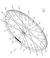
- FIG. 1 a perspective view of a wheel 11 according to a first embodiment of the invention is shown.
- the wheel 11 represented, in particular a front wheel, has a hub 12, a rim 13 and a set of spoke connections 14 between the hub 12 and the rim 13.
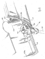
- each spoke connection 14 comprises, in a per se known way, a spoke 141 and an internally threaded element or nipple 142.
- Each spoke 141 typically has a head 143 at a first end, possibly bent at a bend 144 in the case of attachment to a flanged hub, and an outer threading (not visible) at a second end, opposite the first end.
- the bend is normally absent in the case of a non-flanged attachment hub, for example as illustrated in US 2002/0033635 .
- the head 143 of each spoke is housed in a corresponding seat 121 of the hub 12.
- the outer threading of the spoke 141 engages in the inner threading of the internally threaded element 142, which abuts, with the possible interposition of a plate 145, against the rim 13 at a respective seat 131.
- An opening 132 is also shown in the upper bridge 133 of the rim 13, for accessing the internally threaded element 142 through a tool.
- spoke connections 14 it is possible to use any alternative configuration of the spoke connections 14, as is well known in the field, for example in which the internally threaded element 142 engages with the hub 12 and the head 143 of the spoke engages with the rim 13.
- the spoke pattern of the wheel 11 is of the type with spoke connections 14 distributed equally spaced apart along the circumference of the rim 13.
- the spoke pattern of the wheel 11 is furthermore of the even type, since the set of spoke connections 14 comprises sixteen spoke connections, eight on the right hand side of the hub 12 and eight on the left hand side of the hub 12.
- sixteen spoke attachment zones 1501-1516 are defined, comprising respective spoke attachment seats 131 and their thereabouts, alternating with sixteen infraspoke zones 1601-1616.
- the sixteen infraspoke zones 1601-1616 extend along equally long arcs of circumference.
- the rim 13 is of the metal type, made through extrusion of a rod with a suitable cross section, its calendaring and jointing of the ends at a jointing zone 134.
- a housing hole 135 is made for a retaining valve 7 of the air in a pneumatic tire (not shown) externally associated with the rim 13.
- the jointing in the zone 134 is carried out by butt welding of the ends of the extruded and calendared rod.
- fig. 3 which represents a section of the rim 13 with the valve 7 fitted, a pair of solid metal inserts 136 can be seen in an inner chamber of the rim 13, used to allow the ends to be gripped with suitable pincers during welding without the risk of deforming the rim 13.
- the inserts 136 are better illustrated in fig. 4.
- the jointing in the zone 132 can take place through a sleeve 136a, illustrated in fig. 5, inserted with interference, and possibly with a gluing substance, in the inner chamber 137 of the rim 13, as illustrated in fig. 6. Still alternatively, the jointing in the zone 134 can take place through many pins inserted in the wall of the ends of the rim.
- the inserts 136 including the possible welding material, or the other equivalent elements in the jointing zone 134, have a mass m1, which represents a mass discontinuity of the wheel 11, in particular a localized mass increase.
- the valve 7 is typically made from brass and represents another mass discontinuity of the wheel 11, in particular another localized mass increase.
- the localized mass increase due to the presence of the valve 7 minus the local mass reduction due to the presence of the hole 135 for the valve 7 itself shall hereinafter be indicated for the sake of brevity as mass m2 of the valve 7.
- the mass m1 is usually different from the mass m2, so that the wheel 1 is dynamically imbalanced, although the jointing zone 134 and the hole 135 for the valve 7 are diametrically opposite.
- the mass m1 of the joint is greater than the mass m2 of the valve and we shall refer to this assumption in the present embodiment and in the subsequent embodiments.
- the infraspoke zones 1602-1616 each have a mass mz
- the infraspoke zone 1601 comprising the jointing zone 134 has a smaller mass, mz-m3.
- Such an infraspoke zone 1601 with reduced mass is illustrated blackened in fig. 1 for illustrative purposes, but in practice it can have the same coloration as the rest of the rim 13 or a different coloration without it making any difference.
- the mass reduction m3 in the infraspoke zone 1601 is obtained through material-removing working to reduce the average wall thickness of the rim in such a zone 1601.
- the material-removing working can, for example, be mechanical working, in particular milling, chemical etching or spark erosion, and can take place, in particular, as disclosed in the aforementioned documents EP 0 715 001, EP 1 084 868 and European patent application 03425419. 3 not yet published, incorporated herein by reference.
- the reduction in thickness in the infraspoke zone 1601 is illustrated as sharp, different geometries can be used for the transitions from the adjacent spoke attachment zones 1501 and 1516.
- the transitions can develop along a certain length of the rim, i.e. avoiding sharp edges and, on the other hand, creating fillets of a suitable radius of curvature or with a suitable curvilinear progression.
- the removal of material can take place from outside the rim 13 and/or from inside the chamber 137 without it making any difference. What is important for the purposes of the present invention is that the removal of material is such as to provide the required reduction in mass or, in other words, that there is a reduction in average wall thickness.
- infraspoke zones 1602-1616 have the same thickness as the spoke attachment zones 1501-1516, this is not necessary. In particular, it falls within the scope of the present invention to provide a reduction in thickness of all of the infraspoke zones, but greater in size in zone 1601.
- R1, R2 and R3 are substantially equal to each other and that the three component forces all lie along the diameter D common to the jointing zone 134 and the valve 7.
- the first component force F1 in formula (1) i.e. the effect of the joint in the zone 134
- the second component force F2 i.e. the effect of the valve 7
- the third component force F3 i.e. the effect of the mass reduction of the infraspoke zone 1601 with respect to the remaining infraspoke zones 1602-1616.
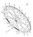
- a wheel 21 according to a second embodiment of the invention is represented in fig. 7 and the relative rim 23 is represented in section, with the valve 7 fitted, in fig. 8.
- the wheel 21 differs from the wheel 11 of fig. 1 in that both of the infraspoke zones 2602 and 2616 adjacent to the infraspoke zone 2601 comprising the jointing zone 234 have a reduced thickness and therefore a reduced mass, mz-m4 and mz-m5 respectively, with respect to the remaining infraspoke zones 2601 and 2603-2615, of mass mz.
- the forces F4 and F5 each form an angle ⁇ of 11.25° (one thirty-second of a revolution) with the diameter D extending between the zone of the joint 234 and the valve 7, the diameter along which the forces F1 and F2 act in opposite directions. If the masses m4 and m5 are the same, the resultant of the two forces F4 and F5 acts along the diameter D, in the opposite direction to the force F1.
- the reduction in mass can be made in the infraspoke zones 2603 and 2615 adjacent to them or else in the infraspoke zones 2604 and 2614 adjacent to the latter, simply by taking the greater angle that the relative forces form with the diameter D common to the jointing zone 234 and to the valve 7 into account in the value of the mass reduction.
- the amount of material to be removed shall therefore be greater than the case of reduction in mass of the infraspoke zones 2602, 2616.
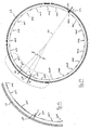
- a wheel 31 according to a third embodiment of the invention is represented in fig. 9 and the relative rim 33 is represented in section, with the valve 7 fitted, in fig. 10.
- a portion of the rim 33 is illustrated magnified in fig. 11.
- the wheel 31 differs from the wheel 11 of fig. 1 in that, apart from the infraspoke zone 3609 comprising the hole 335 for the valve 7 that is of mass mz, not just the infraspoke zone 3601 comprising the jointing zone 334, but also all of the remaining infraspoke zones 3602-3608 and 3610-3616 have a reduced thickness and therefore a reduced mass, in particular mz-m3.
- the same expression (1) of the resultant force is obtained by making just one pair or a few pairs of diametrically opposite infraspoke zones 3602-3608 and 3610-3616 with a reduced thickness, for example with mass mz-m3 or (mz-m3) ⁇ m6.
- a reduction in mass can be made in the infraspoke zones 3605 and 3613, or else in the infraspoke zones 3603, 3611, 3605, 3613, 3607, 3615, etc.
- a wheel 41 according to a fourth embodiment of the invention is schematically represented in fig. 12 and the relative rim 43 is represented in section, with the valve 7 fitted, in fig. 13. A portion of the rim 43 is illustrated magnified in fig. 14.
- the spoke pattern of the wheel 41 is again of the type with the spoke connections 14 distributed equally spaced along the circumference of the rim 43.
- the spoke pattern of the wheel 41 is, however, of the odd type, in that the set of spoke connections 14 comprises twenty-one spoke connections, fourteen on the right hand side of the hub 42 and seven on the left hand side of the hub 42.
- the hole 435 for the valve 7 is not diametrically opposite the zone 434 of the joint, a position in which there is a seat 131 for a spoke connection 14.
- the hole 435 for the valve 7 is therefore at an angle of about 8.5° (one forty-second of a revolution) with respect to the diameter D1 passing through the zone 434 of the joint.
- the invention to reduce or even eliminate the dynamic imbalance of the wheel 41 due to the localized masses m1 of the joint 434 and m2 of the valve 7, it is provided to make a reduction in thickness, and therefore in mass, in all of the infraspoke zones apart from the infraspoke zone 4612 that is situated in a position mirroring the infraspoke zone 4611 comprising the hole 435 for the valve 7 with respect to the diameter D1. Also in Fig. 13, the infraspoke zones 4601-4611 and 4613-4621 of reduced thickness are blackened for merely illustrative purposes.
- the distances R1, R2 and R7 can be considered to be substantially equal to each other.
- the component force F7 and the component force F2 which is the effect of the valve 7, form an angle ⁇ of about 8.5° (one forty-second of a revolution) with the diameter D1 passing through the jointing zone 434.
- spoke attachment zones among the spoke attachment zones 4601-4611 and 4612-4621 at the original thickness or to work them differently. It is possible for example to identify groups of equally spaced infraspoke zones the component forces of which cancel each other out irrespective of the absolute value of their masses, for example the triplets 4303, 4310, 4317 and 4307, 4314, 4321 and similar, or else groups of seven infraspoke zones.
- a wheel 51 in particular a rear wheel, according to a fifth embodiment of the invention is schematically represented in fig. 15 and the relative rim 53 is represented in section, with the valve 7 fitted, in fig. 16.
- the spoke pattern of the wheel 51 comprises twenty-four spoke connections 14 grouped into eight triplets. Eight zones of attachment of groups of spokes 5501-5508 are thus defined, each comprising three spoke attachment seats 131, alternating with eight infraspoke zones 5601-5608. In the zones of attachment of groups of spokes 5501-5508, 24 spoke attachment zones, among which just the zones 5505a, 5505b and 5505c are numbered in Fig. 15 for the sake of brevity, and another sixteen infraspoke zones, of which just the zones 5604a, 5604b, 5605a and 5605b are numbered in Fig. 15 for the sake of brevity, can be defined.
- the spoke pattern of the wheel 51 is therefore of the even type and the hole 535 for the valve 7 is advantageously made diametrically opposite the zone 534 of the joint, along the diameter D.
- the inventive concepts outlined above can be applied considering just the infraspoke zones 5601-5608 between the zones of attachment of groups of spokes, which are those with the longest extent.
- an embodiment is represented corresponding to the third embodiment, in other words a reduction in thickness, and therefore in mass, is made in all of the infraspoke zones 5601-5604 and 5605-5608 among the zones of attachment of groups of spokes, apart from the infraspoke zone 5605 comprising the hole 535 for the valve 7.
- the infraspoke zones of reduced thickness are blackened for merely illustrative purposes.
- the reduction in mass could be made in the infraspoke zones 5604b and 5605a and/or in the infraspoke zones 5604a, 5605b, and/or in the infraspoke zones 5604, 5606.
- a wheel 61 in particular a rear wheel, according to a sixth embodiment of the invention is schematically represented in fig. 17 and the relative rim 63 is represented in section, with the valve 7 fitted, in fig. 18.
- the spoke pattern of the wheel 61 comprises twenty-one spoke connections 14 grouped into seven triplets. Therefore seven zones of attachment of groups of spokes 6501-6507 are defined, each comprising three spoke attachment seats 131, alternating with seven infraspoke zones 6601-6607. In the zones of attachment of groups of spokes 6501-6507, 21 spoke attachment zones, of which just the zones 6504a, 6504b and 6504c are numbered in Fig. 17 for the sake of brevity, and another fourteen infraspoke zones, of which just the zones 6604a and 6604b are numbered in Fig. 17 for the sake of brevity, can be defined.
- the spoke pattern of the wheel 61 is therefore of the odd type and the hole 635 for the valve 7 is not diametrically opposite the zone 634 of the joint, a position in which there is a seat 131 for a spoke connection 14.
- the hole 635 for the valve 7 is therefore at an angle ⁇ of about 25.7° (one fourteenth of a revolution) with respect to the diameter D1 passing through the zone 634 of the joint.
- a joint is indicated using the sleeve 136a of figs. 5 and 6, but it is possible to use the alternative jointing means described above with reference to the first embodiment.
- the infraspoke zones 6601-6607 which represent all of the infraspoke zones between the zones of attachment of groups of spokes, apart from the infraspoke zone 6605 that is in a position mirroring the infraspoke zone 6604 comprising the hole 635 for the valve 7 with respect to the diameter D1.
- the infraspoke zones 6601-6604 and 6606-6607 of reduced thickness are blackened for merely illustrative purposes.
- the resultant of the forces F can once again be expressed by the formula (13) considering, instead of the reduction in mass of the various infraspoke zones, the "additional mass" m7 of the infraspoke zone 6605, in other words the opposite of the mass reduction m3 that is not made in such an infraspoke zone 6605.
- the component force F7 and the component force F2 which are the effect of the valve 7, form an angle ⁇ of about 25.7° (one fourteenth of a revolution) with the diameter D1 passing through the jointing zone 634.
- the reduction in mass could be made in addition in the infraspoke zone 6604a and/or in the infraspoke zone 6604b, so as to compensate in an even more accurate manner for the resultant of the forces F1 and F2 due to the localized mass increases due to the jointing zone 634 and to the valve 7, in the case in which it forms with the diameter D1 a different angle from angle ⁇ .
- Fig. 19 represents a wheel 71, in particular a rear wheel, according to a seventh embodiment of the invention and the relative rim 73 is represented in section, with the valve 7 fitted, in fig. 20. A portion of the rim 73 is illustrated magnified in fig. 21.
- the spoke pattern of the wheel 71 is identical to the one described above with reference to the wheel 51 of the fifth embodiment (Fig. 15), of the even type with twenty-four spoke connections grouped together into triplets. Therefore, eight zones of attachment of groups of spokes 7501-7508 and eight infraspoke zones 7601-7608 are defined. In the zones of attachment of groups of spokes 7501-7508, 24 spoke attachment zones, of which just the zones 7505a, 7505b and 7505c are numbered in Fig. 19 for the sake of brevity, and another sixteen infraspoke zones, of which just the zones 7605a and 7605b are numbered in Fig. 19 for the sake of brevity, can be defined.
- the rim 73 is however made from composite material, made by molding and reticulation or curing of a fibrous material, for example carbon fiber, in a matrix of polymeric material.
- a fibrous material for example carbon fiber
- the details of the manufacture of the rim 73 can be found for example in EP 1 231 077 , incorporated herein by reference.
- the rim 73 is in a single piece, and therefore there isn't any joint.
- valve 7 which is dynamically compensated, according to the invention, through a reduction in mass in some infraspoke zones, obtained through a reduction in thickness.
- Such working can, however, also advantageously be obtained not with subsequent material-removal working, rather directly in the manufacture step of the rim 73, by simply arranging a smaller amount of material in the mould at the desired regions.
- the carbon fiber material in a matrix of polymeric material is available in plies, which are layered to obtain the desired thickness of the various regions of the rim, for example different thicknesses for the lower bridge 139, the upper bridge 133 and the side walls 138a, 138b (Fig. 2).
- a smaller number of plies can therefore be arranged in the mould at those infraspoke zones that, according to the present invention, shall have a reduced mass to at least partially compensate for the localized mass increase due to the valve 7.
- valve 7 is the only localized mass increase present, the reduction in thickness is made, in the present embodiment, in the infraspoke zone 7605 comprising the hole 735 for the valve 7.
- the force F8 and the force F2 i.e. the effect of the localized mass increase due to the valve 7, both act along the diameter D2 passing through the valve 7, according to opposite directions.
- the force F2 of absolute value m2* ⁇ 2 *R2, will be compensated for by a reduction in mass of the infraspoke zone 7605 of 6 grams with respect to the remaining infraspoke zones 7601-7604 and 7606-7608.
- Fig. 22 represents a wheel 81, in particular a rear wheel, according to an eighth embodiment of the invention and the relative rim 83 is represented in section, with the valve 7 fitted, in fig. 23. A portion of the rim 83 is illustrated magnified in fig. 24.
- the spoke pattern of the wheel 81 is identical to the one described above with reference to the wheel 71 of the seventh embodiment (Fig. 19), of the even type with twenty-four spoke connections grouped together in triplets. Therefore, eight spoke attachment zones 8501-8508 and eight infraspoke zones 8601-8608 are defined. In the zones of attachment of groups of spokes 8501-8508, 24 spoke attachment zones, of which just the zones 8505a, 8505b and 8505c are numbered in Fig. 22 for the sake of brevity, and other sixteen infraspoke zones, of which just the zones 8605a and 8605b are numbered in Fig. 22 for the sake of brevity, can be defined.
- the rim 83 is made from single-piece composite material, and therefore there isn't any joint, but there is the localized mass increase represented by the valve 7.
- the compensation according to the invention takes place, like in the seventh embodiment described above, through a reduction in mass made in the infraspoke zone 8605 comprising the hole 835 for the valve 7.
- the reduction in thickness in the infraspoke zone 8605 involves just the two end portions 871 and 872 of the zone itself, whereas in the central portion 873 of the infraspoke zone 8605, where there is the hole 835 for the valve 7, the thickness of the wall of the rim 83 is not reduced or even is increased with respect to the rest of the rim 83. In such a way, the zone of the hole 835 for the valve 7, which represents a weak point of the rim 83, is kept at a thickness suitable for imparting the necessary structural strength to the rim 83.
- rims with a jointing zone like for example metal rims
- this shall be the infraspoke zone adjacent to the position of the heaviest localized mass increase or in the adjacent one of the same extent, in the case of a spoke pattern with groups of spokes.
- the present invention is not limited, in the case of rims with jointing like for example metal rims, by the fact that the zone of the joint is diametrically opposite, or substantially opposite, with respect to the valve.
- the zone of the joint is diametrically opposite, or substantially opposite, with respect to the valve.
- both the infraspoke zone comprising the joint and the infraspoke zone comprising the hole for the valve are of suitably reduced thickness, and/or that pairs of infraspoke zones mirroringly arranged about the infraspoke zone comprising the joint and pairs of infraspoke zones mirroringly arranged about the infraspoke zone comprising the hole for the valve are of suitably reduced thickness.
- Suitable groups comprise two diametrically opposite zones, triplets zones at angles of 120° and the like.
- each zone can have asymmetric geometries, for example to compensate for an asymmetric arrangement of the hole for a valve and/or of the joint in the respective infraspoke zone, or to more accurately compensate for the two localized mass increases, should they not be diametrically opposite.
- the solution of the eighth embodiment, of making three regions of different thickness in the infraspoke zone comprising the hole for a valve can also be applied with metal joints, if the reduction in thickness provided according to the invention must also involve such a zone, like in particular if the valve is heavier than the jointing zone.
Landscapes
- Engineering & Computer Science (AREA)
- Mechanical Engineering (AREA)
- Tires In General (AREA)
- Check Valves (AREA)
- Regulating Braking Force (AREA)
- Heat Treatment Of Articles (AREA)
- Forging (AREA)
- Molds, Cores, And Manufacturing Methods Thereof (AREA)
- Prostheses (AREA)
- Pressure Welding/Diffusion-Bonding (AREA)
Abstract
Description
- The present invention concerns, in general, the field of bicycle spoked wheels, and in particular a rim for a bicycle spoked wheel, a spoked wheel comprising such a rim and a method for manufacturing a rim for bicycle spoked wheel.
- A bicycle spoked wheel conventionally comprises a rim, a hub and a set of spoke connections between the rim and the hub.
- More specifically, for the connection between rim and hub, it is typically provided a spoke having a widened head at a first end, and an outer threading at a second end opposite the first end.
- The widened head of the spoke is received in a suitably shaped seat, usually made at the hub or at a flange thereof. In order to allow the extension of the spoke in the radial or substantially radial direction, a bend is typically provided close to the first end of the spoke. The bend of the spoke at the first end can, however, be left out, for example in the case of use of a hub as described in US 2002/0033635.
- The threading at the second end of the spoke is threadedly coupled in a threaded hole usually made at the rim or, preferably, in a removable connection element of the nipple type or nut type, which abuts at seating holes in the rim, possibly through the interposition of a plate, as illustrated for example in EP 0 936 085.
- Spokes with different attachment means to the rim and to the hub are also known, for example in which the head of the spoke is intended to couple with the rim, and the threading of the spoke is intended to couple with the hub, and the present invention is not limited to any particular type of spoke connection.
- In the present invention and in the attached claims, under the expression "spoke connection" it is meant to indicate the set of a spoke and possible removable connection elements, such as the aforementioned nipple and interposition plate.
- The hub is an element with rotational symmetry with respect to the axis of the bicycle wheel, and the spoke connections are always so distributed along the circumference of the wheel that the center of mass of them as a whole is at the axis of the wheel. More specifically, the spoke connections can be distributed equally spaced apart, or else groups of two or more spoke connections can be distributed equally spaced apart along the rim.
- Due to the different angle of the spoke connections with respect to the median plane of the wheel (camber) between one side and the other of the hub and/or due to a tangential attachment of the spokes to a side of the hub and/or for other reasons in particularly complex spoke patterns, there can be spoke connections of different mass, but still forming regular, with respect to the rotation axis, sub-sets of identical spoke connections. Also in such cases, the center of mass of the set of spoke connections is therefore at the rotation axis of the wheel, in other words the set of spoke connections is balanced with respect to the rotation axis.
- It is well known, for example from EP 0 715 001,
EP 1 084 868 and from European patent application 03425419.3 not yet published, to make rims with a low wall thickness in all of the zones between the spokes, or at least in all of the zones between groups of spokes that are close together, in order to contain the weight of the rim whilst still offering adequate structural strength along the whole rim. - The known geometries of the rims, including those of the documents just mentioned, are such that also the rim is an element with rotational symmetry with respect to the axis of the wheel.
- In first analysis, the wheel is therefore dynamically balanced.
- In practice, there is, however, always a cause for imbalance or mass discontinuity, in particular a localized mass increase, consisting of the retaining valve of the air inside the pneumatic tire, be it of the type with an inner tube, of the tubeless type or of the type with a tubular tire. The valve, fixed in a proper hole formed in the rim, is typically made from brass and has standard dimensions and therefore predetermined weight. The slight lightening caused in the rim by the housing hole provided for the valve itself is not sufficient to compensate for the localized mass increase at the valve. On the contrary, in rims obtained by carbon fiber molding, the localized mass increase at the valve is sometimes accompanied, like in Bora wheels marketed by Campagnolo S.r.l., Italy, by a further increase in mass due to the presence of a greater thickness of the rim in such a zone in order to compensate for the weakening of the rim due to the hole for the valve.
- The cause for imbalance represented by the valve is accompanied, in the case of metal rims, by a second cause. Indeed, metal rims, in particular made from steel or aluminum alloy, are made through a rod extruded according to the desired section of the rim, said rod then being shaped into a circumference through calendaring. The jointing of the ends of the rod is carried out in various ways, all of which however provide for the addition of material and therefore determine a localized mass increase. For example, known methods for carrying out jointing provide for: the insertion with interference of one or more pins in respective holes butt formed in the wall of the ends of the extruded rod; the insertion of a sleeve in an inner chamber of the extruded rod for a certain extent from both ends, possibly with the addition of a gluing substance; the butt welding of the ends, with or without addition of welding material, but in any case with the use of solid metal inserts in the inner chamber of the extruded rod in order to allow for the gripping of the ends with suitable pincers during welding without the risk of deforming the rim.
- Either or both the causes for localized mass increase bring(s) about that the center of mass of the masses does not belong to the rotation axis of the wheel. From the dynamic point of view, the imbalance caused by such localized mass increases brings about an unfavorable instability of the wheel. Moreover, given that the imbalance increases as the speed of the wheel increases, it becomes more dangerous precisely when the travel speed is fast, like going downhill, and, on the contrary, a very stable wheel is needed.
- In the case of metal rims, to reduce the problem of dynamic imbalance, it is known to make the hole for the valve in a position diametrically opposite the joint of the extruded rod. The balancing of the masses in movement thus obtained is, however, insufficient to provide good stability of the wheel since typically the additional mass in the zone of the joint is different from, normally greater than, the mass of the valve body. Moreover, in the case of wheels with odd spoke patterns, sometimes it is not possible to make the hole for the valve in a position diametrically opposite the joint of the extruded rod, but only in an approximately opposite position since the diametrically opposite position is occupied by a spoke or by a group of spokes. The resultant of the forces cannot, therefore, be cancelled out due to the aforementioned mass difference and/or due to the angle that the centrifugal forces due t the two localized mass increases form between them. It has also been attempted to solve the problem of balancing in such rims by sticking a plate at the valve hole. By providing for an additional element, such a provision is however unsatisfactory both from the manufacture point of view and from the point of view of the end product, since, besides increasing the weight of the rim, the plate risks detaching with the use of the bicycle, it is unaesthetic and not aerodynamic.
- The technical problem at the basis of the present invention is to effectively reduce the dynamic imbalance of a bicycle wheel. A more ambitious object is to totally eliminate the dynamic imbalance of a bicycle wheel.
- The technical problem outlined above is solved, according to the invention, by a rim of a bicycle spoked wheel, comprising spoke attachment zones and infraspoke zones, characterized in that said infraspoke zones comprise a first sub-set of infraspoke zones having a first average wall thickness and a second sub-set of infraspoke zones, each infraspoke zone of the second sub-set having a smaller average wall thickness than said first average wall thickness, said infraspoke zones of the second sub-set being distributed to at least partially compensate for at least one localized mass increase of the wheel.
- In the present description and in the attached claims, under average wall thickness it is meant the volume of material of the rim in the zone, divided by the length of the zone.
- The localized mass increases of the wheel can comprise a valve suitable for being coupled with the rim and/or a jointing zone of the rim.
- The second sub-set, i.e. zones of comparatively low thickness, can comprise an infraspoke zone that comprises a first position in which there is a first localized mass increase.
- Alternatively or in addition, the second sub-set can comprise at least one pair of infraspoke zones arranged symmetrically about said first position, in one half of the rim centered about the first position.
- The above also applies in the case in which there is also a second localized mass increase, smaller than said first localized mass increase and arranged at a second position in an infraspoke zone that is substantially diametrically opposite the first position. The two localized mass increases can, indeed, partially compensate each other. Moreover, small deviations from positions not exactly diametrically opposite can be taken into account with an asymmetric progression of the wall thickness of the zone(s) of the second sub-set used for compensation or partial compensation. When there is a first localized mass increase at a first position and a second localized mass increase, smaller than said first localized mass increase and arranged at a second position in an infraspoke zone that is not diametrically opposite the first position, said second sub-set can comprise an infraspoke zone arranged on the same side with respect to the second position with respect to the diameter passing through the first position and in the same half of the rim as the first position.
- In particular, the second sub-set can comprise the infraspoke zone closest to the first position that is of the same extent as the infraspoke zone comprising said first localized mass increase.
- This can, in the case of uniform distribution of the spokes, be the infraspoke zone arranged adjacent to the first position.
- In other embodiments, when there is a first localized mass increase at a first position and a second localized mass increase, smaller than said first localized mass increase and arranged at a second position, the two localized mass increases can be compensated for separately, also in the case in which the first and second localized mass increase are diametrically opposite or substantially opposite. Indeed, in certain cases it may be preferable, to minimize the weight of the rim, to reduce both of the zones involved by the localized mass increases, each by a mass corresponding to the localized mass increase located within it.
- For example, the second sub-set can comprise an infraspoke zone that comprises the first position and an infraspoke zone that comprises the second position.
- Alternatively or in addition, the second sub-set can comprise at least one pair of infraspoke zones symmetrically arranged about said first position, in the half of the rim centered about the first position, and at least one pair of infraspoke zones symmetrically arranged about said second position, in the half of the rim centered about the second position.
- In order to create an advantageously light rim, in the various embodiments the second sub-set can further comprise at least one group of infraspoke zones, the group being balanced with respect to the axis of the rim and therefore being neutral with respect to the compensation of the localized mass increases.
- In particular, said group of zones can comprise one or more pairs of diametrically opposite infraspoke zones.
- In case there are infraspoke zones with different extents, like for example in the case of spoke patterns with groups of spokes, those of the second sub-set can all have the same extent or else a different extent.
- In embodiments that are advantageous since they minimize material-removal working to reduce the thickness of the infraspoke zones of the second sub-set and/or maximize the structural strength of the rim, the second sub-set consists of 1 or 2 infraspoke zones.
- On the other hand, to minimize the weight of the rim, it may be advantageous for said second sub-set to comprise all of the infraspoke zones apart from 1 or 2, or all of the infraspoke zones arranged between groupings of spokes, apart from 1 or 2.
- The infraspoke zones of the second sub-set can have the same average wall thickness, but this is not essential.
- The geometry of the infraspoke zones of the second sub-set can be of various types.
- For example, each infraspoke zone of the second sub-set can have a symmetric or an asymmetric mass distribution.
- Moreover, in each infraspoke zone of the second sub-set, the transitions from the thickness of the adjacent spoke attachment zones can be sharp or develop along a certain length of the rim.
- The reduction in average wall thickness of the infraspoke zones of the second sub-set can be carried out in one or more of the walls of the rim, for example in the one facing towards its center, commonly named lower bridge.
- In order to allow the lightening necessary for compensation whilst still preserving an adequate structural strength, when the second sub-set comprises an infraspoke zone that comprises a hole for a valve, such a zone can have a central region comprising the valve hole and two end regions, the central region having a greater wall thickness than the end regions.
- The infraspoke zones of the first sub-set, i.e. the comparably thick ones, can have an average wall thickness equal to an average wall thickness of the spoke attachment zones, which typically is the maximum thickness of the rim.
- In a second aspect thereof, the invention concerns a bicycle spoked wheel comprising a rim as outlined above.
- In a third aspect thereof, the invention concerns a method of manufacturing a rim of a bicycle spoked wheel, comprising the step of forming a rim having spoke attachment zones and infraspoke zones, characterized in that a first sub-set of said infraspoke zones are formed with a first average wall thickness and a second sub-set of infraspoke zones are formed each with an average wall thickness smaller than the first average wall thickness, said infraspoke zones of the second sub-set being distributed to at least partially compensate for at least one localized mass increase of the wheel.
- The rim can, in particular, be a rim as outlined above.
- In a first variant, the method comprises the step of providing, in a mould for forming the rim, a greater amount of composite material in a matrix of polymeric material in the infraspoke zones of the first sub-set than in the infraspoke zones of the second sub-set.
- In a second variant, the method according to the claim comprises the preliminary step of forming a rim having all of the infraspoke zones of equal average wall thickness and the step of removing material from the second sub-set of infraspoke zones.
- The step of removing material can be carried out through mechanical working, in particular through milling, through chemical etching or through spark erosion.
- The invention shall be better described hereafter with reference to some embodiments and examples, based upon the attached drawings, wherein corresponding elements are designated by similar numbers. In the drawings:
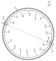
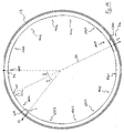
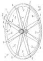
- fig. 1 is a perspective view of a wheel according to a first embodiment of the invention,
- fig. 2 is a partial perspective view of a rim portion having a spoke connection coupled therewith,
- fig. 3 is a section through the rim of the wheel of Fig. 1, with the valve fitted,
- fig. 4 is a perspective view of a pair of inserts for jointing of the rim,
- fig. 5 is a perspective view of a sleeve for jointing of the rim,
- fig. 6 is a cross-sectional view of the sleeve of Fig. 5 inserted in the rim,
- figs. 7 and 8 are views corresponding to figs. 1 and 3 respectively, but relative to a second embodiment,
- figs. 9 and 10 are views corresponding to figs. 1 and 3 respectively, but relative to a third embodiment,
- fig. 11 is a magnified view of a portion of the rim of fig. 10,
- figs. 12 and 13 are views corresponding to figs. 1 and 3 respectively, but relative to a fourth embodiment,
- fig. 14 is a magnified view of a portion of the rim of fig. 13,
- figs. 15 and 16 are views corresponding to figs. 1 and 3 respectively, but relative to a fifth embodiment,
- figs. 17 and 18 are views corresponding to figs. 1 and 3 respectively, but relative to a sixth embodiment,
- figs. 19 and 20 are views corresponding to figs. 1 and 3 respectively, but relative to a seventh embodiment,
- fig. 21 is a magnified view of a portion of the rim of fig. 20,
- figs. 22 and 23 are views corresponding to figs. 1 and 3 respectively, but relative to an eighth embodiment, and
- fig. 24 is a magnified view of a portion of the rim of fig. 23.
- In Fig. 1 a perspective view of a
wheel 11 according to a first embodiment of the invention is shown. Thewheel 11 represented, in particular a front wheel, has ahub 12, arim 13 and a set ofspoke connections 14 between thehub 12 and therim 13. - Also with reference to fig. 2, each spoke
connection 14 comprises, in a per se known way, aspoke 141 and an internally threaded element ornipple 142. Each spoke 141 typically has ahead 143 at a first end, possibly bent at a bend 144 in the case of attachment to a flanged hub, and an outer threading (not visible) at a second end, opposite the first end. The bend is normally absent in the case of a non-flanged attachment hub, for example as illustrated in US 2002/0033635. Thehead 143 of each spoke is housed in acorresponding seat 121 of thehub 12. The outer threading of thespoke 141 engages in the inner threading of the internally threadedelement 142, which abuts, with the possible interposition of aplate 145, against therim 13 at arespective seat 131. Anopening 132 is also shown in theupper bridge 133 of therim 13, for accessing the internally threadedelement 142 through a tool. - However, it is possible to use any alternative configuration of the
spoke connections 14, as is well known in the field, for example in which the internally threadedelement 142 engages with thehub 12 and thehead 143 of the spoke engages with therim 13. - The spoke pattern of the
wheel 11 is of the type withspoke connections 14 distributed equally spaced apart along the circumference of therim 13. - The spoke pattern of the
wheel 11 is furthermore of the even type, since the set ofspoke connections 14 comprises sixteen spoke connections, eight on the right hand side of thehub 12 and eight on the left hand side of thehub 12. Thus, in therim 13 sixteen spoke attachment zones 1501-1516 are defined, comprising respective spokeattachment seats 131 and their thereabouts, alternating with sixteen infraspoke zones 1601-1616. In particular, the sixteen infraspoke zones 1601-1616 extend along equally long arcs of circumference. - The
rim 13 is of the metal type, made through extrusion of a rod with a suitable cross section, its calendaring and jointing of the ends at ajointing zone 134. - In a position diametrically opposite the
jointing zone 134, in the rim 13 ahousing hole 135 is made for a retainingvalve 7 of the air in a pneumatic tire (not shown) externally associated with therim 13. - The jointing in the
zone 134 is carried out by butt welding of the ends of the extruded and calendared rod. In fig. 3, which represents a section of therim 13 with thevalve 7 fitted, a pair of solid metal inserts 136 can be seen in an inner chamber of therim 13, used to allow the ends to be gripped with suitable pincers during welding without the risk of deforming therim 13. Theinserts 136 are better illustrated in fig. 4. - As an alternative to welding and insertion of the
inserts 136, the jointing in thezone 132 can take place through asleeve 136a, illustrated in fig. 5, inserted with interference, and possibly with a gluing substance, in theinner chamber 137 of therim 13, as illustrated in fig. 6. Still alternatively, the jointing in thezone 134 can take place through many pins inserted in the wall of the ends of the rim. - The
inserts 136, including the possible welding material, or the other equivalent elements in thejointing zone 134, have a mass m1, which represents a mass discontinuity of thewheel 11, in particular a localized mass increase. Thevalve 7 is typically made from brass and represents another mass discontinuity of thewheel 11, in particular another localized mass increase. The localized mass increase due to the presence of thevalve 7 minus the local mass reduction due to the presence of thehole 135 for thevalve 7 itself shall hereinafter be indicated for the sake of brevity as mass m2 of thevalve 7. As explained above, the mass m1 is usually different from the mass m2, so that thewheel 1 is dynamically imbalanced, although thejointing zone 134 and thehole 135 for thevalve 7 are diametrically opposite. In most cases, the mass m1 of the joint is greater than the mass m2 of the valve and we shall refer to this assumption in the present embodiment and in the subsequent embodiments. To reduce or even cancel out the imbalance of thewheel 1, i.e. to at least partially compensate for the aforementioned localized mass increases, in therim 13, whereas the infraspoke zones 1602-1616 each have a mass mz, theinfraspoke zone 1601 comprising thejointing zone 134 has a smaller mass, mz-m3. Such aninfraspoke zone 1601 with reduced mass, just like analogous zones in the embodiments described later on, is illustrated blackened in fig. 1 for illustrative purposes, but in practice it can have the same coloration as the rest of therim 13 or a different coloration without it making any difference. - The mass reduction m3 in the
infraspoke zone 1601 is obtained through material-removing working to reduce the average wall thickness of the rim in such azone 1601. - The material-removing working can, for example, be mechanical working, in particular milling, chemical etching or spark erosion, and can take place, in particular, as disclosed in the aforementioned documents EP 0 715 001,
EP 1 084 868 and European patent application 03425419.3 not yet published, incorporated herein by reference. - Although in figures 1 and 3 the reduction in thickness in the
infraspoke zone 1601 is illustrated in the lower bridge 139 (Fig. 2) of therim 13, the reduction in thickness can also or just be carried out in theupper bridge 133 or in aside wall 138a, 138b (Fig. 2). - Moreover, although in figures 1 and 3, just like in the figures relative to the subsequent embodiments, the reduction in thickness in the
infraspoke zone 1601 is illustrated as sharp, different geometries can be used for the transitions from the adjacentspoke attachment zones rim 13 and/or from inside thechamber 137 without it making any difference. What is important for the purposes of the present invention is that the removal of material is such as to provide the required reduction in mass or, in other words, that there is a reduction in average wall thickness. - Finally, it should be noted that, although in figures 1 and 3 the infraspoke zones 1602-1616 have the same thickness as the spoke attachment zones 1501-1516, this is not necessary. In particular, it falls within the scope of the present invention to provide a reduction in thickness of all of the infraspoke zones, but greater in size in
zone 1601. - The resultant of the forces acting in the
wheel 11 in dynamic conditions can be expressed by the following formula (1) where, just like in the subsequent formulae, vector values are indicated in bold type:


wheel 11, R1, R2 and R3 stand for the distances from the center of thewheel 11 of the centers of mass of the mass m1 of the joint 134, of the mass m2 of thevalve 7, and of the mass reduction m3 of the infraspokezone 1601, respectively. - It should be noted that R1, R2 and R3 are substantially equal to each other and that the three component forces all lie along the diameter D common to the
jointing zone 134 and thevalve 7. - Moreover, it should be noted that the first component force F1 in formula (1), i.e. the effect of the joint in the
zone 134, is opposite both the second component force F2, i.e. the effect of thevalve 7, and the third component force F3, i.e. the effect of the mass reduction of the infraspokezone 1601 with respect to the remaining infraspoke zones 1602-1616. - The above formula (1) thus reduces to the scalar expression of the following formula (5):

- Even with very low values of the mass reduction m3 of the infraspoke
zone 1601, for example of 1 or 2 grams, the value of the resultant of the forces F gets close to zero and the dynamic imbalance of thewheel 11 reduces with respect to a wheel in which all of the infraspoke zones are identical to each other, irrespective of their mass mz, a wheel in which the module of the resultant force would be given by the formula (6):
- With a suitable selection of the mass reduction m3 of the infraspoke
zone 1601 with respect to the remaining infraspoke zones 1602-1616, the imbalance due to the presence of the pair ofinserts 136 or other type of joint and to thevalve 7 can be totally cancelled out. Indeed, if the mass reduction is given by the following formula (7):
- Therefore, with such a value of the mass reduction m3, whereas a
rim 13 without avalve 7 as commonly marketed will be imbalanced, once thevalve 7 has been fitted, and also once the spoke connections and the hub have been mounted, thewheel 11 shall be perfectly balanced. In this respect it is worth highlighting that the values of the masses m1 and m2 of thevalve 7 and of the jointing inserts 136 are predetermined and therefore the value m3 of the mass to be removed in theinfraspoke zone 1601 can be easily calculated. - Let us consider a
brass valve 7, of standard size for road bicycles, with a mass of 6 grams, and a joint with a pair of aluminum inserts 136 with a mass of 10 grams. - With a mass reduction m3 of the infraspoke
zone 1601 of 4 grams, thewheel 11 is perfectly balanced. - A
wheel 21 according to a second embodiment of the invention is represented in fig. 7 and therelative rim 23 is represented in section, with thevalve 7 fitted, in fig. 8. - The
wheel 21 differs from thewheel 11 of fig. 1 in that both of theinfraspoke zones infraspoke zone 2601 comprising thejointing zone 234 have a reduced thickness and therefore a reduced mass, mz-m4 and mz-m5 respectively, with respect to the remaininginfraspoke zones 2601 and 2603-2615, of mass mz. - The resultant of the forces acting in the
wheel 21 in dynamic conditions can be expressed by the following formula (8):


wheel 21 of the centers of mass of the mass reduction m4 of the infraspokezone 2602 and of the mass reduction m5 of the infraspokezone 2616, respectively, and the remaining symbols are as described above with reference to the first embodiment. - It should also be noted that the forces F4 and F5 each form an angle α of 11.25° (one thirty-second of a revolution) with the diameter D extending between the zone of the joint 234 and the
valve 7, the diameter along which the forces F1 and F2 act in opposite directions. If the masses m4 and m5 are the same, the resultant of the two forces F4 and F5 acts along the diameter D, in the opposite direction to the force F1. - Even with very limited values of the masses m4 and m5, for example of 1 or 2 grams, the dynamic imbalance of the
wheel 21 is reduced with respect to a wheel in which all of the sixteen infraspoke zones 2601-2616 are identical to each other (formula (6)). - The above formula (8), in the particular case of equal masses m4 and m5 and considering the distances R1, R2, R4 and R5 as equal to each other, reduces to the scalar expression of the following formula (11):

- The imbalance due to the presence of the pair of
inserts 136 or another type of joint in thezone 134, and to thevalve 7 can be totally cancelled out with a suitable selection of values m4 and m5, which cancels out the absolute value of the resultant of the forces F, as expressed by the following formula (12):
- In the conditions illustrated above and with the values provided in example 1 for the masses m1 (10 grams) and m2 (6 grams), one obtains that with masses m4 and m5 of the
infraspoke zones wheel 21 is perfectly balanced. - It should be understood that as an alternative to the
infraspoke zones infraspoke zones infraspoke zones jointing zone 234 and to thevalve 7 into account in the value of the mass reduction. In such a case, the amount of material to be removed shall therefore be greater than the case of reduction in mass of theinfraspoke zones - Again, it should be understood that an intermediate embodiment between the first and second embodiment illustrated above is possible, making mass reductions of suitable values in the
infraspoke zones infraspoke zones infraspoke zones - A
wheel 31 according to a third embodiment of the invention is represented in fig. 9 and therelative rim 33 is represented in section, with thevalve 7 fitted, in fig. 10. A portion of therim 33 is illustrated magnified in fig. 11. - The
wheel 31 differs from thewheel 11 of fig. 1 in that, apart from theinfraspoke zone 3609 comprising thehole 335 for thevalve 7 that is of mass mz, not just theinfraspoke zone 3601 comprising thejointing zone 334, but also all of the remaining infraspoke zones 3602-3608 and 3610-3616 have a reduced thickness and therefore a reduced mass, in particular mz-m3. - It can immediately be recognized that the forces due to two diametrically opposite infraspoke zones of reduced thickness, like for example the
zones - The resultant of the forces acting in the
wheel 31 in dynamic conditions is therefore once again expressed by the above formula (1). - It should be understood that the same expression (1) of the resultant force is obtained by making the infraspoke zones 3602-3608 and 3610-3616 with a thickness that is reduced to a different degree than the infraspoke
zone 3601, for example of mass (mz-m3)±m6. - Moreover, it should be understood that the same expression (1) of the resultant force is obtained by making just one pair or a few pairs of diametrically opposite infraspoke zones 3602-3608 and 3610-3616 with a reduced thickness, for example with mass mz-m3 or (mz-m3)±m6. For example, a reduction in mass can be made in the
infraspoke zones infraspoke zones - A
wheel 41 according to a fourth embodiment of the invention is schematically represented in fig. 12 and therelative rim 43 is represented in section, with thevalve 7 fitted, in fig. 13. A portion of therim 43 is illustrated magnified in fig. 14. - The spoke pattern of the
wheel 41 is again of the type with thespoke connections 14 distributed equally spaced along the circumference of therim 43. - The spoke pattern of the
wheel 41 is, however, of the odd type, in that the set ofspoke connections 14 comprises twenty-one spoke connections, fourteen on the right hand side of the hub 42 and seven on the left hand side of the hub 42. - Therefore, twenty-one spoke attachment zones 4501-4521 and twenty-one infraspoke zones 4601-4621 are defined.
- The
hole 435 for thevalve 7 is not diametrically opposite thezone 434 of the joint, a position in which there is aseat 131 for aspoke connection 14. Thehole 435 for thevalve 7 is therefore at an angle of about 8.5° (one forty-second of a revolution) with respect to the diameter D1 passing through thezone 434 of the joint. - According to the invention, to reduce or even eliminate the dynamic imbalance of the
wheel 41 due to the localized masses m1 of the joint 434 and m2 of thevalve 7, it is provided to make a reduction in thickness, and therefore in mass, in all of the infraspoke zones apart from theinfraspoke zone 4612 that is situated in a position mirroring theinfraspoke zone 4611 comprising thehole 435 for thevalve 7 with respect to the diameter D1. Also in Fig. 13, the infraspoke zones 4601-4611 and 4613-4621 of reduced thickness are blackened for merely illustrative purposes. - The resultant of the forces F can more easily be expressed, for the present embodiment, considering, instead of the reduction in mass of the various infraspoke zones, the "additional mass" m7 of the infraspoke
zone 4612, in other words the opposite of the mass reduction m3 that is not made in such aninfraspoke zone 4612, as in the following formula (13):

wheel 41 of the center of mass of the mass m7 and the remaining symbols are as discussed above with reference to the first embodiment. - The distances R1, R2 and R7 can be considered to be substantially equal to each other.
- The component force F7 and the component force F2, which is the effect of the
valve 7, form an angle β of about 8.5° (one forty-second of a revolution) with the diameter D1 passing through thejointing zone 434. - Also in the case of the
wheel 41, it is possible to reduce the dynamic imbalance with respect to a wheel in which all of the twenty-one infraspoke zones are identical to each other even with very low values, for example of 1 or 2 grams, of the reduction in mass of the zones 4601-4611 and 4613-4621 and, with suitably selected values of such a reduction in mass, to eliminate such an imbalance. - In the case in which the resultant of the forces F1 and F2 due to the localized mass increases due to the
jointing zone 434 and the valve 7 - the resultant to be compensated for through the force F7 - forms a different angle with the diameter D1 from the angle β, it is possible to displace the center of mass of the "additional mass" m7 with suitably asymmetric working of the infraspokezone 4602 and/or by further providing a suitably asymmetric reduction in thickness of the infraspokezone 4612 substantially diametrically opposite it and/or by arranging thehole 435 for the valve in a decentered position in theinfraspoke zone 4611. - Let us consider a
brass valve 7, of a standard size for road bicycles, with a mass of 6 grams and a joint with a pair of aluminum inserts 136 with a mass of 7 grams. - With an "additional mass" m7 of the infraspoke
zone 4612 of 2.6 grams, the resultant of the forces F is substantially zero and therefore thewheel 41 is substantially balanced. - Also in the case of the embodiment just described, it will be understood that it is possible to leave other spoke attachment zones among the spoke attachment zones 4601-4611 and 4612-4621 at the original thickness or to work them differently. It is possible for example to identify groups of equally spaced infraspoke zones the component forces of which cancel each other out irrespective of the absolute value of their masses, for example the
triplets 4303, 4310, 4317 and 4307, 4314, 4321 and similar, or else groups of seven infraspoke zones. - A
wheel 51, in particular a rear wheel, according to a fifth embodiment of the invention is schematically represented in fig. 15 and therelative rim 53 is represented in section, with thevalve 7 fitted, in fig. 16. - The spoke pattern of the
wheel 51 comprises twenty-fourspoke connections 14 grouped into eight triplets. Eight zones of attachment of groups of spokes 5501-5508 are thus defined, each comprising three spokeattachment seats 131, alternating with eight infraspoke zones 5601-5608. In the zones of attachment of groups of spokes 5501-5508, 24 spoke attachment zones, among which just the zones 5505a, 5505b and 5505c are numbered in Fig. 15 for the sake of brevity, and another sixteen infraspoke zones, of which just the zones 5604a, 5604b, 5605a and 5605b are numbered in Fig. 15 for the sake of brevity, can be defined. - The spoke pattern of the
wheel 51 is therefore of the even type and thehole 535 for thevalve 7 is advantageously made diametrically opposite thezone 534 of the joint, along the diameter D. - The fact that the spokes are grouped together and therefore the infraspoke zones have different extents makes no difference to the application of the inventive concepts.
- Thus, it is possible to reduce or even eliminate the dynamic imbalance of the
wheel 51 due to the localized masses m1 of the joint 534 and m2 of thevalve 7 in a conceptually identical manner to the first, to the second or to the third embodiments described above, with all of the generalizations thereof being valid. - According to a first approach, the inventive concepts outlined above can be applied considering just the infraspoke zones 5601-5608 between the zones of attachment of groups of spokes, which are those with the longest extent.
- As an example, in the
wheel 51 of figs. 15 and 16, an embodiment is represented corresponding to the third embodiment, in other words a reduction in thickness, and therefore in mass, is made in all of the infraspoke zones 5601-5604 and 5605-5608 among the zones of attachment of groups of spokes, apart from theinfraspoke zone 5605 comprising thehole 535 for thevalve 7. Also in Fig. 15, the infraspoke zones of reduced thickness are blackened for merely illustrative purposes. - It should also be noted that in fig. 16 a joint is indicated using the
sleeve 136a of figs. 5 and 6, but also in this case it is possible to use the alternative jointing means described above with reference to the first embodiment. - The resultant of the forces F is once again expressed by formula (1) and it is possible to obtain a perfect balance, as in the following example.
- Let us consider a
brass valve 7, of a standard size for road bicycles, with a mass of 6 grams and a joint with analuminum sleeve 136a with a mass of 11 grams. - With a value of mass reduction m3 of the infraspoke zone 5601 (and of the infraspoke zones 5602-5604 and 5606-5608) of 5 grams, the resultant of the forces F is zero and therefore the
wheel 41 is perfectly balanced. - According to a different approach, the inventive concepts outlined above, in their most general sense, can however be applied also considering the infraspoke zones 5605a, 5605b and analogous ones.
- Merely as an example, in a solution corresponding to the second embodiment, the reduction in mass could be made in the infraspoke zones 5604b and 5605a and/or in the infraspoke zones 5604a, 5605b, and/or in the
infraspoke zones - A
wheel 61, in particular a rear wheel, according to a sixth embodiment of the invention is schematically represented in fig. 17 and therelative rim 63 is represented in section, with thevalve 7 fitted, in fig. 18. - The spoke pattern of the
wheel 61 comprises twenty-onespoke connections 14 grouped into seven triplets. Therefore seven zones of attachment of groups of spokes 6501-6507 are defined, each comprising three spokeattachment seats 131, alternating with seven infraspoke zones 6601-6607. In the zones of attachment of groups of spokes 6501-6507, 21 spoke attachment zones, of which just the zones 6504a, 6504b and 6504c are numbered in Fig. 17 for the sake of brevity, and another fourteen infraspoke zones, of which just thezones 6604a and 6604b are numbered in Fig. 17 for the sake of brevity, can be defined. - The spoke pattern of the
wheel 61 is therefore of the odd type and thehole 635 for thevalve 7 is not diametrically opposite thezone 634 of the joint, a position in which there is aseat 131 for aspoke connection 14. Thehole 635 for thevalve 7 is therefore at an angle γ of about 25.7° (one fourteenth of a revolution) with respect to the diameter D1 passing through thezone 634 of the joint. - Also in fig. 18 a joint is indicated using the
sleeve 136a of figs. 5 and 6, but it is possible to use the alternative jointing means described above with reference to the first embodiment. - Also in the case of a spoke pattern with an odd number of triplets (or of groupings of another number of spoke connections), the fact that the spokes are grouped together and therefore the infraspoke zones have different extents makes no difference to the application of the inventive concepts.
- Thus, it is possible to reduce or even eliminate the dynamic imbalance of the
wheel 61 due to the localized masses m1 of the joint 634 and m2 of thevalve 7 in an conceptually identical manner to the fourth embodiment described above, with all of the generalizations thereof being valid, both considering just the infraspoke zones 6601-6607 between the zones of attachment of groups of spokes, with longer extent, and considering also theinfraspoke zones 6604a, 6604b and analogous ones. - Just as an example, in the
wheel 61 of figs. 17 and 18, to reduce or even eliminate the dynamic imbalance of thewheel 61 due to the localized masses m1 of the joint 634 and m2 of thevalve 7, it is provided to make a reduction in thickness, and therefore in mass, in the infraspoke zones 6601-6607, which represent all of the infraspoke zones between the zones of attachment of groups of spokes, apart from theinfraspoke zone 6605 that is in a position mirroring theinfraspoke zone 6604 comprising thehole 635 for thevalve 7 with respect to the diameter D1. Also in Fig. 17, the infraspoke zones 6601-6604 and 6606-6607 of reduced thickness are blackened for merely illustrative purposes. - The resultant of the forces F can once again be expressed by the formula (13) considering, instead of the reduction in mass of the various infraspoke zones, the "additional mass" m7 of the infraspoke
zone 6605, in other words the opposite of the mass reduction m3 that is not made in such aninfraspoke zone 6605. - The component force F7 and the component force F2, which are the effect of the
valve 7, form an angle Υ of about 25.7° (one fourteenth of a revolution) with the diameter D1 passing through thejointing zone 634. - Also in the case of the
wheel 61, it is possible to reduce the dynamic imbalance with respect to a wheel in which all of the seven infraspoke zones are identical to each other even with very low values, for example 1 or 2 grams, of the reduction in mass of the zones 6601-6604 and 6606-6607 and, with suitably selected values of such a reduction in mass, to substantially eliminate such an imbalance. - Let us consider a
brass valve 7, of a standard size for road bicycles, with a mass of 6 grams and a joint with analuminum sleeve 136a with a mass of 11 grams. - With a mass reduction m3 of all of the infraspoke zones 6601-6604 and 6606-6607 extending between zones of attachment of groups of spokes, apart from the
infraspoke zone 6605, of 6 grams, the resultant of the forces F is substantially zero and therefore thewheel 61 is substantially balanced. - Just as another example, the reduction in mass could be made in addition in the
infraspoke zone 6604a and/or in the infraspoke zone 6604b, so as to compensate in an even more accurate manner for the resultant of the forces F1 and F2 due to the localized mass increases due to thejointing zone 634 and to thevalve 7, in the case in which it forms with the diameter D1 a different angle from angle Υ. - In the previous embodiments the assumption that the mass m1 of the joint is greater than the mass m2 of the valve was always considered, since this is the most common situation. Those skilled in the art shall, however, understand that in case the mass m1 of the joint is, on the other hand, lower than the mass m2 of the valve, the solutions described up to now shall be applied mutatis mutandis.
- Of course, it will also be understood that what stated above with reference to the first embodiment concerning the type and geometry of the material-removal working is valid for all of the other embodiments.
- Fig. 19 represents a
wheel 71, in particular a rear wheel, according to a seventh embodiment of the invention and therelative rim 73 is represented in section, with thevalve 7 fitted, in fig. 20. A portion of therim 73 is illustrated magnified in fig. 21. - The spoke pattern of the
wheel 71 is identical to the one described above with reference to thewheel 51 of the fifth embodiment (Fig. 15), of the even type with twenty-four spoke connections grouped together into triplets. Therefore, eight zones of attachment of groups of spokes 7501-7508 and eight infraspoke zones 7601-7608 are defined. In the zones of attachment of groups of spokes 7501-7508, 24 spoke attachment zones, of which just the zones 7505a, 7505b and 7505c are numbered in Fig. 19 for the sake of brevity, and another sixteen infraspoke zones, of which just the zones 7605a and 7605b are numbered in Fig. 19 for the sake of brevity, can be defined. - In the
wheel 71, therim 73 is however made from composite material, made by molding and reticulation or curing of a fibrous material, for example carbon fiber, in a matrix of polymeric material. The details of the manufacture of therim 73 can be found for example inEP 1 231 077, incorporated herein by reference. Therim 73 is in a single piece, and therefore there isn't any joint. - Also in the case of the
rim 73, there is nevertheless a localized mass discontinuity or increase, represented by thevalve 7, which is dynamically compensated, according to the invention, through a reduction in mass in some infraspoke zones, obtained through a reduction in thickness. - The reduction in thickness, in the case of rims made from composite material, can be obtained with subsequent material-removal working, in the manner and according to the geometries indicated above.
- Such working can, however, also advantageously be obtained not with subsequent material-removal working, rather directly in the manufacture step of the
rim 73, by simply arranging a smaller amount of material in the mould at the desired regions. Regarding this, it should be noted that, as described for example in theaforementioned EP 1 231 077, the carbon fiber material in a matrix of polymeric material is available in plies, which are layered to obtain the desired thickness of the various regions of the rim, for example different thicknesses for thelower bridge 139, theupper bridge 133 and theside walls 138a, 138b (Fig. 2). A smaller number of plies can therefore be arranged in the mould at those infraspoke zones that, according to the present invention, shall have a reduced mass to at least partially compensate for the localized mass increase due to thevalve 7. - Given that in the case of a single-
piece rim 73, thevalve 7 is the only localized mass increase present, the reduction in thickness is made, in the present embodiment, in theinfraspoke zone 7605 comprising thehole 735 for thevalve 7. - The resultant of the centrifugal forces acting in the
wheel 71 in dynamic conditions can be expressed by the following formula (15):

wheel 71 of the center of mass of the mass reduction m8 of the infraspokezone 7605 with respect to the remaining infraspoke zones 7601-7604 and 7606-7608 similarly extending between zones of groups of spokes, and the remaining symbols are as discussed above. - It should be noted that the force F8 and the force F2, i.e. the effect of the localized mass increase due to the
valve 7, both act along the diameter D2 passing through thevalve 7, according to opposite directions. - Also in the case of the
wheel 71, it is therefore possible to reduce the dynamic imbalance with respect to a wheel in which all of the eight infraspoke zones 7601-7608 extending between zones of groups of spokes are identical to each other even with very low values, for example 1 or 2 grams, of the reduction in mass of the infraspokezone 7605 and, with a suitably selected value of such a mass, to eliminate such an imbalance. - Indeed, in case one selects:

rim 73 and thevalve 7 is perfectly balanced, just like thewheel 71. - Let us consider a
brass valve 7, of a standard size for road bicycles, with a weight of 6 grams, and let us neglect the effects of thehole 735 for thevalve 7. - The force F2, of absolute value m2*ω2*R2, will be compensated for by a reduction in mass of the infraspoke
zone 7605 of 6 grams with respect to the remaining infraspoke zones 7601-7604 and 7606-7608. - Fig. 22 represents a
wheel 81, in particular a rear wheel, according to an eighth embodiment of the invention and therelative rim 83 is represented in section, with thevalve 7 fitted, in fig. 23. A portion of therim 83 is illustrated magnified in fig. 24. - The spoke pattern of the
wheel 81 is identical to the one described above with reference to thewheel 71 of the seventh embodiment (Fig. 19), of the even type with twenty-four spoke connections grouped together in triplets. Therefore, eight spoke attachment zones 8501-8508 and eight infraspoke zones 8601-8608 are defined. In the zones of attachment of groups of spokes 8501-8508, 24 spoke attachment zones, of which just thezones - Also in the
wheel 81, therim 83 is made from single-piece composite material, and therefore there isn't any joint, but there is the localized mass increase represented by thevalve 7. - The compensation according to the invention takes place, like in the seventh embodiment described above, through a reduction in mass made in the
infraspoke zone 8605 comprising thehole 835 for thevalve 7. - In the case of the
rim 83, however, the reduction in thickness in theinfraspoke zone 8605 involves just the twoend portions central portion 873 of the infraspokezone 8605, where there is thehole 835 for thevalve 7, the thickness of the wall of therim 83 is not reduced or even is increased with respect to the rest of therim 83. In such a way, the zone of thehole 835 for thevalve 7, which represents a weak point of therim 83, is kept at a thickness suitable for imparting the necessary structural strength to therim 83. - The resultant of the forces acting in the
wheel 81 in dynamic conditions can again be expressed by formula (15) and the mass reduction m8 necessary for the perfect balance of therim 83, once thevalve 7 has been fitted, is again expressed by formula (17), since the center of mass of the mass reduction is again along the diameter D2 passing through thevalve 7, wherein the value of R8 is slightly smaller than the value of R8 of example 6. - Of course, it is possible, as an alternative to the seventh and eighth embodiments described above, to reduce or eliminate the imbalance of the
wheels zone 7605, in a pair of or in a few pairs of infraspoke zones arranged symmetrically with respect to theinfraspoke zone 7605, like for example in theinfraspoke zones - Moreover, it is possible to make further reductions in mass, by the same or a different amount, in pairs of diametrically opposite infraspoke zones, for example in the
infraspoke zones infraspoke zones infraspoke zone 7601 diametrically opposite theinfraspoke zone 7605, in a conceptually analogous manner to the third embodiment. - More generally, it should be understood that, in the case of single piece rims of whatever type of spoke pattern, be it single or with groups of spoke connections, and also in the case of odd spoke patterns, it is always possible to completely eliminate the dynamic imbalance by making the reduction in thickness in the infraspoke zone comprising the hole for the valve and/or in at least one pair of infraspoke zones arranged symmetrically with respect to it, in the half of the rim centered about the hole for the valve.
- In the case of rims with a jointing zone like for example metal rims, it should be understood that it is in general possible to provide any number of infraspoke zones with reduced mass, so that they prevail in the half of the rim centered about the greatest localized mass increase, usually the zone of the joint.
- When the zone of the joint and the hole for the valve are diametrically opposite or in any case in diametrically opposite infraspoke zones, the general concept outlined above can be applied, considering that the two localized mass increases are the equivalent to just one arranged in the point of the heaviest one. Therefore, with any type of spoke pattern, be it single or with groups of spoke connections, and also in the case of odd spoke patterns, it is always possible to completely eliminate the dynamic imbalance by making the reduction in thickness in the infraspoke zone comprising the heaviest mass increase and/or in at least one pair of infraspoke zones arranged symmetrically with respect to it, in the same half of the rim. Small deviations from positions that are not exactly diametrically opposite of the jointing zone and of the hole for the valve can be taken into account with an asymmetric progression in the wall thickness of the zone(s) of the second sub-set involved by the reduction in thickness.
- When the zone of the joint and the hole for the valve are not diametrically opposite, it is possible to make a reduction in mass in at least one infraspoke zone arranged on the same side with respect to the position of the lightest localized mass increase, with respect to the diameter passing through the position of the heaviest localized mass increase and in the half of the rim centered about the latter.
- In particular, this shall be the infraspoke zone adjacent to the position of the heaviest localized mass increase or in the adjacent one of the same extent, in the case of a spoke pattern with groups of spokes.
- However, it must be clear that the present invention is not limited, in the case of rims with jointing like for example metal rims, by the fact that the zone of the joint is diametrically opposite, or substantially opposite, with respect to the valve. Those skilled in the art will understand that in case such elements are closer together it shall be sufficient to increase the reduction in mass of the infraspoke zone(s) of reduced mass, which shall be arranged in a suitable position, closer to the greatest localized mass increase, usually the joint.
- It is also possible to provide for a separate compensation of the localized mass increases represented by the jointing zone and by the valve, for example by providing that both the infraspoke zone comprising the joint and the infraspoke zone comprising the hole for the valve are of suitably reduced thickness, and/or that pairs of infraspoke zones mirroringly arranged about the infraspoke zone comprising the joint and pairs of infraspoke zones mirroringly arranged about the infraspoke zone comprising the hole for the valve are of suitably reduced thickness.
- Besides the general criteria outlined above, it shall also be possible to make further reductions in at least one group of infraspoke zones, said group having a rotational symmetry, since in such a case the sum of the masses of the group is zero. Suitable groups comprise two diametrically opposite zones, triplets zones at angles of 120° and the like.
- Wishing to favor the reduction in weight of the rim, it is therefore possible substantially in all conditions to achieve a rim having just one or two infraspoke zones integral or of high thickness, or just one or two of the infraspoke zones extending between groups of spokes.
- It is worth once again highlighting that the reductions in thickness of each zone can have asymmetric geometries, for example to compensate for an asymmetric arrangement of the hole for a valve and/or of the joint in the respective infraspoke zone, or to more accurately compensate for the two localized mass increases, should they not be diametrically opposite.
- Moreover, the solution of the eighth embodiment, of making three regions of different thickness in the infraspoke zone comprising the hole for a valve, can also be applied with metal joints, if the reduction in thickness provided according to the invention must also involve such a zone, like in particular if the valve is heavier than the jointing zone.
Claims (35)
- Rim (13; 23; 33; 43; 53; 63; 73; 83) of a bicycle spoked wheel (11; 21; 31; 41; 51; 61; 71; 81), comprising spoke attachment zones (1501-1516; 2501-2516; 3501-3516; 4501-4521; 5501-5508; 5505a-c; 6501-6507, 6504a-c; 7501-7508, 7505a-c; 8501-8508, 8505a-c) and infraspoke zones (1601-1616; 2601-2616; 3601-3616; 4601-4621; 5601-5608, 5605a-b; 6601-6607, 6604a-b; 7601-7608, 7605a-b; 8601-8608, 8605a-c), characterized in that said infraspoke zones comprise a first sub-set of infraspoke zones having a first average wall thickness and a second sub-set of infraspoke zones (1601; 2602, 2616; 3601-3608, 3610-3616; 4601-4611, 4612-4621; 5601-5604, 5606-5608; 6601-6603, 6605-6607; 7605; 8605), each infraspoke zone of the second sub-set having a lower average wall thickness than said first average wall thickness, said infraspoke zones of the second sub-set being distributed to at least partially compensate for at least one localized mass increase (7; 134, 234, 334, 434, 534, 634, 734, 834) of the wheel.
- Rim according to claim 1, wherein said at least one localized mass increase comprises a first localized mass increase at a first position and said second sub-set comprises an infraspoke zone that comprises the first position.
- Rim according to claim 1 or 2, wherein said at least one localized mass increase comprises a first localized mass increase at a first position and said second sub-set comprises at least one pair of infraspoke zones arranged symmetrically about said first position, in a half of the rim centered about the first position.
- Rim according to claim 2 or 3, wherein said at least one localized mass increase further comprises a second localized mass increase, smaller than said first localized mass increase and arranged at a second position in an infraspoke zone substantially diametrically opposite the first position.
- Rim according to claim 1, wherein said at least one localized mass increase comprises a first localized mass increase at a first position and a second localized mass increase, smaller than said first localized mass increase and arranged at a second position in an infraspoke zone that is not diametrically opposite the first position, and said second sub-set comprises an infraspoke zone arranged on the same side with respect to the second position with respect to the diameter passing through the first position and in a half of the rim centered about the first position.
- Rim according to claim 5, wherein said second sub-set comprises the infraspoke zone closest to the first position that is of the same extent as the infraspoke zone comprising said first localized mass increase.
- Rim according to claim 6, wherein said second sub-set comprises the infraspoke zone arranged adjacent to the first position.
- Rim according to claim 1, wherein said at least one localized mass increase comprises a first localized mass increase at a first position and a second localized mass increase, smaller than said first localized mass increase and arranged at a second position, and said second sub-set comprises an infraspoke zone that comprises the first position and an infraspoke zone that comprises the second position.
- Rim according to claim 1 or 8, wherein said at least one localized mass increase comprises a first localized mass increase at a first position and a second localized mass increase, smaller than said first localized mass increase and arranged at a second position, and said second sub-set comprises at least one pair of infraspoke zones symmetrically arranged about said first position, in a half of the rim centered about the first position, and at least one pair of infraspoke zones symmetrically arranged about said second position, in a half of the rim centered about the second position.
- Rim according to one of claims 2-9, wherein said second sub-set further comprises at least one group of infraspoke zones, the group being balanced with respect to the axis of the rim.
- Rim according to claim 10, wherein said at least one group of zones comprises at least one pair of diametrically opposite infraspoke zones.
- Rim according to any one of the previous claims, wherein the infraspoke zones of the second sub-set have the same extent.
- Rim according to any one of the previous claims, wherein the infraspoke zones of the second sub-set have a different extent.
- Rim according to claim 1, wherein said second sub-set consists of 1 or 2 infraspoke zones.
- Rim according to claim 1, wherein said second sub-set comprises all of the infraspoke zones apart from 1 or 2.
- Rim according to claim 1, wherein said second sub-set comprises all of the infraspoke zones arranged between groupings of spokes, apart from 1 or 2.
- Rim according to any one of the previous claims, wherein all of the infraspoke zones of the second sub-set have a same average wall thickness.
- Rim according to any one of the previous claims, wherein each infraspoke zone of the second sub-set has a symmetric mass distribution.
- Rim according to any one of claims 1-18, wherein at least one infraspoke zone of the second sub-set has an asymmetric mass distribution.
- Rim according to any one of the previous claims, wherein, in each infraspoke zone of the second sub-set, the transitions from the thickness of the adjacent spoke attachment zones are sharp.
- Rim according to one of claims 1-19, wherein, in each infraspoke zone of the second sub-set, the transitions from the thickness of the adjacent spoke attachment zones develop along a certain length of the rim.
- Rim according to one of the previous claims, wherein the reduction in average wall thickness of the infraspoke zones of the second sub-set is in a lower bridge of the rim.
- Rim according to claim 21, wherein said second sub-set comprises an infraspoke zone that comprises a hole for a valve and said zone has a central region comprising the valve hole and two end regions, the central region having a greater wall thickness than the end regions.
- Rim according to claim 1, wherein said first average wall thickness is equal to an average wall thickness of the spoke attachment zones.
- Rim according to claim 1, wherein said at least one localized mass increase of the wheel comprises a valve suitable for being coupled with the rim.
- Rim according to claim 1, wherein said at least one localized mass increase of the wheel comprises a jointing zone of the rim.
- Bicycle spoked wheel comprising a rim according to any one of claims 1 to 26.
- Method of manufacturing a rim of a bicycle spoked wheel, comprising the step of forming a rim having spoke attachment zones and infraspoke zones, characterized in that a first sub-set of said infraspoke zones are formed with a first average wall thickness and a second sub-set of infraspoke zones are each formed with a lower average wall thickness than the first average wall thickness, said infraspoke zones of the second sub-set being distributed to at least partially compensate for at least one localized mass increase of the wheel.
- Method according to claim 28, comprising the step of providing, in a mould for forming the rim, a greater amount of composite material in a matrix of polymeric material in the infraspoke zones of the first sub-set than in the infraspoke zones of the second sub-set.
- Method according to claim 28 or 29, characterized in that it comprises the preliminary step of forming a rim having all of the infraspoke zones of equal average wall thickness and the step of removing material from the second sub-set of infraspoke zones.
- Method according to claim 30, wherein said material removal step is carried out through mechanical working.
- Method according to claim 31, wherein said mechanical working is milling.
- Method according to claim 30, wherein said material removal step is carried out through chemical etching.
- Method according to claim 30, wherein said material removal step is carried out through spark erosion.
- Method according to one of claims 28-34, wherein the rim is according to one of claims 1-26.
Priority Applications (9)
| Application Number | Priority Date | Filing Date | Title |
|---|---|---|---|
| EP04425653A EP1629997B1 (en) | 2004-08-31 | 2004-08-31 | Rim for a bicycle spoked wheel, wheel and manufacturing method |
| AT04425653T ATE383960T1 (en) | 2004-08-31 | 2004-08-31 | RIM FOR A BICYCLE SPOKE WHEEL, WHEEL AND METHOD FOR MANUFACTURING |
| DE602004011339T DE602004011339T2 (en) | 2004-08-31 | 2004-08-31 | Rim for a bicycle spoked wheel, wheel and method of manufacture |
| PT04425653T PT1629997E (en) | 2004-08-31 | 2004-08-31 | Rim for a bicycle spoked wheel, wheel and manufacturing method |
| US11/216,611 US8007052B2 (en) | 2004-08-31 | 2005-08-31 | Rim for a spoked bicycle wheel, wheel and manufacturing method |
| TW094129965A TWI398367B (en) | 2004-08-31 | 2005-08-31 | Rim for a bicycle spoked wheel, wheel and manufacturing method |
| CN200510096673A CN100593477C (en) | 2004-08-31 | 2005-08-31 | Rim of spoked wheel, wheel for bicycle and manufacturing method |
| JP2005251583A JP4902154B2 (en) | 2004-08-31 | 2005-08-31 | Bicycle spoked wheel rim, wheel and manufacturing method |
| JP2011197706A JP2012006594A (en) | 2004-08-31 | 2011-09-09 | Rim for spoked bicycle wheel, wheel and manufacturing method |
Applications Claiming Priority (1)
| Application Number | Priority Date | Filing Date | Title |
|---|---|---|---|
| EP04425653A EP1629997B1 (en) | 2004-08-31 | 2004-08-31 | Rim for a bicycle spoked wheel, wheel and manufacturing method |
Publications (2)
| Publication Number | Publication Date |
|---|---|
| EP1629997A1 true EP1629997A1 (en) | 2006-03-01 |
| EP1629997B1 EP1629997B1 (en) | 2008-01-16 |
Family
ID=34932741
Family Applications (1)
| Application Number | Title | Priority Date | Filing Date |
|---|---|---|---|
| EP04425653A Expired - Lifetime EP1629997B1 (en) | 2004-08-31 | 2004-08-31 | Rim for a bicycle spoked wheel, wheel and manufacturing method |
Country Status (8)
| Country | Link |
|---|---|
| US (1) | US8007052B2 (en) |
| EP (1) | EP1629997B1 (en) |
| JP (2) | JP4902154B2 (en) |
| CN (1) | CN100593477C (en) |
| AT (1) | ATE383960T1 (en) |
| DE (1) | DE602004011339T2 (en) |
| PT (1) | PT1629997E (en) |
| TW (1) | TWI398367B (en) |
Cited By (4)
| Publication number | Priority date | Publication date | Assignee | Title |
|---|---|---|---|---|
| US7874625B2 (en) | 2008-09-04 | 2011-01-25 | Trek Bicycle Corporation | Bicycle wheel assembly having dissimilar lateral spoke lacings |
| FR2985219A1 (en) * | 2012-01-04 | 2013-07-05 | Mavic Sas | RIM FOR CYCLE WHEEL AND METHOD FOR MANUFACTURING THE SAME |
| FR2985218A1 (en) * | 2012-01-04 | 2013-07-05 | Mavic Sas | RIM FOR CYCLE WHEEL AND METHOD FOR MANUFACTURING THE SAME |
| FR2985217A1 (en) * | 2012-01-04 | 2013-07-05 | Mavic Sas | RIM FOR CYCLE WHEEL AND METHOD FOR MANUFACTURING THE SAME |
Families Citing this family (18)
| Publication number | Priority date | Publication date | Assignee | Title |
|---|---|---|---|---|
| ATE390297T1 (en) | 2002-11-08 | 2008-04-15 | Campagnolo Srl | METHOD FOR PRODUCING A SPOKE WHEEL FOR BICYCLES |
| EP1491362B1 (en) | 2003-06-26 | 2008-04-09 | Campagnolo S.r.l. | Lightened rim for a bicycle wheel and method for manufacturing such a rim |
| ATE400453T1 (en) | 2003-08-11 | 2008-07-15 | Campagnolo Srl | COMPOSITE BICYCLE RIM AND METHOD FOR PRODUCING SAME |
| ITMI20072231A1 (en) | 2007-11-26 | 2009-05-27 | Campagnolo Srl | RIM FOR BICYCLE WHEEL AND BICYCLE WHEEL INCLUDING SUCH RIM |
| ITMI20072232A1 (en) * | 2007-11-26 | 2009-05-27 | Campagnolo Srl | RIM FOR BICYCLE WHEEL AND BICYCLE WHEEL INCLUDING SUCH RIM |
| ATE509779T1 (en) | 2008-03-14 | 2011-06-15 | Campagnolo Srl | WHEEL RIM MADE OF COMPOSITE MATERIAL FOR A TUBELESS BICYCLE WHEEL AND A TUBELESS BICYCLE EQUIPPED WITH SUCH A WHEEL RIM |
| US8449044B2 (en) * | 2010-09-27 | 2013-05-28 | Shimano Components (Malaysia) Sdn. Bhd. | Bicycle rim |
| US9182009B2 (en) * | 2012-10-29 | 2015-11-10 | Wheel Pros, Llc | Reduced weight wheel configured for use with valve stem and or tire sensor |
| US10202162B2 (en) | 2014-03-12 | 2019-02-12 | Bert Vermeulen | System for packing a human-powerable wheeled vehicle |
| US9927015B2 (en) * | 2015-12-07 | 2018-03-27 | Schaeffler Technologies AG & Co. KG | Method of forming torque converter stator |
| US10392072B2 (en) | 2016-02-24 | 2019-08-27 | Bert Vermeulen | System and method for packing a human-powerable wheeled vehicle |
| JP6796006B2 (en) * | 2017-03-03 | 2020-12-02 | シマノコンポネンツ マレーシア エスディーエヌ.ビーエッチディー. | Fishing reel handle |
| CN107933190B (en) * | 2017-12-14 | 2023-10-20 | 厦门鸿基伟业复材科技有限公司 | A single-point reinforcing structure for rim spokes |
| US10556464B2 (en) | 2018-01-21 | 2020-02-11 | Bert Vermeulen | Spoked human-powerable vehicle wheel with user-removable hub and plurality of conical hub-to-annulus attachment elements |
| GB2591481B (en) * | 2020-01-29 | 2022-02-16 | Karbon Kinetics Ltd | Bicycle with cantilevered single side mounted wheels |
| CN111731049A (en) * | 2020-07-24 | 2020-10-02 | 浙江万丰奥威汽轮股份有限公司 | Harmonic wave directional wheel and production process thereof |
| TWI911777B (en) * | 2024-06-21 | 2026-01-11 | 雅輪實業股份有限公司 | Wheel rim joint structure |
| TWI895081B (en) * | 2024-08-27 | 2025-08-21 | 雅輪實業股份有限公司 | Rim's anchor block and anchor structure |
Citations (9)
| Publication number | Priority date | Publication date | Assignee | Title |
|---|---|---|---|---|
| FR657185A (en) * | 1928-07-09 | 1929-05-17 | Light alloy hollow rim, for bicycles or other tubular velocipedes | |
| US2937905A (en) * | 1955-11-29 | 1960-05-24 | Altenburger Karl | Spoke connection for tubeless tire rim |
| EP0715001A1 (en) | 1994-11-30 | 1996-06-05 | Mavic S.A. | Manufacturing method for a bicycle rim and rim manufactured by this method |
| US5603553A (en) * | 1991-12-07 | 1997-02-18 | F. W. Brokelmann Aluminiumwerk Gmbh & Co. | Bicycle wheel with disk cover |
| EP0936085A2 (en) | 1998-02-10 | 1999-08-18 | Campagnolo S.R.L. | Rim for a spooked wheel, particularly a bicycle rear wheel |
| EP1084868A1 (en) | 1999-09-17 | 2001-03-21 | Mavic S.A. | Bicycle rim and wheel with such a rim |
| US20020033635A1 (en) | 2000-09-15 | 2002-03-21 | Campagnolo Sri | Wheel hub for bicycle |
| US20020067066A1 (en) * | 2000-12-05 | 2002-06-06 | Mikio Kashiwai | Balance adjusted wheel |
| EP1491362A1 (en) | 2003-06-26 | 2004-12-29 | Campagnolo S.r.l. | Lightened rim for a bicycle wheel and method for manufacturing such a rim |
Family Cites Families (37)
| Publication number | Priority date | Publication date | Assignee | Title |
|---|---|---|---|---|
| USRE15366E (en) * | 1922-05-30 | Souri | ||
| US531914A (en) * | 1895-01-01 | Samuel a | ||
| US707335A (en) * | 1902-01-06 | 1902-08-19 | Lowell H Kenyon | Locomotive driving-wheel. |
| US1377173A (en) * | 1920-04-20 | 1921-05-10 | William E Allen | Demountable-tire rim |
| US1484844A (en) * | 1923-07-02 | 1924-02-26 | William B Olle | Metal bicycle-wheel rim |
| US1542630A (en) * | 1924-07-10 | 1925-06-16 | Harry C Inman | Collapsible tire rim |
| US1667344A (en) * | 1926-09-09 | 1928-04-24 | Chrysler Corp | Automobile wheel |
| US1684290A (en) * | 1926-10-18 | 1928-09-11 | William J Starling | Balancing means for vehicle wheels |
| US1847774A (en) * | 1927-08-29 | 1932-03-01 | Kelsey Hayes Wheel Corp | Balanced disk wheel |
| US1889577A (en) * | 1928-08-04 | 1932-11-29 | Packard Motor Car Co | Motor vehicle |
| US1833879A (en) * | 1928-08-15 | 1931-11-24 | Kelsay Hayes Wheel Corp | Balancing means for motor vehicle wheels |
| US2840133A (en) | 1955-07-27 | 1958-06-24 | Goodrich Co B F | Tubeless tire and rim assembly |
| US3253862A (en) * | 1964-06-08 | 1966-05-31 | Kelsey Hayes Co | Wheel and method of making the same |
| JPS5125421Y2 (en) * | 1973-04-18 | 1976-06-29 | ||
| JPS581165B2 (en) | 1974-08-28 | 1983-01-10 | 日新製鋼株式会社 | Method for imparting carburization resistance to austenitic stainless steel |
| US4181365A (en) * | 1976-04-08 | 1980-01-01 | Honda Giken Kogyo Kabushiki Kaisha | Wheels for motorcycles |
| DE2640843A1 (en) * | 1976-09-10 | 1978-03-16 | Kreidler Werke Gmbh | SINGLE TRACK TWO WHEELED VEHICLE |
| JP2557042B2 (en) * | 1985-11-20 | 1996-11-27 | ソニー株式会社 | Program transfer device |
| JP2552457B2 (en) * | 1986-07-24 | 1996-11-13 | 旭テック 株式会社 | Vehicle wheel structure |
| JPS647977A (en) * | 1987-07-01 | 1989-01-11 | Toyota Motor Corp | Method for working aluminum wheel |
| JPH0746765Y2 (en) * | 1989-07-25 | 1995-10-25 | マツダ株式会社 | Engine intake system |
| JPH04306101A (en) * | 1991-04-04 | 1992-10-28 | Toyota Motor Corp | Disc wheel for automobile |
| US5271663A (en) * | 1991-04-19 | 1993-12-21 | Superior Industries International, Inc. | Wheel and method for correcting rotational imbalance of tires |
| FR2693672B1 (en) | 1992-07-15 | 1994-11-04 | Mavic | Method of manufacturing a rim for cycle and rim produced with this method. |
| JPH07117423A (en) | 1993-10-28 | 1995-05-09 | Casio Comput Co Ltd | Pressure detecting device and traveling state detecting device using the same |
| US5653510A (en) * | 1996-02-21 | 1997-08-05 | Syncros Applied Technology Incorporated | Wheel rims |
| FR2750913B1 (en) * | 1996-07-12 | 1998-10-09 | Mavic Sa | METHOD OF DRILLING A SPOKED RIM, RIM DRILLED ACCORDING TO THE METHOD, INSERT SUITABLE FOR EQUIPMENT ON THE RIM, AND WHEEL IN PARTICULAR FOR A CYCLE |
| US6183047B1 (en) * | 1997-07-18 | 2001-02-06 | Titan Wheel International, Inc. | Wheel rim top cover |
| US6024413A (en) * | 1997-09-04 | 2000-02-15 | Spencer Technology, Inc. | Bicycle wheel and rim |
| JP3268356B2 (en) * | 1998-08-31 | 2002-03-25 | 株式会社イノアックコーポレーション | Bicycle spoke rim wheels for tubeless tires |
| US6048035A (en) * | 1998-11-23 | 2000-04-11 | Alex Machine Industrial Co., Ltd. | Bicycle wheel rim |
| US6196638B1 (en) * | 1998-12-29 | 2001-03-06 | Shimano Inc. | Bicycle wheel |
| JP2002166702A (en) * | 2000-12-01 | 2002-06-11 | Honda Motor Co Ltd | Balanced wheel and method of manufacturing the same |
| ITTO20010121A1 (en) | 2001-02-13 | 2002-08-13 | Campagnolo Srl | PROCEDURE FOR THE MANUFACTURE OF A BICYCLE WHEEL RIM, DEVICE FOR THE IMPLEMENTATION OF THE PROCEDURE, AND THE CIRCLE SO OBTAINED |
| JP4869523B2 (en) * | 2001-07-18 | 2012-02-08 | ブリヂストンサイクル株式会社 | Internal pressure notification device for tires with tubes |
| JP2003094902A (en) * | 2001-09-21 | 2003-04-03 | Nissan Motor Co Ltd | Tire wheel |
| TW505113U (en) | 2002-02-21 | 2002-10-01 | Ritchey Design Inc | Bicycle rim joint structure |
-
2004
- 2004-08-31 PT PT04425653T patent/PT1629997E/en unknown
- 2004-08-31 EP EP04425653A patent/EP1629997B1/en not_active Expired - Lifetime
- 2004-08-31 AT AT04425653T patent/ATE383960T1/en not_active IP Right Cessation
- 2004-08-31 DE DE602004011339T patent/DE602004011339T2/en not_active Expired - Lifetime
-
2005
- 2005-08-31 TW TW094129965A patent/TWI398367B/en not_active IP Right Cessation
- 2005-08-31 JP JP2005251583A patent/JP4902154B2/en not_active Expired - Fee Related
- 2005-08-31 CN CN200510096673A patent/CN100593477C/en not_active Expired - Fee Related
- 2005-08-31 US US11/216,611 patent/US8007052B2/en not_active Expired - Fee Related
-
2011
- 2011-09-09 JP JP2011197706A patent/JP2012006594A/en not_active Withdrawn
Patent Citations (10)
| Publication number | Priority date | Publication date | Assignee | Title |
|---|---|---|---|---|
| FR657185A (en) * | 1928-07-09 | 1929-05-17 | Light alloy hollow rim, for bicycles or other tubular velocipedes | |
| US2937905A (en) * | 1955-11-29 | 1960-05-24 | Altenburger Karl | Spoke connection for tubeless tire rim |
| US5603553A (en) * | 1991-12-07 | 1997-02-18 | F. W. Brokelmann Aluminiumwerk Gmbh & Co. | Bicycle wheel with disk cover |
| EP0715001A1 (en) | 1994-11-30 | 1996-06-05 | Mavic S.A. | Manufacturing method for a bicycle rim and rim manufactured by this method |
| EP0936085A2 (en) | 1998-02-10 | 1999-08-18 | Campagnolo S.R.L. | Rim for a spooked wheel, particularly a bicycle rear wheel |
| EP1084868A1 (en) | 1999-09-17 | 2001-03-21 | Mavic S.A. | Bicycle rim and wheel with such a rim |
| EP1314579A2 (en) * | 1999-09-17 | 2003-05-28 | Mavic S.A. | Bicycle rim and wheel with such a rim |
| US20020033635A1 (en) | 2000-09-15 | 2002-03-21 | Campagnolo Sri | Wheel hub for bicycle |
| US20020067066A1 (en) * | 2000-12-05 | 2002-06-06 | Mikio Kashiwai | Balance adjusted wheel |
| EP1491362A1 (en) | 2003-06-26 | 2004-12-29 | Campagnolo S.r.l. | Lightened rim for a bicycle wheel and method for manufacturing such a rim |
Cited By (11)
| Publication number | Priority date | Publication date | Assignee | Title |
|---|---|---|---|---|
| US7874625B2 (en) | 2008-09-04 | 2011-01-25 | Trek Bicycle Corporation | Bicycle wheel assembly having dissimilar lateral spoke lacings |
| FR2985219A1 (en) * | 2012-01-04 | 2013-07-05 | Mavic Sas | RIM FOR CYCLE WHEEL AND METHOD FOR MANUFACTURING THE SAME |
| FR2985218A1 (en) * | 2012-01-04 | 2013-07-05 | Mavic Sas | RIM FOR CYCLE WHEEL AND METHOD FOR MANUFACTURING THE SAME |
| FR2985217A1 (en) * | 2012-01-04 | 2013-07-05 | Mavic Sas | RIM FOR CYCLE WHEEL AND METHOD FOR MANUFACTURING THE SAME |
| EP2612767A1 (en) * | 2012-01-04 | 2013-07-10 | Mavic S.A.S. | Rim for cycle wheel and method for manufacturing same |
| CN103192662A (en) * | 2012-01-04 | 2013-07-10 | 玛维克简易股份公司 | Rim for bicycle wheel and manufacturing method thereof |
| EP2612768A1 (en) * | 2012-01-04 | 2013-07-10 | Mavic S.A.S. | Rim for cycle wheel and method for manufacturing same |
| EP2612766A1 (en) * | 2012-01-04 | 2013-07-10 | Mavic S.A.S. | Rim for cycle wheel and method for manufacturing same |
| US9186718B2 (en) | 2012-01-04 | 2015-11-17 | Mavic S.A.S. | Cycle wheel rim and method of manufacture |
| US9493032B2 (en) | 2012-01-04 | 2016-11-15 | Mavic S.A.S. | Cycle wheel rim and method of manufacture |
| US9511626B2 (en) | 2012-01-04 | 2016-12-06 | Mavic S.A.S. | Cycle wheel rim and method of manufacture |
Also Published As
| Publication number | Publication date |
|---|---|
| CN100593477C (en) | 2010-03-10 |
| US20060043784A1 (en) | 2006-03-02 |
| PT1629997E (en) | 2008-03-24 |
| JP2006069536A (en) | 2006-03-16 |
| TW200615170A (en) | 2006-05-16 |
| US8007052B2 (en) | 2011-08-30 |
| JP2012006594A (en) | 2012-01-12 |
| ATE383960T1 (en) | 2008-02-15 |
| TWI398367B (en) | 2013-06-11 |
| DE602004011339T2 (en) | 2009-01-08 |
| JP4902154B2 (en) | 2012-03-21 |
| DE602004011339D1 (en) | 2008-03-06 |
| CN1789023A (en) | 2006-06-21 |
| EP1629997B1 (en) | 2008-01-16 |
Similar Documents
| Publication | Publication Date | Title |
|---|---|---|
| EP1629997B1 (en) | Rim for a bicycle spoked wheel, wheel and manufacturing method | |
| US20080315674A1 (en) | Spoked bicycle wheel, components thereof and relative manufacturing methods | |
| US6402256B1 (en) | Bicycle rim and wheel having such a rim | |
| US7192098B2 (en) | Bicycle rim | |
| US5228756A (en) | Rim for a spoked bicycle rear wheel | |
| US6425641B1 (en) | Spoked cycle wheel | |
| EP2237971B1 (en) | Spoked wheel for tubeless tyres | |
| US9815323B2 (en) | Cast aluminum wheel | |
| EP3912830B1 (en) | Wheel disc for use in fabricated vehicle wheel and fabricated vehicle wheel with this wheel disc | |
| US9321307B2 (en) | Bicycle rim | |
| US7635170B2 (en) | Bicycle wheel | |
| US5647642A (en) | Asymmetric vehicle wheel with integral counterbalance | |
| US8449044B2 (en) | Bicycle rim | |
| EP1486352A2 (en) | Bicycle rim | |
| EP2767410B1 (en) | Bicycle wheel rim and respective bicycle wheel | |
| EP1759878B1 (en) | Bicycle spoked wheel, set of spoke connections therefor, and relative manufacturing method | |
| CN100594139C (en) | Bicycle rim | |
| US12350963B2 (en) | Bicycle rim adapted to reduce spoke fatigue |
Legal Events
| Date | Code | Title | Description |
|---|---|---|---|
| PUAI | Public reference made under article 153(3) epc to a published international application that has entered the european phase |
Free format text: ORIGINAL CODE: 0009012 |
|
| AK | Designated contracting states |
Kind code of ref document: A1 Designated state(s): AT BE BG CH CY CZ DE DK EE ES FI FR GB GR HU IE IT LI LU MC NL PL PT RO SE SI SK TR |
|
| AX | Request for extension of the european patent |
Extension state: AL HR LT LV MK |
|
| 17P | Request for examination filed |
Effective date: 20060804 |
|
| AKX | Designation fees paid |
Designated state(s): AT BE BG CH CY CZ DE DK EE ES FI FR GB GR HU IE IT LI LU MC NL PL PT RO SE SI SK TR |
|
| GRAP | Despatch of communication of intention to grant a patent |
Free format text: ORIGINAL CODE: EPIDOSNIGR1 |
|
| GRAS | Grant fee paid |
Free format text: ORIGINAL CODE: EPIDOSNIGR3 |
|
| GRAA | (expected) grant |
Free format text: ORIGINAL CODE: 0009210 |
|
| AK | Designated contracting states |
Kind code of ref document: B1 Designated state(s): AT BE BG CH CY CZ DE DK EE ES FI FR GB GR HU IE IT LI LU MC NL PL PT RO SE SI SK TR |
|
| REG | Reference to a national code |
Ref country code: GB Ref legal event code: FG4D |
|
| REG | Reference to a national code |
Ref country code: CH Ref legal event code: EP |
|
| REG | Reference to a national code |
Ref country code: IE Ref legal event code: FG4D |
|
| REF | Corresponds to: |
Ref document number: 602004011339 Country of ref document: DE Date of ref document: 20080306 Kind code of ref document: P |
|
| REG | Reference to a national code |
Ref country code: PT Ref legal event code: SC4A Free format text: AVAILABILITY OF NATIONAL TRANSLATION Effective date: 20080312 |
|
| REG | Reference to a national code |
Ref country code: CH Ref legal event code: NV Representative=s name: PATENTANWAELTE SCHAAD, BALASS, MENZL & PARTNER AG |
|
| PG25 | Lapsed in a contracting state [announced via postgrant information from national office to epo] |
Ref country code: FI Free format text: LAPSE BECAUSE OF FAILURE TO SUBMIT A TRANSLATION OF THE DESCRIPTION OR TO PAY THE FEE WITHIN THE PRESCRIBED TIME-LIMIT Effective date: 20080116 Ref country code: ES Free format text: LAPSE BECAUSE OF FAILURE TO SUBMIT A TRANSLATION OF THE DESCRIPTION OR TO PAY THE FEE WITHIN THE PRESCRIBED TIME-LIMIT Effective date: 20080427 |
|
| REG | Reference to a national code |
Ref country code: CH Ref legal event code: NV Representative=s name: SCHMAUDER & PARTNER AG PATENTANWALTSBUERO Ref country code: CH Ref legal event code: PK Free format text: LA REGISTRAZIONE DEL MANDATARIO SCHAAD BALASS MENZL & PARTNER E STATA FATTA PER ERRORE. |
|
| ET | Fr: translation filed | ||
| PG25 | Lapsed in a contracting state [announced via postgrant information from national office to epo] |
Ref country code: AT Free format text: LAPSE BECAUSE OF FAILURE TO SUBMIT A TRANSLATION OF THE DESCRIPTION OR TO PAY THE FEE WITHIN THE PRESCRIBED TIME-LIMIT Effective date: 20080116 Ref country code: BG Free format text: LAPSE BECAUSE OF FAILURE TO SUBMIT A TRANSLATION OF THE DESCRIPTION OR TO PAY THE FEE WITHIN THE PRESCRIBED TIME-LIMIT Effective date: 20080416 |
|
| PG25 | Lapsed in a contracting state [announced via postgrant information from national office to epo] |
Ref country code: BE Free format text: LAPSE BECAUSE OF FAILURE TO SUBMIT A TRANSLATION OF THE DESCRIPTION OR TO PAY THE FEE WITHIN THE PRESCRIBED TIME-LIMIT Effective date: 20080116 Ref country code: PL Free format text: LAPSE BECAUSE OF FAILURE TO SUBMIT A TRANSLATION OF THE DESCRIPTION OR TO PAY THE FEE WITHIN THE PRESCRIBED TIME-LIMIT Effective date: 20080116 Ref country code: SI Free format text: LAPSE BECAUSE OF FAILURE TO SUBMIT A TRANSLATION OF THE DESCRIPTION OR TO PAY THE FEE WITHIN THE PRESCRIBED TIME-LIMIT Effective date: 20080116 |
|
| PG25 | Lapsed in a contracting state [announced via postgrant information from national office to epo] |
Ref country code: CZ Free format text: LAPSE BECAUSE OF FAILURE TO SUBMIT A TRANSLATION OF THE DESCRIPTION OR TO PAY THE FEE WITHIN THE PRESCRIBED TIME-LIMIT Effective date: 20080116 Ref country code: SK Free format text: LAPSE BECAUSE OF FAILURE TO SUBMIT A TRANSLATION OF THE DESCRIPTION OR TO PAY THE FEE WITHIN THE PRESCRIBED TIME-LIMIT Effective date: 20080116 Ref country code: SE Free format text: LAPSE BECAUSE OF FAILURE TO SUBMIT A TRANSLATION OF THE DESCRIPTION OR TO PAY THE FEE WITHIN THE PRESCRIBED TIME-LIMIT Effective date: 20080416 Ref country code: DK Free format text: LAPSE BECAUSE OF FAILURE TO SUBMIT A TRANSLATION OF THE DESCRIPTION OR TO PAY THE FEE WITHIN THE PRESCRIBED TIME-LIMIT Effective date: 20080116 |
|
| PLBE | No opposition filed within time limit |
Free format text: ORIGINAL CODE: 0009261 |
|
| STAA | Information on the status of an ep patent application or granted ep patent |
Free format text: STATUS: NO OPPOSITION FILED WITHIN TIME LIMIT |
|
| PG25 | Lapsed in a contracting state [announced via postgrant information from national office to epo] |
Ref country code: RO Free format text: LAPSE BECAUSE OF FAILURE TO SUBMIT A TRANSLATION OF THE DESCRIPTION OR TO PAY THE FEE WITHIN THE PRESCRIBED TIME-LIMIT Effective date: 20080116 |
|
| 26N | No opposition filed |
Effective date: 20081017 |
|
| PG25 | Lapsed in a contracting state [announced via postgrant information from national office to epo] |
Ref country code: MC Free format text: LAPSE BECAUSE OF NON-PAYMENT OF DUE FEES Effective date: 20080831 |
|
| GBPC | Gb: european patent ceased through non-payment of renewal fee |
Effective date: 20080831 |
|
| PG25 | Lapsed in a contracting state [announced via postgrant information from national office to epo] |
Ref country code: EE Free format text: LAPSE BECAUSE OF FAILURE TO SUBMIT A TRANSLATION OF THE DESCRIPTION OR TO PAY THE FEE WITHIN THE PRESCRIBED TIME-LIMIT Effective date: 20080116 |
|
| PG25 | Lapsed in a contracting state [announced via postgrant information from national office to epo] |
Ref country code: CY Free format text: LAPSE BECAUSE OF FAILURE TO SUBMIT A TRANSLATION OF THE DESCRIPTION OR TO PAY THE FEE WITHIN THE PRESCRIBED TIME-LIMIT Effective date: 20080116 Ref country code: IE Free format text: LAPSE BECAUSE OF NON-PAYMENT OF DUE FEES Effective date: 20080901 |
|
| REG | Reference to a national code |
Ref country code: CH Ref legal event code: PCAR Free format text: SCHMAUDER & PARTNER AG PATENT- UND MARKENANWAELTE VSP;ZWAENGIWEG 7;8038 ZUERICH (CH) |
|
| PG25 | Lapsed in a contracting state [announced via postgrant information from national office to epo] |
Ref country code: GB Free format text: LAPSE BECAUSE OF NON-PAYMENT OF DUE FEES Effective date: 20080831 |
|
| PG25 | Lapsed in a contracting state [announced via postgrant information from national office to epo] |
Ref country code: LU Free format text: LAPSE BECAUSE OF NON-PAYMENT OF DUE FEES Effective date: 20080831 Ref country code: HU Free format text: LAPSE BECAUSE OF FAILURE TO SUBMIT A TRANSLATION OF THE DESCRIPTION OR TO PAY THE FEE WITHIN THE PRESCRIBED TIME-LIMIT Effective date: 20080717 |
|
| PG25 | Lapsed in a contracting state [announced via postgrant information from national office to epo] |
Ref country code: TR Free format text: LAPSE BECAUSE OF FAILURE TO SUBMIT A TRANSLATION OF THE DESCRIPTION OR TO PAY THE FEE WITHIN THE PRESCRIBED TIME-LIMIT Effective date: 20080116 |
|
| PG25 | Lapsed in a contracting state [announced via postgrant information from national office to epo] |
Ref country code: GR Free format text: LAPSE BECAUSE OF FAILURE TO SUBMIT A TRANSLATION OF THE DESCRIPTION OR TO PAY THE FEE WITHIN THE PRESCRIBED TIME-LIMIT Effective date: 20080417 |
|
| REG | Reference to a national code |
Ref country code: FR Ref legal event code: PLFP Year of fee payment: 13 |
|
| REG | Reference to a national code |
Ref country code: FR Ref legal event code: PLFP Year of fee payment: 14 |
|
| REG | Reference to a national code |
Ref country code: FR Ref legal event code: PLFP Year of fee payment: 15 |
|
| PGFP | Annual fee paid to national office [announced via postgrant information from national office to epo] |
Ref country code: DE Payment date: 20180829 Year of fee payment: 15 Ref country code: NL Payment date: 20180826 Year of fee payment: 15 Ref country code: IT Payment date: 20180822 Year of fee payment: 15 Ref country code: FR Payment date: 20180827 Year of fee payment: 15 |
|
| PGFP | Annual fee paid to national office [announced via postgrant information from national office to epo] |
Ref country code: CH Payment date: 20180905 Year of fee payment: 15 |
|
| PGFP | Annual fee paid to national office [announced via postgrant information from national office to epo] |
Ref country code: PT Payment date: 20180802 Year of fee payment: 15 |
|
| REG | Reference to a national code |
Ref country code: DE Ref legal event code: R119 Ref document number: 602004011339 Country of ref document: DE |
|
| REG | Reference to a national code |
Ref country code: NL Ref legal event code: MM Effective date: 20190901 |
|
| PG25 | Lapsed in a contracting state [announced via postgrant information from national office to epo] |
Ref country code: PT Free format text: LAPSE BECAUSE OF NON-PAYMENT OF DUE FEES Effective date: 20200302 |
|
| PG25 | Lapsed in a contracting state [announced via postgrant information from national office to epo] |
Ref country code: LI Free format text: LAPSE BECAUSE OF NON-PAYMENT OF DUE FEES Effective date: 20190831 Ref country code: CH Free format text: LAPSE BECAUSE OF NON-PAYMENT OF DUE FEES Effective date: 20190831 |
|
| PG25 | Lapsed in a contracting state [announced via postgrant information from national office to epo] |
Ref country code: FR Free format text: LAPSE BECAUSE OF NON-PAYMENT OF DUE FEES Effective date: 20190831 Ref country code: DE Free format text: LAPSE BECAUSE OF NON-PAYMENT OF DUE FEES Effective date: 20200303 Ref country code: NL Free format text: LAPSE BECAUSE OF NON-PAYMENT OF DUE FEES Effective date: 20190901 |
|
| PG25 | Lapsed in a contracting state [announced via postgrant information from national office to epo] |
Ref country code: IT Free format text: LAPSE BECAUSE OF NON-PAYMENT OF DUE FEES Effective date: 20190831 |