EP1629588B1 - Vorrichtung und verfahren zum wickeln von spulen für komponenten dynamoelektrischer maschinen - Google Patents
Vorrichtung und verfahren zum wickeln von spulen für komponenten dynamoelektrischer maschinen Download PDFInfo
- Publication number
- EP1629588B1 EP1629588B1 EP04734227A EP04734227A EP1629588B1 EP 1629588 B1 EP1629588 B1 EP 1629588B1 EP 04734227 A EP04734227 A EP 04734227A EP 04734227 A EP04734227 A EP 04734227A EP 1629588 B1 EP1629588 B1 EP 1629588B1
- Authority
- EP
- European Patent Office
- Prior art keywords
- support structure
- wire
- central axis
- poles
- pole
- Prior art date
- Legal status (The legal status is an assumption and is not a legal conclusion. Google has not performed a legal analysis and makes no representation as to the accuracy of the status listed.)
- Expired - Lifetime
Links
- 238000004804 winding Methods 0.000 title claims abstract description 26
- 238000000034 method Methods 0.000 title claims abstract description 22
- 238000012546 transfer Methods 0.000 claims description 5
- 238000013519 translation Methods 0.000 claims description 5
- 230000014616 translation Effects 0.000 description 3
- 230000015572 biosynthetic process Effects 0.000 description 2
- 238000004873 anchoring Methods 0.000 description 1
- 238000012986 modification Methods 0.000 description 1
- 230000004048 modification Effects 0.000 description 1
- 238000013517 stratification Methods 0.000 description 1
Images


Classifications
-
- H—ELECTRICITY
- H02—GENERATION; CONVERSION OR DISTRIBUTION OF ELECTRIC POWER
- H02K—DYNAMO-ELECTRIC MACHINES
- H02K15/00—Processes or apparatus specially adapted for manufacturing, assembling, maintaining or repairing of dynamo-electric machines
- H02K15/08—Forming windings by laying conductors into or around core parts
- H02K15/095—Forming windings by laying conductors into or around core parts by laying conductors around salient poles
-
- H—ELECTRICITY
- H01—ELECTRIC ELEMENTS
- H01F—MAGNETS; INDUCTANCES; TRANSFORMERS; SELECTION OF MATERIALS FOR THEIR MAGNETIC PROPERTIES
- H01F41/00—Apparatus or processes specially adapted for manufacturing or assembling magnets, inductances or transformers; Apparatus or processes specially adapted for manufacturing materials characterised by their magnetic properties
- H01F41/02—Apparatus or processes specially adapted for manufacturing or assembling magnets, inductances or transformers; Apparatus or processes specially adapted for manufacturing materials characterised by their magnetic properties for manufacturing cores, coils, or magnets
- H01F41/04—Apparatus or processes specially adapted for manufacturing or assembling magnets, inductances or transformers; Apparatus or processes specially adapted for manufacturing materials characterised by their magnetic properties for manufacturing cores, coils, or magnets for manufacturing coils
- H01F41/06—Coil winding
- H01F41/082—Devices for guiding or positioning the winding material on the former
-
- H—ELECTRICITY
- H01—ELECTRIC ELEMENTS
- H01F—MAGNETS; INDUCTANCES; TRANSFORMERS; SELECTION OF MATERIALS FOR THEIR MAGNETIC PROPERTIES
- H01F41/00—Apparatus or processes specially adapted for manufacturing or assembling magnets, inductances or transformers; Apparatus or processes specially adapted for manufacturing materials characterised by their magnetic properties
- H01F41/02—Apparatus or processes specially adapted for manufacturing or assembling magnets, inductances or transformers; Apparatus or processes specially adapted for manufacturing materials characterised by their magnetic properties for manufacturing cores, coils, or magnets
- H01F41/04—Apparatus or processes specially adapted for manufacturing or assembling magnets, inductances or transformers; Apparatus or processes specially adapted for manufacturing materials characterised by their magnetic properties for manufacturing cores, coils, or magnets for manufacturing coils
- H01F41/06—Coil winding
- H01F41/09—Winding machines having two or more work holders or formers
-
- Y—GENERAL TAGGING OF NEW TECHNOLOGICAL DEVELOPMENTS; GENERAL TAGGING OF CROSS-SECTIONAL TECHNOLOGIES SPANNING OVER SEVERAL SECTIONS OF THE IPC; TECHNICAL SUBJECTS COVERED BY FORMER USPC CROSS-REFERENCE ART COLLECTIONS [XRACs] AND DIGESTS
- Y10—TECHNICAL SUBJECTS COVERED BY FORMER USPC
- Y10T—TECHNICAL SUBJECTS COVERED BY FORMER US CLASSIFICATION
- Y10T29/00—Metal working
- Y10T29/49—Method of mechanical manufacture
- Y10T29/49002—Electrical device making
- Y10T29/4902—Electromagnet, transformer or inductor
- Y10T29/49071—Electromagnet, transformer or inductor by winding or coiling
Definitions
- the present invention relates to the formation of dynamo-electric machine components and, more particularly, to apparatus and methods for winding wire coils on support pockets or poles to be assembled to form a dynamo-electric machine component.
- EP1076401 describes a multiple needle solution for winding coils on poles of a core.
- the needles are moved by an independent assembly in the radial direction of the core to stratify wire along the poles. It would be desirable to provide improved apparatus and methods for winding wire coils on support pockets or poles to be assembled to form a dynamo-electric machine component.
- apparatus for winding wire coils on a plurality of poles and for assembling the plurality of poles to form a dynamo-electric machine component may be provided.
- the apparatus may include a plurality of holding members that each hold a respective one of the plurality of poles while the wire coils are wound. Each holding member of the plurality of holding members may be configured to rotate its respective pole about a central axis of the pole.
- the apparatus may include a plurality of wire dispensing members that each dispense wire onto a respective one of the plurality of poles. The wire may be dispensed onto each pole as each pole rotates about its central axis.
- the apparatus may include a support structure configured to support the plurality of wire dispensing members. The wire may be stratified on each pole by the simultaneous radial movement of the plurality of wire dispensers with respect to a central axis of the support structure.
- a method for winding wire coils on a plurality of poles and for assembling the plurality of poles to form a dynamo-electric machine component may be provided.
- the method may include providing an apparatus for winding the wire coils.
- Such apparatus may include a plurality of holding members that each hold a respective one of the plurality of poles while the wire coils are wound.
- the apparatus may include a plurality of wire dispensing members that each dispense wire onto a respective one of the plurality of poles.
- the apparatus may include a support structure configured to support the plurality of wire dispensing members.
- Each pole of the plurality of poles may be rotated about a central axis of the pole with its respective holding member such that the wire is dispensed onto each pole.
- the plurality of wire dispensers may be simultaneously moved radially with respect to a central axis of the support structure such that the wire is stratified on each pole.
- apparatus for winding wire coils on a plurality of poles and for assembling the plurality of poles to form a dynamo-electric machine component may be provided.
- the apparatus may include a plurality of holding members that each hold a respective one of the plurality of poles while the wire coils are wound. Each holding member of the plurality of holding members may be positioned at a first respective position while the wire coils are wound.
- the apparatus may include a plurality of wire dispensing members that each dispense wire onto a respective one of the plurality of poles.
- the apparatus may include a support structure configured to support the plurality of wire dispensing members.
- the wire may be dispensed onto each pole to wind the wire coils by the movement of the entirety of the support structure.
- the plurality of poles may be assembled to form the dynamo-electric machine component after the wire coils are wound by moving each holding member of the plurality of holding members to a second respective position.
- a method for winding wire coils on a plurality of poles and for assembling the plurality of poles to form a dynamo-electric machine component may be provided.
- the method may include providing apparatus for winding the wire coils.
- Such apparatus may include a plurality of holding members that each hold a respective one of the plurality of poles while the wire coils are wound.
- the apparatus may include a plurality of wire dispensing members that each dispense wire onto a respective one of the plurality of poles.
- the apparatus may include a support structure configured to support the plurality of wire dispensing members. Each holding member of the plurality of holding members may be positioned at a first respective position to wind the wire coils.
- the entirety of the support structure may be moved such that the wire is dispensed onto each pole to wind the wire coils. After the wire coils are wound, each holding member of the plurality of holding members may be moved to a respective second position to assemble the plurality of poles to form the dynamo-electric machine component.
- FIG. 1 is a schematic representation of the overall equipment which can be used for winding and terminating the coils in accordance with the present invention.
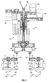
- FIG. 2 is an elevational sectional view as seen from direction 2--2 of FIG. 1 in accordance with the present invention.
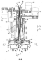
- FIG. 3 is an enlarged view of area 3 of FIG. 2 in accordance with the present invention.
- FIG. 4 is an enlarged view of area 4 of FIG. 3 in accordance with the present invention.
- pockets or poles 10 that need to be wound with coils may be presented to machine 11 by being located in carrying trays 12.
- pockets or poles 10 may be referred to interchangeably as pockets or poles.
- pockets or poles 10 will be referred to herein as "poles."
- Machine 11 may be provided with a rotating transfer table 13 capable of rotation around center 13' to transfer holding units 14 and 15 of the transfer table between stations 16 and 16'.
- the holding units may include holders 17, 18, and 19, each for holding a pole 10.
- the poles to be wound may be transferred from tray 12 to holders 17, 18, and 19 using, for example, a pick and place device capable of three orthogonal axis movements X, Y, and Z (into or out of the page of FIG. 1 ).
- holders 17, 18, and 19 may be provided with a clamping portion 20 for clamping the poles.
- the clamping portion is provided on the extremity of shaft 21, which is supported in bearings 22 of trolley structure 23.
- Motor belt unit 24, which is carried by trolley structure 23, is capable of rotating shaft 21 around axis R.
- Trolley structure 23 is capable of translating in directions H 1 (toward axis A 1 of FIG. 3 ) and H 2 (away from axis A 1 of FIG. 3 ) by means of guide 24' and a drive unit (not shown).
- winding unit 25 may include wire dispensers 26 and 27, each bolted to and supported by bracket plates 28 and 29. Each plate 28 and 29 may be bolted to a respective slide member 30 and 31. Slide members 30 and 31 are capable of translating backwards and forwards along respective radiuses R 2 and R 3 , which intersect the central axis A 1 of winding unit 25. Radiuses R 2 and R 3 may be parallel to directions H 1 and H 2 .
- Winding unit 25 may include casing structure 32 having guide portions (not shown) for constraining slide members 30 and 31 to translate backwards and forwards along respective radiuses R 2 and R 3 .
- Slide members 30 and 31 may receive and mesh with respective screw bars 33 and 34 so that rotations of the screw bars cause translation backwards and forwards along respective radiuses R 2 and R 3 .
- Screw bars 33 and 34 are supported in bearings 35 and 36, respectively, to accomplish the rotations.
- Pinion gears 37 and 38 of screw bars 33 and 34 may mesh with a common crown gear 39.
- Common crown gear 39 may be integral to the end of shaft 40.
- Shaft 40 may be supported in bearings of casing structure 32. Shaft 40 is received in tubular portion 32' of casing structure 32.
- first gear tube 43 and second gear tube 47 The opposite end portion 40' of shaft 40 is received in first gear tube 43 and second gear tube 47.
- First gear tube 43 may be supported by bearings 44 and 45, which are seated in a further casing structure 46. Further casing structure 46 corresponds to the frame of the machine.
- Second gear tube 47 may be supported by other bearings, which are also seated in further casing structure 46.
- Motor belt unit 49 is capable of rotating first gear tube 43
- motor belt unit 50 is capable of rotating second gear tube 47.
- Shaft 40 may be keyed on its outer surface to engage and slide in key ways of gear tube 47 in directions V 1 and V 2 .
- tubular portion 32' may be keyed on its outer surface to engage and slide in key ways of gear tube 43 in directions V 1 and V 2 .
- Shaft 40 may be hollow to allow wires W 1 and W 2 to run from a tensioner unit (not shown) to wire dispensers such as wire dispensers 26 and 27.
- Bushes 51 and 52 having flared surface portions may be assembled to the ends of shaft 40 to guarantee smooth running of wires W 1 and W 2 when entering and exiting shaft 40.
- Guide bars 53 of casing structure 32 may allow movement in directions V 1 and V 2 , parallel to axis A 1 .
- Guide bars 53 are constrained to move in directions V 1 and V 2 by being received in guide sleeves 58 of the frame of the machine.
- Shaft 40 will also move in directions V 1 and V 2 with casing structure 32.
- Joint member 54 may couple guide bars 53 to carriage member 55.
- Carriage member 55 may be translated in directions V 1 and V 2 by motor belt unit 56 and rotating screw arrangement 57, which is in meshing arrangement with carriage member 55.
- Guide sleeves 58 may be coupled to first gear tube 43 (e.g., using a force fit).
- Operations of the aforementioned winding unit may be as follows, as shown in FIG. 4 : prior to starting winding of wires W 1 and W 2 , the end portions of wires W 1 and W 2 may be anchored to anchoring posts 60 of pockets or poles 10 by lead pullers 59. Wires W 1 and W 2 may then be pulled around pockets or poles 10 by rotations around axis R on behalf of motor belt unit 24. At the same time, motor belt unit 50 may rotate shaft 40 so that the wire dispensers are translated backwards and forwards along respective radiuses R 2 and R 3 to stratify turns of wire W 1 and W 2 being wound on the pockets or poles by rotation around axis R.
- motor belt unit 56 may be rotated to move the wire dispensers in directions V 1 or V 2 to pass the wire turns W n from one layer to another on the pockets or poles. This stratification and layer formation of the wire turns W n around the pockets or poles is shown, for example, in FIG. 4 .
- motor unit 49 may cause rotations R o of casing structure 32 around axis A 1 in order to use rotation R o for indexing wire dispensers around axis A 1 , so that other pockets or poles (not shown) present on further holders (not shown) can be wound in the same way that has been described hereinabove.
- Translation of trolley structure 23 in direction H 2 may be used to create sufficient space between adjacent holders for their rotations around axis R and for the movements of the wire dispensers.
- Rotation R o translations V 1 and V 2 , and movements on radiuses R 2 and R 3 which move the wire dispensers with respect to the poles may be used by themselves or along with lead pull operations to route the ends of wires W 1 and W 2 in relation to the poles, as is required in termination operations.
- poles Once the poles have been wound and terminated in station 16', they may be returned to station 16 where they can be assembled together to form the wound stator core.
- wire coils may be wound on poles 10 by translating casing structure 32 in direction V 1 , rotating casing structure 32 in an initial direction R o around axis A 1 , translating casing structure 32 in direction V 2 , and rotating the casing structure in a direction opposite to the initial R o direction.
- Such movements brings wire dispensers 26 and 27 around respective poles 10 for one full turn of coil.
- wire dispensers 26 and 27 may be translated in directions R 2 and R 3 .
- holders 17 and 18 may be moved in direction H 2 such that poles 10 are spaced at a sufficient distance apart to allow for the wire coils to be wound on the poles.
- poles 10 Once poles 10 have been wound with the wire coils, poles 10 may be moved in direction H 1 to position the poles closer to one another for assembly of the dynamo-electric machine component.
Landscapes
- Engineering & Computer Science (AREA)
- Power Engineering (AREA)
- Manufacturing & Machinery (AREA)
- Manufacture Of Motors, Generators (AREA)
- Discharge Heating (AREA)
- Windings For Motors And Generators (AREA)
Claims (23)
- Vorrichtung (11) zum Wickeln von Drahtspulen auf eine Vielzahl von Pole (10) und zum Zusammenbau der Vielzahl von Pole, zum Bilden eines dynamoelektrischen Maschinenbauteils, umfassend: Eine Vielzahl von Halteelementen (17, 18, 19), von denen jedes jeweils einen Pol aus der Vielzahl der Pole (10) hält, während die Drahtspulen gewickelt werden, wobei jedes Halteelement aus der Vielzahl der Halteelemente ausgebildet ist, um seinen jeweiligen Pol um eine Mittenachse (R) des Halteelements zu drehen; eine Vielzahl von Drahtabgabeelementen (26, 27) von denen jedes Draht (W1, W2) auf einen jeweiligen Pol aus der Vielzahl der Pole (10) abgibt, wobei der Draht auf jeden Pol abgegeben wird während jeder Pol um die Mittenachse (R) seines jeweiligen Halteelements (17, 18, 19) rotiert; und eine Stützstruktur (32), die ausgebildet ist zum Stützen der Vielzahl der Drahtabgabeelemente (26, 27), wobei der Draht auf jeden Pol geschichtet wird, durch die simultane radiale Bewegung der Vielzahl der Drahtabgabeelemente (26, 27) bezüglich einer Mittenachse (A1) der Stützstruktur (32).
- Die Vorrichtung gemäß Anspruch 1, wobei jedes der Halteelementen (17, 18, 19) weiterhin ausgebildet ist, um seinen jeweiligen Pol (10) hin zur und weg von der Mittenachse (A1) der Stützstruktur (32) zu verschieben.
- Die Vorrichtung gemäß Anspruch 2, wobei die translatorische Bewegung eines jeden Pols (10), parallel zu der radialen Bewegung seines jeweiligen Drahtabgabeelements (26, 27) ist.
- Die Vorrichtung gemäß Anspruch 1, weiterhin umfassend: Ein Schaftelement (40), dass durch die Stützstruktur (32) gestützt wird und das um die Mittenachse (A1) der Stützstruktur angeordnet ist, wobei eine Rotation des Schaftelements (40) um die Mittenachse der Stützstruktur die simultane Radialbewegung der Vielzahl der Drahtabgabeelemente (26, 27) bereitstellt.
- Die Vorrichtung gemäß Anspruch 4, wobei das Schaftelement (40) mit einem Hülsenelement (47) verzahnt ist, sodass eine Rotation des Hülsenelements auf das Schaftelement weitergegeben wird.
- Die Vorrichtung gemäß Anspruch 1, weiterhin umfassend: Einen Transfertisch (13), der ausgebildet ist, um die Vielzahl von Halteelementen (17, 18, 19) zu stützen und zum rotieren des Transfertischs (13) um das Zentrum (13), sodass die Vielzahl von Halteelementen (17, 18, 19) von einer Position zum Wickeln der Drahtspulen zu einer Position zum Bilden des dynamoelektrischen Maschinenbauteils verlagert werden.
- Die Vorrichtung gemäß Anspruch 1, weiterhin umfassend: Eine Rohrstruktur (32'), die durch die Stützstruktur gestützt wird und entlang der Mittenachse (A1) der Stützstruktur angeordnet ist, wobei eine Rotation der Rohrstruktur um die Mittenachse der Stützstruktur die Gesamtheit der Stützstruktur (32) um die Mittenachse (A1) der Stützstruktur (32) rotiert.
- Die Vorrichtung gemäß Anspruch 7, wobei die Rohrstruktur (32') mit einem Hülsenelement (43) verzahnt ist, sodass die Rotation des Hülsenelements (43) auf die Rohrstruktur (32') weitergegeben wird.
- Die Vorrichtung gemäß Anspruch 1, weiterhin umfassend: Ein Führungsgestänge (53), das durch die Stützstruktur (32) gestützt wird, das ausgebildet ist, um die Gesamtheit der Stützstruktur (32) entlang der Mittenachse (A1) der Stützstruktur (32) zu verschieben.
- Die Vorrichtung gemäß Anspruch 9, wobei das Führungsgestänge (53) mit einem Transportelement (55) gekoppelt ist, sodass eine translatorische Bewegung des Transportelements (55) an das Führungsgestänge (53) weitergegeben wird,
- Die Vorrichtung gemäß Anspruch 1, wobei ein Ende des Drahtes, der auf einen Pol (10) gewickelt wurde, zum Abschluss geführt wird durch die radiale Bewegung der Vielzahl der Drahtabgabeelemente (26, 27) bezüglich der Mittenachse (A1) der Stützstruktur (32), eine Rotation der Gesamtheit der Stützstruktur (32) um die Mittenachse der Stützstruktur oder eine Verschiebung der Gesamtheit der Stützstruktur (32) entlang der Mittenachse (A1) der Stützstruktur (32).
- Die Vorrichtung gemäß Anspruch 1, weiterhin umfassend: eine Rohrstruktur (32'), die durch die Stützstruktur (32) gestützt wird und entlang der Mittenachse (A1) der Stützstruktur (32) angeordnet ist, wobei eine Rotation der Rohrstruktur (32') um die Mittenachse (A1) der Stützstruktur (32) die Gesamtheit der Stützstruktur (32) um die Mittenachse der Stützstruktur dreht; ein Führungsgestänge (53), das durch die Stützstruktur gestützt wird und das ausgebildet ist, um die Gesamtheit der Stützstruktur entlang der Mittenachse (A1) der Stützstruktur (32) zu verschieben; und wobei ein Ende eines Drahtes, der auf einen Pol (10) gewickelt wurde zum Abschluss geführt wird durch die Radialbewegung der Vielzahl der Drahtabgabeelemente (26, 27) bezüglich der Mittenachse der Stützstruktur, die Rotation der Gesamtheit der Stützstruktur (32) um die Mittenachse (A1) der Stützstruktur oder die Verschiebung der Gesamtheit der Stützstruktur entlang der Mittenachse der Stützstruktur.
- Ein Verfahren zum Wickeln von Drahtspulen auf eine Vielzahl von Pole (10) und zum Zusammenbau der Vielzahl der Pole, um ein dynamoelektrisches Maschinenbauteil zu bilden, umfassend: Bereitstellen einer Vorrichtung (11) zum Wickeln von Drahtspulen, umfassend eine Vielzahl von Halteelementen (17, 18, 19), von denen jedes jeweils einen Pol aus der Vielzahl der Pole hält, während die Drahtspulen gewickelt werden, eine Vielzahl von Drahtabgabeelementen (26, 27), von denen jedes Draht auf einen jeweiligen Pol aus der Vielzahl der Pole (10) abgibt und eine Stützstruktur (32), die ausgebildet ist, um die Vielzahl der Drahtabgabeelemente (26, 27) zu stützen; Rotieren jedes Pols aus der Vielzahl der Pole um eine Mittelachse (R) des jeweiligen Halteelements mit seinem jeweiligen Halteelement (17, 18, 19), sodass der Draht auf jeden Pol (10) abgegeben wird; und simultanes Bewegen der Vielzahl der Drahtabgabeelemente radial bezüglich einer Mittenachse (A1) der Stützstruktur (32), sodass der Draht auf jeden Pol (10) geschichtet wird.
- Das Verfahren gemäß Anspruch 13, weiterhin umfassend: Verschieben jedes der Pole (10) hin zu und weg von der Mittenachse (A1) der Stützstruktur (32), mit dessen jeweiligen Haltelement (17, 18, 19).
- Das Verfahren gemäß Anspruch 14, wobei die translatorische Bewegung jedes Pols (10) parallel zu der radialen Bewegung von dessen jeweiligen Drahtabgabeelement (26, 27) ist.
- Das Verfahren gemäß Anspruch 13, wobei die Vorrichtung weiterhin ein Schaftelement (40) umfasst, das durch die Stützstruktur (32) gestützt wird und um die Mittenachse (A1) der Stützstruktur (32) angeordnet ist und wobei simultanes bewegen der Vielzahl der Drahtabgabeelemente (26, 27) radial bezüglich einer Mittenachse (A1) der Stützstruktur eine Rotation des Schaftelements (40) um die Mittelachse der Stützstruktur umfasst, um die simultane Radialbewegung bereitzustellen.
- Das Verfahren gemäß Anspruch 13, wobei die Vorrichtung weiterhin eine Rohrstruktur (32') umfasst, die durch die Stützstruktur (32) gestützt wird und entlang der Mittenachse (A1) der Stützstruktur angeordnet ist, wobei das Verfahren weiterhin umfasst: Rotieren der Gesamtheit der Stützstruktur (32) um die Mittenachse (A1) der Stützstruktur (32) durch rotieren der Rohrstrüktur (32) um die Mittenachse der Stützstruktur.
- Das Verfahren gemäß Anspruch 13, wobei die Vorrichtung weiterhin ein Führungsgestänge (53) umfasst, das durch die Stützstruktur (32) gestützt wird, wobei das Verfahren weiterhin umfasst: Verschieben der Gesamtheit der Stützstruktur (32) entlang der Mittenachse (A1) der Stützstruktur mit dem Führungsgestänge (53).
- Das Verfahren gemäß Anspruch 13, wobei das Verfahren weiterhin umfasst: Führen eines Endes des Drahtes, der um einen Pol (10) gewickelt wurde zum Abschluss durch radiales bewegen der Vielzahl der Drahtabgabeelemente (26, 27) bezüglich der Mittenachse (A1) der Stützstruktur (32), rotieren der Gesamtheit der Stützstruktur um die Mittenachse der Stützstruktur oder verschieben der Gesamtheit der Stützstruktur entlang der Mittenachse der Stützstruktur.
- Vorrichtung (11) zum Wickeln von Drahtspulen auf eine Vielzahl von Pole (10) und zum Zusammenbau der Vielzahl der Pole, um ein dynamoelektrisches Maschinenbauteil zu bilden, umfassend: Eine Vielzahl von Halteelementen (17, 18, 19), von denen jedes einen jeweiligen Pol aus der Vielzahl der Pole (10) hält, während die Drahtspulen gewickelt werden, wobei jedes Halteelement aus der Vielzahl der Halteelemente an einer ersten jeweiligen Position während die Drahtspulen gewickelt werden angeordnet ist; eine Vielzahl von Drahtabgabeelementen (26, 27), von denen jedes Draht auf einen jeweiligen Pol aus der Vielzahl der Pole (10) abgibt und eine Stützstruktur (32), die ausgebildet ist, um die Vielzahl der Drahtabgabeelemente zu stützen, wobei der Draht (W1, W2), auf jeden Pol (10) abgegeben wird, um die Drahtspulen durch Bewegung der Gesamtheit der Stützstruktur (32) zu wickeln und wobei die Vielzahl der Pole (10) zusammen gesetzt werden, um das dynamoelektrische Maschinenbauteil zu bilden, nachdem die Drahtspulen gewickelt wurden, durch Bewegung jedes Halteelements (17,18,19) aus der Vielzahl der Halteelemente zu einer zweiten jeweiligen Position.
- Die Vorrichtung gemäß Anspruch 20, wobei der Draht (W1, W2) auf jeden der Pole, durch simultane radiale Bewegung der Vielzahl der Drahtabgabeelemente (26, 27) bezüglich einer Mittenachse (A1) der Stützstruktur (32) geschichtet wird.
- Ein Verfahren zum Wickeln von Drahtspulen auf eine Vielzahl von Pole (10) und zum Zusammenbau der Vielzahl der Pole (10), um ein dynamoelektrisches Maschinenbauteil zu bilden, umfassend: Bereitstellen einer Vorrichtung (11) zum Wickeln der Drahtspulen, umfassend eine Vielzahl von Halteelementen (17, 18, 19), von denen jedes einen jeweiligen Pol aus der Vielzahl der Pole (10) hält, während die Drahtspulen gewickelt werden, eine Vielzahl von Drahtabgabeelementen (26, 27), von denen jeder Draht auf einen jeweiligen Pol aus der Vielzahl der Pole (10) abgibt und eine Stützstruktur (32), die ausgebildet ist, um die Vielzahl der Drahtabgabeelemente (26, 27) zu stützen; Anordnen eines jeden Halteelements aus der Vielzahl der Halteelemente (17, 18, 19) an einer ersten jeweiligen Position, um die Drahtspulen zu wickeln; Bewegen der Gesamtheit der Stützstruktur (32), sodass der Draht (W1, W2) auf jeden Pol (10) abgegeben wird, um die Drahtspulen zu wickeln; und nachdem die Drahtspulen gewickelt wurden, Bewegen eines jeden Halteelements aus der Vielzahl der Halteelemente (17, 18, 19) zu einer jeweiligen zweiten Position, um die Vielzahl der Pole (10) zusammenzubauen, um das dynamoelektrische Maschinenbauteil zu bilden.
- Das Verfahren gemäß Anspruch 22, weiterhin umfassend: Simultanes bewegen der Vielzahl der Drahtabgabeelemente (26, 27) radial bezüglich zu einer Mittenachse (A1) der Stützstruktur (32), sodass der Draht auf jeden Pol (10), während der Wicklung der Drahtspulen, geschichtet wird.
Priority Applications (1)
| Application Number | Priority Date | Filing Date | Title |
|---|---|---|---|
| SI200431167T SI1629588T1 (sl) | 2003-05-22 | 2004-05-21 | Aparat in postopek za navijanje žičnih tuljav za komponente dinamo-električnih strojev |
Applications Claiming Priority (2)
| Application Number | Priority Date | Filing Date | Title |
|---|---|---|---|
| US47286203P | 2003-05-22 | 2003-05-22 | |
| PCT/EP2004/005477 WO2004105218A1 (en) | 2003-05-22 | 2004-05-21 | Apparatus and method for winding wire coils for dynamo-electric machine components |
Publications (2)
| Publication Number | Publication Date |
|---|---|
| EP1629588A1 EP1629588A1 (de) | 2006-03-01 |
| EP1629588B1 true EP1629588B1 (de) | 2009-04-08 |
Family
ID=33476982
Family Applications (1)
| Application Number | Title | Priority Date | Filing Date |
|---|---|---|---|
| EP04734227A Expired - Lifetime EP1629588B1 (de) | 2003-05-22 | 2004-05-21 | Vorrichtung und verfahren zum wickeln von spulen für komponenten dynamoelektrischer maschinen |
Country Status (7)
| Country | Link |
|---|---|
| US (1) | US7243874B2 (de) |
| EP (1) | EP1629588B1 (de) |
| AT (1) | ATE428212T1 (de) |
| DE (1) | DE602004020462D1 (de) |
| DK (1) | DK1629588T3 (de) |
| SI (1) | SI1629588T1 (de) |
| WO (1) | WO2004105218A1 (de) |
Families Citing this family (7)
| Publication number | Priority date | Publication date | Assignee | Title |
|---|---|---|---|---|
| ITAL20090001A1 (it) * | 2009-02-17 | 2010-08-17 | Cravanzola E Veglio S N C | Apparecchiatura per la realizzazione di bonine eletriche e simili |
| IT1394587B1 (it) | 2009-04-29 | 2012-07-05 | Atop Spa | Apparecchiatura e metodo per avvolgere e terminare nuclei per macchine dinamo elettriche |
| ITPI20130020A1 (it) * | 2013-03-20 | 2014-09-21 | Atop Spa | Apparecchiatura e metodo per produrre statori di macchine dinamoelettriche formati da un assemblato di segmenti di polo |
| JP5942236B1 (ja) * | 2015-07-06 | 2016-06-29 | 福井県 | コイルユニット配列装置 |
| US9991050B2 (en) * | 2016-03-08 | 2018-06-05 | Ming-Chang Lee | Wire winding device for stator |
| EP4012903A1 (de) | 2020-12-09 | 2022-06-15 | ATOP S.p.A. | Verfahren und vorrichtung zur herstellung eines stators einer dynamoelektrischen maschine |
| CN116526780B (zh) * | 2023-05-17 | 2024-03-08 | 跃科智能制造(无锡)有限公司 | 一种卷绕效果好的扁铜线定子卷线设备 |
Family Cites Families (17)
| Publication number | Priority date | Publication date | Assignee | Title |
|---|---|---|---|---|
| US3228616A (en) * | 1962-12-26 | 1966-01-11 | United Aircraft Corp | Apparatus for changing a helical winding angle |
| US3397850A (en) * | 1966-10-31 | 1968-08-20 | Engineering Technology Inc | Filament winding apparatus |
| US3433434A (en) * | 1967-01-26 | 1969-03-18 | Philip D Rosengarten | Filament winding machine |
| US3989200A (en) * | 1975-04-22 | 1976-11-02 | Bachi, Inc. | Non-circular perfect layer electrical coils |
| US4078735A (en) * | 1976-01-06 | 1978-03-14 | The Entwistle Company | Multicoil traverse winder |
| DE69214060D1 (de) * | 1991-07-30 | 1996-10-31 | Axis Spa | Programmierbar gesteuerte Wickelverfahren für Unterteile elektrischer Motoren und Vorrichtung |
| US5413289A (en) * | 1991-07-30 | 1995-05-09 | Axis Usa, Inc. | Programmably controlled armature winding apparatus |
| US5511733A (en) * | 1994-02-23 | 1996-04-30 | Northrop Grumman Corporation | Negative radius coil winders |
| US5681006A (en) * | 1996-01-22 | 1997-10-28 | General Electric Company | Apparatus for winding an electrical conductor on a coil form |
| JPH10233331A (ja) * | 1997-02-19 | 1998-09-02 | Toyo Denso Co Ltd | 点火コイルのバンク巻方法 |
| ES2193426T3 (es) * | 1997-02-19 | 2003-11-01 | Toyo Denso Kk | Metodo de arrollar por bancos una bobina de encendido. |
| US6533208B1 (en) * | 1999-08-12 | 2003-03-18 | Axis U.S.A., Inc. | Winding cores with stratification motion |
| US6532645B1 (en) * | 1999-11-03 | 2003-03-18 | Axis Usa, Inc. | Wire winding apparatus for dynamo-electric components |
| US6622955B2 (en) * | 2000-09-22 | 2003-09-23 | Axis Usa, Inc. | Winder, and methods for stratified winding, of wire onto a dynamo-electric core |
| EP1283585A1 (de) * | 2001-08-06 | 2003-02-12 | ATS Wickel- und Montagetechnik AG | Vorrichtung zum Wickeln eines mehrpoligen Stators |
| JP3666748B2 (ja) * | 2002-05-10 | 2005-06-29 | 株式会社デンソー | 巻線装置および巻線方法 |
| US20040046476A1 (en) * | 2002-05-14 | 2004-03-11 | Raffaele Becherucci | Dynamo-electric machine component winding methods and apparatus |
-
2004
- 2004-05-20 US US10/851,721 patent/US7243874B2/en not_active Expired - Lifetime
- 2004-05-21 EP EP04734227A patent/EP1629588B1/de not_active Expired - Lifetime
- 2004-05-21 SI SI200431167T patent/SI1629588T1/sl unknown
- 2004-05-21 AT AT04734227T patent/ATE428212T1/de not_active IP Right Cessation
- 2004-05-21 WO PCT/EP2004/005477 patent/WO2004105218A1/en not_active Ceased
- 2004-05-21 DK DK04734227T patent/DK1629588T3/da active
- 2004-05-21 DE DE602004020462T patent/DE602004020462D1/de not_active Expired - Lifetime
Also Published As
| Publication number | Publication date |
|---|---|
| DE602004020462D1 (de) | 2009-05-20 |
| SI1629588T1 (sl) | 2009-12-31 |
| EP1629588A1 (de) | 2006-03-01 |
| WO2004105218A1 (en) | 2004-12-02 |
| ATE428212T1 (de) | 2009-04-15 |
| US7243874B2 (en) | 2007-07-17 |
| DK1629588T3 (da) | 2009-08-17 |
| US20050006519A1 (en) | 2005-01-13 |
Similar Documents
| Publication | Publication Date | Title |
|---|---|---|
| US8490280B2 (en) | Winding device | |
| EP2173020B1 (de) | Wickelkerne mit Stratifizierungsbewegung | |
| US7498709B2 (en) | Method and apparatus for winding segments of a segmented wound member of an electromechanical device | |
| US8482180B2 (en) | Stator, brushless motor, and manufacturing method of the same | |
| CN101401283B (zh) | 用于缠绕电动/发电机芯部的线圈的设备和方法 | |
| EP1098425B1 (de) | Wickelmaschine für Komponenten einer dynamo-elektrischen Maschine und entsprechendes Herstellungsverfahren | |
| CN102104301A (zh) | 线圈的制造装置 | |
| JP2004032886A (ja) | 回転電機のセグメント順次接合ステータコイルおよびその製造方法 | |
| CN103904844A (zh) | 用于缠绕和终止发电机芯部的设备 | |
| US7243874B2 (en) | Apparatus and methods for winding wire coils for dynamo-electric machine components | |
| KR101346715B1 (ko) | 다이나모 전기 기계 코어 내의 복수개의 와이어의 리드를 종결시키기 위한 방법 및 장치 | |
| EP3322072B1 (de) | Spuleneinheitsanordnungsvorrichtung | |
| JP2005102402A (ja) | ステータ製造装置 | |
| KR101112708B1 (ko) | 스테이터의 조립방법 및 그 조립장치 | |
| JP2016063663A (ja) | 固定子の製造方法および装置 | |
| KR20130132445A (ko) | 다이나모일렉트릭 장치의 코어 부품의 코일을 권취하기 위하여 사용된 와이어 분배 부재의 운동을 위한 장치 | |
| JP7330334B1 (ja) | 巻線装置および固定子製造方法 | |
| JP2006054967A (ja) | コイル巻線方法 | |
| US7847464B2 (en) | Armature of rotary electric machine and method for producing same | |
| JP2012257385A (ja) | コイル導線の巻取方法及び巻取装置 |
Legal Events
| Date | Code | Title | Description |
|---|---|---|---|
| PUAI | Public reference made under article 153(3) epc to a published international application that has entered the european phase |
Free format text: ORIGINAL CODE: 0009012 |
|
| 17P | Request for examination filed |
Effective date: 20051221 |
|
| AK | Designated contracting states |
Kind code of ref document: A1 Designated state(s): AT BE BG CH CY CZ DE DK EE ES FI FR GB GR HU IE IT LI LU MC NL PL PT RO SE SI SK TR |
|
| DAX | Request for extension of the european patent (deleted) | ||
| RAP1 | Party data changed (applicant data changed or rights of an application transferred) |
Owner name: AXIS USA INC. Owner name: ATOP S.P.A. |
|
| 17Q | First examination report despatched |
Effective date: 20080407 |
|
| GRAP | Despatch of communication of intention to grant a patent |
Free format text: ORIGINAL CODE: EPIDOSNIGR1 |
|
| RAP1 | Party data changed (applicant data changed or rights of an application transferred) |
Owner name: ATOP S.P.A. |
|
| GRAS | Grant fee paid |
Free format text: ORIGINAL CODE: EPIDOSNIGR3 |
|
| GRAA | (expected) grant |
Free format text: ORIGINAL CODE: 0009210 |
|
| AK | Designated contracting states |
Kind code of ref document: B1 Designated state(s): AT BE BG CH CY CZ DE DK EE ES FI FR GB GR HU IE IT LI LU MC NL PL PT RO SE SI SK TR |
|
| REG | Reference to a national code |
Ref country code: GB Ref legal event code: FG4D |
|
| REG | Reference to a national code |
Ref country code: CH Ref legal event code: EP |
|
| REG | Reference to a national code |
Ref country code: IE Ref legal event code: FG4D |
|
| REF | Corresponds to: |
Ref document number: 602004020462 Country of ref document: DE Date of ref document: 20090520 Kind code of ref document: P |
|
| REG | Reference to a national code |
Ref country code: CH Ref legal event code: NV Representative=s name: HEPP WENGER RYFFEL AG |
|
| REG | Reference to a national code |
Ref country code: DK Ref legal event code: T3 |
|
| NLV1 | Nl: lapsed or annulled due to failure to fulfill the requirements of art. 29p and 29m of the patents act | ||
| PG25 | Lapsed in a contracting state [announced via postgrant information from national office to epo] |
Ref country code: ES Free format text: LAPSE BECAUSE OF FAILURE TO SUBMIT A TRANSLATION OF THE DESCRIPTION OR TO PAY THE FEE WITHIN THE PRESCRIBED TIME-LIMIT Effective date: 20090719 Ref country code: AT Free format text: LAPSE BECAUSE OF FAILURE TO SUBMIT A TRANSLATION OF THE DESCRIPTION OR TO PAY THE FEE WITHIN THE PRESCRIBED TIME-LIMIT Effective date: 20090408 Ref country code: PT Free format text: LAPSE BECAUSE OF FAILURE TO SUBMIT A TRANSLATION OF THE DESCRIPTION OR TO PAY THE FEE WITHIN THE PRESCRIBED TIME-LIMIT Effective date: 20090908 Ref country code: FI Free format text: LAPSE BECAUSE OF FAILURE TO SUBMIT A TRANSLATION OF THE DESCRIPTION OR TO PAY THE FEE WITHIN THE PRESCRIBED TIME-LIMIT Effective date: 20090408 |
|
| PG25 | Lapsed in a contracting state [announced via postgrant information from national office to epo] |
Ref country code: NL Free format text: LAPSE BECAUSE OF FAILURE TO SUBMIT A TRANSLATION OF THE DESCRIPTION OR TO PAY THE FEE WITHIN THE PRESCRIBED TIME-LIMIT Effective date: 20090408 Ref country code: SE Free format text: LAPSE BECAUSE OF FAILURE TO SUBMIT A TRANSLATION OF THE DESCRIPTION OR TO PAY THE FEE WITHIN THE PRESCRIBED TIME-LIMIT Effective date: 20090708 Ref country code: PL Free format text: LAPSE BECAUSE OF FAILURE TO SUBMIT A TRANSLATION OF THE DESCRIPTION OR TO PAY THE FEE WITHIN THE PRESCRIBED TIME-LIMIT Effective date: 20090408 |
|
| PG25 | Lapsed in a contracting state [announced via postgrant information from national office to epo] |
Ref country code: MC Free format text: LAPSE BECAUSE OF NON-PAYMENT OF DUE FEES Effective date: 20090531 |
|
| PG25 | Lapsed in a contracting state [announced via postgrant information from national office to epo] |
Ref country code: CZ Free format text: LAPSE BECAUSE OF FAILURE TO SUBMIT A TRANSLATION OF THE DESCRIPTION OR TO PAY THE FEE WITHIN THE PRESCRIBED TIME-LIMIT Effective date: 20090408 Ref country code: RO Free format text: LAPSE BECAUSE OF FAILURE TO SUBMIT A TRANSLATION OF THE DESCRIPTION OR TO PAY THE FEE WITHIN THE PRESCRIBED TIME-LIMIT Effective date: 20090408 Ref country code: EE Free format text: LAPSE BECAUSE OF FAILURE TO SUBMIT A TRANSLATION OF THE DESCRIPTION OR TO PAY THE FEE WITHIN THE PRESCRIBED TIME-LIMIT Effective date: 20090408 |
|
| PLBE | No opposition filed within time limit |
Free format text: ORIGINAL CODE: 0009261 |
|
| STAA | Information on the status of an ep patent application or granted ep patent |
Free format text: STATUS: NO OPPOSITION FILED WITHIN TIME LIMIT |
|
| PG25 | Lapsed in a contracting state [announced via postgrant information from national office to epo] |
Ref country code: SK Free format text: LAPSE BECAUSE OF FAILURE TO SUBMIT A TRANSLATION OF THE DESCRIPTION OR TO PAY THE FEE WITHIN THE PRESCRIBED TIME-LIMIT Effective date: 20090408 Ref country code: BE Free format text: LAPSE BECAUSE OF FAILURE TO SUBMIT A TRANSLATION OF THE DESCRIPTION OR TO PAY THE FEE WITHIN THE PRESCRIBED TIME-LIMIT Effective date: 20090408 |
|
| REG | Reference to a national code |
Ref country code: IE Ref legal event code: MM4A |
|
| 26N | No opposition filed |
Effective date: 20100111 |
|
| GBPC | Gb: european patent ceased through non-payment of renewal fee |
Effective date: 20090708 |
|
| PG25 | Lapsed in a contracting state [announced via postgrant information from national office to epo] |
Ref country code: BG Free format text: LAPSE BECAUSE OF FAILURE TO SUBMIT A TRANSLATION OF THE DESCRIPTION OR TO PAY THE FEE WITHIN THE PRESCRIBED TIME-LIMIT Effective date: 20090708 |
|
| PG25 | Lapsed in a contracting state [announced via postgrant information from national office to epo] |
Ref country code: IE Free format text: LAPSE BECAUSE OF NON-PAYMENT OF DUE FEES Effective date: 20090521 |
|
| PG25 | Lapsed in a contracting state [announced via postgrant information from national office to epo] |
Ref country code: GB Free format text: LAPSE BECAUSE OF NON-PAYMENT OF DUE FEES Effective date: 20090708 |
|
| PG25 | Lapsed in a contracting state [announced via postgrant information from national office to epo] |
Ref country code: GR Free format text: LAPSE BECAUSE OF FAILURE TO SUBMIT A TRANSLATION OF THE DESCRIPTION OR TO PAY THE FEE WITHIN THE PRESCRIBED TIME-LIMIT Effective date: 20090709 |
|
| PG25 | Lapsed in a contracting state [announced via postgrant information from national office to epo] |
Ref country code: IT Free format text: LAPSE BECAUSE OF NON-PAYMENT OF DUE FEES Effective date: 20090521 |
|
| PG25 | Lapsed in a contracting state [announced via postgrant information from national office to epo] |
Ref country code: LU Free format text: LAPSE BECAUSE OF NON-PAYMENT OF DUE FEES Effective date: 20090521 |
|
| PG25 | Lapsed in a contracting state [announced via postgrant information from national office to epo] |
Ref country code: HU Free format text: LAPSE BECAUSE OF FAILURE TO SUBMIT A TRANSLATION OF THE DESCRIPTION OR TO PAY THE FEE WITHIN THE PRESCRIBED TIME-LIMIT Effective date: 20091009 |
|
| PGRI | Patent reinstated in contracting state [announced from national office to epo] |
Ref country code: IT Effective date: 20110616 |
|
| PG25 | Lapsed in a contracting state [announced via postgrant information from national office to epo] |
Ref country code: TR Free format text: LAPSE BECAUSE OF FAILURE TO SUBMIT A TRANSLATION OF THE DESCRIPTION OR TO PAY THE FEE WITHIN THE PRESCRIBED TIME-LIMIT Effective date: 20090408 |
|
| PG25 | Lapsed in a contracting state [announced via postgrant information from national office to epo] |
Ref country code: CY Free format text: LAPSE BECAUSE OF FAILURE TO SUBMIT A TRANSLATION OF THE DESCRIPTION OR TO PAY THE FEE WITHIN THE PRESCRIBED TIME-LIMIT Effective date: 20090408 |
|
| REG | Reference to a national code |
Ref country code: FR Ref legal event code: PLFP Year of fee payment: 13 |
|
| REG | Reference to a national code |
Ref country code: FR Ref legal event code: PLFP Year of fee payment: 14 |
|
| REG | Reference to a national code |
Ref country code: FR Ref legal event code: PLFP Year of fee payment: 15 |
|
| P01 | Opt-out of the competence of the unified patent court (upc) registered |
Effective date: 20230508 |
|
| PGFP | Annual fee paid to national office [announced via postgrant information from national office to epo] |
Ref country code: IT Payment date: 20230525 Year of fee payment: 20 Ref country code: FR Payment date: 20230523 Year of fee payment: 20 Ref country code: DK Payment date: 20230524 Year of fee payment: 20 Ref country code: DE Payment date: 20230530 Year of fee payment: 20 Ref country code: CH Payment date: 20230602 Year of fee payment: 20 |
|
| PGFP | Annual fee paid to national office [announced via postgrant information from national office to epo] |
Ref country code: SI Payment date: 20230503 Year of fee payment: 20 |
|
| REG | Reference to a national code |
Ref country code: DE Ref legal event code: R071 Ref document number: 602004020462 Country of ref document: DE |
|
| REG | Reference to a national code |
Ref country code: DK Ref legal event code: EUP Expiry date: 20240521 |
|
| REG | Reference to a national code |
Ref country code: CH Ref legal event code: PL |
|
| PG25 | Lapsed in a contracting state [announced via postgrant information from national office to epo] |
Ref country code: SI Free format text: LAPSE BECAUSE OF EXPIRATION OF PROTECTION Effective date: 20240522 |