EP1629366B1 - Systeme a camera unique permettant d'effectuer une entree a base de gestes et d'indiquer une cible - Google Patents
Systeme a camera unique permettant d'effectuer une entree a base de gestes et d'indiquer une cible Download PDFInfo
- Publication number
- EP1629366B1 EP1629366B1 EP01273319A EP01273319A EP1629366B1 EP 1629366 B1 EP1629366 B1 EP 1629366B1 EP 01273319 A EP01273319 A EP 01273319A EP 01273319 A EP01273319 A EP 01273319A EP 1629366 B1 EP1629366 B1 EP 1629366B1
- Authority
- EP
- European Patent Office
- Prior art keywords
- image
- display screen
- coordinates
- preliminary
- setup
- Prior art date
- Legal status (The legal status is an assumption and is not a legal conclusion. Google has not performed a legal analysis and makes no representation as to the accuracy of the status listed.)
- Expired - Lifetime
Links
Images


Classifications
-
- G—PHYSICS
- G06—COMPUTING; CALCULATING OR COUNTING
- G06F—ELECTRIC DIGITAL DATA PROCESSING
- G06F3/00—Input arrangements for transferring data to be processed into a form capable of being handled by the computer; Output arrangements for transferring data from processing unit to output unit, e.g. interface arrangements
- G06F3/01—Input arrangements or combined input and output arrangements for interaction between user and computer
- G06F3/03—Arrangements for converting the position or the displacement of a member into a coded form
- G06F3/0304—Detection arrangements using opto-electronic means
Definitions
- the invention relates to systems and methods for inputting information about the position of a target and more particularly to such systems that employ a single camera image.
- Many computer-based systems require information about the location of a target.
- the familiar mouse is used to select a control or a coordinate on a screen.
- Another area in which target location data are input to a computer is in the field of automated video-conferencing systems.
- a user may aim a camera at an object of interest by simply indicating the object, or by controlling it with a joystick.
- Work is proceeding on many fronts on systems that allow users to indicate targets without the use of a mouse or a joystick, but by using the familiar gestures normally used to indicate targets to other people.
- gesture-based systems are more intuitive and easier to control than conventional systems that require explicit commands such as voice-command ("command-control,” basically a speech-based symbol processor where each verbal command corresponds to an instruction, for example "PAN - LEFT,” “UP,” DOWN''' etc.), joystick control.
- command-control basically a speech-based symbol processor where each verbal command corresponds to an instruction, for example "PAN - LEFT,” “UP,” DOWN''' etc.), joystick control.
- a camera-based system is described in detail in the article '''Finger-Pointer': Pointing interface by Image Processing" by Masaaki Fukumoto, Yasuhito Suenga and Kenji Mase.
- Such systems are often complex because the multiple angle views may need to be combined to generate a three-dimensional model of the actual scene in order to determine the three-dimensional vector that coincides with the user's indication.
- the cameras need to be positioned and aimed and their positions and orientations precisely defined. The three-dimensional model is then used to determine the target to which the user is pointing.
- the mouse indicates the position of a desired two-dimensional coordinate on a screen by indicating relative positions.
- the starting position of the location indicated by it is arbitrary. Only by using feedback and relative movements can a user ultimately indicate a target position.
- a simple single-camera gesture-based technique which works much like a mouse, is described in US Patent No. 5,594,469 .
- the user's gestures are acquired by a single camera and a position indicated by feedback.
- the user modifies the gesture until the feedback signal indicates the desired result. For example, the user moves his/her hand and the direction and magnitude of displacement are mapped to relative direction and magnitude displacements of a cursor on a screen.
- This system suffers from the same drawback as a mouse or joystick in that the starting position is arbitrary and (usually visual) feedback is required.
- the position of a target lying on a plane is indicated by inputting the projection of a pointing direction onto the plane. If the target is known to lie on a contour in the plane, the position is specified unambiguously by the direction projection, the intersection of the contour and the projection being the desired target.
- the two-dimensional position of a target can be specified by inputting its axial coordinates in successive steps.
- the image containing the target is translated and/or rotated and the target indicated again. The intersection of the two direction projections is then used to determine the position of the target in 2-space.
- the direction indications may be input by a camera or other method, such as one or more radio transmitters, casting of a shadow, etc.
- the strategy is to use planar projection transforms in the manner disclosed in WO 01/88681 A1 , reference above, but instead of using two cameras to provide independent planar projections of a single direction-indicating vector onto a common plane, coordinates of a single camera's image are mapped to a known plane providing only one dimension of coordinate information rather than two.
- This single dimension can be used in multiple ways. For example, a single-axis control such as a slider control could be controlled with pointing gestures. A point on a road shown on a road map may also be indicated. Also, by using successive gesture inputs, say one for the row and one for the column of a table, a desired cell can be indicated.
- an image of a scene can be projected onto a screen and a target indicated on the scene. Then, after the first indication, the scene may be translated and/or rotated and the target pointed out again. From the two planar projections of these two pointing indications, the target's location may be deduced by simply finding the intersection of the two projections.
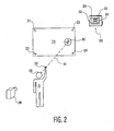
- a camera 150 is supported on a platform 110 behind a screen 135 with an aperture 155.
- the camera 150 is aimable at a scene in front of the screen such that the camera 150 views the scene through the aperture 155.
- the camera's 150 aim is such that the edges 170 of the aperture 155 are visible in its image.
- the field of view of the camera 150 is slightly clipped by the aperture 155.
- the purpose of the screen 135 is to present four markers in the form of the corners 261- 264 of the aperture 155 and any apparatus that would be effective for that purpose would suffice.
- a transparent glass with marks or a wire-frame object are beneficial in the sense that they allow interpolation to be used to identify the coordinates of the four corners thereby increasing precision of the coordinate measurements relative to direct measurement of small markers.
- the apparatus 200 is placed in a position where it is used to view a user 30.
- a camera 240 is temporarily placed in a position and orientation such that the locus of points on which the target may lie, for example a screen 210, and the four points 261-264 of the apparatus 200 screen 135 are within its field of view.
- Four additional points 221- 224 are also marked on the screen 210.
- the four points 221-224 are also in the field of view of the setup camera 240.
- a single setup image is all that is required of the setup camera 240.
- the image is used to calculate the planar projection transform that maps the four points 261 - 264 in the image of the camera 150 to the four points in the image of the setup camera 240.
- this setup transform is used to transform any image coordinates in the image of the camera 150 to that of setup camera 240.
- the image of the setup camera 240 is the basis for all target location data or its image can be transformed to any desired plane by suitably modifying the setup transform.
- the coordinates of the eye 236 and fingertip 235 of the user 30 are transformed from the coordinates in the camera 150 image to the coordinates of the camera 240 image.
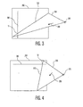
- the illustration shows the user 30 pointing to a target 260 using a pointing gesture. It has been determined experimentally that the gesture used by people to point to a target, such as the target 260, is such that the user's fingertip 235, the user's right (or left) eye 230, and a target 260 are joined by a straight line. Referring now also to Figs. 3 and 4 , the plane of the screen 210 is indicated at 350 and the line joining the eye 236 and fingertip 235 of the user 30 at 330.
- the planar projection of the target 260 in the view of the setup camera 240 lies along the planar projection of the straight line or direction vector 330 defined by the eye 236 and fingertip 235 of the user 30.
- the focal point of the camera 240 indicated at 325, along with the direction vector, define a plane 320.
- the target e.g., T1
- the target point may be obtained by finding the intersection of the planar projection 310 of the straight line 330 and the vertical axis or slider control 360.
- two axes or slider controls 360 and 365 may be projected in succession on the screen 210 and the position indicated by indicating first the vertical position on, for example, the vertical axis or slider control 360 and then the horizontal position on, for example, a horizontal axis or slider control 365. This is analogous to the way one would pick a particular cell of a table by specifying its column and then its row.
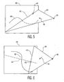
- a point can be specified on a non-straight line 460. If the projection line 410 corresponding to the direction vector 430 intersects the curve or contour 460 at one point only, then the target point can be determined unambiguously. For example, the position of a point on a road or outline of another object could be specified in this way. Again, the target is assumed to lie in a plane 450.
- a target 473 is indicated by the direction vector 430.
- the target 473 is known to lie on a path defined by the line 410 specified by the projection of the direction vector 430.
- the image's position and/or orientation are changed and the user generates another indication represented by the direction vector 430.
- a second projection line 412 is then defined in the plane 450. The intersection of the projection lines 410 and 412 indicate the location of the target 473.
- the projection lines 410 and 412 are defined relative to the scene.
- the target is indicated by a pointing gesture in a particular manner (eye-to-fingertip), there is no reason this indication could not be derived in other ways.
- a sighting device or wand could be used.
- the target could be any objects or images that substantially lie on a common plane.
- the objects or targets need not lie on a single plane, but could lie on multiple planes, each of which has a respective set of registration marks.
- the invention may also be extended by,using other transforms so that targets can lie on surfaces other than flat surfaces. Still another variation is in the manner of gesturing to indicate a direction.
- a time series of images can be used to derive a direction such as the direction of a sweep of a hand or finger over a short interval of time as would attend a moving gesture to indicate a direction.
- another suitable application would be a white-board application.
- registration marks need not be marks on a screen, but may be the corners of a screen.
- registration marks may be projected on the screen at one point during setup and then removed. The registration point coordinates may then be used to compute the transform without further reference to the registration marks until the setup is changed.
- Another application of this technology is for use in aiming a camera at the target. Once the coordinates in the reference image are known, a camera may be re-aimed and zoomed to acquire the target. This would be useful in the context of an automated videoconference system.
- An image processor 505 receives image data from a camera 501.
- Image and coordinate data may be stored in a memory 510 or non-volatile storage 520.
- the transform data once computed, may be stored in the non-volatile memory 520 and the memory 510 used in the computation of the image from the camera 501 to derive coordinates x, y of the target which may be applied to an application process 530.
- the application process may command multiple image processing steps to effect the successive target-indicating steps discussed above. Each time a target is indicated, an indicator 522, such as a voice-response system, may indicate the user's input.
- the user may indicate that his/her current gesture is completed by saying a particular word or command. Alternatively, the user may indicate the same using gesture, a remote control button, or other indicator 522.
- the application process 530 then generates an output on an output device 540, such as a trace on a whiteboard or control data for an avatar of a game.
- an RF detector 524 may be provided.
- the projection data gathered by the camera 501 could also be derived from other sources such as sonar, radio, ultrasound medical equipment or any other device that is capable of forming a planar projection.
- the identical computation methodology may be used in connection with a pointing indicator other than one whose orientation is acquired by way of cameras.
- the orientation of a sighting tube or gun-sight with radio transmitters could be acquired by a computer and used to determine the position of a target on a screen.
- the technology used for radio-based writing tablets, networked whiteboard applications, and such could be employed to determine the orientation of a pointing device avoiding the need for cameras altogether. Note that this device could also be used in WO 01/88681 A1 .
Landscapes
- Engineering & Computer Science (AREA)
- Theoretical Computer Science (AREA)
- General Engineering & Computer Science (AREA)
- Human Computer Interaction (AREA)
- Physics & Mathematics (AREA)
- General Physics & Mathematics (AREA)
- Position Input By Displaying (AREA)
- User Interface Of Digital Computer (AREA)
- Two-Way Televisions, Distribution Of Moving Picture Or The Like (AREA)
- Infusion, Injection, And Reservoir Apparatuses (AREA)
- External Artificial Organs (AREA)
- Measurement Of The Respiration, Hearing Ability, Form, And Blood Characteristics Of Living Organisms (AREA)
Claims (6)
- Procédé d'indication d'un point (260, T1, T2, 473) sur un trajet prédéterminé (360, 365, 410, 460, 462) sur un écran d'affichage (210) d'un système qui comprend :- un capteur de surveillance (200) qui est agencé de manière à capter une image d'un utilisateur (30) en face de l'écran d'affichage ; et- une mémoire (510, 520) comprenant des données de transformation pour entrer des coordonnées dans une image qui a été captée par le capteur de surveillance en des coordonnées dans une image d'installation qui a été captée à l'aide d'un capteur d'installation (240) ayant un point focal donné (325) et un champ visuel comprenant l'écran d'affichage et le capteur de surveillance, le procédé comprenant les étapes suivantes consistant à :- capter, à l'aide du capteur de surveillance, une image d'un utilisateur fournissant une direction d'orientation (235 à 236) ;- appliquer les données de transformation pour entrer des coordonnées de la direction d'orientation dans l'image qui a été captée en des coordonnées qui constituent un vecteur de direction (330, 430) ;- définir un plan (320, 420) dans lequel se situent le vecteur de direction et le point focal donné du capteur d'installation, caractérisé par l'étape suivante consistant à :déterminer une intersection (310, 312, 410, 412) du plan et du trajet prédéterminé (360, 365, 410, 460, 462) sur l'écran d'affichage, l'intersection définissant le point sur l'écran d'affichage.
- Procédé selon la revendication 1, le trajet prédéterminé étant en forme d'un régulateur à coulisse (360, 365) sur l'écran d'affichage.
- Procédé selon la revendication 1, comprenant, pour définir le trajet prédéterminé (410), les étapes préliminaires suivantes consistant à :- capter, à l'aide du capteur de surveillance (200), une image préliminaire de l'utilisateur (30) fournissant une direction préliminaire d'orientation ;- appliquer les données de transformation pour entrer des coordonnées de la direction préliminaire d'orientation dans l'image qui a été captée en des coordonnées qui constituent un vecteur préliminaire de direction (430 ; figure 5) ;- définir un plan (420 ; figure 5) dans lequel se situent le vecteur préliminaire de direction et le point focal donné (325) du capteur d'installation ; et- déterminer une intersection (410) du plan et de l'écran d'affichage, l'intersection constituant le trajet prédéterminé.
- Procédé selon la revendication 1, comprenant l'étape suivante consistant à :- afficher une scène sur l'écran d'affichage (210) tout en captant, à l'aide du capteur de surveillance (200), l'image de l'utilisateur (30) fournissant la direction d'orientation (235 à 236),
et comprenant, pour définir le trajet prédéterminé (410), les étapes préliminaires suivantes consistant à :- capter, à l'aide du capteur de surveillance, une image préliminaire de l'utilisateur fournissant une direction préliminaire d'orientation tout en affichant une vue différente de la scène par l'application, d'au moins parmi les deux suivantes opérations, la translation et la rotation ;- appliquer les données de transformation pour entrer des coordonnées de la direction préliminaire d'orientation dans l'image qui a été captée en des coordonnées qui constituent un vecteur préliminaire de direction (430 ; figure 5) ;- définir un plan (420 ; figure 5) dans lequel se situent le vecteur préliminaire de direction et le point focal donné (325) du capteur d'installation ; et- déterminer une intersection (410) du plan et de l'écran d'affichage, l'intersection définissant constituant le trajet prédéterminé. - Ordinateur de traitement de l'image :- un écran d'affichage (210) ;- un capteur de surveillance (200) qui est agencé de manière à capter une image d'un utilisateur (30) en face de l'écran d'affichage ; l'utilisateur fournissant une direction d'orientation (325 à 326) ; et- une mémoire (510, 520) comprenant des données de transformation pour entrer des coordonnées dans une image qui a été captée par le capteur de surveillance en des coordonnées dans une image d'installation qui a été captée à l'aide d'un capteur d'installation (240) ayant un point focal donné (325) et un champ visuel comprenant l'écran d'affichage et le capteur de surveillance ;- un contrôleur (505) qui a été programmé de manière à :- appliquer les données de transformation de manière à entrer des coordonnées de la direction d'orientation dans l'image qui a été captée en des coordonnées qui constituent un vecteur de direction (330, 430) ;- définir un plan (320, 420) dans lequel se situent le vecteur de direction et le point focal donné du capteur d'installation, caractérisé par l'étape suivante consistant à :déterminer une intersection (310, 410) du plan et du traj et prédéterminé (360, 365, 410, 460, 462) sur l'écran d'affichage, l'intersection indiquant un point (260, T1, T2, 473) sur l'écran d'affichage.
- Produit de programme informatique pour un système, comprenant :- un écran d'affichage (210) ;- un capteur de surveillance (200) qui est agencé de manière à capter une image d'un utilisateur (30) en face de l'écran d'affichage ;- une mémoire (510, 520) comprenant des données de transformation pour entrer des coordonnées dans une image qui a été captée par le capteur de surveillance en des coordonnées dans une image d'installation qui a été captée à l'aide d'un capteur d'installation ayant un point focal donné (325) et un champ visuel comprenant l'écran d'affichage et le capteur de surveillance ; et- un contrôleur (505),
le produit de programme informatique comprenant un ensemble d'instructions qui effectuent, lorsqu'elles sont chargées dans le système, que le contrôleur réalise les étapes qui sont définies dans le procédé selon la revendication 1.
Applications Claiming Priority (2)
| Application Number | Priority Date | Filing Date | Title |
|---|---|---|---|
| US09/766,710 US6600475B2 (en) | 2001-01-22 | 2001-01-22 | Single camera system for gesture-based input and target indication |
| PCT/IB2001/002589 WO2002057894A2 (fr) | 2001-01-22 | 2001-12-17 | Systeme a camera unique permettant d'effectuer une entree a base de gestes et d'indiquer une cible |
Publications (2)
| Publication Number | Publication Date |
|---|---|
| EP1629366A2 EP1629366A2 (fr) | 2006-03-01 |
| EP1629366B1 true EP1629366B1 (fr) | 2009-11-04 |
Family
ID=25077269
Family Applications (1)
| Application Number | Title | Priority Date | Filing Date |
|---|---|---|---|
| EP01273319A Expired - Lifetime EP1629366B1 (fr) | 2001-01-22 | 2001-12-17 | Systeme a camera unique permettant d'effectuer une entree a base de gestes et d'indiquer une cible |
Country Status (8)
| Country | Link |
|---|---|
| US (1) | US6600475B2 (fr) |
| EP (1) | EP1629366B1 (fr) |
| JP (1) | JP4278979B2 (fr) |
| KR (1) | KR100878127B1 (fr) |
| CN (1) | CN1307510C (fr) |
| AT (1) | ATE447735T1 (fr) |
| DE (1) | DE60140387D1 (fr) |
| WO (1) | WO2002057894A2 (fr) |
Families Citing this family (115)
| Publication number | Priority date | Publication date | Assignee | Title |
|---|---|---|---|---|
| US8352400B2 (en) | 1991-12-23 | 2013-01-08 | Hoffberg Steven M | Adaptive pattern recognition based controller apparatus and method and human-factored interface therefore |
| US7966078B2 (en) | 1999-02-01 | 2011-06-21 | Steven Hoffberg | Network media appliance system and method |
| US6943774B2 (en) * | 2001-04-02 | 2005-09-13 | Matsushita Electric Industrial Co., Ltd. | Portable communication terminal, information display device, control input device and control input method |
| JP3811025B2 (ja) * | 2001-07-03 | 2006-08-16 | 株式会社日立製作所 | ネットワーク・システム |
| US6990639B2 (en) * | 2002-02-07 | 2006-01-24 | Microsoft Corporation | System and process for controlling electronic components in a ubiquitous computing environment using multimodal integration |
| US8745541B2 (en) | 2003-03-25 | 2014-06-03 | Microsoft Corporation | Architecture for controlling a computer using hand gestures |
| US7665041B2 (en) * | 2003-03-25 | 2010-02-16 | Microsoft Corporation | Architecture for controlling a computer using hand gestures |
| US7038661B2 (en) * | 2003-06-13 | 2006-05-02 | Microsoft Corporation | Pointing device and cursor for use in intelligent computing environments |
| GB2407635B (en) * | 2003-10-31 | 2006-07-12 | Hewlett Packard Development Co | Improvements in and relating to camera control |
| US8442331B2 (en) | 2004-02-15 | 2013-05-14 | Google Inc. | Capturing text from rendered documents using supplemental information |
| US7707039B2 (en) | 2004-02-15 | 2010-04-27 | Exbiblio B.V. | Automatic modification of web pages |
| US7812860B2 (en) | 2004-04-01 | 2010-10-12 | Exbiblio B.V. | Handheld device for capturing text from both a document printed on paper and a document displayed on a dynamic display device |
| US10635723B2 (en) | 2004-02-15 | 2020-04-28 | Google Llc | Search engines and systems with handheld document data capture devices |
| US7969409B2 (en) * | 2004-02-18 | 2011-06-28 | Rafal Jan Krepec | Camera assisted pen tablet |
| JP4566596B2 (ja) * | 2004-03-29 | 2010-10-20 | アルパイン株式会社 | 操作指示装置 |
| US20050227217A1 (en) * | 2004-03-31 | 2005-10-13 | Wilson Andrew D | Template matching on interactive surface |
| US7990556B2 (en) | 2004-12-03 | 2011-08-02 | Google Inc. | Association of a portable scanner with input/output and storage devices |
| US20060081714A1 (en) | 2004-08-23 | 2006-04-20 | King Martin T | Portable scanning device |
| US9008447B2 (en) | 2004-04-01 | 2015-04-14 | Google Inc. | Method and system for character recognition |
| US20060098900A1 (en) | 2004-09-27 | 2006-05-11 | King Martin T | Secure data gathering from rendered documents |
| US9143638B2 (en) | 2004-04-01 | 2015-09-22 | Google Inc. | Data capture from rendered documents using handheld device |
| US7894670B2 (en) | 2004-04-01 | 2011-02-22 | Exbiblio B.V. | Triggering actions in response to optically or acoustically capturing keywords from a rendered document |
| WO2008028674A2 (fr) | 2006-09-08 | 2008-03-13 | Exbiblio B.V. | Scanners optiques, tels que des scanners optiques portables |
| US8146156B2 (en) | 2004-04-01 | 2012-03-27 | Google Inc. | Archive of text captures from rendered documents |
| US9116890B2 (en) | 2004-04-01 | 2015-08-25 | Google Inc. | Triggering actions in response to optically or acoustically capturing keywords from a rendered document |
| US8081849B2 (en) | 2004-12-03 | 2011-12-20 | Google Inc. | Portable scanning and memory device |
| US8713418B2 (en) | 2004-04-12 | 2014-04-29 | Google Inc. | Adding value to a rendered document |
| US8489624B2 (en) | 2004-05-17 | 2013-07-16 | Google, Inc. | Processing techniques for text capture from a rendered document |
| US8620083B2 (en) | 2004-12-03 | 2013-12-31 | Google Inc. | Method and system for character recognition |
| US8874504B2 (en) | 2004-12-03 | 2014-10-28 | Google Inc. | Processing techniques for visual capture data from a rendered document |
| US7394459B2 (en) | 2004-04-29 | 2008-07-01 | Microsoft Corporation | Interaction between objects and a virtual environment display |
| US7893920B2 (en) * | 2004-05-06 | 2011-02-22 | Alpine Electronics, Inc. | Operation input device and method of operation input |
| US7338449B2 (en) * | 2004-05-25 | 2008-03-04 | Siemens Medical Solutions Usa, Inc. | Three dimensional locator for diagnostic ultrasound or medical imaging |
| US7787706B2 (en) * | 2004-06-14 | 2010-08-31 | Microsoft Corporation | Method for controlling an intensity of an infrared source used to detect objects adjacent to an interactive display surface |
| US7593593B2 (en) | 2004-06-16 | 2009-09-22 | Microsoft Corporation | Method and system for reducing effects of undesired signals in an infrared imaging system |
| US8346620B2 (en) | 2004-07-19 | 2013-01-01 | Google Inc. | Automatic modification of web pages |
| US8560972B2 (en) | 2004-08-10 | 2013-10-15 | Microsoft Corporation | Surface UI for gesture-based interaction |
| US20060072009A1 (en) * | 2004-10-01 | 2006-04-06 | International Business Machines Corporation | Flexible interaction-based computer interfacing using visible artifacts |
| KR100663515B1 (ko) * | 2004-11-08 | 2007-01-02 | 삼성전자주식회사 | 휴대 단말 장치 및 이를 위한 데이터 입력 방법 |
| US7852317B2 (en) | 2005-01-12 | 2010-12-14 | Thinkoptics, Inc. | Handheld device for handheld vision based absolute pointing system |
| KR100724939B1 (ko) * | 2005-06-20 | 2007-06-04 | 삼성전자주식회사 | 카메라부를 이용한 유저 인터페이스 구현 방법 및 이를위한 이동통신단말기 |
| US20070018966A1 (en) * | 2005-07-25 | 2007-01-25 | Blythe Michael M | Predicted object location |
| US7911444B2 (en) | 2005-08-31 | 2011-03-22 | Microsoft Corporation | Input method for surface of interactive display |
| US7697827B2 (en) | 2005-10-17 | 2010-04-13 | Konicek Jeffrey C | User-friendlier interfaces for a camera |
| US8060840B2 (en) | 2005-12-29 | 2011-11-15 | Microsoft Corporation | Orientation free user interface |
| US7984995B2 (en) * | 2006-05-24 | 2011-07-26 | Smart Technologies Ulc | Method and apparatus for inhibiting a subject's eyes from being exposed to projected light |
| US8913003B2 (en) | 2006-07-17 | 2014-12-16 | Thinkoptics, Inc. | Free-space multi-dimensional absolute pointer using a projection marker system |
| US7907117B2 (en) | 2006-08-08 | 2011-03-15 | Microsoft Corporation | Virtual controller for visual displays |
| US7770115B2 (en) * | 2006-11-07 | 2010-08-03 | Polycom, Inc. | System and method for controlling presentations and videoconferences using hand motions |
| US20110025818A1 (en) * | 2006-11-07 | 2011-02-03 | Jonathan Gallmeier | System and Method for Controlling Presentations and Videoconferences Using Hand Motions |
| JP4171040B2 (ja) | 2006-12-22 | 2008-10-22 | 株式会社コナミデジタルエンタテインメント | ゲーム装置、ゲーム装置の制御方法及びプログラム |
| JP4171039B2 (ja) * | 2006-12-22 | 2008-10-22 | 株式会社コナミデジタルエンタテインメント | ゲーム装置、ゲーム装置の制御方法及びプログラム |
| US8212857B2 (en) * | 2007-01-26 | 2012-07-03 | Microsoft Corporation | Alternating light sources to reduce specular reflection |
| US9176598B2 (en) | 2007-05-08 | 2015-11-03 | Thinkoptics, Inc. | Free-space multi-dimensional absolute pointer with improved performance |
| US8726194B2 (en) | 2007-07-27 | 2014-05-13 | Qualcomm Incorporated | Item selection using enhanced control |
| US20110035662A1 (en) | 2009-02-18 | 2011-02-10 | King Martin T | Interacting with rendered documents using a multi-function mobile device, such as a mobile phone |
| TW200919336A (en) * | 2007-10-25 | 2009-05-01 | Ind Tech Res Inst | Method for positioning a non-structural object in a series of continuing images |
| US9171454B2 (en) * | 2007-11-14 | 2015-10-27 | Microsoft Technology Licensing, Llc | Magic wand |
| WO2009089045A1 (fr) * | 2008-01-08 | 2009-07-16 | Kessler Jonathan A | Procédé d'interaction et de communication basées sur l'image |
| US20100031202A1 (en) * | 2008-08-04 | 2010-02-04 | Microsoft Corporation | User-defined gesture set for surface computing |
| US8847739B2 (en) * | 2008-08-04 | 2014-09-30 | Microsoft Corporation | Fusing RFID and vision for surface object tracking |
| US8305345B2 (en) * | 2008-08-07 | 2012-11-06 | Life Technologies Co., Ltd. | Multimedia playing device |
| US9310992B2 (en) * | 2008-08-22 | 2016-04-12 | Google Inc. | Panning in a three dimensional environment on a mobile device |
| US20100105479A1 (en) | 2008-10-23 | 2010-04-29 | Microsoft Corporation | Determining orientation in an external reference frame |
| WO2010105245A2 (fr) | 2009-03-12 | 2010-09-16 | Exbiblio B.V. | Fourniture automatique de contenu associé à des informations capturées, de type informations capturées en temps réel |
| US8447066B2 (en) | 2009-03-12 | 2013-05-21 | Google Inc. | Performing actions based on capturing information from rendered documents, such as documents under copyright |
| US9417700B2 (en) | 2009-05-21 | 2016-08-16 | Edge3 Technologies | Gesture recognition systems and related methods |
| US8547327B2 (en) | 2009-10-07 | 2013-10-01 | Qualcomm Incorporated | Proximity object tracker |
| US9081799B2 (en) | 2009-12-04 | 2015-07-14 | Google Inc. | Using gestalt information to identify locations in printed information |
| US9323784B2 (en) | 2009-12-09 | 2016-04-26 | Google Inc. | Image search using text-based elements within the contents of images |
| US9189949B2 (en) | 2010-12-09 | 2015-11-17 | Sealed Air Corporation (Us) | Automated monitoring and control of contamination in a production area |
| US9143843B2 (en) | 2010-12-09 | 2015-09-22 | Sealed Air Corporation | Automated monitoring and control of safety in a production area |
| US9406212B2 (en) | 2010-04-01 | 2016-08-02 | Sealed Air Corporation (Us) | Automated monitoring and control of contamination activity in a production area |
| US8396252B2 (en) | 2010-05-20 | 2013-03-12 | Edge 3 Technologies | Systems and related methods for three dimensional gesture recognition in vehicles |
| US8649592B2 (en) | 2010-08-30 | 2014-02-11 | University Of Illinois At Urbana-Champaign | System for background subtraction with 3D camera |
| US8582866B2 (en) | 2011-02-10 | 2013-11-12 | Edge 3 Technologies, Inc. | Method and apparatus for disparity computation in stereo images |
| US8655093B2 (en) | 2010-09-02 | 2014-02-18 | Edge 3 Technologies, Inc. | Method and apparatus for performing segmentation of an image |
| US8467599B2 (en) | 2010-09-02 | 2013-06-18 | Edge 3 Technologies, Inc. | Method and apparatus for confusion learning |
| US8666144B2 (en) | 2010-09-02 | 2014-03-04 | Edge 3 Technologies, Inc. | Method and apparatus for determining disparity of texture |
| US9011607B2 (en) | 2010-10-07 | 2015-04-21 | Sealed Air Corporation (Us) | Automated monitoring and control of cleaning in a production area |
| US20120095575A1 (en) * | 2010-10-14 | 2012-04-19 | Cedes Safety & Automation Ag | Time of flight (tof) human machine interface (hmi) |
| US8970589B2 (en) | 2011-02-10 | 2015-03-03 | Edge 3 Technologies, Inc. | Near-touch interaction with a stereo camera grid structured tessellations |
| US8928589B2 (en) * | 2011-04-20 | 2015-01-06 | Qualcomm Incorporated | Virtual keyboards and methods of providing the same |
| KR101804848B1 (ko) | 2011-04-22 | 2017-12-06 | 삼성전자주식회사 | 비디오 객체 탐색 장치, 비디오 객체 변형 장치 및 그 방법 |
| WO2012171116A1 (fr) | 2011-06-16 | 2012-12-20 | Rafal Jan Krepec | Rétroaction visuelle par identification de caractéristiques anatomiques d'une main |
| US9672609B1 (en) | 2011-11-11 | 2017-06-06 | Edge 3 Technologies, Inc. | Method and apparatus for improved depth-map estimation |
| US8811938B2 (en) | 2011-12-16 | 2014-08-19 | Microsoft Corporation | Providing a user interface experience based on inferred vehicle state |
| US9336456B2 (en) | 2012-01-25 | 2016-05-10 | Bruno Delean | Systems, methods and computer program products for identifying objects in video data |
| US20130204408A1 (en) * | 2012-02-06 | 2013-08-08 | Honeywell International Inc. | System for controlling home automation system using body movements |
| CN103294173A (zh) * | 2012-02-24 | 2013-09-11 | 冠捷投资有限公司 | 基于使用者动作的遥控系统及其方法 |
| CN104471511B (zh) * | 2012-03-13 | 2018-04-20 | 视力移动技术有限公司 | 识别指点手势的装置、用户接口和方法 |
| KR101533320B1 (ko) * | 2012-04-23 | 2015-07-03 | 주식회사 브이터치 | 포인터가 불필요한 3차원 객체 정보 획득 장치 |
| CN103873760B (zh) * | 2012-12-17 | 2017-12-26 | 联想(北京)有限公司 | 一种对焦点调整方法及电子设备 |
| TWI486820B (zh) * | 2012-12-28 | 2015-06-01 | Wistron Corp | 用於互動系統之座標轉換方法及電腦系統 |
| US8933882B2 (en) * | 2012-12-31 | 2015-01-13 | Intentive Inc. | User centric interface for interaction with visual display that recognizes user intentions |
| US9141198B2 (en) * | 2013-01-08 | 2015-09-22 | Infineon Technologies Ag | Control of a control parameter by gesture recognition |
| US10721448B2 (en) | 2013-03-15 | 2020-07-21 | Edge 3 Technologies, Inc. | Method and apparatus for adaptive exposure bracketing, segmentation and scene organization |
| JP6171452B2 (ja) * | 2013-03-25 | 2017-08-02 | セイコーエプソン株式会社 | 画像処理装置、プロジェクターおよび画像処理方法 |
| TWI563818B (en) * | 2013-05-24 | 2016-12-21 | Univ Central Taiwan Sci & Tech | Three dimension contactless controllable glasses-like cell phone |
| CN110442231A (zh) * | 2013-06-27 | 2019-11-12 | 视力移动科技公司 | 用于与数字设备交互的直接指向检测的系统和方法 |
| CN105531646A (zh) | 2013-09-17 | 2016-04-27 | 皇家飞利浦有限公司 | 手势驱动的范围和值的同时选择 |
| KR101533319B1 (ko) * | 2014-02-22 | 2015-07-03 | 주식회사 브이터치 | 카메라 중심의 가상터치를 이용한 원격 조작 장치 및 방법 |
| CN104978012B (zh) | 2014-04-03 | 2018-03-16 | 华为技术有限公司 | 一种指向交互方法、装置及系统 |
| KR101453815B1 (ko) | 2014-08-01 | 2014-10-22 | 스타십벤딩머신 주식회사 | 사용자의 시점을 고려하여 동작인식하는 인터페이스 제공방법 및 제공장치 |
| DE102015201728A1 (de) * | 2015-02-02 | 2016-08-04 | Bayerische Motoren Werke Aktiengesellschaft | Verfahren zum Auswählen eines Bedienelements eines Kraftfahrzeugs und Bediensystem für ein Kraftfahrzeug |
| CN107787497B (zh) * | 2015-06-10 | 2021-06-22 | 维塔驰有限公司 | 用于在基于用户的空间坐标系中检测手势的方法和装置 |
| US10860843B1 (en) | 2015-08-22 | 2020-12-08 | Bertec Corporation | Measurement system that includes at least one measurement assembly, a head-mounted visual display device, and a data processing device |
| US10216262B1 (en) * | 2015-08-22 | 2019-02-26 | Bertec Corporation | Force management system that includes a force measurement assembly, a visual display device, and one or more data processing devices |
| US10555688B1 (en) | 2015-08-22 | 2020-02-11 | Bertec Corporation | Measurement system that includes at least one measurement assembly, a head-mounted visual display device, and a data processing device |
| US11301045B1 (en) | 2015-08-22 | 2022-04-12 | Bertec Corporation | Measurement system that includes at least one measurement assembly, a visual display device, and at least one data processing device |
| US10390736B1 (en) | 2015-08-22 | 2019-08-27 | Bertec Corporation | Force measurement system that includes a force measurement assembly, at least one visual display device, and one or more data processing devices |
| TWI553509B (zh) * | 2015-10-30 | 2016-10-11 | 鴻海精密工業股份有限公司 | 手勢控制系統及方法 |
| US11604517B2 (en) * | 2016-09-02 | 2023-03-14 | Rakuten Group, Inc. | Information processing device, information processing method for a gesture control user interface |
| CN107346175B (zh) * | 2017-06-30 | 2020-08-25 | 联想(北京)有限公司 | 一种手势位置校正方法和增强现实显示设备 |
| CN110554784B (zh) * | 2018-05-31 | 2023-07-14 | 广东虚拟现实科技有限公司 | 输入方法、装置、显示设备及存储介质 |
Family Cites Families (13)
| Publication number | Priority date | Publication date | Assignee | Title |
|---|---|---|---|---|
| FR2695745B1 (fr) | 1992-09-15 | 1994-10-28 | Sextant Avionique | Procédé de dialogue gestuel multimode dans un environnement virtuel. |
| FR2696574B1 (fr) | 1992-10-06 | 1994-11-18 | Sextant Avionique | Procédé et dispositif d'analyse d'un message fourni par des moyens d'interaction à un système de dialogue homme-machine. |
| US5454043A (en) | 1993-07-30 | 1995-09-26 | Mitsubishi Electric Research Laboratories, Inc. | Dynamic and static hand gesture recognition through low-level image analysis |
| JP3267047B2 (ja) | 1994-04-25 | 2002-03-18 | 株式会社日立製作所 | 音声による情報処理装置 |
| JP3270643B2 (ja) * | 1994-12-22 | 2002-04-02 | キヤノン株式会社 | 指示位置検出方法及び装置 |
| US5594469A (en) | 1995-02-21 | 1997-01-14 | Mitsubishi Electric Information Technology Center America Inc. | Hand gesture machine control system |
| WO1996034332A1 (fr) | 1995-04-28 | 1996-10-31 | Matsushita Electric Industrial Co., Ltd. | Dispositif d'interface |
| US6176782B1 (en) | 1997-12-22 | 2001-01-23 | Philips Electronics North America Corp. | Motion-based command generation technology |
| JP3795647B2 (ja) * | 1997-10-29 | 2006-07-12 | 株式会社竹中工務店 | ハンドポインティング装置 |
| US6353764B1 (en) | 1997-11-27 | 2002-03-05 | Matsushita Electric Industrial Co., Ltd. | Control method |
| DE19845028A1 (de) | 1998-09-30 | 2000-06-08 | Siemens Ag | Magnetresonanz (MR)-System |
| US6147678A (en) * | 1998-12-09 | 2000-11-14 | Lucent Technologies Inc. | Video hand image-three-dimensional computer interface with multiple degrees of freedom |
| WO2001088681A1 (fr) | 2000-05-17 | 2001-11-22 | Koninklijke Philips Electronics N.V. | Dispositif et procede servant a indiquer une cible par traitement d'image sans modelisation tridimensionnelle |
-
2001
- 2001-01-22 US US09/766,710 patent/US6600475B2/en not_active Expired - Lifetime
- 2001-12-17 AT AT01273319T patent/ATE447735T1/de not_active IP Right Cessation
- 2001-12-17 DE DE60140387T patent/DE60140387D1/de not_active Expired - Lifetime
- 2001-12-17 KR KR1020027012389A patent/KR100878127B1/ko active IP Right Grant
- 2001-12-17 WO PCT/IB2001/002589 patent/WO2002057894A2/fr active Application Filing
- 2001-12-17 EP EP01273319A patent/EP1629366B1/fr not_active Expired - Lifetime
- 2001-12-17 JP JP2002558112A patent/JP4278979B2/ja not_active Expired - Fee Related
- 2001-12-17 CN CNB018069614A patent/CN1307510C/zh not_active Expired - Fee Related
Also Published As
| Publication number | Publication date |
|---|---|
| US20020097218A1 (en) | 2002-07-25 |
| ATE447735T1 (de) | 2009-11-15 |
| CN1636178A (zh) | 2005-07-06 |
| JP4278979B2 (ja) | 2009-06-17 |
| WO2002057894A3 (fr) | 2007-11-08 |
| CN1307510C (zh) | 2007-03-28 |
| US6600475B2 (en) | 2003-07-29 |
| KR100878127B1 (ko) | 2009-01-14 |
| WO2002057894A2 (fr) | 2002-07-25 |
| EP1629366A2 (fr) | 2006-03-01 |
| KR20020086931A (ko) | 2002-11-20 |
| DE60140387D1 (de) | 2009-12-17 |
| JP2004522220A (ja) | 2004-07-22 |
Similar Documents
| Publication | Publication Date | Title |
|---|---|---|
| EP1629366B1 (fr) | Systeme a camera unique permettant d'effectuer une entree a base de gestes et d'indiquer une cible | |
| US11396100B2 (en) | Robot calibration for AR and digital twin | |
| Ong et al. | Augmented reality-assisted robot programming system for industrial applications | |
| US10888998B2 (en) | Method and device for verifying one or more safety volumes for a movable mechanical unit | |
| EP1292877B1 (fr) | Dispositif et procede servant a indiquer une cible par traitement d'image sans modelisation tridimensionnelle | |
| US11724388B2 (en) | Robot controller and display device using augmented reality and mixed reality | |
| US10585167B2 (en) | Relative object localization process for local positioning system | |
| EP1215017B1 (fr) | Dispositif d'apprentissage pour robot | |
| US7236854B2 (en) | Method and a system for programming an industrial robot | |
| EP1435280B1 (fr) | Procédé et système de programmation d'un robot industriel | |
| US20110010009A1 (en) | Action teaching system and action teaching method | |
| US20050131582A1 (en) | Process and device for determining the position and the orientation of an image reception means | |
| US20150202776A1 (en) | Data generation device for vision sensor and detection simulation system | |
| JP2001060108A (ja) | ロボット動作教示装置および動作教示方法 | |
| JPH08254409A (ja) | 三次元形状計測解析法 | |
| JPH0847881A (ja) | ロボットの遠隔操作方法 | |
| WO2017007492A1 (fr) | Systèmes d'affichage pour machine et de commande de machine | |
| CN113597362A (zh) | 用于确定机器人坐标系与可移动装置坐标系之间的关系的方法和控制装置 | |
| CN112454363A (zh) | 一种用于焊接操作的ar辅助机器人的控制方法 | |
| US20160011675A1 (en) | Absolute Position 3D Pointing using Light Tracking and Relative Position Detection | |
| US20230409149A1 (en) | Virtual buttons for augmented reality light guided assembly system and calibration method | |
| JPH05329793A (ja) | 視覚センサ | |
| WO2023073562A1 (fr) | Appareil et procédé de programmation de robots par démonstration | |
| CN116075800A (zh) | 用于向用户输入提供反馈的方法和设备 | |
| CN110554784A (zh) | 输入方法、装置、显示设备及存储介质 |
Legal Events
| Date | Code | Title | Description |
|---|---|---|---|
| PUAI | Public reference made under article 153(3) epc to a published international application that has entered the european phase |
Free format text: ORIGINAL CODE: 0009012 |
|
| AK | Designated contracting states |
Kind code of ref document: A2 Designated state(s): AT BE CH CY DE DK ES FI FR GB GR IE IT LI LU MC NL PT SE TR |
|
| PUAK | Availability of information related to the publication of the international search report |
Free format text: ORIGINAL CODE: 0009015 |
|
| 17P | Request for examination filed |
Effective date: 20080508 |
|
| RBV | Designated contracting states (corrected) |
Designated state(s): AT BE CH CY DE DK ES FI FR GB GR IE IT LI LU MC NL PT SE TR |
|
| 17Q | First examination report despatched |
Effective date: 20080620 |
|
| GRAP | Despatch of communication of intention to grant a patent |
Free format text: ORIGINAL CODE: EPIDOSNIGR1 |
|
| RIC1 | Information provided on ipc code assigned before grant |
Ipc: G06F 3/042 20060101AFI20090505BHEP |
|
| GRAS | Grant fee paid |
Free format text: ORIGINAL CODE: EPIDOSNIGR3 |
|
| GRAA | (expected) grant |
Free format text: ORIGINAL CODE: 0009210 |
|
| AK | Designated contracting states |
Kind code of ref document: B1 Designated state(s): AT BE CH CY DE DK ES FI FR GB GR IE IT LI LU MC NL PT SE TR |
|
| REG | Reference to a national code |
Ref country code: GB Ref legal event code: FG4D |
|
| REG | Reference to a national code |
Ref country code: CH Ref legal event code: EP |
|
| REG | Reference to a national code |
Ref country code: IE Ref legal event code: FG4D |
|
| REF | Corresponds to: |
Ref document number: 60140387 Country of ref document: DE Date of ref document: 20091217 Kind code of ref document: P |
|
| NLV1 | Nl: lapsed or annulled due to failure to fulfill the requirements of art. 29p and 29m of the patents act | ||
| PG25 | Lapsed in a contracting state [announced via postgrant information from national office to epo] |
Ref country code: ES Free format text: LAPSE BECAUSE OF FAILURE TO SUBMIT A TRANSLATION OF THE DESCRIPTION OR TO PAY THE FEE WITHIN THE PRESCRIBED TIME-LIMIT Effective date: 20100215 Ref country code: SE Free format text: LAPSE BECAUSE OF FAILURE TO SUBMIT A TRANSLATION OF THE DESCRIPTION OR TO PAY THE FEE WITHIN THE PRESCRIBED TIME-LIMIT Effective date: 20091104 Ref country code: FI Free format text: LAPSE BECAUSE OF FAILURE TO SUBMIT A TRANSLATION OF THE DESCRIPTION OR TO PAY THE FEE WITHIN THE PRESCRIBED TIME-LIMIT Effective date: 20091104 Ref country code: PT Free format text: LAPSE BECAUSE OF FAILURE TO SUBMIT A TRANSLATION OF THE DESCRIPTION OR TO PAY THE FEE WITHIN THE PRESCRIBED TIME-LIMIT Effective date: 20100304 |
|
| PG25 | Lapsed in a contracting state [announced via postgrant information from national office to epo] |
Ref country code: CY Free format text: LAPSE BECAUSE OF FAILURE TO SUBMIT A TRANSLATION OF THE DESCRIPTION OR TO PAY THE FEE WITHIN THE PRESCRIBED TIME-LIMIT Effective date: 20091104 |
|
| PG25 | Lapsed in a contracting state [announced via postgrant information from national office to epo] |
Ref country code: AT Free format text: LAPSE BECAUSE OF FAILURE TO SUBMIT A TRANSLATION OF THE DESCRIPTION OR TO PAY THE FEE WITHIN THE PRESCRIBED TIME-LIMIT Effective date: 20091104 Ref country code: BE Free format text: LAPSE BECAUSE OF FAILURE TO SUBMIT A TRANSLATION OF THE DESCRIPTION OR TO PAY THE FEE WITHIN THE PRESCRIBED TIME-LIMIT Effective date: 20091104 |
|
| PG25 | Lapsed in a contracting state [announced via postgrant information from national office to epo] |
Ref country code: MC Free format text: LAPSE BECAUSE OF NON-PAYMENT OF DUE FEES Effective date: 20100701 Ref country code: DK Free format text: LAPSE BECAUSE OF FAILURE TO SUBMIT A TRANSLATION OF THE DESCRIPTION OR TO PAY THE FEE WITHIN THE PRESCRIBED TIME-LIMIT Effective date: 20091104 |
|
| REG | Reference to a national code |
Ref country code: CH Ref legal event code: PL |
|
| PLBE | No opposition filed within time limit |
Free format text: ORIGINAL CODE: 0009261 |
|
| STAA | Information on the status of an ep patent application or granted ep patent |
Free format text: STATUS: NO OPPOSITION FILED WITHIN TIME LIMIT |
|
| 26N | No opposition filed |
Effective date: 20100805 |
|
| PG25 | Lapsed in a contracting state [announced via postgrant information from national office to epo] |
Ref country code: CH Free format text: LAPSE BECAUSE OF NON-PAYMENT OF DUE FEES Effective date: 20091231 Ref country code: GR Free format text: LAPSE BECAUSE OF FAILURE TO SUBMIT A TRANSLATION OF THE DESCRIPTION OR TO PAY THE FEE WITHIN THE PRESCRIBED TIME-LIMIT Effective date: 20100205 Ref country code: IE Free format text: LAPSE BECAUSE OF NON-PAYMENT OF DUE FEES Effective date: 20091217 Ref country code: LI Free format text: LAPSE BECAUSE OF NON-PAYMENT OF DUE FEES Effective date: 20091231 |
|
| PG25 | Lapsed in a contracting state [announced via postgrant information from national office to epo] |
Ref country code: IT Free format text: LAPSE BECAUSE OF FAILURE TO SUBMIT A TRANSLATION OF THE DESCRIPTION OR TO PAY THE FEE WITHIN THE PRESCRIBED TIME-LIMIT Effective date: 20091104 |
|
| PG25 | Lapsed in a contracting state [announced via postgrant information from national office to epo] |
Ref country code: LU Free format text: LAPSE BECAUSE OF NON-PAYMENT OF DUE FEES Effective date: 20091217 |
|
| PG25 | Lapsed in a contracting state [announced via postgrant information from national office to epo] |
Ref country code: TR Free format text: LAPSE BECAUSE OF FAILURE TO SUBMIT A TRANSLATION OF THE DESCRIPTION OR TO PAY THE FEE WITHIN THE PRESCRIBED TIME-LIMIT Effective date: 20091104 |
|
| PG25 | Lapsed in a contracting state [announced via postgrant information from national office to epo] |
Ref country code: NL Free format text: LAPSE BECAUSE OF FAILURE TO SUBMIT A TRANSLATION OF THE DESCRIPTION OR TO PAY THE FEE WITHIN THE PRESCRIBED TIME-LIMIT Effective date: 20091104 |
|
| REG | Reference to a national code |
Ref country code: DE Ref legal event code: R082 Ref document number: 60140387 Country of ref document: DE Representative=s name: VOLMER, GEORG, DIPL.-ING., DE |
|
| REG | Reference to a national code |
Ref country code: DE Ref legal event code: R082 Ref document number: 60140387 Country of ref document: DE Representative=s name: MEISSNER BOLTE PATENTANWAELTE RECHTSANWAELTE P, DE Effective date: 20140328 Ref country code: DE Ref legal event code: R081 Ref document number: 60140387 Country of ref document: DE Owner name: KONINKLIJKE PHILIPS N.V., NL Free format text: FORMER OWNER: KONINKLIJKE PHILIPS ELECTRONICS N.V., EINDHOVEN, NL Effective date: 20140328 Ref country code: DE Ref legal event code: R082 Ref document number: 60140387 Country of ref document: DE Representative=s name: VOLMER, GEORG, DIPL.-ING., DE Effective date: 20140328 Ref country code: DE Ref legal event code: R082 Ref document number: 60140387 Country of ref document: DE Representative=s name: MEISSNER, BOLTE & PARTNER GBR, DE Effective date: 20140328 |
|
| REG | Reference to a national code |
Ref country code: FR Ref legal event code: CD Owner name: KONINKLIJKE PHILIPS ELECTRONICS N.V., NL Effective date: 20141126 Ref country code: FR Ref legal event code: CA Effective date: 20141126 |
|
| REG | Reference to a national code |
Ref country code: FR Ref legal event code: PLFP Year of fee payment: 15 |
|
| REG | Reference to a national code |
Ref country code: DE Ref legal event code: R082 Ref document number: 60140387 Country of ref document: DE Representative=s name: MEISSNER BOLTE PATENTANWAELTE RECHTSANWAELTE P, DE Ref country code: DE Ref legal event code: R082 Ref document number: 60140387 Country of ref document: DE Representative=s name: MEISSNER, BOLTE & PARTNER GBR, DE |
|
| REG | Reference to a national code |
Ref country code: FR Ref legal event code: PLFP Year of fee payment: 16 |
|
| REG | Reference to a national code |
Ref country code: FR Ref legal event code: PLFP Year of fee payment: 17 |
|
| PGFP | Annual fee paid to national office [announced via postgrant information from national office to epo] |
Ref country code: GB Payment date: 20181221 Year of fee payment: 18 Ref country code: FR Payment date: 20181231 Year of fee payment: 18 |
|
| PGFP | Annual fee paid to national office [announced via postgrant information from national office to epo] |
Ref country code: DE Payment date: 20190228 Year of fee payment: 18 |
|
| REG | Reference to a national code |
Ref country code: DE Ref legal event code: R119 Ref document number: 60140387 Country of ref document: DE |
|
| GBPC | Gb: european patent ceased through non-payment of renewal fee |
Effective date: 20191217 |
|
| PG25 | Lapsed in a contracting state [announced via postgrant information from national office to epo] |
Ref country code: FR Free format text: LAPSE BECAUSE OF NON-PAYMENT OF DUE FEES Effective date: 20191231 Ref country code: DE Free format text: LAPSE BECAUSE OF NON-PAYMENT OF DUE FEES Effective date: 20200701 Ref country code: GB Free format text: LAPSE BECAUSE OF NON-PAYMENT OF DUE FEES Effective date: 20191217 |