EP1628896B1 - Lateral conveyor and mobile chassis comprising such a lateral conveyor - Google Patents
Lateral conveyor and mobile chassis comprising such a lateral conveyor Download PDFInfo
- Publication number
- EP1628896B1 EP1628896B1 EP04730598A EP04730598A EP1628896B1 EP 1628896 B1 EP1628896 B1 EP 1628896B1 EP 04730598 A EP04730598 A EP 04730598A EP 04730598 A EP04730598 A EP 04730598A EP 1628896 B1 EP1628896 B1 EP 1628896B1
- Authority
- EP
- European Patent Office
- Prior art keywords
- mounting arm
- conveyor according
- lateral conveyor
- section
- mounting
- Prior art date
- Legal status (The legal status is an assumption and is not a legal conclusion. Google has not performed a legal analysis and makes no representation as to the accuracy of the status listed.)
- Expired - Lifetime
Links
- 238000012423 maintenance Methods 0.000 claims description 6
- 229910001209 Low-carbon steel Inorganic materials 0.000 claims description 2
- 239000000463 material Substances 0.000 description 21
- 239000002689 soil Substances 0.000 description 3
- 239000004567 concrete Substances 0.000 description 2
- -1 gravel Substances 0.000 description 2
- 238000012216 screening Methods 0.000 description 2
- 239000010426 asphalt Substances 0.000 description 1
- 230000033228 biological regulation Effects 0.000 description 1
- 230000005540 biological transmission Effects 0.000 description 1
- 239000011449 brick Substances 0.000 description 1
- 239000003245 coal Substances 0.000 description 1
- 238000010276 construction Methods 0.000 description 1
- 230000006378 damage Effects 0.000 description 1
- 230000005484 gravity Effects 0.000 description 1
- 229910052500 inorganic mineral Inorganic materials 0.000 description 1
- 239000011707 mineral Substances 0.000 description 1
- 238000005065 mining Methods 0.000 description 1
- 239000011368 organic material Substances 0.000 description 1
- 239000003415 peat Substances 0.000 description 1
- 230000001105 regulatory effect Effects 0.000 description 1
- 239000004576 sand Substances 0.000 description 1
- 238000005406 washing Methods 0.000 description 1
- 239000002699 waste material Substances 0.000 description 1
- 239000002023 wood Substances 0.000 description 1
Images


Classifications
-
- B—PERFORMING OPERATIONS; TRANSPORTING
- B65—CONVEYING; PACKING; STORING; HANDLING THIN OR FILAMENTARY MATERIAL
- B65G—TRANSPORT OR STORAGE DEVICES, e.g. CONVEYORS FOR LOADING OR TIPPING, SHOP CONVEYOR SYSTEMS OR PNEUMATIC TUBE CONVEYORS
- B65G21/00—Supporting or protective framework or housings for endless load-carriers or traction elements of belt or chain conveyors
- B65G21/10—Supporting or protective framework or housings for endless load-carriers or traction elements of belt or chain conveyors movable, or having interchangeable or relatively movable parts; Devices for moving framework or parts thereof
-
- B—PERFORMING OPERATIONS; TRANSPORTING
- B65—CONVEYING; PACKING; STORING; HANDLING THIN OR FILAMENTARY MATERIAL
- B65G—TRANSPORT OR STORAGE DEVICES, e.g. CONVEYORS FOR LOADING OR TIPPING, SHOP CONVEYOR SYSTEMS OR PNEUMATIC TUBE CONVEYORS
- B65G41/00—Supporting frames or bases for conveyors as a whole, e.g. transportable conveyor frames
- B65G41/001—Supporting frames or bases for conveyors as a whole, e.g. transportable conveyor frames with the conveyor adjustably mounted on the supporting frame or base
- B65G41/002—Pivotably mounted
-
- B—PERFORMING OPERATIONS; TRANSPORTING
- B65—CONVEYING; PACKING; STORING; HANDLING THIN OR FILAMENTARY MATERIAL
- B65G—TRANSPORT OR STORAGE DEVICES, e.g. CONVEYORS FOR LOADING OR TIPPING, SHOP CONVEYOR SYSTEMS OR PNEUMATIC TUBE CONVEYORS
- B65G2201/00—Indexing codes relating to handling devices, e.g. conveyors, characterised by the type of product or load being conveyed or handled
- B65G2201/04—Bulk
Definitions
- This invention relates to improvements in support means for supporting a lateral conveyor particularly adapted for mounting on a mobile, aggregate material processing plant such as screening plant, crushing plant or mining plant, and, more particularly, to improvements in the support arms for supporting a stowable lateral conveyor upon the plant.
- aggregate material means different types of mined or quarried or natural mineral materials, like gravel, sand, ores, coal, different kinds of soil materials like loam and peat, different kinds of construction waste materials like concrete, bricks and asphalt as well as organic materials like timber wood chips, etc.
- processing of aggregate materials means feeding, shredding, crushing, screening, separating, washing and conveying of aggregate materials.
- processing capacity is heavily influenced by the ability to quickly and effectively deliver the processed material away from the plant.
- lateral conveyors which extend transversely of the plant, possibly in addition to longitudinal conveyors. While the manner in which the lateral conveyors are connected to the plant is relatively simple for the operating position, major problems arise in ensuring that the overall width and height of the mobile plant is within certain dimensions when carrying such conveyors during transport. Another problem is ensuring safety, on-site, in movement of the lateral conveyors to a position for transport of the mobile plant.
- a further problem lies in the support of the lateral conveyors during operation and when travelling inside the worksite with the conveyors in the working position: the conveyors are subject to high stresses due to their own weight, the weight of the screened material on the belt and vibrations caused by uneven and/or soft soil at the worksite.
- a still further problem is that of providing for easy and safe maintenance or repair of the lateral conveyors on-site or at a workshop.
- EP 0641 607B describes a known mobile aggregate material processing plant comprising a chassis having a pair of longitudinal beams mounted on wheels and supported on jack legs.
- the plant is provided with two lateral conveyors each of which comprises a tail section, a middle section and a head section.
- the head section delivers processed material to form a stockpile of material.
- the conveyors are folded from the working position to the transport position by a pair of hydraulic rams. In the working position the conveyor is supported on the chassis by a support extending between the middle section and the tail section of the conveyor, the tail section being fixed to the chassis of the mobile plant.
- the head section of the conveyor is left unsupported.
- the amount of material which can be processed by the plant is determined in part by the length of the lateral conveyors. The longer the conveyors are the higher and bigger in volume the stockpiles can be and the less you have to reserve resources for transferring the material away from the machine's stockpiles. In some instances, only one feeding machine, e.g. a wheel loader, is used for both feeding the machine and removing the processed material from the stockpiles. The bigger the stockpiles are the more freedom for planning the feeding/removing work and the less unplanned breaks have to be included in the job.
- the dimensions of the conveyors in the transport position are limited by the permissible transport dimensions of the machine, as regulated in the road transport regulations. Neither the conveyors nor their supports, nor any other part of the plant is allowed to exceed these dimensions. If, for example, the chassis is dimensioned to be exactly within the permissible transport width, then the conveyors and their supports must not project laterally beyond the chassis.
- EP 0641 607B provides a good solution for folding the lateral conveyors from a working position to transport position making it possible firstly to fold the middle section around the first axis being substantially parallel to the longitudinal axis of the chassis of the plant and secondly to fold the head section around the second axis substantially parallel to the lateral axis of the chassis of the plant, and back. So far, it has been a problem, to easily and effectively support such foldable conveyors.
- US 3684255 there is disclosed a continuous conveyor of a foldable type mounted on a wheeled frame, preferably of a self-propelled vehicle, together with the means for driving the conveyor and to vary the relative positions of the parts forming the conveyor from its inoperative position in which it is folded to occupy the most reduced space, to any desired working position.
- the conveyor is preferably associated with a concrete mixer truck and is constituted of at least two rectangular frame sections pivotally interconnected and supported by a bracket to freely projecting outwards.
- the conveyor rotates around a vertical axis to be moved from its retracted arrangement in which it is folded along a lateral side of the vehicle, to an arrangement in which its charging end is positioned in the longitudinal vertical center plane of the vehicle and just below the discharge opening of the mixer of the truck.
- a still further problem is that of providing for easy and safe maintenance or repair of the lateral conveyors on-site or at a workshop. Head sections often include some parts requiring maintenance, like motor, bearings, belt scraper, safeguarding etc. A safe way of reaching these parts has proved illusive as they are quite high and ground in the worksite is usually soft or uneven, which makes it dangerous to work using ladders. More safe equipment helping the service people to reach high is not often available in the worksites.
- a lateral conveyor adapted for mounting upon a mobile chassis as claimed in claim 1.
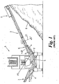
- FIG. 1 a known mobile aggregate processing plant 1 which comprises a chassis 2 upon which a pair of lateral conveyors 3 are mounted.
- the plant comprises a screen (not shown) which distributes the screened material on to the lateral conveyors 3.
- the plant is shown in Figure 1 in an end elevation in order to clearly show the lateral conveyors 3 which are mounted on either side of the chassis 2 of the plant.
- Hydraulic rams 4 are operated to extend the conveyors from a stowed position adjacent the chassis for transport to the operating position shown in Figure 1 .
- the lateral conveyors comprise a tail section 5 adjacent to the chassis 2, a middle section 6 and a head section 7 remote from the chassis 2.
- the head section of the conveyor is mounted to the middle section through a pivot point P1 such that the head section can pivot around the pivot point as shown by axis A in figure 1 .
- Processed material passes along the lateral conveyors from the tail section to the head section and exits the head section to form a stock pile 8 under the head section.
- the middle section of the conveyor is supported against the tail section of the conveyor, which is immobile in relation to the chassis
- the middle section is pivotally connected to the tail section through pivot point P2 such that the middle section can be folded towards the chassis 2 in the direction of Arrow B.
- the lateral conveyors are supported on the chassis of the plant by support means 9 (only one of which is shown in Figure 1 for clarity) which are mounted to the tail section and middle section of the conveyor respectively.
- the tail section of the conveyor is, in turn, firmly mounted to the chassis.
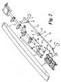
- FIG. 2 shows an exploded view of a lateral conveyor according to one aspect of the present invention.
- the support means 10 for the lateral conveyors of the present invention is in the form of a mounting arm 11a, 11b formed of a box section of mild steel. This may be extruded or cast to the appropriate lengths as required or may be a hollow section if preferred.
- a lateral flange 12 is provided adjacent one end 13 of the mounting arm 11a.
- Triangular support brackets 14 are formed under the flange 12 between the underside of the flange and the mounting arm 11a
- the other end of the mounting arm, remote from the flange 12 is mounted to a C-shaped bracket 15 through a rotational mounting shaft 16 shown in more detail in Figure 3 .
- the C-shaped bracket has a substantially flat top face 17 and a substantially flat bottom face 18 and a back plate 19 extending between the two.
- the top face and bottom face of the bracket are provided with apertures 20 which are aligned on a common axis of the bracket.
- the rotational mounting shaft 16 passes through corresponding aperture (not shown) in the back plate 19 of the bracket and the end face 21 of the mounting arm such that the mounting arm can rotate around its longitudinal axis upon the rotational mounting shaft.
- a bearing (not shown) may be provided between the end face 21 of the mounting arm and the back plate 19 of the bracket in order to facilitate rotation of the mounting arm.
- the means for attaching the mounting arm 11a to the conveyor is shown in detail in Figure 3 .
- a swivel mounting shaft 22 is provided to facilitate traversing of the mounting means around axis F in Figure 2 and comprising a cylindrical shaft member 23 which is attached to the conveyor's head section at one end and is provided with a head section 24 at the distal end, the head section having a greater diameter than the shaft.
- the head section 24 of the cylindrical shaft member is dimensioned to be mounted between the top and bottom faces 17, 18 of the C-shaped bracket 15 and is provided with a through bore 25 which is aligned with the apertures 20 in the top and bottom faces of the bracket when the head section 24 is presented to the bracket.
- a pivot mounting shaft 26 extends through the apertures 20 and the through bore 25 to retain the head section 24 of the swivel mounting means within the bracket 15.
- the pivot mounting shaft 26 facilitates elevation of the mounting arm 11a around axis E shown in Figure 2 by allowing the bracket 15 to pivot around the shaft 26.
- Bearings may be provided between the head section 24 of the swivel mounting shaft 22 and the top and bottom faces 17, 18 of the bracket.
- the articulated joint between the head section 7 and the mounting arm 11a provides three degrees of freedom.
- Figure 4 shows a schematic view of the connection of the mounting arm 11b to the tail section 5 of the conveyor.
- the distal end of the lower section 11b of the mounting arm is provided with an articulated joint having at least two degrees of freedom.
- the lower section 11b of the mounting arm is mounted to the chassis through the swivel mounting shaft 22b of the lower articulated joint which is similar to the joint connecting the upper section of the mounting arm 11a to the head section 7.
- Mounting arm 11b can rotate with the swivel mounting shaft 22b around axis G shown in Figure 2 and can pivot about the pivot mounting shaft 26b around axis H shown in Figure 2 .
- a further rotational mounting shaft may be provided between the end of the mounting arm 11b and the C-shaped bracket 15b to allow for a further rotation of the mounting arm 11b with respect to the bracket 15b. This would provide the joint between the tail section and the mounting arm 11b with a third degree of freedom, which is acceptable but not necessary for carrying out the invention.
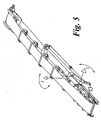
- Hydraulic cylinders 4 are mounted between the tail section 5 and the middle section 6 and the middle section 6 and the head section 7 of the lateral conveyors 3 for extending the conveyors between the operating and the stowed or transit positions.
- a first hydraulic cylinder 4a acts to extend the conveyor out from the chassis around axis I shown in Figure 5
- a second hydraulic cylinder 4b is used to fold the head section of the conveyor back towards the chassis around axis J shown in Figure 5 during transfer from the operating to the transit position as will be described in more detail below.
- a collar 27 is provided between the free ends of the mounting arms 11a and 11b as shown in detail in Figure 6 .
- the collar is provided with apertures (not shown) which align with apertures 27' in the mounting 11b, one of which is shown in Figure 2 .
- a pin 28 is provided through the apertures in the collar and the mounting arm 11b.
- the collar is provided with a lateral flange 29 of similar dimensions to the lateral flange 12 of the upper mounting arm section 11a and is also provided with triangular brackets 30 similar to the brackets 14 described above.
- the flange 29 is provided with threaded aperture (not shown) to receive a locking member 31 which is held in position by a threaded nut 32 or other suitable locking means.
- the collar surrounds the free end of mounting arm section 11b and is fixed thereto with pin 28. The free end of mounting arm section 11a rests on the collar as a result of gravity.
- the lateral conveyors are supported on the chassis in an extended position.
- the threaded nut 32 is loosened and the locking bolt 31 is turned either to increase or to decrease the distance between the flanges 12 and 29 in order to provide fine adjustment of the length of the arm. It is an advantage of the present invention that adjustment of the tracking of the belt can occur during use of the conveyor 3 from a position remote from the head section of the conveyor as this does not require the head section of the conveyor to be lowered to the ground nor are personnel required to stand in the vicinity of the stock pile 8 under the head section 7 of the conveyor where injuries could occur from falling material or close to the running belt, which always creates a hazard of drawing-in.
- the lateral conveyors 3 are moved from the operating position when they extend outboard of the chassis to a stored or transit position inboard of the chassis.
- Nut 32 and the locking bolt 31 are loosened and stopper pin 28 is removed from the apertures in the collar to allow the lower section of the mounting arm 11b to be telescopically received within the upper section of the mounting arm 11a.
- Hydraulic valves (not shown) are opened to operate the first hydraulic cylinder 4a to fold up the middle section of the conveyor 3 and the second hydraulic cylinder 4b to fold the head section 7 of the conveyor sidewards.
- the mounting arm 11 pivots around the pivot mounting shaft.
- the mounting arm swivels on the swivel mounting shaft.
- the length of the mounting arm telescopically alters and the collar and pin are used to lock the length of the mounting arm at the desired length.
- the C-shaped member rotates on the rotational mounting shaft with respect to the mounting arm.
- the conveyor may be extended through the first plane and then traversed through the second plane, or this order can be reversed, or alternatively, both movements may occur simultaneously.
- the conveyor Once the conveyor is in the transport position, it may be locked in this position by replacement of the pin 28.
- the head section can be folded down without moving the conveyor into the transport position.
- the head section may be locked in the service position by replacement of the stopper pin as described above.
- a variable length support means having an articulated joint with 3 degrees of movement in one end and at least 2 degrees of movement in the other end as described above allows for a longer mounting arm to be used than was possible with prior art conveyors as the longer mounting arm of the present invention can still be accommodated within the dimensions of the chassis of the plant when the conveyor is in the transport position.
- a longer mounting arm can be used, therefore a longer conveyor can be supported upon the chassis of the plant.
- Use of a longer conveyor enables a greater capacity of material to be processed during operation of the plant.
- the load on the conveyor is spread along a greater length of the conveyor frame and provides a more stable plant than was previously available which is not as susceptible to unfavorable working conditions such as soft or uneven ground of the worksite causing extensive vibration.
- the tracking of the belt of the conveyor can be adjusted during operation. This is a significant advantage over prior art conveyors where the tracking is adjusted by altering the position of the belt on rollers within the head section of the conveyor which has to be done by lowering the head section to ground level. Such an operation could only take place during an interruption of the processing operation.
- the lateral conveyor has been described above as having three sections, a tail section, a middle section and a head section, it is envisaged that the head section of the conveyor can also be divided into separate subsections pivotable with respect to each other.
- the embodiment provides a joint between mounting arm 11a and the head section 7 of the conveyor with three degrees of freedom and a joint between mounting arm 11b and the tail section 5 of the conveyor with two degrees of freedom.
- these two types of joints can replace each other. Also both joints can provide three degrees of freedom.
- the embodiment provides a support extending between the head section 7 of the conveyor and the tail section 5 of the conveyor.
- hydraulic cylinder driving means other driving means may be used for example, hydraulic motors, pneumatic cylinders, pneumatic motors or electric motors with the necessary power transmission means. These driving means are preferably double acting for forward and backward movement.
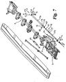
- Figures 7 to 9 provide schematic views of a lateral conveyor according to another embodiment of the present invention. Most of the components of the embodiment of Figures 7 to 9 are the same as those of the embodiment of Figures 2 to 4 and thus reference should be made to the description given above with reference to Figures 2 to 4 . Here, differences between the embodiment of Figures 2 to 4 and the embodiment of Figures 2 to 4 will be described.
- Figure 7 provides an exploded view of the lateral conveyor according to the other embodiment.
- This embodiment provides for two degrees of freedom of movement in the connection of the mounting arm 11a to the head section 7 of the conveyor instead of the three degrees of freedom of movement of the previous embodiment.
- the two degrees of freedom of movement are: elevation of the mounting arm 11a around axis E by allowing the bracket 15 to pivot around the shaft 26; and traversing of the mounting means around axis F by means of the swivel mounting shaft 22.
- Figure 8 provides an enlarged schematic side view of the end of mounting arm 11a shown in Figure 7 . It is not required of this embodiment that the mounting arm 11a rotates around axis D. However, this embodiment may also be configured in the same way as the previous embodiment for rotation of the mounting arm 11a around axis D.
- mounting arm 11b is connected to the tail section 5 of the conveyer in the same way as the previous embodiment.
- the connection of Figure 9 provides for two degrees of freedom of movement in common with the previous embodiment.
- a further rotational mounting shaft may be provided between the end of the mounting arm 11b and the C-shaped bracket 15b to allow for a further rotation of the mounting arm 11b with respect to the bracket 15b. This provides the joint between the tail section and the mounting arm 11b with a third degree of freedom, which is acceptable but not necessary for carrying out the invention.
- a collar 40 is provided between the free ends of the mounting arms 11a and 11b.
- One of the two mounting arms 11a and 11b is received in the other and provides for telescopic variation of the length of the support means 10.
- the co-locating ends 13 and 41 of the two mounting arms 11a and 11b are of substantially circular cross-section, the two mounting arms 11a and 11b are rotatable in relation to each other about axis D.
- the collar 40 is configured to cooperate with the circular cross sections of the ends of the two mounting arms 11a and 11b. This means that in this embodiment, two degrees of freedom of movement are provided by the connection between mounting arms 11a and 11b, whereas in the previous embodiment there is only one degree of freedom of movement, namely relative linear movement of the two mounting arms 11a and 11b.
- connection between the mounting arm 11a and the head section 7 provides for two degrees of freedom of movement and the connection between the two mounting arms 11a and 11b provides for two degrees of freedom of movement.
- connection between the mounting arm 11a and the head section 7 provides for three degrees of freedom of movement and the connection between the two mounting arms 11a and 11b provides for one degree of freedom of movement.
- the support means of this invention finds use in the aggregate material processing industry.
Landscapes
- Engineering & Computer Science (AREA)
- Mechanical Engineering (AREA)
- Framework For Endless Conveyors (AREA)
Abstract
Description
- This invention relates to improvements in support means for supporting a lateral conveyor particularly adapted for mounting on a mobile, aggregate material processing plant such as screening plant, crushing plant or mining plant, and, more particularly, to improvements in the support arms for supporting a stowable lateral conveyor upon the plant.
- In this specification, the term "aggregate material" means different types of mined or quarried or natural mineral materials, like gravel, sand, ores, coal, different kinds of soil materials like loam and peat, different kinds of construction waste materials like concrete, bricks and asphalt as well as organic materials like timber wood chips, etc.
- In this specification, the term "processing" of aggregate materials means feeding, shredding, crushing, screening, separating, washing and conveying of aggregate materials.
- In aggregate material processing plant generally, processing capacity is heavily influenced by the ability to quickly and effectively deliver the processed material away from the plant. To achieve this, it is known to provide lateral conveyors which extend transversely of the plant, possibly in addition to longitudinal conveyors. While the manner in which the lateral conveyors are connected to the plant is relatively simple for the operating position, major problems arise in ensuring that the overall width and height of the mobile plant is within certain dimensions when carrying such conveyors during transport. Another problem is ensuring safety, on-site, in movement of the lateral conveyors to a position for transport of the mobile plant. A further problem lies in the support of the lateral conveyors during operation and when travelling inside the worksite with the conveyors in the working position: the conveyors are subject to high stresses due to their own weight, the weight of the screened material on the belt and vibrations caused by uneven and/or soft soil at the worksite. A still further problem is that of providing for easy and safe maintenance or repair of the lateral conveyors on-site or at a workshop.
-
EP 0641 607B describes a known mobile aggregate material processing plant comprising a chassis having a pair of longitudinal beams mounted on wheels and supported on jack legs. - The plant is provided with two lateral conveyors each of which comprises a tail section, a middle section and a head section. The head section delivers processed material to form a stockpile of material. The conveyors are folded from the working position to the transport position by a pair of hydraulic rams. In the working position the conveyor is supported on the chassis by a support extending between the middle section and the tail section of the conveyor, the tail section being fixed to the chassis of the mobile plant. The head section of the conveyor is left unsupported.
- The amount of material which can be processed by the plant is determined in part by the length of the lateral conveyors. The longer the conveyors are the higher and bigger in volume the stockpiles can be and the less you have to reserve resources for transferring the material away from the machine's stockpiles. In some instances, only one feeding machine, e.g. a wheel loader, is used for both feeding the machine and removing the processed material from the stockpiles. The bigger the stockpiles are the more freedom for planning the feeding/removing work and the less unplanned breaks have to be included in the job.
- The dimensions of the conveyors in the transport position are limited by the permissible transport dimensions of the machine, as regulated in the road transport regulations. Neither the conveyors nor their supports, nor any other part of the plant is allowed to exceed these dimensions. If, for example, the chassis is dimensioned to be exactly within the permissible transport width, then the conveyors and their supports must not project laterally beyond the chassis.
-
EP 0641 607B provides a good solution for folding the lateral conveyors from a working position to transport position making it possible firstly to fold the middle section around the first axis being substantially parallel to the longitudinal axis of the chassis of the plant and secondly to fold the head section around the second axis substantially parallel to the lateral axis of the chassis of the plant, and back. So far, it has been a problem, to easily and effectively support such foldable conveyors. - In
EP 0641 607B the path of the head section of the conveyor from the working position to the transport position is relatively complicated. So far it has not been possible to provide foldable support beams for the head section, which is easy to use and does not challenge the permissible transport dimensions of the plant. The manufacturers have had to settle with a foldable support beam extending between the middle section and the tail section of the conveyor, as the path of middle section from the working position to the transport position is much simpler than that of the head section. Anyhow, this sort of support leaves the head section unsupported, which makes the conveyors subject to high stresses due to their own weight, the weight of the screened material on the belt and vibrations caused by uneven and/or soft soil at the worksite while working or travelling inside the worksite with the conveyors in the working position. - Manufacturers and users of such plants have tried to solve the problem by extending the length of the middle section of the conveyor to provide a better support with foldable support beams. However, this would challenge the transportation height of the plant. Also detachable, non-foldable, supports between the conveyor's head section and the plant chassis and/or the ground have been used: these have proved to be difficult to use or even dangerous in situations where the support has detached itself accidentally.
- In
US 3684255 there is disclosed a continuous conveyor of a foldable type mounted on a wheeled frame, preferably of a self-propelled vehicle, together with the means for driving the conveyor and to vary the relative positions of the parts forming the conveyor from its inoperative position in which it is folded to occupy the most reduced space, to any desired working position. The conveyor is preferably associated with a concrete mixer truck and is constituted of at least two rectangular frame sections pivotally interconnected and supported by a bracket to freely projecting outwards. The conveyor rotates around a vertical axis to be moved from its retracted arrangement in which it is folded along a lateral side of the vehicle, to an arrangement in which its charging end is positioned in the longitudinal vertical center plane of the vehicle and just below the discharge opening of the mixer of the truck. - A still further problem is that of providing for easy and safe maintenance or repair of the lateral conveyors on-site or at a workshop. Head sections often include some parts requiring maintenance, like motor, bearings, belt scraper, safeguarding etc. A safe way of reaching these parts has proved illusive as they are quite high and ground in the worksite is usually soft or uneven, which makes it dangerous to work using ladders. More safe equipment helping the service people to reach high is not often available in the worksites.
- It is an object of the present invention to provide a mobile aggregate processing plant which can support lateral conveyors of a greater length than is currently possible with known plant, such as described above in relation to
EP 0641607B . - Additionally, it is a further object of the present invention to provide a safe and easy to use support means for a lateral conveyor of an aggregate processing plant which allows the lateral conveyor to be stowed in a transit position within permissible dimensions.
- Further, it is an added object of the present invention to provide a support means for a lateral conveyor or an aggregate processing plant which allows the head section of the lateral conveyor to be accessed from the ground for easy maintenance and repair thereof.
- According to a first aspect of the present invention, there is provided a lateral conveyor adapted for mounting upon a mobile chassis as claimed in claim 1.
- Other optional features of the invention are as provided in the appended claims.
- Embodiments of the present invention will now be described, by way of example only, with reference to and as shown in the accompanying drawings in which:
-
Figure 1 is a schematic view of a known processing plant according to the prior art which illustrates a known support means for a lateral conveyor mounted on the chassis of the plant; -
Figure 2 is an exploded view of a lateral conveyor according to an embodiment of the present invention; -
Figure 3 is an enlarged schematic side view of one end of the section of the mounting arm shown inFigure 2 ; -
Figure 4 is an enlarged schematic side view of the other end of the mounting arm ofFigure 2 ; -
Figure 5 is schematic view of the conveyor and support ofFigure 2 showing the folding axis of the conveyor, -
Figure 6 is a schematic view of the collar locking the length of the mounting arm and the adjustment means provided thereon, and -
Figure 7 is an exploded view of a lateral conveyor according to another embodiment of the present invention; -
Figure 8 is an enlarged schematic side view of one end of the section of the mounting arm shown inFigure 7 ; and -
Figure 9 is an enlarged schematic side view of the other end of the mounting arm ofFigure 7 . - Turning now to the Figures, there is shown in
Figure 1 a known mobile aggregate processing plant 1 which comprises a chassis 2 upon which a pair oflateral conveyors 3 are mounted. The plant comprises a screen (not shown) which distributes the screened material on to thelateral conveyors 3. The plant is shown inFigure 1 in an end elevation in order to clearly show thelateral conveyors 3 which are mounted on either side of the chassis 2 of the plant. - Hydraulic rams 4 are operated to extend the conveyors from a stowed position adjacent the chassis for transport to the operating position shown in
Figure 1 . The lateral conveyors comprise atail section 5 adjacent to the chassis 2, amiddle section 6 and ahead section 7 remote from the chassis 2. The head section of the conveyor is mounted to the middle section through a pivot point P1 such that the head section can pivot around the pivot point as shown by axis A infigure 1 . Processed material passes along the lateral conveyors from the tail section to the head section and exits the head section to form astock pile 8 under the head section. The middle section of the conveyor is supported against the tail section of the conveyor, which is immobile in relation to the chassis The middle section is pivotally connected to the tail section through pivot point P2 such that the middle section can be folded towards the chassis 2 in the direction of Arrow B. - The lateral conveyors are supported on the chassis of the plant by support means 9 (only one of which is shown in
Figure 1 for clarity) which are mounted to the tail section and middle section of the conveyor respectively. The tail section of the conveyor is, in turn, firmly mounted to the chassis. -
Figure 2 shows an exploded view of a lateral conveyor according to one aspect of the present invention. The support means 10 for the lateral conveyors of the present invention is in the form of a mountingarm lateral flange 12 is provided adjacent oneend 13 of the mountingarm 11a.Triangular support brackets 14 are formed under theflange 12 between the underside of the flange and the mountingarm 11a - The other end of the mounting arm, remote from the
flange 12 is mounted to a C-shapedbracket 15 through a rotational mountingshaft 16 shown in more detail inFigure 3 . This allows the mountingarm 11a to rotate around axis D shown inFigure 2 with respect to thebracket 15. The C-shaped bracket has a substantially flattop face 17 and a substantially flatbottom face 18 and aback plate 19 extending between the two. The top face and bottom face of the bracket are provided withapertures 20 which are aligned on a common axis of the bracket. - The rotational mounting
shaft 16 passes through corresponding aperture (not shown) in theback plate 19 of the bracket and theend face 21 of the mounting arm such that the mounting arm can rotate around its longitudinal axis upon the rotational mounting shaft. A bearing (not shown) may be provided between theend face 21 of the mounting arm and theback plate 19 of the bracket in order to facilitate rotation of the mounting arm. - The means for attaching the mounting
arm 11a to the conveyor is shown in detail inFigure 3 . This shows the end of the mountingarm 11a with the C-shapedbracket 15 attached thereto. Aswivel mounting shaft 22 is provided to facilitate traversing of the mounting means around axis F inFigure 2 and comprising acylindrical shaft member 23 which is attached to the conveyor's head section at one end and is provided with ahead section 24 at the distal end, the head section having a greater diameter than the shaft. - The
head section 24 of the cylindrical shaft member is dimensioned to be mounted between the top and bottom faces 17, 18 of the C-shapedbracket 15 and is provided with a throughbore 25 which is aligned with theapertures 20 in the top and bottom faces of the bracket when thehead section 24 is presented to the bracket. - A
pivot mounting shaft 26 extends through theapertures 20 and the through bore 25 to retain thehead section 24 of the swivel mounting means within thebracket 15. Thepivot mounting shaft 26 facilitates elevation of the mountingarm 11a around axis E shown inFigure 2 by allowing thebracket 15 to pivot around theshaft 26. Bearings (not shown) may be provided between thehead section 24 of theswivel mounting shaft 22 and the top and bottom faces 17, 18 of the bracket. - The articulated joint between the
head section 7 and the mountingarm 11a, as described above, provides three degrees of freedom. -
Figure 4 shows a schematic view of the connection of the mountingarm 11b to thetail section 5 of the conveyor. The distal end of thelower section 11b of the mounting arm is provided with an articulated joint having at least two degrees of freedom. Thelower section 11b of the mounting arm is mounted to the chassis through theswivel mounting shaft 22b of the lower articulated joint which is similar to the joint connecting the upper section of the mountingarm 11a to thehead section 7. Mountingarm 11b can rotate with theswivel mounting shaft 22b around axis G shown inFigure 2 and can pivot about thepivot mounting shaft 26b around axis H shown inFigure 2 . - A further rotational mounting shaft may be provided between the end of the mounting
arm 11b and the C-shapedbracket 15b to allow for a further rotation of the mountingarm 11b with respect to thebracket 15b. This would provide the joint between the tail section and the mountingarm 11b with a third degree of freedom, which is acceptable but not necessary for carrying out the invention. - Hydraulic cylinders 4 are mounted between the
tail section 5 and themiddle section 6 and themiddle section 6 and thehead section 7 of thelateral conveyors 3 for extending the conveyors between the operating and the stowed or transit positions. A first hydraulic cylinder 4a acts to extend the conveyor out from the chassis around axis I shown inFigure 5 , and a second hydraulic cylinder 4b is used to fold the head section of the conveyor back towards the chassis around axis J shown inFigure 5 during transfer from the operating to the transit position as will be described in more detail below. - A
collar 27 is provided between the free ends of the mountingarms Figure 6 . The collar is provided with apertures (not shown) which align with apertures 27' in the mounting 11b, one of which is shown inFigure 2 . - A
pin 28 is provided through the apertures in the collar and the mountingarm 11b. The collar is provided with alateral flange 29 of similar dimensions to thelateral flange 12 of the upper mountingarm section 11a and is also provided withtriangular brackets 30 similar to thebrackets 14 described above. Theflange 29 is provided with threaded aperture (not shown) to receive a lockingmember 31 which is held in position by a threadednut 32 or other suitable locking means. The collar surrounds the free end of mountingarm section 11b and is fixed thereto withpin 28. The free end of mountingarm section 11a rests on the collar as a result of gravity. - In use of the plant, during operation the lateral conveyors are supported on the chassis in an extended position. In the event that the tracking of the belt upon the conveyor requires adjustment during use, the threaded
nut 32 is loosened and the lockingbolt 31 is turned either to increase or to decrease the distance between theflanges conveyor 3 from a position remote from the head section of the conveyor as this does not require the head section of the conveyor to be lowered to the ground nor are personnel required to stand in the vicinity of thestock pile 8 under thehead section 7 of the conveyor where injuries could occur from falling material or close to the running belt, which always creates a hazard of drawing-in. - When operation of the plant is completed and the chassis 2 is to be moved to a new location, the
lateral conveyors 3 are moved from the operating position when they extend outboard of the chassis to a stored or transit position inboard of the chassis.Nut 32 and the lockingbolt 31 are loosened andstopper pin 28 is removed from the apertures in the collar to allow the lower section of the mountingarm 11b to be telescopically received within the upper section of the mountingarm 11a. Hydraulic valves (not shown) are opened to operate the first hydraulic cylinder 4a to fold up the middle section of theconveyor 3 and the second hydraulic cylinder 4b to fold thehead section 7 of the conveyor sidewards. - As the conveyor is lowered towards the ground the mounting arm 11 pivots around the pivot mounting shaft. As the head section is folded towards the middle of the conveyor, the mounting arm swivels on the swivel mounting shaft. During this operation, the length of the mounting arm telescopically alters and the collar and pin are used to lock the length of the mounting arm at the desired length. Furthermore, during this operation, the C-shaped member rotates on the rotational mounting shaft with respect to the mounting arm.
- The conveyor may be extended through the first plane and then traversed through the second plane, or this order can be reversed, or alternatively, both movements may occur simultaneously.
- Once the conveyor is in the transport position, it may be locked in this position by replacement of the
pin 28. In the event that service or maintenance of the head section is required, the head section can be folded down without moving the conveyor into the transport position. As with the transport position, the head section may be locked in the service position by replacement of the stopper pin as described above. - A variable length support means having an articulated joint with 3 degrees of movement in one end and at least 2 degrees of movement in the other end as described above allows for a longer mounting arm to be used than was possible with prior art conveyors as the longer mounting arm of the present invention can still be accommodated within the dimensions of the chassis of the plant when the conveyor is in the transport position. As a longer mounting arm can be used, therefore a longer conveyor can be supported upon the chassis of the plant. Use of a longer conveyor enables a greater capacity of material to be processed during operation of the plant. Furthermore, the load on the conveyor is spread along a greater length of the conveyor frame and provides a more stable plant than was previously available which is not as susceptible to unfavorable working conditions such as soft or uneven ground of the worksite causing extensive vibration.
- As described above, the tracking of the belt of the conveyor can be adjusted during operation. This is a significant advantage over prior art conveyors where the tracking is adjusted by altering the position of the belt on rollers within the head section of the conveyor which has to be done by lowering the head section to ground level. Such an operation could only take place during an interruption of the processing operation.
- Whilst the present invention has been described as having a support member in the form of a mounting arm, it is envisaged that two such mounting arms will preferably be provided on the chassis to support a lateral conveyor.
- Although the lateral conveyor has been described above as having three sections, a tail section, a middle section and a head section, it is envisaged that the head section of the conveyor can also be divided into separate subsections pivotable with respect to each other.
- The embodiment provides a joint between mounting
arm 11a and thehead section 7 of the conveyor with three degrees of freedom and a joint between mountingarm 11b and thetail section 5 of the conveyor with two degrees of freedom. Within the scope of the claims, these two types of joints can replace each other. Also both joints can provide three degrees of freedom. - The embodiment provides a support extending between the
head section 7 of the conveyor and thetail section 5 of the conveyor. - In addition, instead of hydraulic cylinder driving means other driving means may be used for example, hydraulic motors, pneumatic cylinders, pneumatic motors or electric motors with the necessary power transmission means. These driving means are preferably double acting for forward and backward movement.
-
Figures 7 to 9 provide schematic views of a lateral conveyor according to another embodiment of the present invention. Most of the components of the embodiment ofFigures 7 to 9 are the same as those of the embodiment ofFigures 2 to 4 and thus reference should be made to the description given above with reference toFigures 2 to 4 . Here, differences between the embodiment ofFigures 2 to 4 and the embodiment ofFigures 2 to 4 will be described. -
Figure 7 provides an exploded view of the lateral conveyor according to the other embodiment. This embodiment provides for two degrees of freedom of movement in the connection of the mountingarm 11a to thehead section 7 of the conveyor instead of the three degrees of freedom of movement of the previous embodiment. The two degrees of freedom of movement are: elevation of the mountingarm 11a around axis E by allowing thebracket 15 to pivot around theshaft 26; and traversing of the mounting means around axis F by means of theswivel mounting shaft 22.Figure 8 provides an enlarged schematic side view of the end of mountingarm 11a shown inFigure 7 . It is not required of this embodiment that the mountingarm 11a rotates around axis D. However, this embodiment may also be configured in the same way as the previous embodiment for rotation of the mountingarm 11a around axis D. - Turning to
Figure 9 , it can be seen that mountingarm 11b is connected to thetail section 5 of the conveyer in the same way as the previous embodiment. The connection ofFigure 9 provides for two degrees of freedom of movement in common with the previous embodiment. In addition and in common with the previous embodiment, a further rotational mounting shaft may be provided between the end of the mountingarm 11b and the C-shapedbracket 15b to allow for a further rotation of the mountingarm 11b with respect to thebracket 15b. This provides the joint between the tail section and the mountingarm 11b with a third degree of freedom, which is acceptable but not necessary for carrying out the invention. - Returning now to
Figure 7 , acollar 40 is provided between the free ends of the mountingarms collar 40 of this embodiment is different from the form of thecollar 27 of the previous embodiment as described below, reference should be made toFigure 6 for a description of the corresponding component parts of thecollar 40. One of the two mountingarms arms arms collar 40 is configured to cooperate with the circular cross sections of the ends of the two mountingarms arms arms - Operation of the invention in accordance with this embodiment is the same as operation in accordance with the previous embodiment. Thus, the reader is referred to the description given above in relation to the operation of the previous embodiment.
- In summary, in this embodiment the connection between the mounting
arm 11a and thehead section 7 provides for two degrees of freedom of movement and the connection between the two mountingarms arm 11a and thehead section 7 provides for three degrees of freedom of movement and the connection between the two mountingarms - The support means of this invention finds use in the aggregate material processing industry.
Claims (26)
- A lateral conveyor adapted for mounting upon a mobile-chassis and movable between a working-position, where the lateral conveyor extends outboard of the chassis, and a transit position; comprising,a) a tail section (5) for mounting to the mobile chassis,b) a middle section (6),c) at least one head section (7),d) a support means (10) comprising a mounting arm having a first and a second end, wherein said mounting arm comprises a first section (11a) and a second section (11b), one of the two sections (11a,11b) being configured for sliding in relation to the other so as to vary the length of the mounting arm, said support means (10) comprising, furthermore means (27,40) for locking the length of the mounting arm into at least one fixed length corresponding to the length of the conveyor in the working position,e) wherein said middle section (6) is pivotable in relation to said tail section (5) around a first axis (I) substantially parallel to a lateral axis of the middle section (6),f) wherein said head section (7) is pivotable in relation to said middle section (6) around a second axis (J) substantially perpendicular to a longitudinal axis and to a lateral axis of the middle section (6),g) wherein the first end of the mounting arm is provided with means to fix said mounting arm to said mobile chassis or a part fixed immobile in relation to said mobile chassis,h) wherein the second end of the mounting arm is fixed to the said head section or a part fixed immobile in relation to the said head section (7) of the conveyor,i) wherein first kinematic pair is formed by the first section (11a) of the mounting arm and the mobile chassis and is provided by a first joint,j) a second kinematic pair is formed by the first and second sections (11a, 11b) of the mounting arm,k) a third kinematic pair is formed by the second section (11b) of the mounting arm and the head section (7) of the conveyors and is provided by a second joint,l) wherein the first kinematic pair provides for two or three rotational degrees of freedom of movement, and the third kinematic pair provides for two or three rotational degrees of freedom of movement,
and wherein:at least one of said first kinematic pair or said third kinematic pair provides for three rotational degrees or freedom of movement and/or said second kinematic pair provides for said first and second sections being configured for rotation in relation to each other about their longitudinal axis (D). - The lateral conveyor according to claim 1, in which the first and second joints are configured such that the first kinematic pair provides for three rotational degrees of freedom of movement and the third kinematic pair provides for two rotational degrees of freedom of movement.
- The lateral conveyor according to claim 1, in which the first and second joints are configured such that the first kinematic pair provides for two rotational degrees of freedom of movement and the third kinematic pair provides for three rotational degrees of freedom of movement.
- The lateral conveyor according to claim 1, in which the first and second joints are configured such that both the first and third kinematic pairs provide for three rotational degrees of freedom of movement.
- The lateral conveyor according to claim 1 2, or 3,
in which providing , the two rotational degrees of freedom of movement of the first kinematic pair providing and/or of the third kinematic pair
said first joint and/or said second joint, as appropriate, comprises a pivot mounting shaft (26b) and
a swivel mounting shaft (22b), whereby the mounting arm
may be elevated in a one plane by pivoting upon the pivot mounting shaft and traversed in another plane by swivelling on the swivel mounting shaft. - The lateral conveyor according to any of the preceding claims 1-4, in which providing the three rotational degrees of freedom of movement of the first kinematic pair and/or of the third kinematic pair
, as appropriate, comprises a pivot mounting shaft (26), a swivel mounting shaft (22), and a rotational mounting shaft (16), whereby the mounting arm may be elevated in a first plane by pivoting upon the pivot mounting shaft (26) and traversed in a second plane by swivelling on the swivel mounting shaft (22), and rotated about its longitudinal axis (D,G) on the rotational mounting shaft (16). - The lateral conveyor according to claim 6, in which the first and second planes are perpendicular.
- The lateral conveyor according to claim 7, in which the longitudinal axis of the second section (11b) is substantially parallel to a line of intersection of said plane.
- The lateral conveyor according to any of claims 6 to 8, in which a C-shaped bracket (15) comprising a top face (17), a bottom face (18) and a back plate (19) extending between the top and bottom faces is mounted on at least one end of the mounting arm, through the rotational mounting shaft.
- The lateral conveyor according to claim 9, in which the top and bottom faces of the C-shaped bracket (15) are substantially parallel and the back plate (19) extends substantially perpendicularly to the top and bottom faces (17;18).
- The lateral conveyor according to claim 9 or 10, in which bearing means is provided between an end face of the mounting arm and the back plate (19) of the bracket (15).
- The lateral conveyor according to any of claims 9 to 11, in which an aperture (20) is provided in each of the top and bottom faces (17;18) of the C-shaped bracket (15), said apertures (20) being aligned along a common axis through the bracket (15).
- The lateral conveyor according to claim 12, in which the swivel mounting shaft (22) is provided with a through bore (25) and said swivel mounting shaft (22) is mounted within the C-shaped bracket (15) such that the bore (25) is aligned with the apertures (20) in the top and bottom face (17;18) of the bracket (15).
- The lateral conveyor according to claim 13, in which the pivot mounting shaft (26) extends though the apertures (20) in the top and bottom faces (17;18) of the C-shaped bracket (15) and the bore (25) of the swivel mounting shaft (22) to lock the swivel mounting shaft (22) in position within the bracket (15).
- The lateral conveyor according to any of claims 1 to 14, wherein the first and second sections (11a, 11b) are configured such that one of the two sections is received in the other for telescopic variation of the mounting arm.
- The lateral conveyor according to claim 15, in which the mounting arm comprises a hydraulic cylinder (4a, 4b).
- The lateral conveyor according to claim 15 or 16 wherein the co-locating portions (13, 41) of the first and second sections (11a, 11b) comprise a substantially circular cross-section so that the first and second sections (11a, 11b) are rotatable to each other about their longitudinal axis (D).
- The lateral conveyor according to any preceding claim, in which the mounting arm comprises three sections, arranged such that one of the first and second sections is configured for sliding in relation to the other so as to vary the length of the mounting arm and the second and third sections is configured for rotation in relation to each other about their longitudinal axis.
- The lateral conveyor according to any preceding claim, in which the means (27, 40) for locking the length of the variable length mounting arm is adapted to fix a length corresponding to the length of the conveyor in the transit position and/or working position.
- The lateral conveyor according to any preceding claim, in which the head section (7) of the conveyor consists of at least two separate sections pivotable to each other, the first of the said head sections being supported to said mobile chassis or a part fixed immobile in relation to said mobile chassis with said variable length arm.
- The lateral conveyor according to any preceding claim, in which the means for locking the length of the mounting arm comprises a collar (40) and a locking pin (28) provided to fix the length of the mounting arm to correspond to the working position of the conveyor, preferably also to the transit position and to a maintenance position.
- The lateral conveyor according to any preceding claim, in which bearing means is provided between all gliding surfaces.
- The lateral conveyor according to any preceding claim, in which the support means is formed of mild steel.
- The lateral conveyor according to any preceding claim, wherein adjustment means are provided to finely alter the length of the mounting arm when loked into the at least on fixed length.
- A mobile chassis comprising a lateral conveyor according to any preceding claim mounted thereon.
- The mobile chassis according to claim 25, in which the mobile chassis is a mobile aggregate processing plant.
Priority Applications (1)
| Application Number | Priority Date | Filing Date | Title |
|---|---|---|---|
| PL04730598T PL1628896T3 (en) | 2003-05-02 | 2004-04-30 | Lateral conveyor and mobile chassis comprising such a lateral conveyor |
Applications Claiming Priority (2)
| Application Number | Priority Date | Filing Date | Title |
|---|---|---|---|
| GB0310177 | 2003-05-02 | ||
| PCT/GB2004/001922 WO2004096677A1 (en) | 2003-05-02 | 2004-04-30 | Support means for a lateral conveyor on a mobile chassis |
Publications (2)
| Publication Number | Publication Date |
|---|---|
| EP1628896A1 EP1628896A1 (en) | 2006-03-01 |
| EP1628896B1 true EP1628896B1 (en) | 2012-08-01 |
Family
ID=32408049
Family Applications (1)
| Application Number | Title | Priority Date | Filing Date |
|---|---|---|---|
| EP04730598A Expired - Lifetime EP1628896B1 (en) | 2003-05-02 | 2004-04-30 | Lateral conveyor and mobile chassis comprising such a lateral conveyor |
Country Status (7)
| Country | Link |
|---|---|
| US (1) | US7552818B2 (en) |
| EP (1) | EP1628896B1 (en) |
| JP (1) | JP5021296B2 (en) |
| ES (1) | ES2391045T3 (en) |
| GB (1) | GB2401846B (en) |
| PL (1) | PL1628896T3 (en) |
| WO (1) | WO2004096677A1 (en) |
Cited By (2)
| Publication number | Priority date | Publication date | Assignee | Title |
|---|---|---|---|---|
| WO2016150727A1 (en) | 2015-03-25 | 2016-09-29 | Kleemann Gmbh | Folding mechanism for a conveyor device |
| EP4344785A1 (en) | 2022-09-29 | 2024-04-03 | SBM Mineral Processing GmbH | Processing device |
Families Citing this family (20)
| Publication number | Priority date | Publication date | Assignee | Title |
|---|---|---|---|---|
| US7464889B2 (en) | 2002-06-06 | 2008-12-16 | Johnson Crushers International | Mobile rock crushing plant |
| US6935587B2 (en) | 2002-06-06 | 2005-08-30 | Johnson Crushers International | Mobile rock crushing plant |
| US7264104B2 (en) | 2005-03-11 | 2007-09-04 | Johnson Crushers International | Crusher in-feed conveyor method and apparatus |
| EP1963213B1 (en) * | 2005-12-09 | 2017-02-08 | Metso Minerals, Inc. | Material processing apparatus comprising a conveyor |
| CN101384378A (en) * | 2006-02-16 | 2009-03-11 | 奥贾伊研究与设计有限公司 | A material screening apparatus |
| US8573387B2 (en) * | 2007-03-07 | 2013-11-05 | David Trimble | Foldable framework for auxiliary conveyor |
| US7891479B2 (en) | 2007-09-07 | 2011-02-22 | Carl Evangelista | Modular conveyor system |
| US20100008750A1 (en) * | 2008-07-08 | 2010-01-14 | Dan Jones, Inc. | Trailers,systems and methods for transferring material |
| US7708131B2 (en) * | 2008-09-02 | 2010-05-04 | Gordon Muth | Swing auger hopper drive |
| US7997406B2 (en) * | 2009-05-14 | 2011-08-16 | Flsmidth A/S | Conveyor apparatus |
| US8876216B2 (en) | 2010-02-26 | 2014-11-04 | All Right Steel, Llc | Dump trailer |
| WO2011106662A1 (en) | 2010-02-26 | 2011-09-01 | Stewart Larry T | Dump trailer |
| GB2507767A (en) * | 2012-11-08 | 2014-05-14 | Terex Gb Ltd | Conveyor adjustable input support frame |
| US9376260B2 (en) * | 2014-02-06 | 2016-06-28 | Metso Minerals, Inc. | Conveyor body and mobile mineral material processing plant |
| DE102015003239A1 (en) * | 2015-03-10 | 2016-09-15 | Beumer Gmbh & Co. Kg | Device for loading or unloading a transport container |
| US9549505B1 (en) * | 2015-09-21 | 2017-01-24 | Deere & Company | Agricultural vehicle conveyance linkage |
| CN108945982A (en) * | 2018-08-03 | 2018-12-07 | 四川高通环保科技股份有限公司 | Categorized consumer waste handles belt conveyor |
| US10781864B2 (en) | 2018-11-16 | 2020-09-22 | Glg Farms Llc | Drive wheel clutch system |
| CN110817338A (en) * | 2019-12-05 | 2020-02-21 | 华电重工股份有限公司 | Flexible frame and belt conveyor for material conveyor |
| FI130584B (en) * | 2022-01-31 | 2023-11-23 | Metso Finland Oy | Conveyor system of a mobile mineral material processing plant |
Family Cites Families (24)
| Publication number | Priority date | Publication date | Assignee | Title |
|---|---|---|---|---|
| CA926382A (en) * | 1970-01-15 | 1973-05-15 | Rossi Lionello | Articulated pivotable continuous conveyor mounted on a wheeled frame, preferably carrying also a rotating mixer |
| US3768784A (en) * | 1971-12-16 | 1973-10-30 | Symons Corp | Distributing conveyor system for a rotary concrete mixing or other truck |
| JPS5416458Y2 (en) * | 1975-06-18 | 1979-06-28 | ||
| JPS5820572Y2 (en) * | 1979-09-30 | 1983-04-28 | ナショナル住宅産業株式会社 | Conveyance device |
| CA1191487A (en) * | 1981-11-06 | 1985-08-06 | Richard Crawshay | Continuous loading apparatus and method |
| JPS58161917U (en) * | 1982-04-23 | 1983-10-28 | ナショナル住宅産業株式会社 | Orthogonal conveyance device that doubles as a workbench |
| US4579479A (en) * | 1984-04-26 | 1986-04-01 | Bryant Joseph H | Pothole patching and roadway surface paving machine |
| US4780041A (en) * | 1987-08-03 | 1988-10-25 | Ashby Jr Charles W | Extendable conveyor system |
| US5333725A (en) * | 1989-12-22 | 1994-08-02 | Douglas Patrick J | Foldable framework for belt conveyor |
| US5123519A (en) * | 1991-02-12 | 1992-06-23 | Edw. C. Levy Company | Knuckled hydraulically-actuated stacking coveyor |
| US5184715A (en) * | 1991-05-09 | 1993-02-09 | Core Industries, Inc. | Mechanical drive for dual conveyor system |
| US5178253A (en) * | 1991-08-26 | 1993-01-12 | Ingersoll-Rand Company | Swing mechanism for a vehicular conveyor |
| US5348130A (en) * | 1993-07-30 | 1994-09-20 | Joy Mm Delaware, Inc. | Advanceable auxiliary conveying apparatus |
| GB2282361B (en) * | 1993-09-07 | 1997-01-08 | Malachy James Rafferty | A mobile aggregate material processing plant |
| US5562194A (en) * | 1995-03-06 | 1996-10-08 | Krupp Fordertechnik Gmbh | Conveyor-displacing system and method for mining operation |
| US5779321A (en) * | 1996-11-12 | 1998-07-14 | Arch Technology Corporation | Swing tail assembly for miner |
| US6360873B1 (en) * | 1997-09-19 | 2002-03-26 | The Mead Corporation | Article grouping mechanism |
| US6283269B1 (en) * | 1999-12-03 | 2001-09-04 | Putzmeister, Inc. | Vehicle-mounted extendable conveyor having variable angle infeed conveyor assembly |
| US6296109B1 (en) * | 2000-02-02 | 2001-10-02 | Astec Industries Inc. | Fold linkage and method of using same |
| US6698594B2 (en) * | 2002-03-18 | 2004-03-02 | Ohio Central Steel Company | Screening machine |
| DE20101395U1 (en) * | 2001-01-26 | 2001-04-26 | Joseph Voegele Ag, 68163 Mannheim | Feeder and assembly device |
| US7273150B2 (en) * | 2003-12-29 | 2007-09-25 | Wildcat Manufacturing Co., Inc. | Portable screening machine |
| US7191889B1 (en) * | 2004-12-14 | 2007-03-20 | Heley Kenneth J | Remote controlled swing auger system |
| US7261200B1 (en) * | 2007-01-08 | 2007-08-28 | Spudnik Equipment Company, Llc | Assembly for moving and rotating conveyor |
-
2004
- 2004-04-30 EP EP04730598A patent/EP1628896B1/en not_active Expired - Lifetime
- 2004-04-30 ES ES04730598T patent/ES2391045T3/en not_active Expired - Lifetime
- 2004-04-30 US US10/555,152 patent/US7552818B2/en active Active
- 2004-04-30 WO PCT/GB2004/001922 patent/WO2004096677A1/en active Application Filing
- 2004-04-30 PL PL04730598T patent/PL1628896T3/en unknown
- 2004-04-30 GB GB0409678A patent/GB2401846B/en not_active Expired - Fee Related
- 2004-04-30 JP JP2006506216A patent/JP5021296B2/en not_active Expired - Fee Related
Cited By (4)
| Publication number | Priority date | Publication date | Assignee | Title |
|---|---|---|---|---|
| WO2016150727A1 (en) | 2015-03-25 | 2016-09-29 | Kleemann Gmbh | Folding mechanism for a conveyor device |
| DE102015104498A1 (en) | 2015-03-25 | 2016-09-29 | Kleemann Gmbh | Folding mechanism for a conveyor |
| DE102015104498B4 (en) | 2015-03-25 | 2022-05-25 | Kleemann Gmbh | Folding mechanism for a conveyor |
| EP4344785A1 (en) | 2022-09-29 | 2024-04-03 | SBM Mineral Processing GmbH | Processing device |
Also Published As
| Publication number | Publication date |
|---|---|
| PL1628896T3 (en) | 2012-12-31 |
| JP2006525206A (en) | 2006-11-09 |
| WO2004096677A1 (en) | 2004-11-11 |
| GB2401846A (en) | 2004-11-24 |
| US20070158162A1 (en) | 2007-07-12 |
| ES2391045T3 (en) | 2012-11-20 |
| JP5021296B2 (en) | 2012-09-05 |
| GB0409678D0 (en) | 2004-06-02 |
| US7552818B2 (en) | 2009-06-30 |
| EP1628896A1 (en) | 2006-03-01 |
| GB2401846B (en) | 2007-12-12 |
Similar Documents
| Publication | Publication Date | Title |
|---|---|---|
| EP1628896B1 (en) | Lateral conveyor and mobile chassis comprising such a lateral conveyor | |
| US5360097A (en) | Mobile conveyor system | |
| EP0641607B1 (en) | A mobile aggregrate material processing plant | |
| RU2636063C2 (en) | Material processing plant | |
| JP3215198B2 (en) | Mobile crusher | |
| US7455173B1 (en) | Portable telescoping stacking conveyor | |
| US8783443B2 (en) | Material processing plant | |
| EP2977107B1 (en) | Movable processing apparatus for mineral material processing | |
| US9539578B2 (en) | Main frame for mobile bulk processing apparatus | |
| US20080121744A1 (en) | Frame Of A Movable Processing Device Of Mineral Materials, And A Multi-Purpose Fastening Device | |
| GB2478824A (en) | Conveyor system | |
| GB2351247A (en) | Mobile screening apparatus | |
| US8371430B2 (en) | Low profile telescopic conveyor assembly | |
| CN111547473A (en) | Adjustable universal slewing gear and single type and integral type belt conveyor adopting same | |
| RU2787096C2 (en) | Case of mobile screen and mobile installation for processing of mineral material with support legs | |
| CN217597450U (en) | Concrete mixing truck | |
| CN212126613U (en) | Integral crawler type movable belt conveyor | |
| JPH0788395A (en) | Crushing plant vehicle capable of traveling |
Legal Events
| Date | Code | Title | Description |
|---|---|---|---|
| PUAI | Public reference made under article 153(3) epc to a published international application that has entered the european phase |
Free format text: ORIGINAL CODE: 0009012 |
|
| 17P | Request for examination filed |
Effective date: 20051201 |
|
| AK | Designated contracting states |
Kind code of ref document: A1 Designated state(s): AT BE BG CH CY CZ DE DK EE ES FI FR GB GR HU IE IT LI LU MC NL PL PT RO SE SI SK TR |
|
| DAX | Request for extension of the european patent (deleted) | ||
| 17Q | First examination report despatched |
Effective date: 20070226 |
|
| RAP1 | Party data changed (applicant data changed or rights of an application transferred) |
Owner name: METSO MINERALS, INC. |
|
| GRAP | Despatch of communication of intention to grant a patent |
Free format text: ORIGINAL CODE: EPIDOSNIGR1 |
|
| RTI1 | Title (correction) |
Free format text: LATERAL CONVEYOR AND MOBILE CHASSIS COMPRISING SUCH A LATERAL CONVEYOR |
|
| RBV | Designated contracting states (corrected) |
Designated state(s): AT BE BG CH CY CZ DE DK EE ES FI FR GR HU IE IT LI LU MC NL PL PT RO SE SI SK TR |
|
| GRAS | Grant fee paid |
Free format text: ORIGINAL CODE: EPIDOSNIGR3 |
|
| GRAA | (expected) grant |
Free format text: ORIGINAL CODE: 0009210 |
|
| AK | Designated contracting states |
Kind code of ref document: B1 Designated state(s): AT BE BG CH CY CZ DE DK EE ES FI FR GR HU IE IT LI LU MC NL PL PT RO SE SI SK TR |
|
| REG | Reference to a national code |
Ref country code: DE Ref legal event code: R082 Ref document number: 602004038729 Country of ref document: DE Representative=s name: MURGITROYD & COMPANY, DE |
|
| REG | Reference to a national code |
Ref country code: AT Ref legal event code: REF Ref document number: 568552 Country of ref document: AT Kind code of ref document: T Effective date: 20120815 Ref country code: CH Ref legal event code: EP |
|
| REG | Reference to a national code |
Ref country code: IE Ref legal event code: FG4D |
|
| REG | Reference to a national code |
Ref country code: DE Ref legal event code: R096 Ref document number: 602004038729 Country of ref document: DE Effective date: 20120927 |
|
| REG | Reference to a national code |
Ref country code: SE Ref legal event code: TRGR Ref country code: ES Ref legal event code: FG2A Ref document number: 2391045 Country of ref document: ES Kind code of ref document: T3 Effective date: 20121120 |
|
| REG | Reference to a national code |
Ref country code: NL Ref legal event code: VDEP Effective date: 20120801 |
|
| REG | Reference to a national code |
Ref country code: PL Ref legal event code: T3 |
|
| PG25 | Lapsed in a contracting state [announced via postgrant information from national office to epo] |
Ref country code: CY Free format text: LAPSE BECAUSE OF FAILURE TO SUBMIT A TRANSLATION OF THE DESCRIPTION OR TO PAY THE FEE WITHIN THE PRESCRIBED TIME-LIMIT Effective date: 20120801 |
|
| PG25 | Lapsed in a contracting state [announced via postgrant information from national office to epo] |
Ref country code: PT Free format text: LAPSE BECAUSE OF FAILURE TO SUBMIT A TRANSLATION OF THE DESCRIPTION OR TO PAY THE FEE WITHIN THE PRESCRIBED TIME-LIMIT Effective date: 20121203 Ref country code: BE Free format text: LAPSE BECAUSE OF FAILURE TO SUBMIT A TRANSLATION OF THE DESCRIPTION OR TO PAY THE FEE WITHIN THE PRESCRIBED TIME-LIMIT Effective date: 20120801 Ref country code: GR Free format text: LAPSE BECAUSE OF FAILURE TO SUBMIT A TRANSLATION OF THE DESCRIPTION OR TO PAY THE FEE WITHIN THE PRESCRIBED TIME-LIMIT Effective date: 20121102 Ref country code: SI Free format text: LAPSE BECAUSE OF FAILURE TO SUBMIT A TRANSLATION OF THE DESCRIPTION OR TO PAY THE FEE WITHIN THE PRESCRIBED TIME-LIMIT Effective date: 20120801 |
|
| PG25 | Lapsed in a contracting state [announced via postgrant information from national office to epo] |
Ref country code: NL Free format text: LAPSE BECAUSE OF FAILURE TO SUBMIT A TRANSLATION OF THE DESCRIPTION OR TO PAY THE FEE WITHIN THE PRESCRIBED TIME-LIMIT Effective date: 20120801 |
|
| PG25 | Lapsed in a contracting state [announced via postgrant information from national office to epo] |
Ref country code: DK Free format text: LAPSE BECAUSE OF FAILURE TO SUBMIT A TRANSLATION OF THE DESCRIPTION OR TO PAY THE FEE WITHIN THE PRESCRIBED TIME-LIMIT Effective date: 20120801 Ref country code: CZ Free format text: LAPSE BECAUSE OF FAILURE TO SUBMIT A TRANSLATION OF THE DESCRIPTION OR TO PAY THE FEE WITHIN THE PRESCRIBED TIME-LIMIT Effective date: 20120801 Ref country code: EE Free format text: LAPSE BECAUSE OF FAILURE TO SUBMIT A TRANSLATION OF THE DESCRIPTION OR TO PAY THE FEE WITHIN THE PRESCRIBED TIME-LIMIT Effective date: 20120801 Ref country code: RO Free format text: LAPSE BECAUSE OF FAILURE TO SUBMIT A TRANSLATION OF THE DESCRIPTION OR TO PAY THE FEE WITHIN THE PRESCRIBED TIME-LIMIT Effective date: 20120801 |
|
| PG25 | Lapsed in a contracting state [announced via postgrant information from national office to epo] |
Ref country code: SK Free format text: LAPSE BECAUSE OF FAILURE TO SUBMIT A TRANSLATION OF THE DESCRIPTION OR TO PAY THE FEE WITHIN THE PRESCRIBED TIME-LIMIT Effective date: 20120801 |
|
| PLBE | No opposition filed within time limit |
Free format text: ORIGINAL CODE: 0009261 |
|
| STAA | Information on the status of an ep patent application or granted ep patent |
Free format text: STATUS: NO OPPOSITION FILED WITHIN TIME LIMIT |
|
| 26N | No opposition filed |
Effective date: 20130503 |
|
| PG25 | Lapsed in a contracting state [announced via postgrant information from national office to epo] |
Ref country code: BG Free format text: LAPSE BECAUSE OF FAILURE TO SUBMIT A TRANSLATION OF THE DESCRIPTION OR TO PAY THE FEE WITHIN THE PRESCRIBED TIME-LIMIT Effective date: 20121101 |
|
| REG | Reference to a national code |
Ref country code: DE Ref legal event code: R097 Ref document number: 602004038729 Country of ref document: DE Effective date: 20130503 |
|
| PG25 | Lapsed in a contracting state [announced via postgrant information from national office to epo] |
Ref country code: MC Free format text: LAPSE BECAUSE OF FAILURE TO SUBMIT A TRANSLATION OF THE DESCRIPTION OR TO PAY THE FEE WITHIN THE PRESCRIBED TIME-LIMIT Effective date: 20120801 |
|
| REG | Reference to a national code |
Ref country code: CH Ref legal event code: PL |
|
| REG | Reference to a national code |
Ref country code: IE Ref legal event code: MM4A |
|
| PG25 | Lapsed in a contracting state [announced via postgrant information from national office to epo] |
Ref country code: LI Free format text: LAPSE BECAUSE OF NON-PAYMENT OF DUE FEES Effective date: 20130430 Ref country code: CH Free format text: LAPSE BECAUSE OF NON-PAYMENT OF DUE FEES Effective date: 20130430 |
|
| PG25 | Lapsed in a contracting state [announced via postgrant information from national office to epo] |
Ref country code: IE Free format text: LAPSE BECAUSE OF NON-PAYMENT OF DUE FEES Effective date: 20130430 |
|
| PG25 | Lapsed in a contracting state [announced via postgrant information from national office to epo] |
Ref country code: TR Free format text: LAPSE BECAUSE OF FAILURE TO SUBMIT A TRANSLATION OF THE DESCRIPTION OR TO PAY THE FEE WITHIN THE PRESCRIBED TIME-LIMIT Effective date: 20120801 |
|
| PG25 | Lapsed in a contracting state [announced via postgrant information from national office to epo] |
Ref country code: HU Free format text: LAPSE BECAUSE OF FAILURE TO SUBMIT A TRANSLATION OF THE DESCRIPTION OR TO PAY THE FEE WITHIN THE PRESCRIBED TIME-LIMIT; INVALID AB INITIO Effective date: 20040430 Ref country code: LU Free format text: LAPSE BECAUSE OF NON-PAYMENT OF DUE FEES Effective date: 20130430 |
|
| REG | Reference to a national code |
Ref country code: FR Ref legal event code: PLFP Year of fee payment: 13 |
|
| REG | Reference to a national code |
Ref country code: FR Ref legal event code: PLFP Year of fee payment: 14 |
|
| REG | Reference to a national code |
Ref country code: FR Ref legal event code: PLFP Year of fee payment: 15 |
|
| REG | Reference to a national code |
Ref country code: ES Ref legal event code: PC2A Owner name: SANDVIK INTELLECTUAL PROPERTY AB Effective date: 20200320 |
|
| REG | Reference to a national code |
Ref country code: FI Ref legal event code: PCE Owner name: SANDVIK INTELLECTUAL PROPERTY AB |
|
| PGFP | Annual fee paid to national office [announced via postgrant information from national office to epo] |
Ref country code: PL Payment date: 20200316 Year of fee payment: 17 |
|
| REG | Reference to a national code |
Ref country code: DE Ref legal event code: R082 Ref document number: 602004038729 Country of ref document: DE Representative=s name: MURGITROYD & COMPANY, DE Ref country code: DE Ref legal event code: R081 Ref document number: 602004038729 Country of ref document: DE Owner name: SANDVIK INTELLECTUAL PROPERTY AB, SE Free format text: FORMER OWNER: METSO MINERALS, INC., HELSINKI, FI |
|
| REG | Reference to a national code |
Ref country code: AT Ref legal event code: PC Ref document number: 568552 Country of ref document: AT Kind code of ref document: T Owner name: SANDVIK INTELLECTUAL PROPERTY AB, SE Effective date: 20200907 |
|
| PGFP | Annual fee paid to national office [announced via postgrant information from national office to epo] |
Ref country code: IT Payment date: 20210310 Year of fee payment: 18 Ref country code: FR Payment date: 20210325 Year of fee payment: 18 |
|
| PGFP | Annual fee paid to national office [announced via postgrant information from national office to epo] |
Ref country code: DE Payment date: 20210408 Year of fee payment: 18 Ref country code: FI Payment date: 20210409 Year of fee payment: 18 |
|
| PGFP | Annual fee paid to national office [announced via postgrant information from national office to epo] |
Ref country code: SE Payment date: 20210413 Year of fee payment: 18 Ref country code: AT Payment date: 20210325 Year of fee payment: 18 Ref country code: ES Payment date: 20210505 Year of fee payment: 18 |
|
| REG | Reference to a national code |
Ref country code: DE Ref legal event code: R119 Ref document number: 602004038729 Country of ref document: DE |
|
| REG | Reference to a national code |
Ref country code: AT Ref legal event code: MM01 Ref document number: 568552 Country of ref document: AT Kind code of ref document: T Effective date: 20220430 |
|
| REG | Reference to a national code |
Ref country code: SE Ref legal event code: EUG |
|
| PG25 | Lapsed in a contracting state [announced via postgrant information from national office to epo] |
Ref country code: SE Free format text: LAPSE BECAUSE OF NON-PAYMENT OF DUE FEES Effective date: 20220501 Ref country code: FR Free format text: LAPSE BECAUSE OF NON-PAYMENT OF DUE FEES Effective date: 20220430 Ref country code: FI Free format text: LAPSE BECAUSE OF NON-PAYMENT OF DUE FEES Effective date: 20220430 Ref country code: DE Free format text: LAPSE BECAUSE OF NON-PAYMENT OF DUE FEES Effective date: 20221103 Ref country code: AT Free format text: LAPSE BECAUSE OF NON-PAYMENT OF DUE FEES Effective date: 20220430 |
|
| PG25 | Lapsed in a contracting state [announced via postgrant information from national office to epo] |
Ref country code: PL Free format text: LAPSE BECAUSE OF NON-PAYMENT OF DUE FEES Effective date: 20210430 |
|
| PG25 | Lapsed in a contracting state [announced via postgrant information from national office to epo] |
Ref country code: IT Free format text: LAPSE BECAUSE OF NON-PAYMENT OF DUE FEES Effective date: 20220430 |
|
| REG | Reference to a national code |
Ref country code: ES Ref legal event code: FD2A Effective date: 20230601 |
|
| PG25 | Lapsed in a contracting state [announced via postgrant information from national office to epo] |
Ref country code: ES Free format text: LAPSE BECAUSE OF NON-PAYMENT OF DUE FEES Effective date: 20220501 |