EP1628896B1 - Seitenförderer und fahrgestell mit einem solchen seitenförderer - Google Patents
Seitenförderer und fahrgestell mit einem solchen seitenförderer Download PDFInfo
- Publication number
- EP1628896B1 EP1628896B1 EP04730598A EP04730598A EP1628896B1 EP 1628896 B1 EP1628896 B1 EP 1628896B1 EP 04730598 A EP04730598 A EP 04730598A EP 04730598 A EP04730598 A EP 04730598A EP 1628896 B1 EP1628896 B1 EP 1628896B1
- Authority
- EP
- European Patent Office
- Prior art keywords
- mounting arm
- conveyor according
- lateral conveyor
- section
- mounting
- Prior art date
- Legal status (The legal status is an assumption and is not a legal conclusion. Google has not performed a legal analysis and makes no representation as to the accuracy of the status listed.)
- Expired - Lifetime
Links
- 238000012423 maintenance Methods 0.000 claims description 6
- 229910001209 Low-carbon steel Inorganic materials 0.000 claims description 2
- 239000000463 material Substances 0.000 description 21
- 239000002689 soil Substances 0.000 description 3
- 239000004567 concrete Substances 0.000 description 2
- -1 gravel Substances 0.000 description 2
- 238000012216 screening Methods 0.000 description 2
- 239000010426 asphalt Substances 0.000 description 1
- 230000033228 biological regulation Effects 0.000 description 1
- 230000005540 biological transmission Effects 0.000 description 1
- 239000011449 brick Substances 0.000 description 1
- 239000003245 coal Substances 0.000 description 1
- 238000010276 construction Methods 0.000 description 1
- 230000006378 damage Effects 0.000 description 1
- 230000005484 gravity Effects 0.000 description 1
- 229910052500 inorganic mineral Inorganic materials 0.000 description 1
- 239000011707 mineral Substances 0.000 description 1
- 238000005065 mining Methods 0.000 description 1
- 239000011368 organic material Substances 0.000 description 1
- 239000003415 peat Substances 0.000 description 1
- 230000001105 regulatory effect Effects 0.000 description 1
- 239000004576 sand Substances 0.000 description 1
- 238000005406 washing Methods 0.000 description 1
- 239000002699 waste material Substances 0.000 description 1
- 239000002023 wood Substances 0.000 description 1
Images


Classifications
-
- B—PERFORMING OPERATIONS; TRANSPORTING
- B65—CONVEYING; PACKING; STORING; HANDLING THIN OR FILAMENTARY MATERIAL
- B65G—TRANSPORT OR STORAGE DEVICES, e.g. CONVEYORS FOR LOADING OR TIPPING, SHOP CONVEYOR SYSTEMS OR PNEUMATIC TUBE CONVEYORS
- B65G41/00—Supporting frames or bases for conveyors as a whole, e.g. transportable conveyor frames
- B65G41/001—Supporting frames or bases for conveyors as a whole, e.g. transportable conveyor frames with the conveyor adjustably mounted on the supporting frame or base
- B65G41/002—Pivotably mounted
-
- B—PERFORMING OPERATIONS; TRANSPORTING
- B65—CONVEYING; PACKING; STORING; HANDLING THIN OR FILAMENTARY MATERIAL
- B65G—TRANSPORT OR STORAGE DEVICES, e.g. CONVEYORS FOR LOADING OR TIPPING, SHOP CONVEYOR SYSTEMS OR PNEUMATIC TUBE CONVEYORS
- B65G21/00—Supporting or protective framework or housings for endless load-carriers or traction elements of belt or chain conveyors
- B65G21/10—Supporting or protective framework or housings for endless load-carriers or traction elements of belt or chain conveyors movable, or having interchangeable or relatively movable parts; Devices for moving framework or parts thereof
-
- B—PERFORMING OPERATIONS; TRANSPORTING
- B65—CONVEYING; PACKING; STORING; HANDLING THIN OR FILAMENTARY MATERIAL
- B65G—TRANSPORT OR STORAGE DEVICES, e.g. CONVEYORS FOR LOADING OR TIPPING, SHOP CONVEYOR SYSTEMS OR PNEUMATIC TUBE CONVEYORS
- B65G2201/00—Indexing codes relating to handling devices, e.g. conveyors, characterised by the type of product or load being conveyed or handled
- B65G2201/04—Bulk
Definitions
- This invention relates to improvements in support means for supporting a lateral conveyor particularly adapted for mounting on a mobile, aggregate material processing plant such as screening plant, crushing plant or mining plant, and, more particularly, to improvements in the support arms for supporting a stowable lateral conveyor upon the plant.
- aggregate material means different types of mined or quarried or natural mineral materials, like gravel, sand, ores, coal, different kinds of soil materials like loam and peat, different kinds of construction waste materials like concrete, bricks and asphalt as well as organic materials like timber wood chips, etc.
- processing of aggregate materials means feeding, shredding, crushing, screening, separating, washing and conveying of aggregate materials.
- processing capacity is heavily influenced by the ability to quickly and effectively deliver the processed material away from the plant.
- lateral conveyors which extend transversely of the plant, possibly in addition to longitudinal conveyors. While the manner in which the lateral conveyors are connected to the plant is relatively simple for the operating position, major problems arise in ensuring that the overall width and height of the mobile plant is within certain dimensions when carrying such conveyors during transport. Another problem is ensuring safety, on-site, in movement of the lateral conveyors to a position for transport of the mobile plant.
- a further problem lies in the support of the lateral conveyors during operation and when travelling inside the worksite with the conveyors in the working position: the conveyors are subject to high stresses due to their own weight, the weight of the screened material on the belt and vibrations caused by uneven and/or soft soil at the worksite.
- a still further problem is that of providing for easy and safe maintenance or repair of the lateral conveyors on-site or at a workshop.
- EP 0641 607B describes a known mobile aggregate material processing plant comprising a chassis having a pair of longitudinal beams mounted on wheels and supported on jack legs.
- the plant is provided with two lateral conveyors each of which comprises a tail section, a middle section and a head section.
- the head section delivers processed material to form a stockpile of material.
- the conveyors are folded from the working position to the transport position by a pair of hydraulic rams. In the working position the conveyor is supported on the chassis by a support extending between the middle section and the tail section of the conveyor, the tail section being fixed to the chassis of the mobile plant.
- the head section of the conveyor is left unsupported.
- the amount of material which can be processed by the plant is determined in part by the length of the lateral conveyors. The longer the conveyors are the higher and bigger in volume the stockpiles can be and the less you have to reserve resources for transferring the material away from the machine's stockpiles. In some instances, only one feeding machine, e.g. a wheel loader, is used for both feeding the machine and removing the processed material from the stockpiles. The bigger the stockpiles are the more freedom for planning the feeding/removing work and the less unplanned breaks have to be included in the job.
- the dimensions of the conveyors in the transport position are limited by the permissible transport dimensions of the machine, as regulated in the road transport regulations. Neither the conveyors nor their supports, nor any other part of the plant is allowed to exceed these dimensions. If, for example, the chassis is dimensioned to be exactly within the permissible transport width, then the conveyors and their supports must not project laterally beyond the chassis.
- EP 0641 607B provides a good solution for folding the lateral conveyors from a working position to transport position making it possible firstly to fold the middle section around the first axis being substantially parallel to the longitudinal axis of the chassis of the plant and secondly to fold the head section around the second axis substantially parallel to the lateral axis of the chassis of the plant, and back. So far, it has been a problem, to easily and effectively support such foldable conveyors.
- US 3684255 there is disclosed a continuous conveyor of a foldable type mounted on a wheeled frame, preferably of a self-propelled vehicle, together with the means for driving the conveyor and to vary the relative positions of the parts forming the conveyor from its inoperative position in which it is folded to occupy the most reduced space, to any desired working position.
- the conveyor is preferably associated with a concrete mixer truck and is constituted of at least two rectangular frame sections pivotally interconnected and supported by a bracket to freely projecting outwards.
- the conveyor rotates around a vertical axis to be moved from its retracted arrangement in which it is folded along a lateral side of the vehicle, to an arrangement in which its charging end is positioned in the longitudinal vertical center plane of the vehicle and just below the discharge opening of the mixer of the truck.
- a still further problem is that of providing for easy and safe maintenance or repair of the lateral conveyors on-site or at a workshop. Head sections often include some parts requiring maintenance, like motor, bearings, belt scraper, safeguarding etc. A safe way of reaching these parts has proved illusive as they are quite high and ground in the worksite is usually soft or uneven, which makes it dangerous to work using ladders. More safe equipment helping the service people to reach high is not often available in the worksites.
- a lateral conveyor adapted for mounting upon a mobile chassis as claimed in claim 1.
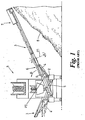
- FIG. 1 a known mobile aggregate processing plant 1 which comprises a chassis 2 upon which a pair of lateral conveyors 3 are mounted.
- the plant comprises a screen (not shown) which distributes the screened material on to the lateral conveyors 3.
- the plant is shown in Figure 1 in an end elevation in order to clearly show the lateral conveyors 3 which are mounted on either side of the chassis 2 of the plant.
- Hydraulic rams 4 are operated to extend the conveyors from a stowed position adjacent the chassis for transport to the operating position shown in Figure 1 .
- the lateral conveyors comprise a tail section 5 adjacent to the chassis 2, a middle section 6 and a head section 7 remote from the chassis 2.
- the head section of the conveyor is mounted to the middle section through a pivot point P1 such that the head section can pivot around the pivot point as shown by axis A in figure 1 .
- Processed material passes along the lateral conveyors from the tail section to the head section and exits the head section to form a stock pile 8 under the head section.
- the middle section of the conveyor is supported against the tail section of the conveyor, which is immobile in relation to the chassis
- the middle section is pivotally connected to the tail section through pivot point P2 such that the middle section can be folded towards the chassis 2 in the direction of Arrow B.
- the lateral conveyors are supported on the chassis of the plant by support means 9 (only one of which is shown in Figure 1 for clarity) which are mounted to the tail section and middle section of the conveyor respectively.
- the tail section of the conveyor is, in turn, firmly mounted to the chassis.
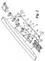
- FIG. 2 shows an exploded view of a lateral conveyor according to one aspect of the present invention.
- the support means 10 for the lateral conveyors of the present invention is in the form of a mounting arm 11a, 11b formed of a box section of mild steel. This may be extruded or cast to the appropriate lengths as required or may be a hollow section if preferred.
- a lateral flange 12 is provided adjacent one end 13 of the mounting arm 11a.
- Triangular support brackets 14 are formed under the flange 12 between the underside of the flange and the mounting arm 11a
- the other end of the mounting arm, remote from the flange 12 is mounted to a C-shaped bracket 15 through a rotational mounting shaft 16 shown in more detail in Figure 3 .
- the C-shaped bracket has a substantially flat top face 17 and a substantially flat bottom face 18 and a back plate 19 extending between the two.
- the top face and bottom face of the bracket are provided with apertures 20 which are aligned on a common axis of the bracket.
- the rotational mounting shaft 16 passes through corresponding aperture (not shown) in the back plate 19 of the bracket and the end face 21 of the mounting arm such that the mounting arm can rotate around its longitudinal axis upon the rotational mounting shaft.
- a bearing (not shown) may be provided between the end face 21 of the mounting arm and the back plate 19 of the bracket in order to facilitate rotation of the mounting arm.
- the means for attaching the mounting arm 11a to the conveyor is shown in detail in Figure 3 .
- a swivel mounting shaft 22 is provided to facilitate traversing of the mounting means around axis F in Figure 2 and comprising a cylindrical shaft member 23 which is attached to the conveyor's head section at one end and is provided with a head section 24 at the distal end, the head section having a greater diameter than the shaft.
- the head section 24 of the cylindrical shaft member is dimensioned to be mounted between the top and bottom faces 17, 18 of the C-shaped bracket 15 and is provided with a through bore 25 which is aligned with the apertures 20 in the top and bottom faces of the bracket when the head section 24 is presented to the bracket.
- a pivot mounting shaft 26 extends through the apertures 20 and the through bore 25 to retain the head section 24 of the swivel mounting means within the bracket 15.
- the pivot mounting shaft 26 facilitates elevation of the mounting arm 11a around axis E shown in Figure 2 by allowing the bracket 15 to pivot around the shaft 26.
- Bearings may be provided between the head section 24 of the swivel mounting shaft 22 and the top and bottom faces 17, 18 of the bracket.
- the articulated joint between the head section 7 and the mounting arm 11a provides three degrees of freedom.
- Figure 4 shows a schematic view of the connection of the mounting arm 11b to the tail section 5 of the conveyor.
- the distal end of the lower section 11b of the mounting arm is provided with an articulated joint having at least two degrees of freedom.
- the lower section 11b of the mounting arm is mounted to the chassis through the swivel mounting shaft 22b of the lower articulated joint which is similar to the joint connecting the upper section of the mounting arm 11a to the head section 7.
- Mounting arm 11b can rotate with the swivel mounting shaft 22b around axis G shown in Figure 2 and can pivot about the pivot mounting shaft 26b around axis H shown in Figure 2 .
- a further rotational mounting shaft may be provided between the end of the mounting arm 11b and the C-shaped bracket 15b to allow for a further rotation of the mounting arm 11b with respect to the bracket 15b. This would provide the joint between the tail section and the mounting arm 11b with a third degree of freedom, which is acceptable but not necessary for carrying out the invention.
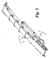
- Hydraulic cylinders 4 are mounted between the tail section 5 and the middle section 6 and the middle section 6 and the head section 7 of the lateral conveyors 3 for extending the conveyors between the operating and the stowed or transit positions.
- a first hydraulic cylinder 4a acts to extend the conveyor out from the chassis around axis I shown in Figure 5
- a second hydraulic cylinder 4b is used to fold the head section of the conveyor back towards the chassis around axis J shown in Figure 5 during transfer from the operating to the transit position as will be described in more detail below.
- a collar 27 is provided between the free ends of the mounting arms 11a and 11b as shown in detail in Figure 6 .
- the collar is provided with apertures (not shown) which align with apertures 27' in the mounting 11b, one of which is shown in Figure 2 .
- a pin 28 is provided through the apertures in the collar and the mounting arm 11b.
- the collar is provided with a lateral flange 29 of similar dimensions to the lateral flange 12 of the upper mounting arm section 11a and is also provided with triangular brackets 30 similar to the brackets 14 described above.
- the flange 29 is provided with threaded aperture (not shown) to receive a locking member 31 which is held in position by a threaded nut 32 or other suitable locking means.
- the collar surrounds the free end of mounting arm section 11b and is fixed thereto with pin 28. The free end of mounting arm section 11a rests on the collar as a result of gravity.
- the lateral conveyors are supported on the chassis in an extended position.
- the threaded nut 32 is loosened and the locking bolt 31 is turned either to increase or to decrease the distance between the flanges 12 and 29 in order to provide fine adjustment of the length of the arm. It is an advantage of the present invention that adjustment of the tracking of the belt can occur during use of the conveyor 3 from a position remote from the head section of the conveyor as this does not require the head section of the conveyor to be lowered to the ground nor are personnel required to stand in the vicinity of the stock pile 8 under the head section 7 of the conveyor where injuries could occur from falling material or close to the running belt, which always creates a hazard of drawing-in.
- the lateral conveyors 3 are moved from the operating position when they extend outboard of the chassis to a stored or transit position inboard of the chassis.
- Nut 32 and the locking bolt 31 are loosened and stopper pin 28 is removed from the apertures in the collar to allow the lower section of the mounting arm 11b to be telescopically received within the upper section of the mounting arm 11a.
- Hydraulic valves (not shown) are opened to operate the first hydraulic cylinder 4a to fold up the middle section of the conveyor 3 and the second hydraulic cylinder 4b to fold the head section 7 of the conveyor sidewards.
- the mounting arm 11 pivots around the pivot mounting shaft.
- the mounting arm swivels on the swivel mounting shaft.
- the length of the mounting arm telescopically alters and the collar and pin are used to lock the length of the mounting arm at the desired length.
- the C-shaped member rotates on the rotational mounting shaft with respect to the mounting arm.
- the conveyor may be extended through the first plane and then traversed through the second plane, or this order can be reversed, or alternatively, both movements may occur simultaneously.
- the conveyor Once the conveyor is in the transport position, it may be locked in this position by replacement of the pin 28.
- the head section can be folded down without moving the conveyor into the transport position.
- the head section may be locked in the service position by replacement of the stopper pin as described above.
- a variable length support means having an articulated joint with 3 degrees of movement in one end and at least 2 degrees of movement in the other end as described above allows for a longer mounting arm to be used than was possible with prior art conveyors as the longer mounting arm of the present invention can still be accommodated within the dimensions of the chassis of the plant when the conveyor is in the transport position.
- a longer mounting arm can be used, therefore a longer conveyor can be supported upon the chassis of the plant.
- Use of a longer conveyor enables a greater capacity of material to be processed during operation of the plant.
- the load on the conveyor is spread along a greater length of the conveyor frame and provides a more stable plant than was previously available which is not as susceptible to unfavorable working conditions such as soft or uneven ground of the worksite causing extensive vibration.
- the tracking of the belt of the conveyor can be adjusted during operation. This is a significant advantage over prior art conveyors where the tracking is adjusted by altering the position of the belt on rollers within the head section of the conveyor which has to be done by lowering the head section to ground level. Such an operation could only take place during an interruption of the processing operation.
- the lateral conveyor has been described above as having three sections, a tail section, a middle section and a head section, it is envisaged that the head section of the conveyor can also be divided into separate subsections pivotable with respect to each other.
- the embodiment provides a joint between mounting arm 11a and the head section 7 of the conveyor with three degrees of freedom and a joint between mounting arm 11b and the tail section 5 of the conveyor with two degrees of freedom.
- these two types of joints can replace each other. Also both joints can provide three degrees of freedom.
- the embodiment provides a support extending between the head section 7 of the conveyor and the tail section 5 of the conveyor.
- hydraulic cylinder driving means other driving means may be used for example, hydraulic motors, pneumatic cylinders, pneumatic motors or electric motors with the necessary power transmission means. These driving means are preferably double acting for forward and backward movement.
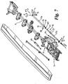
- Figures 7 to 9 provide schematic views of a lateral conveyor according to another embodiment of the present invention. Most of the components of the embodiment of Figures 7 to 9 are the same as those of the embodiment of Figures 2 to 4 and thus reference should be made to the description given above with reference to Figures 2 to 4 . Here, differences between the embodiment of Figures 2 to 4 and the embodiment of Figures 2 to 4 will be described.
- Figure 7 provides an exploded view of the lateral conveyor according to the other embodiment.
- This embodiment provides for two degrees of freedom of movement in the connection of the mounting arm 11a to the head section 7 of the conveyor instead of the three degrees of freedom of movement of the previous embodiment.
- the two degrees of freedom of movement are: elevation of the mounting arm 11a around axis E by allowing the bracket 15 to pivot around the shaft 26; and traversing of the mounting means around axis F by means of the swivel mounting shaft 22.
- Figure 8 provides an enlarged schematic side view of the end of mounting arm 11a shown in Figure 7 . It is not required of this embodiment that the mounting arm 11a rotates around axis D. However, this embodiment may also be configured in the same way as the previous embodiment for rotation of the mounting arm 11a around axis D.
- mounting arm 11b is connected to the tail section 5 of the conveyer in the same way as the previous embodiment.
- the connection of Figure 9 provides for two degrees of freedom of movement in common with the previous embodiment.
- a further rotational mounting shaft may be provided between the end of the mounting arm 11b and the C-shaped bracket 15b to allow for a further rotation of the mounting arm 11b with respect to the bracket 15b. This provides the joint between the tail section and the mounting arm 11b with a third degree of freedom, which is acceptable but not necessary for carrying out the invention.
- a collar 40 is provided between the free ends of the mounting arms 11a and 11b.
- One of the two mounting arms 11a and 11b is received in the other and provides for telescopic variation of the length of the support means 10.
- the co-locating ends 13 and 41 of the two mounting arms 11a and 11b are of substantially circular cross-section, the two mounting arms 11a and 11b are rotatable in relation to each other about axis D.
- the collar 40 is configured to cooperate with the circular cross sections of the ends of the two mounting arms 11a and 11b. This means that in this embodiment, two degrees of freedom of movement are provided by the connection between mounting arms 11a and 11b, whereas in the previous embodiment there is only one degree of freedom of movement, namely relative linear movement of the two mounting arms 11a and 11b.
- connection between the mounting arm 11a and the head section 7 provides for two degrees of freedom of movement and the connection between the two mounting arms 11a and 11b provides for two degrees of freedom of movement.
- connection between the mounting arm 11a and the head section 7 provides for three degrees of freedom of movement and the connection between the two mounting arms 11a and 11b provides for one degree of freedom of movement.
- the support means of this invention finds use in the aggregate material processing industry.
Claims (26)
- Ein Seitenförderer, der zum Montieren auf einem mobilen Fahrgestell angepasst ist und wischen einer Arbeitsposition, in der sich der Seitenförderer außerhalb des Fahrgestells erstreckt, und einer Transportposition bewegbar ist; der Folgendes beinhaltet:a) einen hinteren Teilabschnitt (5) zum Montieren an dem mobilen Fahrgestell,b) einen mittleren Teilabschnitt (6),c) mindestens einen vorderen Teilabschnitt (7),d) ein Stützmittel (10), das einen Montagearm mit einem ersten und einem zweiten Ende beinhaltet, wobei der Montagearm einen ersten Teilabschnitt (11a) und einen zweiten Teilabschnitt (11 b) beinhaltet, wobei einer der zwei Teilabschnitte (11 a; 11 b) konfiguriert ist, um in Bezug auf den anderen zu gleiten, um die Länge des Montagearms zu variieren, wobei das Stützmittel (10) darüber hinaus Mittel (27, 40) zum Arretieren der Länge des Montagearms in mindestens einer fixierten Länge, die der Länge des Förderers in der Arbeitsposition entspricht, beinhaltet,e) wobei der mittlere Teilabschnitt (6) in Bezug auf den hinteren Teilabschnitt (5) um eine erste Achse (I), die im Wesentlichen zu einer Seitenachse des mittleren Teilabschnitts (6) parallel ist, schwenkbar ist,f) wobei der vordere Teilabschnitt (7) in Bezug auf den mittleren Teilabschnitt (6) um eine zweite Achse (J), die im Wesentlichen zu einer Längsachse und zu einer Seitenachse des mittleren Teilabschnitts (6) senkrecht ist, schwenkbar ist,g) wobei das erste Ende des Montagearms mit einem Mittel zum Fixieren des Montagearms an dem mobilen Fahrgestell oder einem in Bezug auf das mobile Fahrgestell unbeweglich fixierten Teil versehen ist,h) wobei das zweite Ende des Montagearms an dem vorderen Teilabschnitt (7) oder einem in Bezug auf den vorderen Teilabschnitt (7) des Förderers umbeweglich fixierten Teil fixiert ist,i) wobei ein erstes kinematisches Paar durch den ersten Teilabschnitt (11 a) des Montagearms und das mobile Fahrgestell gebildet wird und durch ein erstes Gelenk bereitgestellt wird,j) ein zweites kinematisches Paar durch den ersten und zweiten Teilabschnitt (11 a; 11 b) des Montagearms gebildet wird,k) ein drittes kinematisches Paar durch den zweiten Teilabschnitt (11 b) des Montagearms und den vorderen Teilabschnitt (7) des Förderers gebildet wird und durch ein zweites Gelenk bereitgestellt wird,l) wobei das erste kinematische Paar zwei oder drei Rotationsfreiheitsgrade der Bewegung bereitstellt und das dritte kinematische Paar zwei oder drei Rotationsfreiheitsgrade der Bewegung bereitstellt,
und wobei:mindestens eines von dem ersten kinematischen Paar oder dem dritten kinematischen Paar drei Rotationsfreiheitsgrade der Bewegung bereitstellt;und/oder das zweite kinematische Paar bereitstellt, dass der erste und zweite Teilabschnitt für Rotation in Bezug aufeinander um ihre Längsachse (D) konfiguriert sind. - Seitenförderer gemäß Anspruch 1, wobei das erste und zweite Gelenk so konfiguriert sind, dass das erste kinematische Paar drei Rotationsfreiheitsgrade der Bewegung bereitstellt und das dritte kinematische Paar zwei Rotationsfreiheitsgrade der Bewegung bereitstellt.
- Seitenförderer gemäß Anspruch 1, wobei das erste und zweite Gelenk so konfiguriert sind, dass das erste kinematische Paar zwei Rotationsfreiheitsgrade der Bewegung bereitstellt und das dritte kinematische Paar drei Rotationsfreiheitsgrade der Bewegung bereitstellt.
- Seitenförderer gemäß Anspruch 1, wobei das erste und zweite Gelenk so konfiguriert sind, dass sowohl das erste als auch das dritte kinematische Paar drei Rotationsfreiheitsgrade der Bewegung bereitstellt.
- Seitenförderer gemäß Anspruch 1, 2 oder 3, wobei das erste Gelenk und/oder das zweite Gelenk, die die zwei Rotationsfreiheitsgrade der Bewegung des ersten kinematischen Paars und/oder des dritten kinematischen Paars bereitstellen, wie jeweils anwendbar, einen Schwenkmontageschaft (26b) und einen Drehmontageschaft (22b) beinhalten, wobei der Montagearm in einer einen Ebene durch Schwenken um den Schwenkmontageschaft erhöht und in einer anderen Ebene durch Drehen an dem Drehmontageschaft seitwärts gedreht werden kann.
- Seitenförderer gemäß einem der vorhergehenden Ansprüche 1-4, wobei das erste Gelenk und/oder das zweite Gelenk, die die drei Rotationsfreiheitsgrade der Bewegung des ersten kinematischen Paars und/oder des dritten kinematischen Paars bereitstellen, wie jeweils anwendbar, ein Schwenkmontageschaft (26), ein Drehmontageschaft (22) und ein Rotationsmontageschaft (16) beinhalten, wobei der Montagearm durch Schwenken um den Schwenkmontageschaft (26) in einer ersten Ebene erhöht und durch Drehen auf dem Drehmontageschaft (22) in einer zweiten Ebene seitwärts gedreht und auf dem Rotationsmontageschaft (16) um seine Längsachse (D, G) rotiert werden kann.
- Seitenförderer gemäß Anspruch 6, wobei die erste und zweite Ebene senkrecht sind.
- Seitenförderer gemäß Anspruch 7, wobei die Längsachse des zweiten Teilabschnitts (11 b) im Wesentlichen parallel zu einer Schnittlinie der Ebenen ist.
- Seitenförderer gemäß einem der Ansprüche 6 bis 8, wobei eine C-förmige Halterung (15), die eine obere Fläche (17), eine untere Fläche (18) und eine Rückplatte (19), welche sich zwischen der oberen und unteren Fläche erstreckt, beinhaltet, durch den Rotationsmontageschaft an mindestens einem Ende des Montagearms montiert ist.
- Seitenförderer gemäß Anspruch 9, wobei die obere und untere Fläche der C-förmigen Halterung (15) im Wesentlichen parallel sind und sich die Rückplatte (19) im Wesentlichen senkrecht zu der oberen und unteren Fläche (17; 18) erstreckt .
- Seitenförderer gemäß Anspruch 9 oder 10, wobei ein Lagerungsmittel zwischen einer Endfläche des Montagearms und der Rückplatte (19) der Halterung (15) bereitgestellt ist.
- Seitenförderer gemäß einem der Ansprüche 9 bis 11, wobei in jeder der oberen und unteren Fläche (17; 18) der C-förmigen Halterung (15) eine Öffnung (20) bereitgestellt ist, wobei die Öffnungen (20) entlang einer gemeinsamen Achse durch die Halterung (15) in eine Linie gebracht sind.
- Seitenförderer gemäß Anspruch 12, wobei der Drehmontageschaft (22) mit einer Durchbohrung (25) versehen ist und der Drehmontageschaft (22) innerhalb der C-förmigen Halterung (15) montiert ist, so dass die Bohrung (25) mit den Öffnungen (20) in der oberen und unteren Fläche (17; 18) der Halterung (15) in eine Linie gebracht ist.
- Seitenförderer gemäß Anspruch 13, wobei sich der Schwenkmontageschaft (26) durch die Öffnungen (20) in der oberen und unteren Fläche (17; 18) der C-förmigen Halterung (15) und die Durchbohrung (25) des Drehmontageschafts (22) erstreckt, um den Drehmontageschaft (22) innerhalb der Halterung (15) in Position zu arretieren.
- Seitenförderer gemäß einem der Ansprüche 1 bis 14, wobei der erste und zweite Teilabschnitt (11 a, 11 b) so konfiguriert sind, dass einer der zwei Teilabschnitte zum teleskopischen Variieren des Montagearms in dem anderen aufgenommen wird.
- Seitenförderer gemäß Anspruch 15, wobei der Montagearm einen hydraulischen Zylinder (4a, 4b) beinhaltet.
- Seitenförderer gemäß Anspruch 15 oder 16, wobei die Abschnitte zum Zusammenplatzieren (13, 41) des ersten und zweiten Teilabschnitts (11a, 11 b) einen im Wesentlichen kreisförmigen Querschnitt beinhalten, so dass der erste und zweite Teilabschnitt (11a, 11 b) um ihre Längsachse (D) zueinander rotierbar sind.
- Seitenförderer gemäß einem der vorhergehenden Ansprüche, wobei der Montagearm drei Teilabschnitte beinhaltet, die so angeordnet sind, dass einer des ersten und zweiten Teilabschnitts zum Gleiten in Bezug auf den anderen konfiguriert ist, um die Länge des Montagearms zu variieren, und der zweite und dritte Teilabschnitt zur Rotation in Bezug aufeinander um ihre Längsachse konfiguriert sind.
- Seitenförderer gemäß einem der vorhergehenden Ansprüche, wobei das Mittel (27, 40) zum Arretieren der Länge des Montagearms mit variabler Länge angepasst ist, um eine Länge, die der Länge des Seitenförderers in der Transportposition und/oder Arbeitsposition entspricht, zu fixieren.
- Seitenförderer gemäß einem der vorhergehenden Ansprüche, wobei der vordere Teilabschnitt (7) des Förderers aus mindestens zwei separaten Teilabschnitten, die schwenkbar zueinander sind, besteht, wobei der erste der vorderen Teilabschnitte mit dem Arm mit variabler Länge an dem mobilen Fahrgestell oder einem in Bezug auf das mobile Fahrgestell unbeweglich fixierten Teil gestützt ist.
- Seitenförderer gemäß einem der vorhergehenden Ansprüche, wobei das Mittel zum Arretieren der Länge des Montagearms einen Stellring (40) und einen Arretierstift (28) beinhaltet, die bereitgestellt sind, um die Länge des Montagearms zu fixieren, damit er der Arbeitsposition des Förderers entspricht, vorzugsweise auch der Transportposition und einer Wartungsposition.
- Seitenförderer gemäß einem der vorhergehenden Ansprüche, wobei zwischen allen Gleitflächen ein Lagerungsmittel bereitgestellt ist.
- Seitenförderer gemäß einem der vorhergehenden Ansprüche, wobei das Stützmittel aus Weichstahl gebildet ist.
- Seitenförderer gemäß einem der vorhergehenden Ansprüche, wobei Einstellmittel bereitgestellt sind, um die Länge des Montagearms, wenn in der mindestens einen fixierten Länge arretiert, fein abgestimmt zu ändern.
- Ein mobiles Fahrgestell, das einen darauf montierten Seitenförderer gemäß einem der vorhergehenden Ansprüche beinhaltet.
- Mobiles Fahrgestell gemäß Anspruch 25, wobei das mobile Fahrgestell eine mobile Aggregatverarbeitungsanlage ist.
Priority Applications (1)
| Application Number | Priority Date | Filing Date | Title |
|---|---|---|---|
| PL04730598T PL1628896T3 (pl) | 2003-05-02 | 2004-04-30 | Przenośnik poprzeczny i ruchome podwozie obejmujące taki przenośnik poprzeczny |
Applications Claiming Priority (2)
| Application Number | Priority Date | Filing Date | Title |
|---|---|---|---|
| GB0310177 | 2003-05-02 | ||
| PCT/GB2004/001922 WO2004096677A1 (en) | 2003-05-02 | 2004-04-30 | Support means for a lateral conveyor on a mobile chassis |
Publications (2)
| Publication Number | Publication Date |
|---|---|
| EP1628896A1 EP1628896A1 (de) | 2006-03-01 |
| EP1628896B1 true EP1628896B1 (de) | 2012-08-01 |
Family
ID=32408049
Family Applications (1)
| Application Number | Title | Priority Date | Filing Date |
|---|---|---|---|
| EP04730598A Expired - Lifetime EP1628896B1 (de) | 2003-05-02 | 2004-04-30 | Seitenförderer und fahrgestell mit einem solchen seitenförderer |
Country Status (7)
| Country | Link |
|---|---|
| US (1) | US7552818B2 (de) |
| EP (1) | EP1628896B1 (de) |
| JP (1) | JP5021296B2 (de) |
| ES (1) | ES2391045T3 (de) |
| GB (1) | GB2401846B (de) |
| PL (1) | PL1628896T3 (de) |
| WO (1) | WO2004096677A1 (de) |
Cited By (2)
| Publication number | Priority date | Publication date | Assignee | Title |
|---|---|---|---|---|
| DE102015104498A1 (de) | 2015-03-25 | 2016-09-29 | Kleemann Gmbh | Klapp-Mechanismus für eine Fördereinrichtung |
| EP4344785A1 (de) | 2022-09-29 | 2024-04-03 | SBM Mineral Processing GmbH | Prozessiervorrichtung |
Families Citing this family (20)
| Publication number | Priority date | Publication date | Assignee | Title |
|---|---|---|---|---|
| US6935587B2 (en) | 2002-06-06 | 2005-08-30 | Johnson Crushers International | Mobile rock crushing plant |
| US7464889B2 (en) | 2002-06-06 | 2008-12-16 | Johnson Crushers International | Mobile rock crushing plant |
| US7264104B2 (en) | 2005-03-11 | 2007-09-04 | Johnson Crushers International | Crusher in-feed conveyor method and apparatus |
| WO2007065965A1 (en) * | 2005-12-09 | 2007-06-14 | Metso Minerals Inc. | Material processing apparatus comprising a conveyor |
| EP2001606A2 (de) * | 2006-02-16 | 2008-12-17 | Aughey Research and Designs Limited | Materialsiebvorrichtung |
| EP2137090B1 (de) * | 2007-03-07 | 2013-11-06 | Terex GB Limited | Materialbearbeitungsvorrichtung mit faltbarem rahmen |
| US7891479B2 (en) | 2007-09-07 | 2011-02-22 | Carl Evangelista | Modular conveyor system |
| US20100008750A1 (en) * | 2008-07-08 | 2010-01-14 | Dan Jones, Inc. | Trailers,systems and methods for transferring material |
| US7708131B2 (en) * | 2008-09-02 | 2010-05-04 | Gordon Muth | Swing auger hopper drive |
| US7997406B2 (en) * | 2009-05-14 | 2011-08-16 | Flsmidth A/S | Conveyor apparatus |
| US8876216B2 (en) | 2010-02-26 | 2014-11-04 | All Right Steel, Llc | Dump trailer |
| RU2558526C2 (ru) | 2010-02-26 | 2015-08-10 | ОЛЛ РАЙТ СТИЛ ЭлЭлСи | Самосвальный прицеп |
| GB2507767A (en) * | 2012-11-08 | 2014-05-14 | Terex Gb Ltd | Conveyor adjustable input support frame |
| US9376260B2 (en) * | 2014-02-06 | 2016-06-28 | Metso Minerals, Inc. | Conveyor body and mobile mineral material processing plant |
| DE102015003239A1 (de) * | 2015-03-10 | 2016-09-15 | Beumer Gmbh & Co. Kg | Vorrichtung zum Be- oder Entladen einen Transportbehälters |
| US9549505B1 (en) * | 2015-09-21 | 2017-01-24 | Deere & Company | Agricultural vehicle conveyance linkage |
| CN108945982A (zh) * | 2018-08-03 | 2018-12-07 | 四川高通环保科技股份有限公司 | 生活垃圾分类处理皮带输送机 |
| US10781864B2 (en) | 2018-11-16 | 2020-09-22 | Glg Farms Llc | Drive wheel clutch system |
| CN110817338A (zh) * | 2019-12-05 | 2020-02-21 | 华电重工股份有限公司 | 物料输送机用柔性机架及带式输送机 |
| FI130584B (en) * | 2022-01-31 | 2023-11-23 | Metso Finland Oy | Conveyor system of a mobile mineral material handling plant |
Family Cites Families (24)
| Publication number | Priority date | Publication date | Assignee | Title |
|---|---|---|---|---|
| CA926382A (en) | 1970-01-15 | 1973-05-15 | Rossi Lionello | Articulated pivotable continuous conveyor mounted on a wheeled frame, preferably carrying also a rotating mixer |
| US3768784A (en) * | 1971-12-16 | 1973-10-30 | Symons Corp | Distributing conveyor system for a rotary concrete mixing or other truck |
| JPS5416458Y2 (de) * | 1975-06-18 | 1979-06-28 | ||
| JPS5820572Y2 (ja) * | 1979-09-30 | 1983-04-28 | ナショナル住宅産業株式会社 | 搬送装置 |
| CA1191487A (en) * | 1981-11-06 | 1985-08-06 | Richard Crawshay | Continuous loading apparatus and method |
| JPS58161917U (ja) * | 1982-04-23 | 1983-10-28 | ナショナル住宅産業株式会社 | 作業台兼用直交搬送装置 |
| US4579479A (en) * | 1984-04-26 | 1986-04-01 | Bryant Joseph H | Pothole patching and roadway surface paving machine |
| US4780041A (en) * | 1987-08-03 | 1988-10-25 | Ashby Jr Charles W | Extendable conveyor system |
| US5333725A (en) * | 1989-12-22 | 1994-08-02 | Douglas Patrick J | Foldable framework for belt conveyor |
| US5123519A (en) * | 1991-02-12 | 1992-06-23 | Edw. C. Levy Company | Knuckled hydraulically-actuated stacking coveyor |
| US5184715A (en) * | 1991-05-09 | 1993-02-09 | Core Industries, Inc. | Mechanical drive for dual conveyor system |
| US5178253A (en) * | 1991-08-26 | 1993-01-12 | Ingersoll-Rand Company | Swing mechanism for a vehicular conveyor |
| US5348130A (en) * | 1993-07-30 | 1994-09-20 | Joy Mm Delaware, Inc. | Advanceable auxiliary conveying apparatus |
| US5577618A (en) * | 1993-09-07 | 1996-11-26 | Rafferty; Malachy J. | Mobile aggregate material processing plant |
| US5562194A (en) * | 1995-03-06 | 1996-10-08 | Krupp Fordertechnik Gmbh | Conveyor-displacing system and method for mining operation |
| US5779321A (en) * | 1996-11-12 | 1998-07-14 | Arch Technology Corporation | Swing tail assembly for miner |
| US6360873B1 (en) * | 1997-09-19 | 2002-03-26 | The Mead Corporation | Article grouping mechanism |
| US6283269B1 (en) * | 1999-12-03 | 2001-09-04 | Putzmeister, Inc. | Vehicle-mounted extendable conveyor having variable angle infeed conveyor assembly |
| US6296109B1 (en) * | 2000-02-02 | 2001-10-02 | Astec Industries Inc. | Fold linkage and method of using same |
| US6698594B2 (en) * | 2002-03-18 | 2004-03-02 | Ohio Central Steel Company | Screening machine |
| DE20101395U1 (de) * | 2001-01-26 | 2001-04-26 | Voegele Ag J | Beschicker und Montagevorrichtung |
| US7273150B2 (en) * | 2003-12-29 | 2007-09-25 | Wildcat Manufacturing Co., Inc. | Portable screening machine |
| US7191889B1 (en) * | 2004-12-14 | 2007-03-20 | Heley Kenneth J | Remote controlled swing auger system |
| US7261200B1 (en) * | 2007-01-08 | 2007-08-28 | Spudnik Equipment Company, Llc | Assembly for moving and rotating conveyor |
-
2004
- 2004-04-30 GB GB0409678A patent/GB2401846B/en not_active Expired - Fee Related
- 2004-04-30 JP JP2006506216A patent/JP5021296B2/ja not_active Expired - Fee Related
- 2004-04-30 EP EP04730598A patent/EP1628896B1/de not_active Expired - Lifetime
- 2004-04-30 ES ES04730598T patent/ES2391045T3/es not_active Expired - Lifetime
- 2004-04-30 PL PL04730598T patent/PL1628896T3/pl unknown
- 2004-04-30 US US10/555,152 patent/US7552818B2/en active Active
- 2004-04-30 WO PCT/GB2004/001922 patent/WO2004096677A1/en active Application Filing
Cited By (4)
| Publication number | Priority date | Publication date | Assignee | Title |
|---|---|---|---|---|
| DE102015104498A1 (de) | 2015-03-25 | 2016-09-29 | Kleemann Gmbh | Klapp-Mechanismus für eine Fördereinrichtung |
| WO2016150727A1 (de) | 2015-03-25 | 2016-09-29 | Kleemann Gmbh | Klapp-mechanismus für eine fördereinrichtung |
| DE102015104498B4 (de) | 2015-03-25 | 2022-05-25 | Kleemann Gmbh | Klapp-Mechanismus für eine Fördereinrichtung |
| EP4344785A1 (de) | 2022-09-29 | 2024-04-03 | SBM Mineral Processing GmbH | Prozessiervorrichtung |
Also Published As
| Publication number | Publication date |
|---|---|
| US20070158162A1 (en) | 2007-07-12 |
| PL1628896T3 (pl) | 2012-12-31 |
| EP1628896A1 (de) | 2006-03-01 |
| WO2004096677A1 (en) | 2004-11-11 |
| ES2391045T3 (es) | 2012-11-20 |
| GB0409678D0 (en) | 2004-06-02 |
| US7552818B2 (en) | 2009-06-30 |
| JP5021296B2 (ja) | 2012-09-05 |
| GB2401846A (en) | 2004-11-24 |
| JP2006525206A (ja) | 2006-11-09 |
| GB2401846B (en) | 2007-12-12 |
Similar Documents
| Publication | Publication Date | Title |
|---|---|---|
| EP1628896B1 (de) | Seitenförderer und fahrgestell mit einem solchen seitenförderer | |
| US5360097A (en) | Mobile conveyor system | |
| EP0641607B1 (de) | Mobile Anlage für die Behandlung von Aggregatmaterial | |
| RU2636063C2 (ru) | Установка для обработки материала | |
| JP3215198B2 (ja) | 走行可能な破砕装置 | |
| US7455173B1 (en) | Portable telescoping stacking conveyor | |
| US8783443B2 (en) | Material processing plant | |
| EP2977107B1 (de) | Bewegliche verarbeitungsvorrichtung zur verarbeitung von mineralischem material | |
| US9539578B2 (en) | Main frame for mobile bulk processing apparatus | |
| US20080121744A1 (en) | Frame Of A Movable Processing Device Of Mineral Materials, And A Multi-Purpose Fastening Device | |
| GB2478824A (en) | Conveyor system | |
| GB2351247A (en) | Mobile screening apparatus | |
| US8371430B2 (en) | Low profile telescopic conveyor assembly | |
| CN111547473A (zh) | 可调万向回转装置及采用该装置的单体式和整体式皮带机 | |
| RU2787096C2 (ru) | Корпус мобильного грохота и мобильная установка для обработки минерального материала с опорными ножками | |
| CN217597450U (zh) | 混凝土搅拌运输车 | |
| CN212126613U (zh) | 一种整体履带式移动皮带机 | |
| JPH0788395A (ja) | 路上走行可能な破砕プラント車 |
Legal Events
| Date | Code | Title | Description |
|---|---|---|---|
| PUAI | Public reference made under article 153(3) epc to a published international application that has entered the european phase |
Free format text: ORIGINAL CODE: 0009012 |
|
| 17P | Request for examination filed |
Effective date: 20051201 |
|
| AK | Designated contracting states |
Kind code of ref document: A1 Designated state(s): AT BE BG CH CY CZ DE DK EE ES FI FR GB GR HU IE IT LI LU MC NL PL PT RO SE SI SK TR |
|
| DAX | Request for extension of the european patent (deleted) | ||
| 17Q | First examination report despatched |
Effective date: 20070226 |
|
| RAP1 | Party data changed (applicant data changed or rights of an application transferred) |
Owner name: METSO MINERALS, INC. |
|
| GRAP | Despatch of communication of intention to grant a patent |
Free format text: ORIGINAL CODE: EPIDOSNIGR1 |
|
| RTI1 | Title (correction) |
Free format text: LATERAL CONVEYOR AND MOBILE CHASSIS COMPRISING SUCH A LATERAL CONVEYOR |
|
| RBV | Designated contracting states (corrected) |
Designated state(s): AT BE BG CH CY CZ DE DK EE ES FI FR GR HU IE IT LI LU MC NL PL PT RO SE SI SK TR |
|
| GRAS | Grant fee paid |
Free format text: ORIGINAL CODE: EPIDOSNIGR3 |
|
| GRAA | (expected) grant |
Free format text: ORIGINAL CODE: 0009210 |
|
| AK | Designated contracting states |
Kind code of ref document: B1 Designated state(s): AT BE BG CH CY CZ DE DK EE ES FI FR GR HU IE IT LI LU MC NL PL PT RO SE SI SK TR |
|
| REG | Reference to a national code |
Ref country code: DE Ref legal event code: R082 Ref document number: 602004038729 Country of ref document: DE Representative=s name: MURGITROYD & COMPANY, DE |
|
| REG | Reference to a national code |
Ref country code: AT Ref legal event code: REF Ref document number: 568552 Country of ref document: AT Kind code of ref document: T Effective date: 20120815 Ref country code: CH Ref legal event code: EP |
|
| REG | Reference to a national code |
Ref country code: IE Ref legal event code: FG4D |
|
| REG | Reference to a national code |
Ref country code: DE Ref legal event code: R096 Ref document number: 602004038729 Country of ref document: DE Effective date: 20120927 |
|
| REG | Reference to a national code |
Ref country code: SE Ref legal event code: TRGR Ref country code: ES Ref legal event code: FG2A Ref document number: 2391045 Country of ref document: ES Kind code of ref document: T3 Effective date: 20121120 |
|
| REG | Reference to a national code |
Ref country code: NL Ref legal event code: VDEP Effective date: 20120801 |
|
| REG | Reference to a national code |
Ref country code: PL Ref legal event code: T3 |
|
| PG25 | Lapsed in a contracting state [announced via postgrant information from national office to epo] |
Ref country code: CY Free format text: LAPSE BECAUSE OF FAILURE TO SUBMIT A TRANSLATION OF THE DESCRIPTION OR TO PAY THE FEE WITHIN THE PRESCRIBED TIME-LIMIT Effective date: 20120801 |
|
| PG25 | Lapsed in a contracting state [announced via postgrant information from national office to epo] |
Ref country code: PT Free format text: LAPSE BECAUSE OF FAILURE TO SUBMIT A TRANSLATION OF THE DESCRIPTION OR TO PAY THE FEE WITHIN THE PRESCRIBED TIME-LIMIT Effective date: 20121203 Ref country code: BE Free format text: LAPSE BECAUSE OF FAILURE TO SUBMIT A TRANSLATION OF THE DESCRIPTION OR TO PAY THE FEE WITHIN THE PRESCRIBED TIME-LIMIT Effective date: 20120801 Ref country code: GR Free format text: LAPSE BECAUSE OF FAILURE TO SUBMIT A TRANSLATION OF THE DESCRIPTION OR TO PAY THE FEE WITHIN THE PRESCRIBED TIME-LIMIT Effective date: 20121102 Ref country code: SI Free format text: LAPSE BECAUSE OF FAILURE TO SUBMIT A TRANSLATION OF THE DESCRIPTION OR TO PAY THE FEE WITHIN THE PRESCRIBED TIME-LIMIT Effective date: 20120801 |
|
| PG25 | Lapsed in a contracting state [announced via postgrant information from national office to epo] |
Ref country code: NL Free format text: LAPSE BECAUSE OF FAILURE TO SUBMIT A TRANSLATION OF THE DESCRIPTION OR TO PAY THE FEE WITHIN THE PRESCRIBED TIME-LIMIT Effective date: 20120801 |
|
| PG25 | Lapsed in a contracting state [announced via postgrant information from national office to epo] |
Ref country code: DK Free format text: LAPSE BECAUSE OF FAILURE TO SUBMIT A TRANSLATION OF THE DESCRIPTION OR TO PAY THE FEE WITHIN THE PRESCRIBED TIME-LIMIT Effective date: 20120801 Ref country code: CZ Free format text: LAPSE BECAUSE OF FAILURE TO SUBMIT A TRANSLATION OF THE DESCRIPTION OR TO PAY THE FEE WITHIN THE PRESCRIBED TIME-LIMIT Effective date: 20120801 Ref country code: EE Free format text: LAPSE BECAUSE OF FAILURE TO SUBMIT A TRANSLATION OF THE DESCRIPTION OR TO PAY THE FEE WITHIN THE PRESCRIBED TIME-LIMIT Effective date: 20120801 Ref country code: RO Free format text: LAPSE BECAUSE OF FAILURE TO SUBMIT A TRANSLATION OF THE DESCRIPTION OR TO PAY THE FEE WITHIN THE PRESCRIBED TIME-LIMIT Effective date: 20120801 |
|
| PG25 | Lapsed in a contracting state [announced via postgrant information from national office to epo] |
Ref country code: SK Free format text: LAPSE BECAUSE OF FAILURE TO SUBMIT A TRANSLATION OF THE DESCRIPTION OR TO PAY THE FEE WITHIN THE PRESCRIBED TIME-LIMIT Effective date: 20120801 |
|
| PLBE | No opposition filed within time limit |
Free format text: ORIGINAL CODE: 0009261 |
|
| STAA | Information on the status of an ep patent application or granted ep patent |
Free format text: STATUS: NO OPPOSITION FILED WITHIN TIME LIMIT |
|
| 26N | No opposition filed |
Effective date: 20130503 |
|
| PG25 | Lapsed in a contracting state [announced via postgrant information from national office to epo] |
Ref country code: BG Free format text: LAPSE BECAUSE OF FAILURE TO SUBMIT A TRANSLATION OF THE DESCRIPTION OR TO PAY THE FEE WITHIN THE PRESCRIBED TIME-LIMIT Effective date: 20121101 |
|
| REG | Reference to a national code |
Ref country code: DE Ref legal event code: R097 Ref document number: 602004038729 Country of ref document: DE Effective date: 20130503 |
|
| PG25 | Lapsed in a contracting state [announced via postgrant information from national office to epo] |
Ref country code: MC Free format text: LAPSE BECAUSE OF FAILURE TO SUBMIT A TRANSLATION OF THE DESCRIPTION OR TO PAY THE FEE WITHIN THE PRESCRIBED TIME-LIMIT Effective date: 20120801 |
|
| REG | Reference to a national code |
Ref country code: CH Ref legal event code: PL |
|
| REG | Reference to a national code |
Ref country code: IE Ref legal event code: MM4A |
|
| PG25 | Lapsed in a contracting state [announced via postgrant information from national office to epo] |
Ref country code: LI Free format text: LAPSE BECAUSE OF NON-PAYMENT OF DUE FEES Effective date: 20130430 Ref country code: CH Free format text: LAPSE BECAUSE OF NON-PAYMENT OF DUE FEES Effective date: 20130430 |
|
| PG25 | Lapsed in a contracting state [announced via postgrant information from national office to epo] |
Ref country code: IE Free format text: LAPSE BECAUSE OF NON-PAYMENT OF DUE FEES Effective date: 20130430 |
|
| PG25 | Lapsed in a contracting state [announced via postgrant information from national office to epo] |
Ref country code: TR Free format text: LAPSE BECAUSE OF FAILURE TO SUBMIT A TRANSLATION OF THE DESCRIPTION OR TO PAY THE FEE WITHIN THE PRESCRIBED TIME-LIMIT Effective date: 20120801 |
|
| PG25 | Lapsed in a contracting state [announced via postgrant information from national office to epo] |
Ref country code: HU Free format text: LAPSE BECAUSE OF FAILURE TO SUBMIT A TRANSLATION OF THE DESCRIPTION OR TO PAY THE FEE WITHIN THE PRESCRIBED TIME-LIMIT; INVALID AB INITIO Effective date: 20040430 Ref country code: LU Free format text: LAPSE BECAUSE OF NON-PAYMENT OF DUE FEES Effective date: 20130430 |
|
| REG | Reference to a national code |
Ref country code: FR Ref legal event code: PLFP Year of fee payment: 13 |
|
| REG | Reference to a national code |
Ref country code: FR Ref legal event code: PLFP Year of fee payment: 14 |
|
| REG | Reference to a national code |
Ref country code: FR Ref legal event code: PLFP Year of fee payment: 15 |
|
| REG | Reference to a national code |
Ref country code: ES Ref legal event code: PC2A Owner name: SANDVIK INTELLECTUAL PROPERTY AB Effective date: 20200320 |
|
| REG | Reference to a national code |
Ref country code: FI Ref legal event code: PCE Owner name: SANDVIK INTELLECTUAL PROPERTY AB |
|
| PGFP | Annual fee paid to national office [announced via postgrant information from national office to epo] |
Ref country code: PL Payment date: 20200316 Year of fee payment: 17 |
|
| REG | Reference to a national code |
Ref country code: DE Ref legal event code: R082 Ref document number: 602004038729 Country of ref document: DE Representative=s name: MURGITROYD & COMPANY, DE Ref country code: DE Ref legal event code: R081 Ref document number: 602004038729 Country of ref document: DE Owner name: SANDVIK INTELLECTUAL PROPERTY AB, SE Free format text: FORMER OWNER: METSO MINERALS, INC., HELSINKI, FI |
|
| REG | Reference to a national code |
Ref country code: AT Ref legal event code: PC Ref document number: 568552 Country of ref document: AT Kind code of ref document: T Owner name: SANDVIK INTELLECTUAL PROPERTY AB, SE Effective date: 20200907 |
|
| PGFP | Annual fee paid to national office [announced via postgrant information from national office to epo] |
Ref country code: IT Payment date: 20210310 Year of fee payment: 18 Ref country code: FR Payment date: 20210325 Year of fee payment: 18 |
|
| PGFP | Annual fee paid to national office [announced via postgrant information from national office to epo] |
Ref country code: DE Payment date: 20210408 Year of fee payment: 18 Ref country code: FI Payment date: 20210409 Year of fee payment: 18 |
|
| PGFP | Annual fee paid to national office [announced via postgrant information from national office to epo] |
Ref country code: SE Payment date: 20210413 Year of fee payment: 18 Ref country code: AT Payment date: 20210325 Year of fee payment: 18 Ref country code: ES Payment date: 20210505 Year of fee payment: 18 |
|
| REG | Reference to a national code |
Ref country code: DE Ref legal event code: R119 Ref document number: 602004038729 Country of ref document: DE |
|
| REG | Reference to a national code |
Ref country code: AT Ref legal event code: MM01 Ref document number: 568552 Country of ref document: AT Kind code of ref document: T Effective date: 20220430 |
|
| REG | Reference to a national code |
Ref country code: SE Ref legal event code: EUG |
|
| PG25 | Lapsed in a contracting state [announced via postgrant information from national office to epo] |
Ref country code: SE Free format text: LAPSE BECAUSE OF NON-PAYMENT OF DUE FEES Effective date: 20220501 Ref country code: FR Free format text: LAPSE BECAUSE OF NON-PAYMENT OF DUE FEES Effective date: 20220430 Ref country code: FI Free format text: LAPSE BECAUSE OF NON-PAYMENT OF DUE FEES Effective date: 20220430 Ref country code: DE Free format text: LAPSE BECAUSE OF NON-PAYMENT OF DUE FEES Effective date: 20221103 Ref country code: AT Free format text: LAPSE BECAUSE OF NON-PAYMENT OF DUE FEES Effective date: 20220430 |
|
| PG25 | Lapsed in a contracting state [announced via postgrant information from national office to epo] |
Ref country code: PL Free format text: LAPSE BECAUSE OF NON-PAYMENT OF DUE FEES Effective date: 20210430 |
|
| PG25 | Lapsed in a contracting state [announced via postgrant information from national office to epo] |
Ref country code: IT Free format text: LAPSE BECAUSE OF NON-PAYMENT OF DUE FEES Effective date: 20220430 |
|
| REG | Reference to a national code |
Ref country code: ES Ref legal event code: FD2A Effective date: 20230601 |
|
| PG25 | Lapsed in a contracting state [announced via postgrant information from national office to epo] |
Ref country code: ES Free format text: LAPSE BECAUSE OF NON-PAYMENT OF DUE FEES Effective date: 20220501 |