EP2977107B1 - Movable processing apparatus for mineral material processing - Google Patents
Movable processing apparatus for mineral material processing Download PDFInfo
- Publication number
- EP2977107B1 EP2977107B1 EP15182626.0A EP15182626A EP2977107B1 EP 2977107 B1 EP2977107 B1 EP 2977107B1 EP 15182626 A EP15182626 A EP 15182626A EP 2977107 B1 EP2977107 B1 EP 2977107B1
- Authority
- EP
- European Patent Office
- Prior art keywords
- processing apparatus
- side conveyor
- frame
- movable
- pivot joint
- Prior art date
- Legal status (The legal status is an assumption and is not a legal conclusion. Google has not performed a legal analysis and makes no representation as to the accuracy of the status listed.)
- Revoked
Links
- 239000000463 material Substances 0.000 title claims description 29
- 229910052500 inorganic mineral Inorganic materials 0.000 title claims description 11
- 239000011707 mineral Substances 0.000 title claims description 11
- 238000012216 screening Methods 0.000 claims description 5
- 239000011435 rock Substances 0.000 description 4
- 238000005461 lubrication Methods 0.000 description 2
- 230000002159 abnormal effect Effects 0.000 description 1
- 238000010276 construction Methods 0.000 description 1
- 230000001627 detrimental effect Effects 0.000 description 1
- 238000004519 manufacturing process Methods 0.000 description 1
- 238000000034 method Methods 0.000 description 1
- 230000003387 muscular Effects 0.000 description 1
- 210000002445 nipple Anatomy 0.000 description 1
- 238000003860 storage Methods 0.000 description 1
- 239000002699 waste material Substances 0.000 description 1
- 238000003466 welding Methods 0.000 description 1
Images


Classifications
-
- B—PERFORMING OPERATIONS; TRANSPORTING
- B02—CRUSHING, PULVERISING, OR DISINTEGRATING; PREPARATORY TREATMENT OF GRAIN FOR MILLING
- B02C—CRUSHING, PULVERISING, OR DISINTEGRATING IN GENERAL; MILLING GRAIN
- B02C23/00—Auxiliary methods or auxiliary devices or accessories specially adapted for crushing or disintegrating not provided for in preceding groups or not specially adapted to apparatus covered by a single preceding group
- B02C23/02—Feeding devices
-
- B—PERFORMING OPERATIONS; TRANSPORTING
- B65—CONVEYING; PACKING; STORING; HANDLING THIN OR FILAMENTARY MATERIAL
- B65G—TRANSPORT OR STORAGE DEVICES, e.g. CONVEYORS FOR LOADING OR TIPPING, SHOP CONVEYOR SYSTEMS OR PNEUMATIC TUBE CONVEYORS
- B65G41/00—Supporting frames or bases for conveyors as a whole, e.g. transportable conveyor frames
- B65G41/001—Supporting frames or bases for conveyors as a whole, e.g. transportable conveyor frames with the conveyor adjustably mounted on the supporting frame or base
- B65G41/002—Pivotably mounted
-
- B—PERFORMING OPERATIONS; TRANSPORTING
- B02—CRUSHING, PULVERISING, OR DISINTEGRATING; PREPARATORY TREATMENT OF GRAIN FOR MILLING
- B02C—CRUSHING, PULVERISING, OR DISINTEGRATING IN GENERAL; MILLING GRAIN
- B02C21/00—Disintegrating plant with or without drying of the material
- B02C21/02—Transportable disintegrating plant
- B02C21/026—Transportable disintegrating plant self-propelled
-
- B—PERFORMING OPERATIONS; TRANSPORTING
- B65—CONVEYING; PACKING; STORING; HANDLING THIN OR FILAMENTARY MATERIAL
- B65G—TRANSPORT OR STORAGE DEVICES, e.g. CONVEYORS FOR LOADING OR TIPPING, SHOP CONVEYOR SYSTEMS OR PNEUMATIC TUBE CONVEYORS
- B65G37/00—Combinations of mechanical conveyors of the same kind, or of different kinds, of interest apart from their application in particular machines or use in particular manufacturing processes
-
- B—PERFORMING OPERATIONS; TRANSPORTING
- B65—CONVEYING; PACKING; STORING; HANDLING THIN OR FILAMENTARY MATERIAL
- B65G—TRANSPORT OR STORAGE DEVICES, e.g. CONVEYORS FOR LOADING OR TIPPING, SHOP CONVEYOR SYSTEMS OR PNEUMATIC TUBE CONVEYORS
- B65G47/00—Article or material-handling devices associated with conveyors; Methods employing such devices
- B65G47/02—Devices for feeding articles or materials to conveyors
- B65G47/16—Devices for feeding articles or materials to conveyors for feeding materials in bulk
- B65G47/18—Arrangements or applications of hoppers or chutes
- B65G47/20—Arrangements or applications of hoppers or chutes the hoppers or chutes being movable
Definitions
- the invention relates to a movable processing apparatus which is suitable for mineral material processing. Particularly, though not exclusively, the invention relates to a movable processing apparatus which comprises a side conveyor apparatus and which is suitable for crushing, pre-screening, screening and/or conveying further mineral material.
- Such a movable processing apparatus is known for example from DE102008060459 A1 .
- Rock is gained from the earth for crushing by exploding or excavating. Rock can also be natural and gravel or construction waste.
- Mobile processing apparatuses for example, crushing apparatuses
- stationary crushing applications are used in material processing (for example, crushing).
- An excavator or wheeled loader loads the material to be processed into the crusher's feed hopper from where the material to be processed ends up in a feeder which feeds the rock material, for example, in a jaw of a crusher or the feeder moves the rock material towards the crusher.
- a desired material for example, fine material can be directed through the feeder to a side conveyor that this material does not result in further processing, for example, crushing.
- a usual location of the side conveyor is under the feeder where selected material can drop. Material directed past the further process is conveyed aside the processing apparatus by means of the side conveyor, for example, in a pile.
- the side conveyor forms during transportation an obstacle which broadens the crushing apparatus and which has to be located, at least in road traffic, in a narrower space than an operating position of the side conveyor.
- the side conveyor is folded at a side of the machine for the time of the transportation, for example, hydraulically upwards in a vertical position.
- the conveyor is then, for example, of a model which is foldable at a region of a conveyor belt. Another option is to transport the side conveyor loosely.
- the side conveyor When a discharge direction of the side conveyor is desired to be changed to another side of a machine the side conveyor is released completely from fixing points, for example, by opening and fixing a bolt attachment of the side conveyor. Hydraulic hoses are detached, the side conveyor is lifted away from an opening in a side plate of the machine, transported to the other side of the machine and mounted again.
- An alternative in machines of today is that a sidedness of the side conveyor is not changeable.
- Hydraulic cylinders and joints are used in a structure of the side conveyor which is foldable at the side the crushing apparatus which enable locating the side conveyor at a side of the crushing apparatus.
- This structure is complicated, expensive and fault-sensitive. Both the transportation of the side conveyor loosely and the changing of the side are time consuming.
- a lifting device and sufficiently lifting aid has to be on the scene. Lifting work is a safety risk and requires several operators. Hydraulic hoses and electric cables must also be detached both when transported separately and when the side is changed which causes safety risks to personnel and environment.
- An object of the invention is to provide a movable processing apparatus for mineral material in connection with which problems related to known side conveyors can be avoided or at least reduced.
- a movable processing apparatus for mineral material processing which comprises a movable frame and a side conveyor which is attached to the frame, and the movable processing apparatus comprises a pivot joint for the side conveyor which pivot joint is attached between the side conveyor and the frame, and the side conveyor is pivotable horizontally around the pivot joint to one or more operating positions at least on one side of the processing apparatus and to a transportation position.
- the side conveyor is pivotable to the transportation position from at least one side of the frame in direction of the frame such that a transportation width of the processing apparatus is not exceeded.
- the transportation width is preferably a transportation width of a vehicle which is transported in road traffic without an abnormal transport permit.
- the movable processing apparatuses are dimensioned at their broadest point (for example, frame, tracks or wheels) inside this transportation width.
- the side conveyor is pivotable to a first side of the frame and to a second side of the frame and to operating positions in a pivoting sector between the first side and the second side.
- the horizontally pivoting sector of the side conveyor is 180 degrees.
- the pivot joint comprises a bottom part which is attached to the frame and an upper part which is bearing-mounted to the bottom part in which the upper part the side conveyor is attached.
- the bottom part of the pivot joint comprises a housing and the upper part comprises a shaft which is sliding bearing-mounted to the housing.
- a sliding bearing bushing is arranged between the housing of the bottom part and the shaft of the upper part, and a first axis of symmetry of the sliding bearing bushing which is defined by outer sliding surfaces of the sliding bearing bushing and a second axis of symmetry of the sliding bearing bushing which is defined by inner sliding surfaces of the sliding bearing bushing are in an angled position relative to each other and the sliding bearing bushing is pivotable from outside the pivot joint.
- the upper part of the pivot joint comprises an upwards inclined mounting bed for the side conveyor.
- the side conveyor comprises a side conveyor frame which is assembled of linear profiles.
- the transportation position of the side conveyor is under the frame of the processing apparatus.
- a locking of the side conveyor in the horizontal pivoting direction may be arranged by means of a locking pin or a locking latch to be arranged between the bottom part and the upper part of the pivot joint, which locking pin or locking latch is fixable in a locking position and openable from the locking position.
- the processing apparatus may be equipped with a locking device which is arranged between a rear part of the frame and a discharge end of the side conveyor.
- the side conveyor can be pivoted manually around the pivot joint to different positions. If desired, the side conveyor can be directed to any operating direction in the pivoting sector of 180 degrees from the first side to the second side of the processing apparatus.
- the side conveyor can be pivoted to operating positions to both sides of the processing apparatus.
- the side conveyor can be locked in an operating position mechanically in a simple way, for example, by means of the locking pin or the locking latch which is arranged in connection with the pivot joint. The operator may pivot the side conveyor and lock the side conveyor in a pivoted position quickly and safely without lifting aid.
- the side conveyor can be pivoted in the transportation position in the direction of the frame of the processing apparatus.
- the side conveyor can be pivoted in the transportation position under the frame of the processing apparatus.
- the side conveyor can be locked in the pivoted direction mechanically, for example, by means of the locking pin which is arranged in connection with the pivot joint.
- the operator can lock the side conveyor to the frame of the processing apparatus.
- a preferable way is to lock the side conveyor by means of a rear wing of a feed hopper which is arranged in the frame of the processing apparatus.
- the side conveyor may be attached to the frame of the processing apparatus, for example, at its discharge end by the rear wing of the feed hopper or another locking device which is arranged in the frame of the processing apparatus.
- the pivotable side conveyor is functionally better, cheaper and more safe than known solutions.
- the pivoting solution of the side conveyor is a simple mechanical structure working with muscular force.
- Hoses of hydraulics moving a conveying base of the side conveyor such as an endless belt can be all the time coupled.
- electric cables must not be detached.
- the side conveyor must not be detached from the processing apparatus for the putting in transportation condition, for the transportation or for the changing of the side.
- No lifting devices or other tools are needed for pivoting or the transportation of the side conveyor.
- One operator can fast change the side or put in transportation condition the side conveyor.
- Safety can be enhanced because lifting work and detaching of the hydraulic hoses are not needed.
- tightening and positioning of the conveyor belt is needed in connection with the putting in transportation condition what may be avoided in solutions according to the invention.
- the side conveyor may be pivoted momentary away from its operating position and returned back to the operating position.
- the side conveyor may be pivoted, for example, aside out of the way of a pile when it is desired to get the material away as efficient as possible with a wheeled loader.
- the side conveyor may be pivoted in a protected state away from its operating position if it is not desired to operate the side conveyor. Additionally, during the transportation the side conveyor does not take space around the movable processing apparatus or at a working site.
- Different embodiments of the present invention will be illustrated or have been illustrated only in combination with one or some aspects of the invention. A person skilled in the art understands, that any embodiment of one aspect of the invention may be applied in the same aspect of the invention and in other aspects alone or as a combination with other embodiments.
- Figs. 1 to 4 show a movable mineral material processing apparatus 1 comprising a frame 2.
- the processing apparatus comprises tracks 3, attached to the frame, for moving the processing apparatus and a side conveyor 4 which can be pivoted from a side to another side of the processing apparatus.
- the processing apparatus can be equipped with, for example, mineral material screening, conveying and/or crushing means (not shown in the figures).
- the crushing means may comprise, for example, a cone, a gyratory or an impact crusher.
- a movable or mobile processing apparatus may also be movable on wheels, skids or legs.
- An alternative for moving the processing apparatus is forming the frame of the processing apparatus as a base having wheels which is towable by a vehicle.
- a feed hopper 5 is arranged in a rear part 2' of the frame 2 through which the material to be processed is received in the processing apparatus. Wings 6, 7, and 8 forming the feed hopper can be folded away from an operating position.
- a feeder (not shown in the figures) is arranged between and under the wings of the feed hopper, with which feeder the material loaded in the feed hopper is fed forward through an open front part 9 of the feed hopper.
- the feed hopper comprises a first side wing 6, a rear wing 7 and a second side wing 8 which are attached to the frame 2 through supports 10.
- the supports 10 are equipped with pivoting joints 10' for folding the side wings and the rear wing downwards to sides of the processing apparatus 1 during transportation and storage, for example.
- the feeder for the material to be processed can be mounted on the frame 2.
- the feeder can be put in operating position by folding up the wings of the feed hopper in the operating position.
- Mineral material screening, conveying and/or crushing means can be located on the frame next to the feeder.
- Desired material for example, fine material can be directed via the feeder or through the feeder to drop via a material guide 11 to a belt 12 or a corresponding endless conveying base of the side conveyor 4 that this material does not result in further processing.
- a starting end of the side conveyor 4 is preferably located under the feeder.
- the side conveyor 4 can be pivoted from one side to another side of the processing apparatus 1.
- a pivot joint 13 is arranged in the processing apparatus 1 for the side conveyor by means of which the side conveyor is attached to the frame 2.
- the side conveyor can be pivoted, if necessary, manually around the pivot joint in different positions.
- the side conveyor can be directed, if necessary, in any direction in a pivoting sector 4' of 180 degrees from a first side to a second side of the processing apparatus ( Fig. 4 ).
- the side conveyor can be pivoted in the pivoting sector 4' between operating positions and a transportation position.
- the side conveyor can be pivoted to one side of the processing apparatus to an operating position.
- the side conveyor can be pivoted to both sides of the processing apparatus to operating positions.
- the side conveyor can be arranged in an operating position in any direction in a region of the pivoting sector 4'.
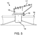
- Fig. 5 shows a pivot joint 13 comprising a bottom part 14 and an upper part 15.
- the bottom part and the upper part are forming together the pivot joint in which preferably the bottom part acts as a housing in which a shaft-like part of the upper part is sliding bearing-mounted.
- a suitable lubrication and a necessary amount bearing members are arranged in the housing for enabling pivoting the joint manually.
- Preferably lubrication nipples are arranged in a side of the housing.
- a plastic bearing sleeve may be arranged between the housing of the bottom part and the shaft of the upper part.
- the manual pivoting of the side conveyor can be made easier instead of or additionally to a pivoting force which is directed directly to the side conveyor.
- a sliding bearing bushing can be arranged between the housing of the bottom part and the shaft of the upper part, and a first axis of symmetry of the sliding bearing bushing which is defined by outer sliding surfaces of the sliding bearing bushing, and a second axis of symmetry of the sliding bearing bushing which is defined by inner sliding surfaces of the sliding bearing bushing, are in an angled position relative to each other, and the sliding bearing bushing is pivotable from outside the pivot joint.
- Such a sliding bearing bushing equipped with a pivoting axis having an inclined direction in relation to vertical direction can be equipped with a pivot lever for the operator.
- the bottom part 14 of the pivot joint is equipped with a fastening member 16 through which the bottom part is attached to the frame 2, for example, to a rear beam of the frame.
- the fastening member 16 is preferably a cantilever beam with plate structure which is attached by welding to the frame of the processing apparatus.
- the upper part 15 of the pivot joint is equipped with a mounting bed 17 to which the side conveyor 4 is attached.
- An inclination of a mounting surface of the mounting bed 17 relative to a support surface (earth surface) of the processing apparatus is preferably selected such that a frame structure of the side conveyor manufactured of linear profiles can simply be mounted on the mounting bed. In this way, one can stick by a minor amount of parts to be manufactured and assembled and one can save in manufacturing costs of the side conveyor.
- the side conveyor 4 can be locked in its pivoting direction to one or several operating positions and, if necessary, to a transportation position.
- a locking of the operating position is implemented, for example, by a locking pin 18 which is arranged in connection with the pivot joint 13. In locking positions, the locking pin 18 passes through holes or corresponding locking forms for the locking pin which act together, formed in the upper part 15 and bottom part 14 of the pivot joint. The operator can pivot and lock the side conveyor in different positions fast and safe without lifting devices.
- a transportation position of the side conveyor 4 is illustrated with Fig. 4 where the The side conveyor is pivoted in the direction of the processing apparatus 1.
- the side conveyor 4 is under the frame 2 of the processing apparatus in the transportation position.
- the outer dimensions of the processing apparatus do not increase at least substantially when the side conveyor is in the transportation position. Width of the processing apparatus has not necessary to be increased when the processing apparatus is put in the transportation position, and a minimal lengthening of the processing apparatus is not so detrimental as broadening.
- the side conveyor can be arranged to discharge also in the direction of the processing apparatus (backwards).
- the side conveyor In the transportation position, the side conveyor can be locked in the pivoting direction mechanically by means of the locking pin 18 but also other ways of locking can be used.
- Fig. 3 shows alternative locking devices for holding the side conveyor 4 in place in the transportation position.
- An advantageous way is to lock the side conveyor to the frame of the processing apparatus. Then, the frame bears a part of the free end of the side conveyor what indeed is not necessary in all embodiments.
- the side conveyor can be locked to the frame of the processing apparatus, for example, by means of the rear wing 7 of the feed hopper which rear wing is attached to the rear part 2' of the frame.
- the rear wing 7 is pivoted downwards in a transportation position for the processing apparatus not being overly high for transportation.
- the side conveyor 4, pivoted in direction of the rear wing can be locked by means of a suitable locking member 19 (for example, a hook) which is arranged in the rear wing 7.
- a locking shape 20 can be made in the rear wing such that the side conveyor 4 is locked in the transportation position when the rear wing is in downward position.
- a detachable and attachable fastening member 21 (for example, a threaded rod, a rigging screw, a chain) can be arranged between the rear part 2' of the frame and the side conveyor, which rear part extends above the side conveyor when the side conveyor is pivoted in the direction of the frame.
- a projection of the frame covers the side conveyor which is directed backwards. Additionally, the frame 2 provides under the rear part 2' a sufficient high free space for pivoting the side conveyor from one side to another side and backwards. Simultaneously, the frame is suitable high for mounting the feeder directly onto the rear part 2' of the frame without a separate auxiliary frame, what further makes the structure solution of the processing apparatus cost effective.
Landscapes
- Engineering & Computer Science (AREA)
- Mechanical Engineering (AREA)
- Food Science & Technology (AREA)
- Disintegrating Or Milling (AREA)
- Crushing And Grinding (AREA)
- Body Structure For Vehicles (AREA)
- Apparatuses For Bulk Treatment Of Fruits And Vegetables And Apparatuses For Preparing Feeds (AREA)
Description
- The invention relates to a movable processing apparatus which is suitable for mineral material processing. Particularly, though not exclusively, the invention relates to a movable processing apparatus which comprises a side conveyor apparatus and which is suitable for crushing, pre-screening, screening and/or conveying further mineral material.
- Such a movable processing apparatus is known for example from
DE102008060459 A1 . - Rock is gained from the earth for crushing by exploding or excavating. Rock can also be natural and gravel or construction waste. Mobile processing apparatuses (for example, crushing apparatuses) and stationary crushing applications are used in material processing (for example, crushing). An excavator or wheeled loader, for example, loads the material to be processed into the crusher's feed hopper from where the material to be processed ends up in a feeder which feeds the rock material, for example, in a jaw of a crusher or the feeder moves the rock material towards the crusher. A desired material, for example, fine material can be directed through the feeder to a side conveyor that this material does not result in further processing, for example, crushing. A usual location of the side conveyor is under the feeder where selected material can drop. Material directed past the further process is conveyed aside the processing apparatus by means of the side conveyor, for example, in a pile.
- In movable crushing apparatuses, for example, the side conveyor forms during transportation an obstacle which broadens the crushing apparatus and which has to be located, at least in road traffic, in a narrower space than an operating position of the side conveyor. Usually, the side conveyor is folded at a side of the machine for the time of the transportation, for example, hydraulically upwards in a vertical position. The conveyor is then, for example, of a model which is foldable at a region of a conveyor belt. Another option is to transport the side conveyor loosely.
- When a discharge direction of the side conveyor is desired to be changed to another side of a machine the side conveyor is released completely from fixing points, for example, by opening and fixing a bolt attachment of the side conveyor. Hydraulic hoses are detached, the side conveyor is lifted away from an opening in a side plate of the machine, transported to the other side of the machine and mounted again. An alternative in machines of today is that a sidedness of the side conveyor is not changeable.
- Hydraulic cylinders and joints are used in a structure of the side conveyor which is foldable at the side the crushing apparatus which enable locating the side conveyor at a side of the crushing apparatus. This structure is complicated, expensive and fault-sensitive. Both the transportation of the side conveyor loosely and the changing of the side are time consuming. A lifting device and sufficiently lifting aid has to be on the scene. Lifting work is a safety risk and requires several operators. Hydraulic hoses and electric cables must also be detached both when transported separately and when the side is changed which causes safety risks to personnel and environment.
- An object of the invention is to provide a movable processing apparatus for mineral material in connection with which problems related to known side conveyors can be avoided or at least reduced.
- According to the invention, which is defined by the appended claims, there is provided a movable processing apparatus for mineral material processing which comprises a movable frame and a side conveyor which is attached to the frame, and the movable processing apparatus comprises a pivot joint for the side conveyor which pivot joint is attached between the side conveyor and the frame, and the side conveyor is pivotable horizontally around the pivot joint to one or more operating positions at least on one side of the processing apparatus and to a transportation position.
- Preferably the side conveyor is pivotable to the transportation position from at least one side of the frame in direction of the frame such that a transportation width of the processing apparatus is not exceeded.
- The transportation width is preferably a transportation width of a vehicle which is transported in road traffic without an abnormal transport permit. Usually, the movable processing apparatuses are dimensioned at their broadest point (for example, frame, tracks or wheels) inside this transportation width.
- Preferably the side conveyor is pivotable to a first side of the frame and to a second side of the frame and to operating positions in a pivoting sector between the first side and the second side.
- Preferably the horizontally pivoting sector of the side conveyor is 180 degrees.
- Preferably the pivot joint comprises a bottom part which is attached to the frame and an upper part which is bearing-mounted to the bottom part in which the upper part the side conveyor is attached. Preferably the bottom part of the pivot joint comprises a housing and the upper part comprises a shaft which is sliding bearing-mounted to the housing. Preferably a sliding bearing bushing is arranged between the housing of the bottom part and the shaft of the upper part, and a first axis of symmetry of the sliding bearing bushing which is defined by outer sliding surfaces of the sliding bearing bushing and a second axis of symmetry of the sliding bearing bushing which is defined by inner sliding surfaces of the sliding bearing bushing are in an angled position relative to each other and the sliding bearing bushing is pivotable from outside the pivot joint.
- Preferably the upper part of the pivot joint comprises an upwards inclined mounting bed for the side conveyor.
- Preferably the side conveyor comprises a side conveyor frame which is assembled of linear profiles.
- Preferably the transportation position of the side conveyor is under the frame of the processing apparatus.
- A locking of the side conveyor in the horizontal pivoting direction may be arranged by means of a locking pin or a locking latch to be arranged between the bottom part and the upper part of the pivot joint, which locking pin or locking latch is fixable in a locking position and openable from the locking position.
- The processing apparatus may be equipped with a locking device which is arranged between a rear part of the frame and a discharge end of the side conveyor.
- The side conveyor can be pivoted manually around the pivot joint to different positions. If desired, the side conveyor can be directed to any operating direction in the pivoting sector of 180 degrees from the first side to the second side of the processing apparatus. The side conveyor can be pivoted to operating positions to both sides of the processing apparatus. The side conveyor can be locked in an operating position mechanically in a simple way, for example, by means of the locking pin or the locking latch which is arranged in connection with the pivot joint. The operator may pivot the side conveyor and lock the side conveyor in a pivoted position quickly and safely without lifting aid.
- The side conveyor can be pivoted in the transportation position in the direction of the frame of the processing apparatus. The side conveyor can be pivoted in the transportation position under the frame of the processing apparatus. In the transportation position, the side conveyor can be locked in the pivoted direction mechanically, for example, by means of the locking pin which is arranged in connection with the pivot joint. Additionally or alternatively (for example, when the processing apparatus is transported in the road traffic), the operator can lock the side conveyor to the frame of the processing apparatus. A preferable way is to lock the side conveyor by means of a rear wing of a feed hopper which is arranged in the frame of the processing apparatus. The side conveyor may be attached to the frame of the processing apparatus, for example, at its discharge end by the rear wing of the feed hopper or another locking device which is arranged in the frame of the processing apparatus.
- The pivotable side conveyor is functionally better, cheaper and more safe than known solutions. The pivoting solution of the side conveyor is a simple mechanical structure working with muscular force. As a particular advantage can be seen the pivoting of the side conveyor to different positions and a putting in transportation condition without hydraulic actuators. Hoses of hydraulics moving a conveying base of the side conveyor such as an endless belt can be all the time coupled. Also electric cables must not be detached. The side conveyor must not be detached from the processing apparatus for the putting in transportation condition, for the transportation or for the changing of the side. No lifting devices or other tools are needed for pivoting or the transportation of the side conveyor. One operator can fast change the side or put in transportation condition the side conveyor. Safety can be enhanced because lifting work and detaching of the hydraulic hoses are not needed. In some known side conveyor solutions, tightening and positioning of the conveyor belt is needed in connection with the putting in transportation condition what may be avoided in solutions according to the invention.
- The side conveyor may be pivoted momentary away from its operating position and returned back to the operating position. The side conveyor may be pivoted, for example, aside out of the way of a pile when it is desired to get the material away as efficient as possible with a wheeled loader.
- Also during use of the processing apparatus, the side conveyor may be pivoted in a protected state away from its operating position if it is not desired to operate the side conveyor. Additionally, during the transportation the side conveyor does not take space around the movable processing apparatus or at a working site. Different embodiments of the present invention will be illustrated or have been illustrated only in combination with one or some aspects of the invention. A person skilled in the art understands, that any embodiment of one aspect of the invention may be applied in the same aspect of the invention and in other aspects alone or as a combination with other embodiments.
- The invention will be described, by way of example, with reference to the accompanying drawings, in which:
-
Fig. 1 shows a movable mineral material processing apparatus according to a preferable embodiment comprising a side conveyor which can be pivoted from one side to another side of the processing apparatus; -
Fig. 2 shows the processing apparatus ofFig. 1 illustrated in a rear view from the direction of an arrow A ofFig. 1 and the side conveyor is pivoted at a side of the processing apparatus; -
Fig. 3 shows the processing apparatus ofFig. 1 illustrated in a side view and the side conveyor is pivoted backwards under a frame of the processing apparatus; -
Fig. 4 shows a pivoting region of the side conveyor of the processing apparatus ofFig. 1 ; and -
Fig. 5 shows a pivot joint of a side conveyor according to a preferable embodiment. - In the following description, like numbers denote like elements. It should be appreciated that the illustrated drawings are not entirely in scale, and that the drawings mainly serve the purpose of illustrating embodiments of the invention.
-
Figs. 1 to 4 show a movable mineralmaterial processing apparatus 1 comprising aframe 2. The processing apparatus comprisestracks 3, attached to the frame, for moving the processing apparatus and aside conveyor 4 which can be pivoted from a side to another side of the processing apparatus. The processing apparatus can be equipped with, for example, mineral material screening, conveying and/or crushing means (not shown in the figures). The crushing means may comprise, for example, a cone, a gyratory or an impact crusher. - A movable or mobile processing apparatus may also be movable on wheels, skids or legs. An alternative for moving the processing apparatus is forming the frame of the processing apparatus as a base having wheels which is towable by a vehicle.
- In
Fig. 1 , afeed hopper 5 is arranged in a rear part 2' of theframe 2 through which the material to be processed is received in the processing apparatus.Wings front part 9 of the feed hopper. The feed hopper comprises afirst side wing 6, arear wing 7 and asecond side wing 8 which are attached to theframe 2 through supports 10. The supports 10 are equipped with pivoting joints 10' for folding the side wings and the rear wing downwards to sides of theprocessing apparatus 1 during transportation and storage, for example. When thewings feed hopper 5 are folded, the feeder for the material to be processed can be mounted on theframe 2. The feeder can be put in operating position by folding up the wings of the feed hopper in the operating position. Mineral material screening, conveying and/or crushing means can be located on the frame next to the feeder. - Desired material, for example, fine material can be directed via the feeder or through the feeder to drop via a
material guide 11 to abelt 12 or a corresponding endless conveying base of theside conveyor 4 that this material does not result in further processing. A starting end of theside conveyor 4 is preferably located under the feeder. - The
side conveyor 4 can be pivoted from one side to another side of theprocessing apparatus 1. A pivot joint 13 is arranged in theprocessing apparatus 1 for the side conveyor by means of which the side conveyor is attached to theframe 2. The side conveyor can be pivoted, if necessary, manually around the pivot joint in different positions. The side conveyor can be directed, if necessary, in any direction in a pivoting sector 4' of 180 degrees from a first side to a second side of the processing apparatus (Fig. 4 ). The side conveyor can be pivoted in the pivoting sector 4' between operating positions and a transportation position. - Simplest the side conveyor can be pivoted to one side of the processing apparatus to an operating position. Preferably the side conveyor can be pivoted to both sides of the processing apparatus to operating positions. The side conveyor can be arranged in an operating position in any direction in a region of the pivoting sector 4'.
-
Fig. 5 shows a pivot joint 13 comprising abottom part 14 and anupper part 15. The bottom part and the upper part are forming together the pivot joint in which preferably the bottom part acts as a housing in which a shaft-like part of the upper part is sliding bearing-mounted. A suitable lubrication and a necessary amount bearing members are arranged in the housing for enabling pivoting the joint manually. Preferably lubrication nipples are arranged in a side of the housing. A plastic bearing sleeve may be arranged between the housing of the bottom part and the shaft of the upper part. - According to some embodiments the manual pivoting of the side conveyor can be made easier instead of or additionally to a pivoting force which is directed directly to the side conveyor. A sliding bearing bushing can be arranged between the housing of the bottom part and the shaft of the upper part, and a first axis of symmetry of the sliding bearing bushing which is defined by outer sliding surfaces of the sliding bearing bushing, and a second axis of symmetry of the sliding bearing bushing which is defined by inner sliding surfaces of the sliding bearing bushing, are in an angled position relative to each other, and the sliding bearing bushing is pivotable from outside the pivot joint. Such a sliding bearing bushing equipped with a pivoting axis having an inclined direction in relation to vertical direction can be equipped with a pivot lever for the operator.
- The
bottom part 14 of the pivot joint is equipped with afastening member 16 through which the bottom part is attached to theframe 2, for example, to a rear beam of the frame. Thefastening member 16 is preferably a cantilever beam with plate structure which is attached by welding to the frame of the processing apparatus. Theupper part 15 of the pivot joint is equipped with a mountingbed 17 to which theside conveyor 4 is attached. An inclination of a mounting surface of the mountingbed 17 relative to a support surface (earth surface) of the processing apparatus is preferably selected such that a frame structure of the side conveyor manufactured of linear profiles can simply be mounted on the mounting bed. In this way, one can stick by a minor amount of parts to be manufactured and assembled and one can save in manufacturing costs of the side conveyor. - The
side conveyor 4 can be locked in its pivoting direction to one or several operating positions and, if necessary, to a transportation position. A locking of the operating position is implemented, for example, by a lockingpin 18 which is arranged in connection with the pivot joint 13. In locking positions, the lockingpin 18 passes through holes or corresponding locking forms for the locking pin which act together, formed in theupper part 15 andbottom part 14 of the pivot joint. The operator can pivot and lock the side conveyor in different positions fast and safe without lifting devices. - A transportation position of the
side conveyor 4 is illustrated withFig. 4 where the The side conveyor is pivoted in the direction of theprocessing apparatus 1. Theside conveyor 4 is under theframe 2 of the processing apparatus in the transportation position. Thus, the outer dimensions of the processing apparatus do not increase at least substantially when the side conveyor is in the transportation position. Width of the processing apparatus has not necessary to be increased when the processing apparatus is put in the transportation position, and a minimal lengthening of the processing apparatus is not so detrimental as broadening. Naturally, the side conveyor can be arranged to discharge also in the direction of the processing apparatus (backwards). In the transportation position, the side conveyor can be locked in the pivoting direction mechanically by means of the lockingpin 18 but also other ways of locking can be used. -
Fig. 3 shows alternative locking devices for holding theside conveyor 4 in place in the transportation position. An advantageous way is to lock the side conveyor to the frame of the processing apparatus. Then, the frame bears a part of the free end of the side conveyor what indeed is not necessary in all embodiments. The side conveyor can be locked to the frame of the processing apparatus, for example, by means of therear wing 7 of the feed hopper which rear wing is attached to the rear part 2' of the frame. Therear wing 7 is pivoted downwards in a transportation position for the processing apparatus not being overly high for transportation. Theside conveyor 4, pivoted in direction of the rear wing, can be locked by means of a suitable locking member 19 (for example, a hook) which is arranged in therear wing 7. A lockingshape 20 can be made in the rear wing such that theside conveyor 4 is locked in the transportation position when the rear wing is in downward position. A detachable and attachable fastening member 21 (for example, a threaded rod, a rigging screw, a chain) can be arranged between the rear part 2' of the frame and the side conveyor, which rear part extends above the side conveyor when the side conveyor is pivoted in the direction of the frame. - Design of the rear part 2' of the
frame 2 and combination of the pivot joint 13 which enables the pivoting of theside conveyor 14 with a suitable shaped rear part 2' are bearing a significant role in the free pivotability of the side conveyor. Next to thetracks 3, the rear part 2' opens backwards in a highly upwards inclined direction when theprocessing apparatus 1 is seen in a side view. At the side of the frame of the processing apparatus there are no horizontal beams of known frames directed horizontally backwards (next to the tracks), and through an opening above these horizontal beams, formed by the horizontal beams, the detachable and attachable known side conveyor is mounted inside the frame under the feeder. Thus, one has been able to make theframe 2 inexpensive. In some embodiments, a projection of the frame, seen in a top view, covers the side conveyor which is directed backwards. Additionally, theframe 2 provides under the rear part 2' a sufficient high free space for pivoting the side conveyor from one side to another side and backwards. Simultaneously, the frame is suitable high for mounting the feeder directly onto the rear part 2' of the frame without a separate auxiliary frame, what further makes the structure solution of the processing apparatus cost effective. - The foregoing description provides non-limiting examples of some embodiments of the invention. It is clear to a person skilled in the art that the invention is not restricted to details presented, but that the invention can be implemented in other equivalent means. Some of the features of the above-disclosed embodiments may be used to advantage without the use of other features.
- As such, the foregoing description shall be considered as merely illustrative of the principles of the invention, and not in limitation thereof. Hence, the scope of the invention is only restricted by the appended patent claims.
Claims (14)
- A movable processing apparatus (1) for mineral material processing, comprising:a movable frame (2);a side conveyor (4) attached to the frame;a pivot joint (13) for the side conveyor which pivot joint is attached between the side conveyor (4) and the frame (2); characterized in thatthe side conveyor is pivotable horizontally around the pivot joint to one or more operating positions at least on one side of the processing apparatus and to a protected state in a transportation position under the frame.
- The movable processing apparatus according to claim 1, characterized in that the side conveyor can be pivoted between transport and operating positions without detaching of hydraulic hoses.
- The movable processing apparatus according to claim 1 or 2, characterized in that the side conveyor (4) is pivotable to the transportation position from at least one side of the frame (2) in direction of the frame such that a transportation width of the processing apparatus is not exceeded.
- The movable processing apparatus according to any of preceding claims, characterized in that the side conveyor (4) is pivotable to a first side of the frame (2) and to a second side of the frame and to operating positions in a pivoting sector (4') between the first side and the second side.
- The movable processing apparatus according to any of preceding claims, characterized in that the horizontally pivoting sector (4') of the side conveyor (4) is 180 degrees.
- The movable processing apparatus according to any of preceding claims, characterized in that the pivot joint (13) comprises a bottom part (14) which is attached to the frame (2) and an upper part (15) which is bearing-mounted to the bottom part in which the upper part the side conveyor is attached.
- The movable processing apparatus according to claim 6, characterized in that the bottom part (14) of the pivot joint comprises a housing and the upper part (15) comprises a shaft which is sliding bearing-mounted to the housing.
- The movable processing apparatus according to claim 6 or 7, characterized in that the upper part (15) of the pivot joint (13) comprises an upwards inclined mounting bed (17) for the side conveyor (4).
- The movable processing apparatus according to any of preceding claims, characterized in that the side conveyor (4) comprises a side conveyor frame which is assembled of linear profiles.
- The movable processing apparatus according to any of preceding claims, characterized in that the transportation position of the side conveyor (4) is under the frame (2, 2') of the processing apparatus.
- The movable processing apparatus according to any of preceding claims, characterized in that a locking of the side conveyor (4) in the horizontal pivoting direction is arranged by means of a locking pin (18) or a locking latch to be arranged between the bottom part (14) and the upper part (15) of the pivot joint (13), which locking pin or locking latch is fixable in a locking position and openable from the locking position.
- The movable processing apparatus according to any of preceding claims, characterized in that the processing apparatus (1) is equipped with a locking device (19, 20, 21) which is arranged between a rear part (2') of the frame (2) and a discharge end of the side conveyor (4).
- The movable processing apparatus according to any of preceding claims, characterized in that the processing apparatus (1) is equipped with any of mineral material screening and crushing means.
- The movable processing apparatus according to any of preceding claims, characterized in that the side conveyor is manually pivotable around the pivot joint.
Priority Applications (1)
| Application Number | Priority Date | Filing Date | Title |
|---|---|---|---|
| EP15182626.0A EP2977107B1 (en) | 2011-02-15 | 2011-02-15 | Movable processing apparatus for mineral material processing |
Applications Claiming Priority (3)
| Application Number | Priority Date | Filing Date | Title |
|---|---|---|---|
| EP15182626.0A EP2977107B1 (en) | 2011-02-15 | 2011-02-15 | Movable processing apparatus for mineral material processing |
| PCT/FI2011/050139 WO2012110679A1 (en) | 2011-02-15 | 2011-02-15 | Movable process device for mineral material processing |
| EP11711110.4A EP2675564A1 (en) | 2011-02-15 | 2011-02-15 | Movable process device for mineral material processing |
Related Parent Applications (1)
| Application Number | Title | Priority Date | Filing Date |
|---|---|---|---|
| EP11711110.4A Division EP2675564A1 (en) | 2011-02-15 | 2011-02-15 | Movable process device for mineral material processing |
Publications (2)
| Publication Number | Publication Date |
|---|---|
| EP2977107A1 EP2977107A1 (en) | 2016-01-27 |
| EP2977107B1 true EP2977107B1 (en) | 2017-06-14 |
Family
ID=44626684
Family Applications (3)
| Application Number | Title | Priority Date | Filing Date |
|---|---|---|---|
| EP11711110.4A Pending EP2675564A1 (en) | 2011-02-15 | 2011-02-15 | Movable process device for mineral material processing |
| EP15182626.0A Revoked EP2977107B1 (en) | 2011-02-15 | 2011-02-15 | Movable processing apparatus for mineral material processing |
| EP11723490.6A Active EP2675565B1 (en) | 2011-02-15 | 2011-03-30 | Movable processing apparatus for mineral material processing and frame for processing apparatus |
Family Applications Before (1)
| Application Number | Title | Priority Date | Filing Date |
|---|---|---|---|
| EP11711110.4A Pending EP2675564A1 (en) | 2011-02-15 | 2011-02-15 | Movable process device for mineral material processing |
Family Applications After (1)
| Application Number | Title | Priority Date | Filing Date |
|---|---|---|---|
| EP11723490.6A Active EP2675565B1 (en) | 2011-02-15 | 2011-03-30 | Movable processing apparatus for mineral material processing and frame for processing apparatus |
Country Status (10)
| Country | Link |
|---|---|
| US (3) | US9061836B2 (en) |
| EP (3) | EP2675564A1 (en) |
| JP (2) | JP5822954B2 (en) |
| CN (2) | CN103415347B (en) |
| AU (1) | AU2011359056B2 (en) |
| BR (1) | BR112013020831B1 (en) |
| PL (1) | PL2675565T3 (en) |
| RU (1) | RU2562386C2 (en) |
| WO (2) | WO2012110679A1 (en) |
| ZA (1) | ZA201305430B (en) |
Cited By (1)
| Publication number | Priority date | Publication date | Assignee | Title |
|---|---|---|---|---|
| EP4344785A1 (en) | 2022-09-29 | 2024-04-03 | SBM Mineral Processing GmbH | Processing device |
Families Citing this family (9)
| Publication number | Priority date | Publication date | Assignee | Title |
|---|---|---|---|---|
| GB201118144D0 (en) * | 2011-10-20 | 2011-11-30 | Terex Gb Ltd | Foldable conveyor support structure with wraparound capability |
| GB2507766B (en) * | 2012-11-08 | 2018-02-14 | Terex Gb Ltd | Folding mechanism |
| GB2515445B (en) * | 2013-01-18 | 2017-05-24 | Terex Gb Ltd | Material processing apparatus with deployable feed conveyor |
| EP2837585B1 (en) | 2013-08-14 | 2015-12-30 | Sandvik Intellectual Property AB | Main frame for mobile bulk processing apparatus |
| EP2837583B1 (en) * | 2013-08-14 | 2015-10-14 | Sandvik Intellectual Property AB | Mobile bulk material processing apparatus with slewing conveyor |
| CN206367803U (en) * | 2016-11-01 | 2017-08-01 | 合肥鑫晟光电科技有限公司 | Transferred product device |
| US10513294B2 (en) | 2017-11-07 | 2019-12-24 | Cnh Industrial America Llc | Boxed plate construction frame with plates of varying thicknesses |
| DE102020130981A1 (en) | 2020-11-24 | 2022-05-25 | Kleemann Gmbh | processing plant |
| CN112774818B (en) * | 2020-12-29 | 2022-03-25 | 新沂市铭达玻璃有限公司 | Waste recovery device for glass manufacturing |
Citations (8)
| Publication number | Priority date | Publication date | Assignee | Title |
|---|---|---|---|---|
| US2564020A (en) | 1950-02-13 | 1951-08-14 | William F Mengel | Vehicle for hauling and dispensing material |
| DE2303984A1 (en) | 1973-01-27 | 1974-08-01 | Gerhard Muesch | UNLOADING CONVEYOR BELT |
| DE2758435A1 (en) | 1977-01-25 | 1978-07-27 | Vretstorp Verken Ab | WAGONS FOR THE TRANSPORTATION AND SPREADING OF BALLAST AND EMBROIDERY MATERIAL FOR THE MAINTENANCE OF RAILWAYS |
| EP0419423A1 (en) | 1989-09-22 | 1991-03-27 | Franz Plasser Bahnbaumaschinen-Industriegesellschaft m.b.H. | A railway car for the transportation of debris |
| EP0480321A1 (en) | 1990-10-09 | 1992-04-15 | Franz Plasser Bahnbaumaschinen-Industriegesellschaft m.b.H. | Wagon for transporting ballast |
| DE19625438A1 (en) | 1996-06-25 | 1998-01-02 | Breuer Hans Michael | Mobile preparation machine, in particular screening machine, for ballast ballast in the railway system |
| WO2004087324A1 (en) | 2003-04-02 | 2004-10-14 | ThyssenKrupp Fördertechnik GmbH | Comminution device |
| US20080210145A1 (en) | 2007-02-15 | 2008-09-04 | Unverferth Manufacturing Company Inc. | Seed carrier with pivoting conveyor |
Family Cites Families (29)
| Publication number | Priority date | Publication date | Assignee | Title |
|---|---|---|---|---|
| US2707062A (en) * | 1952-11-03 | 1955-04-26 | Dean A Parker | Hydraulic chain lift trailer drawbar |
| US3151884A (en) * | 1962-05-08 | 1964-10-06 | Felburn John Phil | Low-bed trailer with hinged gooseneck for unloading purposes |
| US3863783A (en) * | 1971-12-16 | 1975-02-04 | Symons Corp | Distributing conveyor system for a rotary concrete mixing or other truck |
| SU1235530A1 (en) * | 1985-01-14 | 1986-06-07 | Предприятие П/Я Г-4781 | Self-propelled crusher |
| US4618307A (en) * | 1985-02-22 | 1986-10-21 | Kress Corporation | Scrap bucket carrier |
| JPH01317840A (en) | 1988-06-17 | 1989-12-22 | Hamana Jidosha Kogyo Kk | Trailer and connection device for tracting trailer |
| US5040849A (en) * | 1989-08-03 | 1991-08-20 | Kress Corporation | Elevatable dump box carrier with tilt frame and rear latch |
| US5324061A (en) * | 1993-07-09 | 1994-06-28 | Lay Larry L | Gooseneck hitch apparatus |
| US5564205A (en) * | 1995-06-01 | 1996-10-15 | Astec Industries, Inc. | Excavating machine with stowable discharge conveyor |
| JP3756558B2 (en) | 1995-09-25 | 2006-03-15 | 泰壽 玉光 | Lump crushing plant car |
| US6186338B1 (en) * | 1996-05-03 | 2001-02-13 | Patrick Joseph Douglas | Self-propelled material-processing apparatus |
| JP3547963B2 (en) | 1996-12-24 | 2004-07-28 | 新キャタピラー三菱株式会社 | Construction, lighting and work machines |
| US5797615A (en) * | 1996-12-31 | 1998-08-25 | Harley Murray, Inc. | Heavy equipment trailer with adjustable tower |
| GB9930161D0 (en) | 1999-12-22 | 2000-02-09 | Parker Plant Ltd | Improved aggregate processing plant |
| JP2004188389A (en) | 2002-12-13 | 2004-07-08 | Komatsu Ltd | Crusher and assembly method for the crusher |
| JP4255805B2 (en) | 2003-11-05 | 2009-04-15 | 日立建機株式会社 | Recycled product production auxiliary machine |
| FI117670B (en) * | 2004-07-07 | 2007-01-15 | Metso Minerals Tampere Oy | Filling hopper, method of locking walls of a filling hopper, and locking means |
| JP2006110406A (en) * | 2004-10-12 | 2006-04-27 | Shin Caterpillar Mitsubishi Ltd | Mobile crusher |
| FI119921B (en) * | 2004-11-10 | 2009-05-15 | Metso Minerals Oy | Mobile mineral processing unit body and multifunction clamp |
| CN100586573C (en) | 2005-08-29 | 2010-02-03 | 株式会社小松制作所 | Jaw crusher and self-traveling crusher |
| WO2009077640A1 (en) * | 2007-12-19 | 2009-06-25 | Metso Minerals Inc. | A method for moving a material processing device, a device for processing mineral material, and a frame for a processing device |
| US7832767B2 (en) * | 2008-01-04 | 2010-11-16 | Mac Trailer Manufacturing, Inc. | Aluminum flatbed with unique front connection |
| DE102008060459A1 (en) | 2008-12-05 | 2010-06-10 | ThyssenKrupp Fördertechnik GmbH | Mobile crushing plant |
| CN201603597U (en) * | 2010-01-07 | 2010-10-13 | 赵大力 | Moveable crushing station |
| WO2012064541A1 (en) * | 2010-11-08 | 2012-05-18 | Flsmidth A/S | Mobile sizing station |
| US8662460B2 (en) * | 2010-12-03 | 2014-03-04 | Deere & Company | Weight adapter bracket |
| US8573915B2 (en) * | 2011-03-31 | 2013-11-05 | Dakota Manufacturing Company, Inc. | Trailer |
| US8627947B2 (en) * | 2011-09-06 | 2014-01-14 | Sakundiak Equipment Ltd. | Feed auger lift assembly for an agricultural conveyor |
| GB2502144B (en) * | 2012-05-18 | 2017-05-17 | Terex Gb Ltd | Folding mechanism with locking function |
-
2011
- 2011-02-15 RU RU2013139999/13A patent/RU2562386C2/en active
- 2011-02-15 WO PCT/FI2011/050139 patent/WO2012110679A1/en active Application Filing
- 2011-02-15 BR BR112013020831-7A patent/BR112013020831B1/en active IP Right Grant
- 2011-02-15 EP EP11711110.4A patent/EP2675564A1/en active Pending
- 2011-02-15 EP EP15182626.0A patent/EP2977107B1/en not_active Revoked
- 2011-02-15 AU AU2011359056A patent/AU2011359056B2/en active Active
- 2011-02-15 CN CN201180067605.7A patent/CN103415347B/en active Active
- 2011-02-15 US US13/985,703 patent/US9061836B2/en active Active
- 2011-02-15 JP JP2013552990A patent/JP5822954B2/en active Active
- 2011-03-30 EP EP11723490.6A patent/EP2675565B1/en active Active
- 2011-03-30 WO PCT/FI2011/050272 patent/WO2012110683A1/en active Application Filing
- 2011-03-30 JP JP2013552991A patent/JP5815747B2/en active Active
- 2011-03-30 US US13/984,220 patent/US9193537B2/en active Active
- 2011-03-30 PL PL11723490T patent/PL2675565T3/en unknown
- 2011-03-30 CN CN201180066435.0A patent/CN103402644B/en active Active
-
2013
- 2013-07-18 ZA ZA2013/05430A patent/ZA201305430B/en unknown
-
2015
- 2015-05-14 US US14/711,880 patent/US9725249B2/en active Active
Patent Citations (8)
| Publication number | Priority date | Publication date | Assignee | Title |
|---|---|---|---|---|
| US2564020A (en) | 1950-02-13 | 1951-08-14 | William F Mengel | Vehicle for hauling and dispensing material |
| DE2303984A1 (en) | 1973-01-27 | 1974-08-01 | Gerhard Muesch | UNLOADING CONVEYOR BELT |
| DE2758435A1 (en) | 1977-01-25 | 1978-07-27 | Vretstorp Verken Ab | WAGONS FOR THE TRANSPORTATION AND SPREADING OF BALLAST AND EMBROIDERY MATERIAL FOR THE MAINTENANCE OF RAILWAYS |
| EP0419423A1 (en) | 1989-09-22 | 1991-03-27 | Franz Plasser Bahnbaumaschinen-Industriegesellschaft m.b.H. | A railway car for the transportation of debris |
| EP0480321A1 (en) | 1990-10-09 | 1992-04-15 | Franz Plasser Bahnbaumaschinen-Industriegesellschaft m.b.H. | Wagon for transporting ballast |
| DE19625438A1 (en) | 1996-06-25 | 1998-01-02 | Breuer Hans Michael | Mobile preparation machine, in particular screening machine, for ballast ballast in the railway system |
| WO2004087324A1 (en) | 2003-04-02 | 2004-10-14 | ThyssenKrupp Fördertechnik GmbH | Comminution device |
| US20080210145A1 (en) | 2007-02-15 | 2008-09-04 | Unverferth Manufacturing Company Inc. | Seed carrier with pivoting conveyor |
Cited By (1)
| Publication number | Priority date | Publication date | Assignee | Title |
|---|---|---|---|---|
| EP4344785A1 (en) | 2022-09-29 | 2024-04-03 | SBM Mineral Processing GmbH | Processing device |
Also Published As
| Publication number | Publication date |
|---|---|
| US20150307285A1 (en) | 2015-10-29 |
| BR112013020831B1 (en) | 2020-11-24 |
| EP2675564A1 (en) | 2013-12-25 |
| US9193537B2 (en) | 2015-11-24 |
| EP2675565B1 (en) | 2019-06-26 |
| US20130313400A1 (en) | 2013-11-28 |
| CN103415347A (en) | 2013-11-27 |
| JP5815747B2 (en) | 2015-11-17 |
| EP2675565A1 (en) | 2013-12-25 |
| WO2012110679A1 (en) | 2012-08-23 |
| AU2011359056A1 (en) | 2013-08-01 |
| JP2014511297A (en) | 2014-05-15 |
| AU2011359056B2 (en) | 2016-10-13 |
| JP5822954B2 (en) | 2015-11-25 |
| US9725249B2 (en) | 2017-08-08 |
| CN103415347B (en) | 2015-02-18 |
| US20140048382A1 (en) | 2014-02-20 |
| JP2014506532A (en) | 2014-03-17 |
| ZA201305430B (en) | 2014-08-27 |
| PL2675565T3 (en) | 2020-01-31 |
| US9061836B2 (en) | 2015-06-23 |
| AU2011359056A2 (en) | 2013-10-31 |
| CN103402644A (en) | 2013-11-20 |
| RU2013139999A (en) | 2015-03-27 |
| RU2562386C2 (en) | 2015-09-10 |
| EP2977107A1 (en) | 2016-01-27 |
| WO2012110683A1 (en) | 2012-08-23 |
| BR112013020831A2 (en) | 2018-07-10 |
| CN103402644B (en) | 2015-11-25 |
Similar Documents
| Publication | Publication Date | Title |
|---|---|---|
| EP2977107B1 (en) | Movable processing apparatus for mineral material processing | |
| EP1320421B1 (en) | Bulk material processing apparatus | |
| EP3102511B1 (en) | Conveyor body and mobile mineral material processing plant | |
| CN105592928B (en) | Mineral material processing equipment and the method for operating process equipment | |
| CN104093501B (en) | Material processing plant | |
| US8783443B2 (en) | Material processing plant | |
| EP2837585B1 (en) | Main frame for mobile bulk processing apparatus | |
| EP2664492B1 (en) | Folding mechanism with locking function | |
| AU2013399880B2 (en) | A mineral material processing plant and a method for operating a processing plant | |
| US6405874B1 (en) | Mobile material handling apparatus with lowerable track set | |
| WO2004085071A1 (en) | A crushing plant |
Legal Events
| Date | Code | Title | Description |
|---|---|---|---|
| PUAI | Public reference made under article 153(3) epc to a published international application that has entered the european phase |
Free format text: ORIGINAL CODE: 0009012 |
|
| AC | Divisional application: reference to earlier application |
Ref document number: 2675564 Country of ref document: EP Kind code of ref document: P |
|
| AK | Designated contracting states |
Kind code of ref document: A1 Designated state(s): AL AT BE BG CH CY CZ DE DK EE ES FI FR GB GR HR HU IE IS IT LI LT LU LV MC MK MT NL NO PL PT RO RS SE SI SK SM TR |
|
| 17P | Request for examination filed |
Effective date: 20160606 |
|
| RBV | Designated contracting states (corrected) |
Designated state(s): AL AT BE BG CH CY CZ DE DK EE ES FI FR GB GR HR HU IE IS IT LI LT LU LV MC MK MT NL NO PL PT RO RS SE SI SK SM TR |
|
| RIC1 | Information provided on ipc code assigned before grant |
Ipc: B65G 41/00 20060101ALI20161212BHEP Ipc: B02C 21/02 20060101AFI20161212BHEP Ipc: B65G 37/00 20060101ALI20161212BHEP Ipc: B65G 47/20 20060101ALI20161212BHEP |
|
| GRAP | Despatch of communication of intention to grant a patent |
Free format text: ORIGINAL CODE: EPIDOSNIGR1 |
|
| STAA | Information on the status of an ep patent application or granted ep patent |
Free format text: STATUS: GRANT OF PATENT IS INTENDED |
|
| INTG | Intention to grant announced |
Effective date: 20170120 |
|
| RAP1 | Party data changed (applicant data changed or rights of an application transferred) |
Owner name: METSO MINERALS, INC. |
|
| GRAS | Grant fee paid |
Free format text: ORIGINAL CODE: EPIDOSNIGR3 |
|
| GRAA | (expected) grant |
Free format text: ORIGINAL CODE: 0009210 |
|
| STAA | Information on the status of an ep patent application or granted ep patent |
Free format text: STATUS: THE PATENT HAS BEEN GRANTED |
|
| AC | Divisional application: reference to earlier application |
Ref document number: 2675564 Country of ref document: EP Kind code of ref document: P |
|
| AK | Designated contracting states |
Kind code of ref document: B1 Designated state(s): AL AT BE BG CH CY CZ DE DK EE ES FI FR GB GR HR HU IE IS IT LI LT LU LV MC MK MT NL NO PL PT RO RS SE SI SK SM TR |
|
| REG | Reference to a national code |
Ref country code: GB Ref legal event code: FG4D |
|
| REG | Reference to a national code |
Ref country code: CH Ref legal event code: EP Ref country code: AT Ref legal event code: REF Ref document number: 900448 Country of ref document: AT Kind code of ref document: T Effective date: 20170615 |
|
| REG | Reference to a national code |
Ref country code: IE Ref legal event code: FG4D |
|
| REG | Reference to a national code |
Ref country code: DE Ref legal event code: R096 Ref document number: 602011038840 Country of ref document: DE |
|
| REG | Reference to a national code |
Ref country code: SE Ref legal event code: TRGR |
|
| REG | Reference to a national code |
Ref country code: NL Ref legal event code: MP Effective date: 20170614 |
|
| REG | Reference to a national code |
Ref country code: LT Ref legal event code: MG4D |
|
| REG | Reference to a national code |
Ref country code: NO Ref legal event code: T2 Effective date: 20170614 |
|
| PG25 | Lapsed in a contracting state [announced via postgrant information from national office to epo] |
Ref country code: GR Free format text: LAPSE BECAUSE OF FAILURE TO SUBMIT A TRANSLATION OF THE DESCRIPTION OR TO PAY THE FEE WITHIN THE PRESCRIBED TIME-LIMIT Effective date: 20170915 Ref country code: HR Free format text: LAPSE BECAUSE OF FAILURE TO SUBMIT A TRANSLATION OF THE DESCRIPTION OR TO PAY THE FEE WITHIN THE PRESCRIBED TIME-LIMIT Effective date: 20170614 Ref country code: LT Free format text: LAPSE BECAUSE OF FAILURE TO SUBMIT A TRANSLATION OF THE DESCRIPTION OR TO PAY THE FEE WITHIN THE PRESCRIBED TIME-LIMIT Effective date: 20170614 |
|
| PG25 | Lapsed in a contracting state [announced via postgrant information from national office to epo] |
Ref country code: BG Free format text: LAPSE BECAUSE OF FAILURE TO SUBMIT A TRANSLATION OF THE DESCRIPTION OR TO PAY THE FEE WITHIN THE PRESCRIBED TIME-LIMIT Effective date: 20170914 Ref country code: RS Free format text: LAPSE BECAUSE OF FAILURE TO SUBMIT A TRANSLATION OF THE DESCRIPTION OR TO PAY THE FEE WITHIN THE PRESCRIBED TIME-LIMIT Effective date: 20170614 Ref country code: NL Free format text: LAPSE BECAUSE OF FAILURE TO SUBMIT A TRANSLATION OF THE DESCRIPTION OR TO PAY THE FEE WITHIN THE PRESCRIBED TIME-LIMIT Effective date: 20170614 Ref country code: LV Free format text: LAPSE BECAUSE OF FAILURE TO SUBMIT A TRANSLATION OF THE DESCRIPTION OR TO PAY THE FEE WITHIN THE PRESCRIBED TIME-LIMIT Effective date: 20170614 |
|
| PG25 | Lapsed in a contracting state [announced via postgrant information from national office to epo] |
Ref country code: SK Free format text: LAPSE BECAUSE OF FAILURE TO SUBMIT A TRANSLATION OF THE DESCRIPTION OR TO PAY THE FEE WITHIN THE PRESCRIBED TIME-LIMIT Effective date: 20170614 Ref country code: CZ Free format text: LAPSE BECAUSE OF FAILURE TO SUBMIT A TRANSLATION OF THE DESCRIPTION OR TO PAY THE FEE WITHIN THE PRESCRIBED TIME-LIMIT Effective date: 20170614 Ref country code: RO Free format text: LAPSE BECAUSE OF FAILURE TO SUBMIT A TRANSLATION OF THE DESCRIPTION OR TO PAY THE FEE WITHIN THE PRESCRIBED TIME-LIMIT Effective date: 20170614 Ref country code: EE Free format text: LAPSE BECAUSE OF FAILURE TO SUBMIT A TRANSLATION OF THE DESCRIPTION OR TO PAY THE FEE WITHIN THE PRESCRIBED TIME-LIMIT Effective date: 20170614 |
|
| REG | Reference to a national code |
Ref country code: FR Ref legal event code: PLFP Year of fee payment: 8 |
|
| PG25 | Lapsed in a contracting state [announced via postgrant information from national office to epo] |
Ref country code: ES Free format text: LAPSE BECAUSE OF FAILURE TO SUBMIT A TRANSLATION OF THE DESCRIPTION OR TO PAY THE FEE WITHIN THE PRESCRIBED TIME-LIMIT Effective date: 20170614 Ref country code: IS Free format text: LAPSE BECAUSE OF FAILURE TO SUBMIT A TRANSLATION OF THE DESCRIPTION OR TO PAY THE FEE WITHIN THE PRESCRIBED TIME-LIMIT Effective date: 20171014 Ref country code: SM Free format text: LAPSE BECAUSE OF FAILURE TO SUBMIT A TRANSLATION OF THE DESCRIPTION OR TO PAY THE FEE WITHIN THE PRESCRIBED TIME-LIMIT Effective date: 20170614 Ref country code: PL Free format text: LAPSE BECAUSE OF FAILURE TO SUBMIT A TRANSLATION OF THE DESCRIPTION OR TO PAY THE FEE WITHIN THE PRESCRIBED TIME-LIMIT Effective date: 20170614 |
|
| REG | Reference to a national code |
Ref country code: DE Ref legal event code: R026 Ref document number: 602011038840 Country of ref document: DE |
|
| PLBI | Opposition filed |
Free format text: ORIGINAL CODE: 0009260 |
|
| PLAX | Notice of opposition and request to file observation + time limit sent |
Free format text: ORIGINAL CODE: EPIDOSNOBS2 |
|
| 26 | Opposition filed |
Opponent name: THYSSENKRUPP INDUSTRIAL SOLUTIONS AG Effective date: 20180306 |
|
| PG25 | Lapsed in a contracting state [announced via postgrant information from national office to epo] |
Ref country code: DK Free format text: LAPSE BECAUSE OF FAILURE TO SUBMIT A TRANSLATION OF THE DESCRIPTION OR TO PAY THE FEE WITHIN THE PRESCRIBED TIME-LIMIT Effective date: 20170614 |
|
| PLAB | Opposition data, opponent's data or that of the opponent's representative modified |
Free format text: ORIGINAL CODE: 0009299OPPO |
|
| PLBB | Reply of patent proprietor to notice(s) of opposition received |
Free format text: ORIGINAL CODE: EPIDOSNOBS3 |
|
| PG25 | Lapsed in a contracting state [announced via postgrant information from national office to epo] |
Ref country code: SI Free format text: LAPSE BECAUSE OF FAILURE TO SUBMIT A TRANSLATION OF THE DESCRIPTION OR TO PAY THE FEE WITHIN THE PRESCRIBED TIME-LIMIT Effective date: 20170614 |
|
| R26 | Opposition filed (corrected) |
Opponent name: THYSSENKRUPP INDUSTRIAL SOLUTIONS AG Effective date: 20180717 |
|
| REG | Reference to a national code |
Ref country code: CH Ref legal event code: PL |
|
| PG25 | Lapsed in a contracting state [announced via postgrant information from national office to epo] |
Ref country code: MC Free format text: LAPSE BECAUSE OF FAILURE TO SUBMIT A TRANSLATION OF THE DESCRIPTION OR TO PAY THE FEE WITHIN THE PRESCRIBED TIME-LIMIT Effective date: 20170614 |
|
| REG | Reference to a national code |
Ref country code: IE Ref legal event code: MM4A |
|
| PG25 | Lapsed in a contracting state [announced via postgrant information from national office to epo] |
Ref country code: LU Free format text: LAPSE BECAUSE OF NON-PAYMENT OF DUE FEES Effective date: 20180215 Ref country code: LI Free format text: LAPSE BECAUSE OF NON-PAYMENT OF DUE FEES Effective date: 20180228 Ref country code: CH Free format text: LAPSE BECAUSE OF NON-PAYMENT OF DUE FEES Effective date: 20180228 |
|
| PG25 | Lapsed in a contracting state [announced via postgrant information from national office to epo] |
Ref country code: IE Free format text: LAPSE BECAUSE OF NON-PAYMENT OF DUE FEES Effective date: 20180215 |
|
| APAH | Appeal reference modified |
Free format text: ORIGINAL CODE: EPIDOSCREFNO |
|
| APBM | Appeal reference recorded |
Free format text: ORIGINAL CODE: EPIDOSNREFNO |
|
| APBP | Date of receipt of notice of appeal recorded |
Free format text: ORIGINAL CODE: EPIDOSNNOA2O |
|
| PG25 | Lapsed in a contracting state [announced via postgrant information from national office to epo] |
Ref country code: MT Free format text: LAPSE BECAUSE OF NON-PAYMENT OF DUE FEES Effective date: 20180215 |
|
| APBQ | Date of receipt of statement of grounds of appeal recorded |
Free format text: ORIGINAL CODE: EPIDOSNNOA3O |
|
| PG25 | Lapsed in a contracting state [announced via postgrant information from national office to epo] |
Ref country code: TR Free format text: LAPSE BECAUSE OF FAILURE TO SUBMIT A TRANSLATION OF THE DESCRIPTION OR TO PAY THE FEE WITHIN THE PRESCRIBED TIME-LIMIT Effective date: 20170614 |
|
| PG25 | Lapsed in a contracting state [announced via postgrant information from national office to epo] |
Ref country code: PT Free format text: LAPSE BECAUSE OF FAILURE TO SUBMIT A TRANSLATION OF THE DESCRIPTION OR TO PAY THE FEE WITHIN THE PRESCRIBED TIME-LIMIT Effective date: 20170614 |
|
| PG25 | Lapsed in a contracting state [announced via postgrant information from national office to epo] |
Ref country code: CY Free format text: LAPSE BECAUSE OF FAILURE TO SUBMIT A TRANSLATION OF THE DESCRIPTION OR TO PAY THE FEE WITHIN THE PRESCRIBED TIME-LIMIT Effective date: 20170614 Ref country code: MK Free format text: LAPSE BECAUSE OF NON-PAYMENT OF DUE FEES Effective date: 20170614 Ref country code: HU Free format text: LAPSE BECAUSE OF FAILURE TO SUBMIT A TRANSLATION OF THE DESCRIPTION OR TO PAY THE FEE WITHIN THE PRESCRIBED TIME-LIMIT; INVALID AB INITIO Effective date: 20110215 |
|
| PG25 | Lapsed in a contracting state [announced via postgrant information from national office to epo] |
Ref country code: AL Free format text: LAPSE BECAUSE OF FAILURE TO SUBMIT A TRANSLATION OF THE DESCRIPTION OR TO PAY THE FEE WITHIN THE PRESCRIBED TIME-LIMIT Effective date: 20170614 |
|
| REG | Reference to a national code |
Ref country code: AT Ref legal event code: UEP Ref document number: 900448 Country of ref document: AT Kind code of ref document: T Effective date: 20170614 |
|
| PGFP | Annual fee paid to national office [announced via postgrant information from national office to epo] |
Ref country code: DE Payment date: 20220105 Year of fee payment: 12 |
|
| PGFP | Annual fee paid to national office [announced via postgrant information from national office to epo] |
Ref country code: IT Payment date: 20220111 Year of fee payment: 12 |
|
| REG | Reference to a national code |
Ref country code: NO Ref legal event code: CHAD Owner name: METSO OUTOTEC FINLAND OY, FI |
|
| APBU | Appeal procedure closed |
Free format text: ORIGINAL CODE: EPIDOSNNOA9O |
|
| REG | Reference to a national code |
Ref country code: DE Ref legal event code: R103 Ref document number: 602011038840 Country of ref document: DE Ref country code: DE Ref legal event code: R064 Ref document number: 602011038840 Country of ref document: DE |
|
| REG | Reference to a national code |
Ref country code: BE Ref legal event code: HC Owner name: METSO OUTOTEC FINLAND OY; FI Free format text: DETAILS ASSIGNMENT: CHANGE OF OWNER(S), CHANGE OF OWNER(S) NAME; FORMER OWNER NAME: METSO MINERALS, INC. Effective date: 20221108 |
|
| REG | Reference to a national code |
Ref country code: AT Ref legal event code: HC Ref document number: 900448 Country of ref document: AT Kind code of ref document: T Owner name: METSO OUTOTEC FINLAND OY, FI Effective date: 20221122 |
|
| RDAF | Communication despatched that patent is revoked |
Free format text: ORIGINAL CODE: EPIDOSNREV1 |
|
| STAA | Information on the status of an ep patent application or granted ep patent |
Free format text: STATUS: PATENT REVOKED |
|
| RDAG | Patent revoked |
Free format text: ORIGINAL CODE: 0009271 |
|
| REG | Reference to a national code |
Ref country code: CH Ref legal event code: PL |
|
| 27W | Patent revoked |
Effective date: 20221213 |
|
| GBPR | Gb: patent revoked under art. 102 of the ep convention designating the uk as contracting state |
Effective date: 20221213 |
|
| PGFP | Annual fee paid to national office [announced via postgrant information from national office to epo] |
Ref country code: NO Payment date: 20230208 Year of fee payment: 13 Ref country code: FR Payment date: 20230123 Year of fee payment: 13 Ref country code: FI Payment date: 20230220 Year of fee payment: 13 Ref country code: AT Payment date: 20230125 Year of fee payment: 13 |
|
| REG | Reference to a national code |
Ref country code: DE Ref legal event code: R081 Ref document number: 602011038840 Country of ref document: DE Owner name: METSO MINERALS, INC., FI Free format text: FORMER OWNER: METSO MINERALS, INC., HELSINKI, FI |
|
| PGFP | Annual fee paid to national office [announced via postgrant information from national office to epo] |
Ref country code: SE Payment date: 20230110 Year of fee payment: 13 Ref country code: GB Payment date: 20230105 Year of fee payment: 13 Ref country code: BE Payment date: 20230117 Year of fee payment: 13 |
|
| REG | Reference to a national code |
Ref country code: AT Ref legal event code: MA03 Ref document number: 900448 Country of ref document: AT Kind code of ref document: T Effective date: 20221213 |
|
| REG | Reference to a national code |
Ref country code: SE Ref legal event code: ECNC |