EP1628852B1 - Streckentrennerisolator - Google Patents
Streckentrennerisolator Download PDFInfo
- Publication number
- EP1628852B1 EP1628852B1 EP04735026A EP04735026A EP1628852B1 EP 1628852 B1 EP1628852 B1 EP 1628852B1 EP 04735026 A EP04735026 A EP 04735026A EP 04735026 A EP04735026 A EP 04735026A EP 1628852 B1 EP1628852 B1 EP 1628852B1
- Authority
- EP
- European Patent Office
- Prior art keywords
- neutral section
- section insulator
- insulator
- neutral
- conductor line
- Prior art date
- Legal status (The legal status is an assumption and is not a legal conclusion. Google has not performed a legal analysis and makes no representation as to the accuracy of the status listed.)
- Expired - Lifetime
Links
- 239000012212 insulator Substances 0.000 title claims abstract description 127
- 230000007935 neutral effect Effects 0.000 claims abstract description 122
- 239000004020 conductor Substances 0.000 claims abstract description 56
- 239000003365 glass fiber Substances 0.000 claims description 5
- 239000011521 glass Substances 0.000 claims description 4
- 239000004810 polytetrafluoroethylene Substances 0.000 claims description 4
- 229920001343 polytetrafluoroethylene Polymers 0.000 claims description 4
- 239000004593 Epoxy Substances 0.000 claims description 3
- 239000002131 composite material Substances 0.000 claims description 3
- 239000002783 friction material Substances 0.000 claims description 3
- 239000011324 bead Substances 0.000 claims description 2
- 239000003822 epoxy resin Substances 0.000 claims description 2
- 238000000465 moulding Methods 0.000 claims description 2
- 229920000647 polyepoxide Polymers 0.000 claims description 2
- 230000002787 reinforcement Effects 0.000 claims description 2
- 239000004065 semiconductor Substances 0.000 claims description 2
- RYGMFSIKBFXOCR-UHFFFAOYSA-N Copper Chemical compound [Cu] RYGMFSIKBFXOCR-UHFFFAOYSA-N 0.000 description 7
- 229910052802 copper Inorganic materials 0.000 description 7
- 239000010949 copper Substances 0.000 description 7
- 230000004888 barrier function Effects 0.000 description 6
- 230000007613 environmental effect Effects 0.000 description 4
- 230000002411 adverse Effects 0.000 description 2
- 230000008901 benefit Effects 0.000 description 2
- 238000009833 condensation Methods 0.000 description 2
- 230000005494 condensation Effects 0.000 description 2
- 230000005684 electric field Effects 0.000 description 2
- 150000003839 salts Chemical class 0.000 description 2
- 230000035939 shock Effects 0.000 description 2
- 230000009471 action Effects 0.000 description 1
- 239000000853 adhesive Substances 0.000 description 1
- 230000001070 adhesive effect Effects 0.000 description 1
- 238000005452 bending Methods 0.000 description 1
- 230000008859 change Effects 0.000 description 1
- 239000003795 chemical substances by application Substances 0.000 description 1
- 238000011109 contamination Methods 0.000 description 1
- 230000000593 degrading effect Effects 0.000 description 1
- 230000000694 effects Effects 0.000 description 1
- 239000012530 fluid Substances 0.000 description 1
- 238000009434 installation Methods 0.000 description 1
- 239000011810 insulating material Substances 0.000 description 1
- 238000009413 insulation Methods 0.000 description 1
- 238000002955 isolation Methods 0.000 description 1
- 238000012423 maintenance Methods 0.000 description 1
- 239000000463 material Substances 0.000 description 1
- 239000003973 paint Substances 0.000 description 1
- 230000001105 regulatory effect Effects 0.000 description 1
- -1 salt ions Chemical class 0.000 description 1
- 230000007480 spreading Effects 0.000 description 1
- 239000000758 substrate Substances 0.000 description 1
- 230000001360 synchronised effect Effects 0.000 description 1
Images




Classifications
-
- B—PERFORMING OPERATIONS; TRANSPORTING
- B60—VEHICLES IN GENERAL
- B60M—POWER SUPPLY LINES, AND DEVICES ALONG RAILS, FOR ELECTRICALLY- PROPELLED VEHICLES
- B60M1/00—Power supply lines for contact with collector on vehicle
- B60M1/12—Trolley lines; Accessories therefor
- B60M1/18—Section insulators; Section switches
Definitions
- the present invention relates to a neutral section insulator for use in conjunction with railway overhead conductor lines.
- Electric trains are powered through overhead copper conductor lines, the power being conveyed via a pantograph attached to the roof of the train.
- the conductor lines are usually powered by 25kV AC supplied from power stations along the route of the lines.
- a peak-to-peak difference of up to 50kV AC can occur where two power supplies meet along the length of a conductor line. It is important to ensure that the pantograph does not register the difference in power supplies as otherwise a large electrical load would be placed on it, which could damage it and other electrical equipment in the train.
- it is impractical to synchronise the power stations they are normally isolated from each other by the provision of an assembly known as a neutral section insulator on each conductor line.
- pantograph does not detect the presence of the neutral section insulator on the conductor lines as, apart from electrical loading, it would then also be subject to variable reaction forces, which would be conveyed to the train to cause "bumping".
- the neutral section insulators that are currently on the market include those provided by Siemens GmbH, Arthur Flury AG and Furrer & Frey AG.
- the neutral section insulator of Siemens GmbH consisting of two insulator rods mounted on plates with copper conductors being clamped thereto, is mechanically quite different from the conductors and increases the scope of shock loading on the pantograph.
- the height of the neutral section insulator can be adjusted relative to the copper conductors in order to align them as closely as possible in the vertical plane, the catenary member that is used for such adjustment makes the neutral section insulator assembly more bulky, increases its structural and mechanical difference from the conductor lines, and complicates its installation.
- This neutral section insulator is provided in this neutral section insulator to channel the power dissipation that occurs if the pantograph registers the difference in power supplies.
- it is not particularly effective in this role, as often sparks are seen to form where the pantograph attaches to the neutral section insulator.
- this neutral section insulator is expensive, wears quickly (it needs to be replaced roughly every eight months), and requires monthly maintenance to turn the insulator sections (which wear out by virtue of point contact with the pantograph).
- GB-A-1378751 discloses a neutral section insulator comprising an insulator body to isolate the ends of the conductor line from each other, wherein the neutral axis of the neutral section insulator is such that when the neutral section insulator is in use the neutral axis is aligned closely with the neutral axis of the conductors on its either side and the height of the insulator body is chosen so that the stiffness and the dynamic mass of the neutral section insulator closely match those of the conductors on its either side in both the vertical and horizontal planes.
- a neutral section insulator for use with an overhead railway power supply line, which neutral section insulator is disposed between the ends of two separated sections of conductor line of the power supply when in use, the neutral section insulator comprising an insulator body for isolating the ends of said conductor line sections from each other; wherein the neutral section insulator is designed such that, when the neutral section insulator is in use, (a) its neutral axis is aligned closely with the neutral axis of the conductor line sections on its either side and (b) the stiffness and the dynamic mass of the neutral section insulator closely match those of the conductor line sections on its either side in both the vertical and horizontal planes; characterised in that the insulator body comprises a single, integral body, the profile of which is shaped so as to achieve the characteristic (a) and the height of which is chosen so as to achieve the characteristic (b).
- the structural and mechanical profile of a neutral section insulator embodying the present invention is constructed to closely correspond with that of railway overhead copper conductor lines in order to minimise the scope of being registered by a pantograph, this being achieved by closely aligning the neutral axes (median bending line) of the neutral section insulator and the conductors on its either side, and by closely matching the stiffness and the dynamic mass of the neutral section insulator and the conductors in both the vertical and horizontal planes.
- An embodiment of the present invention provides a continuous running surface to the pantograph that is both coplanar with the conductors on its either side (so that the pantograph is not subject to shock loading) and narrow (since misalignment with the pantograph would cause a severe twisting action in the neutral section insulator), and also provides the advantage that the drag imposed by the neutral section insulator on the pantograph is equal to, or less than, that exerted on it by the conductors.
- an embodiment of the present invention provides isolation over a distance in excess of 1.5m, even when the pantograph (which is 0.2m in width) attaches to the neutral section insulator and effectively increases its length to about 1.7m.
- An embodiment of the present invention is capable of withstanding the 15kN loads, which are hung every few hundred metres along the length of the conductor lines in order to provide tension, without degrading.
- An embodiment of the present invention provides all the above-discussed advantages in adverse environmental conditions such as rain, snow, contamination, etc.
- Figure 1 shows a neutral section insulator 1 embodying the present invention.
- the neutral section insulator 1 includes an elongate insulator body 10 moulded from an insulating material such as a glass-fibre reinforced epoxy composite with a 45% glass fraction.
- the outer surface of the insulator body 10 can be chemically treated or coated with a paint to improve its shedding ability and be generally resilient in adverse environmental conditions.
- the neutral section insulator 1 also contains a connection member 2 by way of which it connects to adjacent conductor ends.
- the connection member 2 is a U-shaped copper member embedded within the insulator body 10 with its legs 3, 4 (hereinafter referred to as conductor tails) protruding therefrom and lying adjacent to the conductors on either side of the insulator body 10.
- One of the conductor tails 4 is connected to an end of the conductor line using conventional splices, for example, whilst the other conductor tail 3, although usually redundant, can be used as an arcing hom if required. If there is any wear on the conductor section into which the neutral section insulator is being fitted, the end face of the connecting conductor tail 4 can be filed accordingly so that a step height change between the neutral section insulator, and the conductor section can be avoided.
- connection member 2 used in an embodiment of the present invention is shown in more detail in Figure 4 in which Figure 4a is a perspective view, Figure 4b is a front view and Figure 4c is a side view.
- pegs 5 are provided on the surface of the connection member 2, equally spaced apart and so as to protrude from the outer surfaces of the conductor tails 3, 4 at corresponding positions. The pegs 5 are driven through the surfaces of the conductor tails 3, 4, before the connection member 2 is placed in the insulator mould. When the mould sets, the pegs 5 remain firmly lodged in the insulator body walls, thus ensuring that the connection member 2 is held strongly within.
- the radii of curvature e and f are 23mm and 11.19mm, respectively.
- the profile of the neutral section insulator 1 is matched with those of the copper conductors with which it is to be used on its either side by aligning the neutral axes of the neutral section insulator 1 and the copper conductors. This is achieved by designing the profile of the neutral section insulator 1 such that its neutral axis is as low as reasonably practical, such as, for example, to lie only 12mm above the neutral axis of adjacent conductors. Furthermore, the height of the insulator body is increased so that the stiffness of the neutral section insulator 1 matches that of the conductors on its either side in both the vertical and horizontal planes.
- a neutral section insulator 1 embodying the present invention can be designed as shown in Figure 5, in which Figure 5a is a front view of the neutral section insulator 1, Figures 5b, 5c and 5d are cross-sections respectively taken on line A-A, line B-B, and line C-C, and Figure 5e shows an outer view of one face of the neutral section insulator 1. As most clearly seen from Figures 5b to 5d, when in use, the profile of the neutral section insulator 1 would be streamlined with those of the conductors lying adjacent to it.
- the angle i of the sidewalls of the neutral section insulator 1 is 12°.
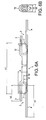
- Figure 6a and 6b show respective front and side views of an embodiment of the present invention.
- two rails 6, 7 are embedded in the running surface of the neutral section insulator 1.
- these rails 6, 7 lie parallel to the conductor at each end of the neutral section insulator 1, they provide a continuous surface against which the pantograph can run.
- the rails pose less frictional drag to the pantograph compared to when it traverses the length of the conductors, thus helping to reduce wear of the pantograph and insulator body 10.
- the wear characteristics of the rails can be improved by incorporating glass beads in the PTFE.
- Figure 8 shows an embodiment of the present invention with a modified surface.
- a semiconductor tape is attached to the spine of the neutral section insulator 1, which has the effect of spreading the excess charge associated with arcing by conducting it along the length of the neutral section insulator 1.
- electrical plates (barriers) 11 or “sheds” are attached to the spine of the neutral section insulator 1 in order to increase the effective electrical path length of the neutral section insulator 1.
- the barriers are made from epoxy resin with chopped strand glass fibre reinforcement. However, they could be made of any other appropriate material that is waterproof and non-conducting.
- the electrical barriers in an embodiment of the present invention are semi-circular in shape with slots where they are attached to the spine of the neutral section insulator 1.
- the barriers are spaced, and not necessarily periodically, at a distance of 100mm or greater. It has been found that, for the voltages that the neutral section insulator 1 is subjected to when in use, a barrier spacing of less than 100mm becomes transparent to an electric field, which will "jump" this gap.
- a trace heater is incorporated into the moulding of the insulator body 10 in an embodiment of the present invention.
- the function of the trace heater is best understood when the neutral section insulator 1 is subjected to a "salt fog" test. This test involves exposing the neutral section insulator 1 to a salt intensive vapour cloud in a specialised chamber so as to evaluate its discharge properties.
- the heater is used to increase the temperature of the neutral section insulator 1 above the dewpoint temperature of the condensing vapour cloud so that it does not condense on the outer surface of the neutral section insulator 1, or if it does, it evaporates quickly.
- a trace heater it is ensured that no electrical discharge occurs from its surface due to the presence of a condensation film thereon when the neutral section insulator heater element on a Kapton R strip.
- Temperature limiting resistors are formed on the printed substrate bearing the heater and are connected in series to the heater.
- the non-linear dependence of the resistance of these resistors on the ambient temperature drastically limits the current flowing therethrough at high ambient temperatures, thus allowing the temperature of the neutral section insulator 1 to be dynamically regulated and maintained at the same value in extreme environmental conditions.
- four such temperature limiting resistors are discretely formed along the length of the neutral section insulator 1, at equal intervals, so that the neutral section insulator 1 is maintained at the same temperature along its whole length.
- connection member 2 need not be U-shaped and can be any other appropriate shape.
- connection member 2 can be lodged within the insulator body via alternative means to the pegs 5 described hereinabove. If support is required in the mid-section of a neutral section insulator 1 embodying the present invention, the neutral section insulator 1 may be connected to an overhead catenary system using insulation droppers attached to the spine of the insulator 1 via adhesive pads.
Landscapes
- Engineering & Computer Science (AREA)
- Mechanical Engineering (AREA)
- Current-Collector Devices For Electrically Propelled Vehicles (AREA)
- Insulators (AREA)
- Linear Motors (AREA)
- Driving Mechanisms And Operating Circuits Of Arc-Extinguishing High-Tension Switches (AREA)
- Breakers (AREA)
- Circuit Breakers (AREA)
Claims (22)
- Neutraler Streckentrenner (1) zur Verwendung in einer Eisenbahn-Oberleitung, wobei der neutrale Streckentrenner (1) bei Gebrauch zwischen den Enden zweier getrennter Abschnitte der Stromschiene der Stromversorgung angeordnet ist, der neutrale Streckentrenner (1) einen Isolierkörper (10) umfasst zur Isolierung der Enden der Stromschienenabschnitte voneinander, der neutrale Streckentrenner (1) so gestaltet ist, dass im Einsatz (a) seine Schwerachse möglichst genau mit der Schwerachse der Stromschienenabschnitte auf seinen beiden Seiten ausgerichtet ist und (b) die Steifigkeit und die dynamische Masse des neutralen Streckentrenners (1) möglichst genau mit den entsprechenden Werten der Stromschienenabschnitte auf beiden Seiten übereinstimmen, sowohl in der vertikalen als auch in der horizontalen Richtung; dadurch gekennzeichnet, dass der Isolierkörper (10) ein einziger einstückiger Körper ist, dessen Querschnitt so gestaltet ist, dass er das Merkmal (a) erfüllt und dessen Höhe so gewählt ist, dass er das Merkmal (b) erfüllt.
- Neutraler Streckentrenner (1) nach Anspruch 1, wobei der Isolierkörper (10) aus einem glasfaserverstärkten Epoxid-Verbundwerkstoff besteht.
- Neutraler Streckentrenner (1) nach Anspruch 2, wobei der glasfaserverstärkte Epoxid-Verbundwerkstoff 45% Glasanteil enthält.
- Neutraler Streckentrenner (1) nach irgendeinem der vorstehenden Ansprüche, der ferner Verbindungsstäbe (2) umfasst zur Verbindung des neutralen Streckentrenners (1) mit den Enden der Stromschienenabschnitte.
- Neutraler Streckentrenner nach Anspruch 4, wobei die Verbindungsglieder (2) jeweils ein U-förmiger Stab mit zwei Armen (3, 4) ist, wobei die beiden Arme (3, 4) aus dem neutralen Streckentrenner (1) hervorstehen.
- Neutraler Streckentrenner nach Anspruch 5, wobei einer der beiden Arme (4) zur Verbindung des neutralen Streckentrenners (1) mit einem Ende des Stromschienenabschnitts verwendet wird.
- Neutraler Streckentrenner nach Anspruch 5 oder 6, wobei der andere der beiden Arme (3) als Schutzhorn dienen kann.
- Neutraler Streckentrenner nach irgendeinem der Ansprüche 4 bis 7, wobei Stifte (5) an der Außenfläche jedes Verbindungsstabs angebracht sind.
- Neutraler Streckentrenner nach irgendeinem der vorstehenden Ansprüche, der ferner ein Bauteil mit geringer Reibung umfasst zur Bereitstellung einer durchgehenden Lauffläche über den neutralen Streckentrenner (1) zwischen den Enden der Stromschienenabschnitte, wobei das Bauteil mit geringer Reibung auf der Unterseite des neutralen Streckentrenners (1) angeordnet ist und parallel zu den Enden der Stromschienenabschnitte liegt, wenn der neutrale Streckentrenner (1) im Einsatz ist.
- Neutraler Streckentrenner nach Anspruch 9, wobei das Bauteil mit geringer Reibung aus einem Material mit geringer Reibung besteht.
- Neutraler Streckentrenner nach Anspruch 9 oder 10, wobei Glasperlen in das Bauteil mit geringer Reibung eingearbeitet sind.
- Neutraler Streckentrenner nach irgendeinem der Ansprüche 9 bis 11, wobei das Material mit geringer Reibung PTFE ist.
- Neutraler Streckentrenner nach irgendeinem der Ansprüche 9 bis 12, wobei der neutrale Streckentrenner zwei Bauteile mit geringer Reibung aufweist, welche ein Schienenpaar (6, 7) bilden.
- Neutraler Streckentrenner nach irgendeinem der vorstehenden Ansprüche, wobei ein Halbleiterband am Rücken des neutralen Streckentrenners (1) befestigt ist.
- Neutraler Streckentrenner nach irgendeinem der vorstehenden Ansprüche, wobei elektrische Platten (11) am Rücken des neutralen Streckentrenners (1) befestigt sind.
- Neutraler Streckentrenner nach Anspruch 15, wobei die elektrischen Platten (11) jeweils aus Epoxidharz mit zerhackter Glasfaserverstärkung besteht.
- Neutraler Streckentrenner nach Anspruch 15 oder 16, wobei die Platten (11) in Abständen von 100mm oder mehr angeordnet sind.
- Neutraler Streckentrenner nach irgendeinem der Ansprüche 15 bis 17, wobei die Platten (11) teilweise kreisförmige Flächen besitzen.
- Neutraler Streckentrenner nach irgendeinem der vorstehenden Ansprüche, wobei die leitenden Enden des neutralen Streckentrenners (1) nach oben gewandt sind.
- Neutraler Streckentrenner nach irgendeinem der vorstehenden Ansprüche, wobei eine Heizvorrichtung in der Ausformung des Isolierkörpers (10) eingebaut ist.
- Neutraler Streckentrenner nach Anspruch 20, wobei die Heizvorrichtung eine elektrische Leistung von 150W besitzt.
- Neutraler Streckentrenner nach irgendeinem der Ansprüche 20 oder 21, wobei mindestens ein Temperaturbegrenzungswiderstand mit der Heizvorrichtung in Rehe geschaltet ist.
Applications Claiming Priority (3)
| Application Number | Priority Date | Filing Date | Title |
|---|---|---|---|
| GBGB0312831.1A GB0312831D0 (en) | 2003-06-04 | 2003-06-04 | Neutral section |
| GB0405412A GB2402373B (en) | 2003-06-04 | 2004-03-10 | Neutral section insulator |
| PCT/GB2004/002251 WO2004108469A1 (en) | 2003-06-04 | 2004-05-27 | Neutral section |
Publications (2)
| Publication Number | Publication Date |
|---|---|
| EP1628852A1 EP1628852A1 (de) | 2006-03-01 |
| EP1628852B1 true EP1628852B1 (de) | 2007-07-25 |
Family
ID=33512685
Family Applications (1)
| Application Number | Title | Priority Date | Filing Date |
|---|---|---|---|
| EP04735026A Expired - Lifetime EP1628852B1 (de) | 2003-06-04 | 2004-05-27 | Streckentrennerisolator |
Country Status (7)
| Country | Link |
|---|---|
| US (2) | US7552807B2 (de) |
| EP (1) | EP1628852B1 (de) |
| AT (1) | ATE367948T1 (de) |
| CA (1) | CA2527973A1 (de) |
| DE (1) | DE602004007798T2 (de) |
| NO (1) | NO20060014L (de) |
| WO (1) | WO2004108469A1 (de) |
Families Citing this family (3)
| Publication number | Priority date | Publication date | Assignee | Title |
|---|---|---|---|---|
| ES2246743B2 (es) * | 2005-10-06 | 2007-08-16 | Metro De Madrid, S.A. | Aislador de seccion para catenaria rigida. |
| JP5943458B2 (ja) * | 2011-10-17 | 2016-07-05 | 三和テッキ株式会社 | 電車線路用セクションインシュレータ及びその絶縁部材の防水カバー |
| CN107283869B (zh) * | 2017-07-31 | 2019-08-09 | 株洲时代新材料科技股份有限公司 | 一种接触网支撑装置的整体成型方法 |
Family Cites Families (16)
| Publication number | Priority date | Publication date | Assignee | Title |
|---|---|---|---|---|
| US560097A (en) * | 1896-05-12 | Trolley-wire and trolley therefor | ||
| US1868619A (en) * | 1929-02-11 | 1932-07-26 | George W Schroeder | Section insulator |
| US1940873A (en) * | 1932-04-12 | 1933-12-26 | Westinghouse Electric & Mfg Co | Trolley wire splicer |
| GB802046A (en) | 1956-01-13 | 1958-09-24 | British Insulated Callenders | Improvements relating to section insulators for contact wires of electric traction systems |
| DE1057164B (de) * | 1957-09-27 | 1959-05-14 | Licentia Gmbh | Lichtbogensicherer Streckentrenner |
| US3952848A (en) * | 1971-03-24 | 1976-04-27 | Bicc Limited | Section insulators of electric traction systems |
| GB1378751A (en) * | 1971-03-24 | 1974-12-27 | British Insulated Callenders | Electric insulators |
| GB1326071A (en) | 1971-04-19 | 1973-08-08 | British Insulated Callenders | Section insulators for use in overhead conductors and electrical traction systems |
| GB1502780A (en) * | 1974-12-31 | 1978-03-01 | Bicc Ltd | Insulated runner for use in overhead electric traction systems |
| GB1505083A (en) | 1974-12-31 | 1978-03-22 | Bicc Ltd | Overhead electric traction systems |
| DE2741547C2 (de) | 1977-09-15 | 1983-03-24 | Rosenthal Technik Ag, 8672 Selb | Streckentrennerisolator |
| JPS564637A (en) | 1979-06-26 | 1981-01-19 | Lion Corp | Antistatic resin composition having excellent nonstickness |
| US4406930A (en) * | 1980-11-13 | 1983-09-27 | Siemens Aktiengesellschaft | Trolley wire section insulator with two parallel insulating sliding strips |
| US4424889A (en) * | 1981-03-12 | 1984-01-10 | Hoeckele Max | Phase break-section insulator devices of high tensile strength |
| JPS584637A (ja) * | 1981-06-30 | 1983-01-11 | Matsushita Electric Works Ltd | ヒ−タ線付絶縁トロリ−線 |
| US5310047A (en) * | 1992-11-06 | 1994-05-10 | Valu Engineering, Inc. | Reversible conveyor return guide shoe |
-
2004
- 2004-05-27 DE DE602004007798T patent/DE602004007798T2/de not_active Expired - Lifetime
- 2004-05-27 EP EP04735026A patent/EP1628852B1/de not_active Expired - Lifetime
- 2004-05-27 AT AT04735026T patent/ATE367948T1/de not_active IP Right Cessation
- 2004-05-27 WO PCT/GB2004/002251 patent/WO2004108469A1/en not_active Ceased
- 2004-05-27 US US10/553,297 patent/US7552807B2/en not_active Expired - Fee Related
- 2004-05-27 CA CA002527973A patent/CA2527973A1/en not_active Abandoned
-
2006
- 2006-01-03 NO NO20060014A patent/NO20060014L/no not_active Application Discontinuation
-
2009
- 2009-05-21 US US12/470,124 patent/US7740117B2/en not_active Expired - Fee Related
Non-Patent Citations (1)
| Title |
|---|
| None * |
Also Published As
| Publication number | Publication date |
|---|---|
| EP1628852A1 (de) | 2006-03-01 |
| US7740117B2 (en) | 2010-06-22 |
| DE602004007798T2 (de) | 2007-12-06 |
| DE602004007798D1 (de) | 2007-09-06 |
| ATE367948T1 (de) | 2007-08-15 |
| WO2004108469A1 (en) | 2004-12-16 |
| NO20060014L (no) | 2006-01-03 |
| CA2527973A1 (en) | 2004-12-16 |
| US20060286875A1 (en) | 2006-12-21 |
| US7552807B2 (en) | 2009-06-30 |
| US20090223766A1 (en) | 2009-09-10 |
Similar Documents
| Publication | Publication Date | Title |
|---|---|---|
| US8203074B2 (en) | Messenger supported overhead cable for electrical transmission | |
| US11021080B2 (en) | Section insulator for an overhead contact line | |
| CN104114398B (zh) | 分段的集电器靴组件 | |
| EP3260326A1 (de) | Temperaturkompensationsvorrichtung für eine starre oberleitung | |
| US10651452B2 (en) | Connection assembly for a traction battery in particular for electric vehicles | |
| US6104010A (en) | Spring clamp for heater element | |
| GB2415176A (en) | Conductor rail for holding a contact wire | |
| US7740117B2 (en) | Neutral section insulator | |
| KR101746285B1 (ko) | 강체전차선용 지지클램프 | |
| US6264017B1 (en) | Multi-conductor power bar system and trolley therefor | |
| US20150298578A1 (en) | Rigid t-rail conductor system | |
| US2700705A (en) | Electrical duct and trolley collector | |
| ZA200509029B (en) | Neutral section | |
| CN102438855B (zh) | 架空线装置 | |
| EP2234233B1 (de) | Aufhängungsklemme | |
| US6206156B1 (en) | Section insulator for conductor rails | |
| US20120261164A1 (en) | Electric fence wire insulator | |
| CN106409444A (zh) | 防污秽的绝缘子 | |
| CN220615550U (zh) | 一种地铁出入段柔性非接触式分段绝缘器 | |
| US10593446B2 (en) | Apparatus for providing an arc diverter for covered overhead conductors and related assemblies and methods | |
| RU231974U1 (ru) | Соединитель рельсовый стыковой пружинный | |
| US3378651A (en) | Traveling electric power collector | |
| CN114172106B (zh) | 一种过桥装置 | |
| US4018315A (en) | Insulated runner for use in overhead electric traction systems | |
| KR200406068Y1 (ko) | 전차선로용 180밀리미터 대체용 폴리머 현수애자 |
Legal Events
| Date | Code | Title | Description |
|---|---|---|---|
| PUAI | Public reference made under article 153(3) epc to a published international application that has entered the european phase |
Free format text: ORIGINAL CODE: 0009012 |
|
| 17P | Request for examination filed |
Effective date: 20051102 |
|
| AK | Designated contracting states |
Kind code of ref document: A1 Designated state(s): AT BE BG CH CY CZ DE DK EE ES FI FR GB GR HU IE IT LI LU MC NL PL PT RO SE SI SK TR |
|
| DAX | Request for extension of the european patent (deleted) | ||
| GRAP | Despatch of communication of intention to grant a patent |
Free format text: ORIGINAL CODE: EPIDOSNIGR1 |
|
| GRAS | Grant fee paid |
Free format text: ORIGINAL CODE: EPIDOSNIGR3 |
|
| GRAA | (expected) grant |
Free format text: ORIGINAL CODE: 0009210 |
|
| AK | Designated contracting states |
Kind code of ref document: B1 Designated state(s): AT BE BG CH CY CZ DE DK EE ES FI FR GB GR HU IE IT LI LU MC NL PL PT RO SE SI SK TR |
|
| REG | Reference to a national code |
Ref country code: GB Ref legal event code: FG4D |
|
| RIN1 | Information on inventor provided before grant (corrected) |
Inventor name: SHRUBSALL, PETER RICKARD Inventor name: BOINTON, RICHARD GUY |
|
| REG | Reference to a national code |
Ref country code: CH Ref legal event code: NV Representative=s name: DR. LUSUARDI AG Ref country code: CH Ref legal event code: EP |
|
| REG | Reference to a national code |
Ref country code: IE Ref legal event code: FG4D |
|
| REF | Corresponds to: |
Ref document number: 602004007798 Country of ref document: DE Date of ref document: 20070906 Kind code of ref document: P |
|
| ET | Fr: translation filed | ||
| PG25 | Lapsed in a contracting state [announced via postgrant information from national office to epo] |
Ref country code: PT Free format text: LAPSE BECAUSE OF FAILURE TO SUBMIT A TRANSLATION OF THE DESCRIPTION OR TO PAY THE FEE WITHIN THE PRESCRIBED TIME-LIMIT Effective date: 20071226 Ref country code: ES Free format text: LAPSE BECAUSE OF FAILURE TO SUBMIT A TRANSLATION OF THE DESCRIPTION OR TO PAY THE FEE WITHIN THE PRESCRIBED TIME-LIMIT Effective date: 20071105 Ref country code: BG Free format text: LAPSE BECAUSE OF FAILURE TO SUBMIT A TRANSLATION OF THE DESCRIPTION OR TO PAY THE FEE WITHIN THE PRESCRIBED TIME-LIMIT Effective date: 20071025 Ref country code: NL Free format text: LAPSE BECAUSE OF FAILURE TO SUBMIT A TRANSLATION OF THE DESCRIPTION OR TO PAY THE FEE WITHIN THE PRESCRIBED TIME-LIMIT Effective date: 20070725 Ref country code: FI Free format text: LAPSE BECAUSE OF FAILURE TO SUBMIT A TRANSLATION OF THE DESCRIPTION OR TO PAY THE FEE WITHIN THE PRESCRIBED TIME-LIMIT Effective date: 20070725 |
|
| NLV1 | Nl: lapsed or annulled due to failure to fulfill the requirements of art. 29p and 29m of the patents act | ||
| PG25 | Lapsed in a contracting state [announced via postgrant information from national office to epo] |
Ref country code: PL Free format text: LAPSE BECAUSE OF FAILURE TO SUBMIT A TRANSLATION OF THE DESCRIPTION OR TO PAY THE FEE WITHIN THE PRESCRIBED TIME-LIMIT Effective date: 20070725 |
|
| PG25 | Lapsed in a contracting state [announced via postgrant information from national office to epo] |
Ref country code: DK Free format text: LAPSE BECAUSE OF FAILURE TO SUBMIT A TRANSLATION OF THE DESCRIPTION OR TO PAY THE FEE WITHIN THE PRESCRIBED TIME-LIMIT Effective date: 20070725 Ref country code: GR Free format text: LAPSE BECAUSE OF FAILURE TO SUBMIT A TRANSLATION OF THE DESCRIPTION OR TO PAY THE FEE WITHIN THE PRESCRIBED TIME-LIMIT Effective date: 20071026 |
|
| PLBI | Opposition filed |
Free format text: ORIGINAL CODE: 0009260 |
|
| PLAX | Notice of opposition and request to file observation + time limit sent |
Free format text: ORIGINAL CODE: EPIDOSNOBS2 |
|
| PG25 | Lapsed in a contracting state [announced via postgrant information from national office to epo] |
Ref country code: SK Free format text: LAPSE BECAUSE OF FAILURE TO SUBMIT A TRANSLATION OF THE DESCRIPTION OR TO PAY THE FEE WITHIN THE PRESCRIBED TIME-LIMIT Effective date: 20070725 |
|
| 26 | Opposition filed |
Opponent name: SIEMENS AG Effective date: 20080421 |
|
| PLAB | Opposition data, opponent's data or that of the opponent's representative modified |
Free format text: ORIGINAL CODE: 0009299OPPO |
|
| PG25 | Lapsed in a contracting state [announced via postgrant information from national office to epo] |
Ref country code: SE Free format text: LAPSE BECAUSE OF FAILURE TO SUBMIT A TRANSLATION OF THE DESCRIPTION OR TO PAY THE FEE WITHIN THE PRESCRIBED TIME-LIMIT Effective date: 20071025 Ref country code: RO Free format text: LAPSE BECAUSE OF FAILURE TO SUBMIT A TRANSLATION OF THE DESCRIPTION OR TO PAY THE FEE WITHIN THE PRESCRIBED TIME-LIMIT Effective date: 20070725 |
|
| PLAF | Information modified related to communication of a notice of opposition and request to file observations + time limit |
Free format text: ORIGINAL CODE: EPIDOSCOBS2 |
|
| PLBB | Reply of patent proprietor to notice(s) of opposition received |
Free format text: ORIGINAL CODE: EPIDOSNOBS3 |
|
| PGFP | Annual fee paid to national office [announced via postgrant information from national office to epo] |
Ref country code: IE Payment date: 20080915 Year of fee payment: 5 |
|
| PG25 | Lapsed in a contracting state [announced via postgrant information from national office to epo] |
Ref country code: MC Free format text: LAPSE BECAUSE OF NON-PAYMENT OF DUE FEES Effective date: 20080531 |
|
| PG25 | Lapsed in a contracting state [announced via postgrant information from national office to epo] |
Ref country code: EE Free format text: LAPSE BECAUSE OF FAILURE TO SUBMIT A TRANSLATION OF THE DESCRIPTION OR TO PAY THE FEE WITHIN THE PRESCRIBED TIME-LIMIT Effective date: 20070725 |
|
| PG25 | Lapsed in a contracting state [announced via postgrant information from national office to epo] |
Ref country code: SI Free format text: LAPSE BECAUSE OF FAILURE TO SUBMIT A TRANSLATION OF THE DESCRIPTION OR TO PAY THE FEE WITHIN THE PRESCRIBED TIME-LIMIT Effective date: 20070725 |
|
| PG25 | Lapsed in a contracting state [announced via postgrant information from national office to epo] |
Ref country code: CY Free format text: LAPSE BECAUSE OF FAILURE TO SUBMIT A TRANSLATION OF THE DESCRIPTION OR TO PAY THE FEE WITHIN THE PRESCRIBED TIME-LIMIT Effective date: 20070725 |
|
| PLCK | Communication despatched that opposition was rejected |
Free format text: ORIGINAL CODE: EPIDOSNREJ1 |
|
| PG25 | Lapsed in a contracting state [announced via postgrant information from national office to epo] |
Ref country code: IE Free format text: LAPSE BECAUSE OF NON-PAYMENT OF DUE FEES Effective date: 20090527 |
|
| PLBN | Opposition rejected |
Free format text: ORIGINAL CODE: 0009273 |
|
| STAA | Information on the status of an ep patent application or granted ep patent |
Free format text: STATUS: OPPOSITION REJECTED |
|
| PG25 | Lapsed in a contracting state [announced via postgrant information from national office to epo] |
Ref country code: HU Free format text: LAPSE BECAUSE OF FAILURE TO SUBMIT A TRANSLATION OF THE DESCRIPTION OR TO PAY THE FEE WITHIN THE PRESCRIBED TIME-LIMIT Effective date: 20080126 Ref country code: LU Free format text: LAPSE BECAUSE OF NON-PAYMENT OF DUE FEES Effective date: 20080527 |
|
| PGFP | Annual fee paid to national office [announced via postgrant information from national office to epo] |
Ref country code: FR Payment date: 20100506 Year of fee payment: 7 |
|
| 27O | Opposition rejected |
Effective date: 20100318 |
|
| PG25 | Lapsed in a contracting state [announced via postgrant information from national office to epo] |
Ref country code: TR Free format text: LAPSE BECAUSE OF FAILURE TO SUBMIT A TRANSLATION OF THE DESCRIPTION OR TO PAY THE FEE WITHIN THE PRESCRIBED TIME-LIMIT Effective date: 20070725 |
|
| PGFP | Annual fee paid to national office [announced via postgrant information from national office to epo] |
Ref country code: AT Payment date: 20100527 Year of fee payment: 7 Ref country code: CZ Payment date: 20100526 Year of fee payment: 7 |
|
| PGFP | Annual fee paid to national office [announced via postgrant information from national office to epo] |
Ref country code: BE Payment date: 20100518 Year of fee payment: 7 Ref country code: CH Payment date: 20100526 Year of fee payment: 7 |
|
| PG25 | Lapsed in a contracting state [announced via postgrant information from national office to epo] |
Ref country code: IT Free format text: LAPSE BECAUSE OF NON-PAYMENT OF DUE FEES Effective date: 20090527 |
|
| PGFP | Annual fee paid to national office [announced via postgrant information from national office to epo] |
Ref country code: IT Payment date: 20100513 Year of fee payment: 7 |
|
| PGRI | Patent reinstated in contracting state [announced from national office to epo] |
Ref country code: IT Effective date: 20110616 |
|
| BERE | Be: lapsed |
Owner name: MULTICLIP COMPANY LTD Effective date: 20110531 |
|
| REG | Reference to a national code |
Ref country code: CH Ref legal event code: PL |
|
| PG25 | Lapsed in a contracting state [announced via postgrant information from national office to epo] |
Ref country code: CH Free format text: LAPSE BECAUSE OF NON-PAYMENT OF DUE FEES Effective date: 20110531 Ref country code: CZ Free format text: LAPSE BECAUSE OF NON-PAYMENT OF DUE FEES Effective date: 20110527 Ref country code: LI Free format text: LAPSE BECAUSE OF NON-PAYMENT OF DUE FEES Effective date: 20110531 |
|
| REG | Reference to a national code |
Ref country code: AT Ref legal event code: MM01 Ref document number: 367948 Country of ref document: AT Kind code of ref document: T Effective date: 20110527 |
|
| REG | Reference to a national code |
Ref country code: FR Ref legal event code: ST Effective date: 20120131 |
|
| PG25 | Lapsed in a contracting state [announced via postgrant information from national office to epo] |
Ref country code: AT Free format text: LAPSE BECAUSE OF NON-PAYMENT OF DUE FEES Effective date: 20110527 |
|
| PGRI | Patent reinstated in contracting state [announced from national office to epo] |
Ref country code: IT Effective date: 20110616 |
|
| PG25 | Lapsed in a contracting state [announced via postgrant information from national office to epo] |
Ref country code: BE Free format text: LAPSE BECAUSE OF NON-PAYMENT OF DUE FEES Effective date: 20110531 |
|
| PG25 | Lapsed in a contracting state [announced via postgrant information from national office to epo] |
Ref country code: FR Free format text: LAPSE BECAUSE OF NON-PAYMENT OF DUE FEES Effective date: 20110531 |
|
| PGFP | Annual fee paid to national office [announced via postgrant information from national office to epo] |
Ref country code: DE Payment date: 20120531 Year of fee payment: 9 |
|
| PGFP | Annual fee paid to national office [announced via postgrant information from national office to epo] |
Ref country code: GB Payment date: 20120530 Year of fee payment: 9 |
|
| GBPC | Gb: european patent ceased through non-payment of renewal fee |
Effective date: 20130527 |
|
| PG25 | Lapsed in a contracting state [announced via postgrant information from national office to epo] |
Ref country code: DE Free format text: LAPSE BECAUSE OF NON-PAYMENT OF DUE FEES Effective date: 20131203 |
|
| REG | Reference to a national code |
Ref country code: DE Ref legal event code: R119 Ref document number: 602004007798 Country of ref document: DE Effective date: 20131203 |
|
| PG25 | Lapsed in a contracting state [announced via postgrant information from national office to epo] |
Ref country code: GB Free format text: LAPSE BECAUSE OF NON-PAYMENT OF DUE FEES Effective date: 20130527 |