EP1628756B1 - Fluoropolymer lined reactor - Google Patents
Fluoropolymer lined reactor Download PDFInfo
- Publication number
- EP1628756B1 EP1628756B1 EP04749614A EP04749614A EP1628756B1 EP 1628756 B1 EP1628756 B1 EP 1628756B1 EP 04749614 A EP04749614 A EP 04749614A EP 04749614 A EP04749614 A EP 04749614A EP 1628756 B1 EP1628756 B1 EP 1628756B1
- Authority
- EP
- European Patent Office
- Prior art keywords
- shell member
- flange
- circumferential wall
- opening
- bolt
- Prior art date
- Legal status (The legal status is an assumption and is not a legal conclusion. Google has not performed a legal analysis and makes no representation as to the accuracy of the status listed.)
- Expired - Lifetime
Links
Images


Classifications
-
- B—PERFORMING OPERATIONS; TRANSPORTING
- B01—PHYSICAL OR CHEMICAL PROCESSES OR APPARATUS IN GENERAL
- B01J—CHEMICAL OR PHYSICAL PROCESSES, e.g. CATALYSIS OR COLLOID CHEMISTRY; THEIR RELEVANT APPARATUS
- B01J19/00—Chemical, physical or physico-chemical processes in general; Their relevant apparatus
- B01J19/02—Apparatus characterised by being constructed of material selected for its chemically-resistant properties
-
- C—CHEMISTRY; METALLURGY
- C07—ORGANIC CHEMISTRY
- C07C—ACYCLIC OR CARBOCYCLIC COMPOUNDS
- C07C17/00—Preparation of halogenated hydrocarbons
- C07C17/093—Preparation of halogenated hydrocarbons by replacement by halogens
- C07C17/20—Preparation of halogenated hydrocarbons by replacement by halogens of halogen atoms by other halogen atoms
- C07C17/202—Preparation of halogenated hydrocarbons by replacement by halogens of halogen atoms by other halogen atoms two or more compounds being involved in the reaction
- C07C17/206—Preparation of halogenated hydrocarbons by replacement by halogens of halogen atoms by other halogen atoms two or more compounds being involved in the reaction the other compound being HX
-
- B—PERFORMING OPERATIONS; TRANSPORTING
- B01—PHYSICAL OR CHEMICAL PROCESSES OR APPARATUS IN GENERAL
- B01J—CHEMICAL OR PHYSICAL PROCESSES, e.g. CATALYSIS OR COLLOID CHEMISTRY; THEIR RELEVANT APPARATUS
- B01J2219/00—Chemical, physical or physico-chemical processes in general; Their relevant apparatus
- B01J2219/00002—Chemical plants
- B01J2219/00018—Construction aspects
- B01J2219/0002—Plants assembled from modules joined together
-
- B—PERFORMING OPERATIONS; TRANSPORTING
- B01—PHYSICAL OR CHEMICAL PROCESSES OR APPARATUS IN GENERAL
- B01J—CHEMICAL OR PHYSICAL PROCESSES, e.g. CATALYSIS OR COLLOID CHEMISTRY; THEIR RELEVANT APPARATUS
- B01J2219/00—Chemical, physical or physico-chemical processes in general; Their relevant apparatus
- B01J2219/00049—Controlling or regulating processes
- B01J2219/00051—Controlling the temperature
- B01J2219/00074—Controlling the temperature by indirect heating or cooling employing heat exchange fluids
- B01J2219/00087—Controlling the temperature by indirect heating or cooling employing heat exchange fluids with heat exchange elements outside the reactor
- B01J2219/00094—Jackets
-
- B—PERFORMING OPERATIONS; TRANSPORTING
- B01—PHYSICAL OR CHEMICAL PROCESSES OR APPARATUS IN GENERAL
- B01J—CHEMICAL OR PHYSICAL PROCESSES, e.g. CATALYSIS OR COLLOID CHEMISTRY; THEIR RELEVANT APPARATUS
- B01J2219/00—Chemical, physical or physico-chemical processes in general; Their relevant apparatus
- B01J2219/02—Apparatus characterised by their chemically-resistant properties
- B01J2219/0204—Apparatus characterised by their chemically-resistant properties comprising coatings on the surfaces in direct contact with the reactive components
- B01J2219/0245—Apparatus characterised by their chemically-resistant properties comprising coatings on the surfaces in direct contact with the reactive components of synthetic organic material
Definitions
- the present invention relates to an apparatus useful for fluorinating organic compounds, or more particularly to a reactor suitable for the fluorination of organic compounds on a commercial scale.
- the reactor may also be used for other chemical processing that require heating or cooling.
- the reactor finds particular use in the manufacture of hydroflurocarbons (HFCs).
- the reactor of the invention includes a large volume reactor vessel lined with a loose fluoropolymer liner that is highly resistive to corrosion.
- HFCs hydrofluorocarbons
- CFCs chlorofluorocarbons
- HCFCs hydrochlorofluorocarbons
- HFCs are typically prepared by fluorinating a chlorinated organic compound with a fluorination agent such as hydrogen fluoride in the presence of a fluorination catalyst. This reaction may be conducted in either the liquid or gas phase. Generally, the liquid phase fluorination process is preferred because the reaction is controlled at relatively lower temperatures which results in less byproduct formation due to decomposition.
- Liquid phase fluorination uses and generates corrosive compounds, such as hydrogen fluoride, hydrogen chloride, and Lewis acid catalysts, which form superacids. These superacids tend to corrode the reactor vessel in which the reaction is conducted, even reactors comprised of corrosion-resistant materials such as Inconel 600, NAR25-50MII, Hastelloy C, Hastelloy G-30, duplex stainless steel, and Hastelloy C-22. Corrosion of the reactor compromises the structural integrity of the reactor and reduces its useful life. Therefore, a need exists to minimize reactor corrosion.
- reactors having a molded liner such as a rotary-baked or sprayed-on liner, are not suitable for large-scale commercial production. Reactors having such liners must be baked in large kilns or ovens, which are expensive and frequently unavailable. Indeed, fitting a large reactor, for example, greater than about a 1,000 gallons (3.80m 3 ), with a baked liner is impractical.
- a molded liner not only imposes practical limitations on the reactor, but also introduces structural limitations. It has been found that molded liners tend to be permeable and, under high pressures and over time, reactants tend to penetrate the liner and develop pressure between the liner and the reactor wall. Therefore, while a rotary-baked, fluorine-resin liner may minimize reactor corrosion, its structural limitations nevertheless limit the reactor's useful lifetime.
- a loose liner is one which is fabricated from a sheet of protective material in a desired configuration and which is then installed into the intended equipment. Capped flanges on the ends of the vessel are typically used to pressure fix the ends of the lining to the ends of the vessel.
- reactors that are lined with a loose lining fabricated from fluoropolymer materials have been found to be useful for combating the corrosive conditions present in certain small-scale liquid phase fluorination reactions.
- U.S. patent 5,902,912 teaches using a 50 gallon (appx. 6.7 ft or 0.19m 3 ) loosely lined reactor vessel for producing less than one million lbs/yr of fluorocarbons in pilot scale operations.
- conventional non-corroding, fluoropolymer-lined reactors suffer from a variety of problems when utilized in large-volume processes, e.g. at least about 1000 gallons (appx.
- Such problems include body flange seal leaking, liner flexing stress and shrinking, as well as leakage of hydrogen fluoride through the liner. Therefore, a need exists for non-corrosive reactors that can be used for the commercial scale production of fluorinated compounds. More particularly, there is a need for a high integrity, fluoropolymer lined metallic vessel having a heat input/output capability suitable to manufacture HFCs, such as HFC-143a, HFC-32, HFC-245fa, HFC-227ea, HFC-236fa, HFC-365mfc, etc., and to conduct other highly corrosive applications on a commercial scale.
- HFCs such as HFC-143a, HFC-32, HFC-245fa, HFC-227ea, HFC-236fa, HFC-365mfc, etc.
- the present invention provides a non-corroding and highly reliable apparatus useful for liquid phase hydrofluorination of organic compounds. Furthermore, the invention provides a reactor apparatus that avoids the problem of liner flexing and shrinking during disassembly of the reactor, and thus extending the operational life of the liner.
- the invention provides a reactor apparatus comprising:
- the invention also provides a hydrofluorination process comprising:
- the invention further provides a process for forming hydrofluorocarbons, such as HFC-143a, HFC-32, HFC-245fa, HFC-227ea, HFC-236fa, HFC-365mfc, but not limited to these HFCs, by using the apparatus of the invention.
- hydrofluorocarbons such as HFC-143a, HFC-32, HFC-245fa, HFC-227ea, HFC-236fa, HFC-365mfc, but not limited to these HFCs, by using the apparatus of the invention.
- the invention still further provides a reaction process comprising:
- the reactor is suitable for conducting high integrity chemical processing under high pressures and high temperature, and for heat transferring under high pressures. Such processes include either liquid or gaseous phase fluorination, but the reactor is especially suited for sustaining the extremely corrosive conditions of liquid fluorination reactions.
- the reactor 10 comprises one circumferential, metallic shell member 20 that defines an interior cavity 38 (Fig. 4) into which reactants are supplied.
- Metallic shell can be made of any types of metal as long as it can provide mechanical strength. Corrosion-resistant metals or metal alloys, such as stainless steel, nickel containing alloys such as Inconel alloys, Monel alloys, Hastelloys, and combinations thereof. are preferred. It is also preferred that the shell members of the invention are equipped with a carbon steel wall jacket.
- the shell member preferably has an internal diameter of from about 4.0 feet (1.22m) to about 6 feet (1.83m). However, the diameter may be wider or narrower.
- the shell member 20 has a top opening at a top end and a bottom opening at a bottom end, with each end being sealed by a top cover 12 and a bottom cover 18, respectively.
- Each cover is either flat or curved in shape and functions to seal their respective openings.
- each of the top cover 12 and bottom cover 18 are flat to minimize liner welds.
- Each cover preferably comprises a solid metallic plate of approximately 1 ⁇ 4 inch (6.35 mm) in thickness fabricated from the same metal as the shell member (e.g. a nickel alloy). The metallic plate is then plug welded to a carbon steel backup plate.
- an inlet 22 which supplies fluids or gases or both into the interior cavity.
- an outlet 24 which allows for discharging fluids or gases or both from the cavity 38.
- the reactor apparatus may similarly include an inlet 22 and an outlet 24 extending through the bottom cover 14 and into the cavity 38. While reference is made herein to inlets and outlets in general terms, it should be understood that the inlets and outlets are simply access points through which a gas or fluid may be either supplied to or discharged from the inside of the reactor vessel. Each inlet or outlet may vary in diameter size and each is to be equipped with a nozzle.
- the reactor apparatus may also include additional inlets and/or outlets as desired to maintain the integrity of the reactor apparatus and as required by particular reaction processes. It is preferable that the reactor apparatus be equipped with one or more 2 to 6 inch (5.08 to 15.24 cm) wide reactor feed inlets, a 2 to 6 inch (5.08 to 15.24 cm) purge inlet, and an 12 to 30 inch (30.48 to 76.2 cm) reaction vapor outlet. Each shell members may also be equipped with at least one 1 to 3 inch (2.54 to 7.62 cm) steam inlet and at least one 1 to 3 inch (2.54 to 7.62 cm) condensate outlet. Either the top cover 12 or bottom cover 18 or both may further be equipped with meters that measure the pressure and/or temperature conditions within the reactor apparatus. For example, a reactor apparatus may be equipped with an inlet/outlet through which is attached a pressure gauge, and another through which is attached a temperature gauge. The reactor apparatus may also be equipped with sampling mounts as desired.
- first flange 14 Integrally formed with the shell 20 at its top end and adjacent to the top cover 12 is a first flange 14. Similarly, a second flange 16 is formed with the shell 20 at its bottom end, the second flange 16 being adjacent to the bottom cover 18. Positioned between the top cover 12 and the first flange 14, as well as between the second flange 16 and the bottom cover 18, is a gasket 28 as can be seen in Figure 3.
- gasket materials include fluoropolymer materials, such as polytrifluoroethylene (e.g.
- TaskLine® gaskets or polychlorotrifluoroethylene, and is preferably a high compressibility fluoroplastic tape, e.g. Gortex® tape. Utilizing such high compressibility fluoroplastic tape compensates for any unevenness of the liner between the flange joints.
- each flange is at least twice the gasketing width. These extra wide flanges add extra support to the liner and helps to prevent shrinkage of the liner.
- the gasket should extend from a point between the edge of cavity 38 up to the edge of the bolts holes which attach the flanges 14 and 16 to their respective covers 12 and 18.
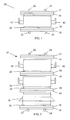
- the shell member 20 along with first flange 14 and second flange 16 is formed such that size of the reactor apparatus may be expanded by adding additional shell members 20.
- This embodiment is shown in Figure 2.
- additional shell members 20 may be added such that the second (bottom) flange 16 mates with the first (top) flange 14 of an adjacent shell member.
- two adjacent flanges are also separated by a gasket 28.
- each flange is at least about twice the width of the gaskets.
- Each of these shell members are substantially identical to each other, including the supports and fittings, and are the shell members are interchangeable.
- FIG. 2 illustrates an example of a reactor having three shell members 20 joined together to form a single reactor vessel
- the reactor apparatus 10 may include more or fewer than three shell members 20.
- the overall size of the reactor apparatus 10 is such that the interior cavity 38 contains a volume of about 10 ft 3 (0.283m 3 ) or more.
- each of the shell members with its integrally formed flanges preferably has a length of from about 7 feet (2.13m) to about 8 feet (2.44m) However, it should be understood that each shell member may be longer or shorter in length.
- a loose fluoropolymer liner 30 Lining all exposed interior surfaces of the reactor, including the inner surfaces of each of the top cover 12 and the bottom cover 18, is a loose fluoropolymer liner 30, shown in Figure 4.
- a "loose fluoropolymer liner” broadly refers to a liner which is fitted from a film or sheet of a fluoropolymer material and which covers the inner metallic surfaces of the reactor. Specifically, the liner 30 insulates all internal metal surfaces from corrosive reactants or reaction products present inside the reactor, but is not permanently molded to the reactor.
- a loose liner differs from a molded liner in that a loose liner is not sprayed-on or rotary-baked from liquid form, but is a pre-fabricated sheet material which is supported in the reactor.
- molded liners are coated onto the entire inside surface of a reactor vessel and are generally useful in small scale manufacturing applications.
- molded liners are very expensive to fabricate and are impractical for fitting large reactors.
- One main problem with molded liners is that they are known to break down structurally when placed under high pressures and when used over a long period of time.
- a loose liner is capable of withstanding very high pressures and very high temperatures, and is easily replaceable. Additionally, a loose liner is less porous than molded liners, has better overall strength and is not limited in thickness.
- the loose liner 30 is positioned into the reactor vessel using conventional application techniques, and is flared between two adjacent flanges 14 and 16 (or between top cover 12 and flange 14 and between flange 16 and bottom cover 18) such that the flanges fix the liner to the vessel.
- the flanges are at least about twice as wide as the gasket between the flanges. Flanges that are at least about twice as wide as the gasket width allow for self-regulating sealing pressure and reduces liner stress at the flange joints. This also avoids over-compressing the liner 30 between the flanges, yet maximizes the reliability of the gasket sealability. It is also within the preferred embodiment of the invention that the liner 30 is secured in place with secondary fasteners to hold the liner 30 in place during disassembly of the reactor apparatus 10.
- FIG. 6 further supporting the liner in the vessel are a plurality of secondary fasteners 46, preferably fastening screws that penetrate through the liner and are fixed to the flanges.
- the liner is initially fixed to the vessel at the flanges whereby a portion of the liner is flared onto a surface of one flange, wherein a second flange (or a cover) is then pressed onto the first flange, thus holding the liner between the two flanges.
- the dotted line shown in Figure 6 represents the boundary of the gasket 28, which preferably only extends from the edge of interior cavity 38 to the edge of bolt holes 44.
- the secondary fasteners 46 are then inserted through the liner and connected to at least one of the adjacent flanges to further support the liner against the flange.
- fasteners 46 function primarily to hold the liner in place during disassembly. This is an especially advantageous feature of the invention because it avoids complications associated with liner shrinking. More specifically, it has been found that upon disassembly of a reactor apparatus having a loose fluoropolymer liner that has experienced some extended use, the liner has exhibited some shrinkage in size. Accordingly, once the liner is released from its fixed position between adjacent flanges, the liner no longer fits and cannot be replaced upon reassembly of the reactor apparatus. Therefore, a new liner must be fitted to the vessel, which is very costly.
- the fluoropolymer liner preferably comprises a polymer selected from the group consisting of, but not limited to, fluorinated ethylene propylene, poly(vinylidene fluoride), polytetrafluoroethylene, perfluoroalkoxy polymer, ethylene tetrafluoroethylene, ethylene hexafluoropropylene, tetrafluoroethylene-hexafluoropropylene, polychlorotrifluoroethylene, ethylene chlorotrifluoroethylene and combinations thereof.
- polytrifluoroethylene and perfluoroalkoxy copolymer are the most preferred fluoropolymers.
- the liner sheet has a thickness of about 0.5 mm to about 15 mm, more preferably from about 3 mm to about 13 mm, and most preferably from about 5 to about 10 mm.
- a thickness of about 0.5 mm to about 15 mm, more preferably from about 3 mm to about 13 mm, and most preferably from about 5 to about 10 mm.
- such thicknesses may vary as determined by individual uses and applications of the reactor apparatus.
- the flanges are bolted together through bolt holes 44 using an circular array of bolt and washer combinations extending around and through the flanges. Sequential bolt torqueing around the flanges provides an evenly distributed bolting force on the flange sealing gaskets.
- the bolt seals are preferably continuously monitored by an on-stream ultrasonic bolt load monitoring system. Such monitoring provides instant and constant monitoring of the integrity of the flange seals, allowing for preventive measurements against the formation of leaks.
- torsion torque control may be used for practical tightening using inexpensive air-driven impact wrenches.
- a spring loaded washer is a compact spring in the shape of a washer that has been pressed into a dished shape and then hardened and tempered.
- One particularly preferred spring loaded washer for use in assembling the reactor apparatus is a Belleville washer.
- a Belleville washer is a disk spring that applies pressure to the connection once you clamp down on it with the proper amount of force. The advantage of this washer is that it applies clamping pressure along a continuous arc pattern, instead of concentrating it at one point. Additionally, such Belleville washers provide predictable bolting forces and maintains a positive sealing after the reactor has experienced numerous repeated cycles of pressure and temperature changes.
- the initial cold bolting force on the spring washers is preferably from about 2,000 to about 40,000 lbs (907 to 18100kg) force/bolt, more preferably from about 10,000 to about 33,000 lbs (4540 to 15000kg) force/bolt and most preferably from about 20,000 to about 23,000 lbs (9070kg to 10400kg) force/bolt.
- each shell member 20 includes at least one weep hole 34 extending through the shell and to the surface of the liner, and preferably a plurality of weep holes as seen in Fig. 4.
- These weep holes 34 are holes in the shell that allow reactants that permeate the fluoropolymer lining be vented out of the reactor. This prevents reactants from building up pressure between the liner and the shell wall and forming blisters in the liner.
- the weep holes are preferably from about 4.5 mm to about 10 mm in diameter, more preferably from about 5.5 mm to about 8.5 mm, most preferably from about 6.5 mm to about 8 mm.
- each shell member 20 includes at least eight weep holes.
- each shell member has four weep holes at each of its top and bottom ends, with each weep hole being separated from the next by 90° along the circumference of the shell member.
- Each of the inlets and outlets are preferably also provided with a weep hole.
- Each weep hole 34 is preferably equipped with a 3/8 inch to 1 1 ⁇ 2 inch (0.95 to 3.8 cm) NPT coupling.
- Each coupling is preferably comprised of the same metal used to form the shell member.
- the weep holes are equipped with fluoroplastic inserts 32 that extend to the inner surface of the shell and reinforce the unsupported liner spots at the weep holes 34.
- the fluoroplastic inserts 32 preferably comprise a fluoropolymer material selected from the group listed above.
- the reactor apparatus further include an active vacuum system that is connected to the weep hole system to prevent a vacuum collapse of the liner. This vacuum system prevents liner damage from vacuum collapsing in the event of improper operation of the reactor.
- the reactor is also capable of being heated or cooled well enough to keep the reaction temperature at a set, desired temperature, as well as at a desired pressure.
- the reactor apparatus is equipped with jackets 26.
- Jackets 26, as shown in Figures 1 and 2 preferably surround each shell member, and allow for controlled heating or cooling of the vessel. Jackets 26 are preferably spaced from the flanges to minimize excessive heating of the liner.
- the steam jacket is maintained at an operating temperature of from about 40°C to about and 375°C, more preferably from about 65°C to about 190°C and most preferably from about 100°C to about 155°C.
- the reactor is also preferably maintained at an operating pressure of from about 15 psig to about 350 psig, preferably from about 30 psig to about 250 psig and more preferably from about 75 psig to about 200 psig.
- jackets 26 are preferably supported by a support lug 36. While only a single support lug 36 is shown in Figure 2, it is preferred that each steam jacket 26 is supported by a separate support lug 36.
- the reactor apparatus of the invention may further include additional features that are conventionally used for supporting a reactor apparatus or for further securing joints.
- the reactor apparatus of the invention may include unit lifting and/or unit tailing trunions 42 at selected locations on the outer body of the reactor apparatus.
- the reactor apparatus may further include other conventional features that are not shown in the drawings.
- each of the covers and flanges preferably include lift lugs (at least two with pads on each section of the apparatus), ground lugs (at least two) and detector mounting clips that aid in the disassembly and/or moving of the apparatus.
- all carbon steel attachments to a nickel alloy must include an attachment pad having a minimum thickness of 1 ⁇ 4 inch (6.35 mm).
- the reactor apparatus may also include additional features not specifically mentioned herein as may be conventionally known by one skilled in the art, particularly features useful for disassembling and moving the reactor apparatus.
- a reactor apparatus is constructed as described above and having a 3,000 gallon interior volume (11,353 Liters).
- the reactor is pre-charged with antimony pentachloride catalyst.
- a chlorinated organic and hydrogen fluoride are then introduced into the reactor.
- the operating reactions of the reactor are set to 160 psig (11bar) and 220 °F (104.4 °C), and steam is introduced on the steam jacket to heat the reactor.
- the process yields at least 1,000 lb/hr (7.6 kg/min) of a hydrofluorocarbon, and accumulates at least 2000 hours of operating time without leaks or liner damage.
Landscapes
- Chemical & Material Sciences (AREA)
- Organic Chemistry (AREA)
- Chemical Kinetics & Catalysis (AREA)
- Physical Or Chemical Processes And Apparatus (AREA)
- Organic Low-Molecular-Weight Compounds And Preparation Thereof (AREA)
- Gasket Seals (AREA)
- Addition Polymer Or Copolymer, Post-Treatments, Or Chemical Modifications (AREA)
- Graft Or Block Polymers (AREA)
Applications Claiming Priority (2)
| Application Number | Priority Date | Filing Date | Title |
|---|---|---|---|
| US10/408,153 US7102040B2 (en) | 2003-04-04 | 2003-04-04 | Fluoropolymer lined metallic vessel design |
| PCT/US2004/010038 WO2004089535A1 (en) | 2003-04-04 | 2004-04-01 | Fluoropolymer lined reactor |
Publications (2)
| Publication Number | Publication Date |
|---|---|
| EP1628756A1 EP1628756A1 (en) | 2006-03-01 |
| EP1628756B1 true EP1628756B1 (en) | 2007-01-03 |
Family
ID=33097709
Family Applications (1)
| Application Number | Title | Priority Date | Filing Date |
|---|---|---|---|
| EP04749614A Expired - Lifetime EP1628756B1 (en) | 2003-04-04 | 2004-04-01 | Fluoropolymer lined reactor |
Country Status (10)
| Country | Link |
|---|---|
| US (2) | US7102040B2 (enExample) |
| EP (1) | EP1628756B1 (enExample) |
| JP (1) | JP4343947B2 (enExample) |
| CN (1) | CN100408158C (enExample) |
| AT (1) | ATE350147T1 (enExample) |
| DE (1) | DE602004004110T2 (enExample) |
| ES (1) | ES2277270T3 (enExample) |
| MX (1) | MXPA05010673A (enExample) |
| TW (1) | TW200518830A (enExample) |
| WO (1) | WO2004089535A1 (enExample) |
Families Citing this family (13)
| Publication number | Priority date | Publication date | Assignee | Title |
|---|---|---|---|---|
| JP4936970B2 (ja) * | 2007-04-20 | 2012-05-23 | 東レエンジニアリング株式会社 | マイクロ化学プラント |
| JP2010527867A (ja) * | 2007-05-29 | 2010-08-19 | シーディーアイ シールズ, インコーポレイテッド | 硬いフィットメントを有するブロー成型により一体成型された容器 |
| JP2009195773A (ja) * | 2008-02-19 | 2009-09-03 | Sumitomo Chemical Co Ltd | 化学装置 |
| WO2010144917A2 (en) * | 2009-06-12 | 2010-12-16 | Arysta Lifescience North America, Llc | A reusable tote for hazardous chemicals |
| MY145258A (en) * | 2009-07-06 | 2012-01-11 | Univ Sains Malaysia | A system for producing l-homophenylalanine and a process for producing l-homophenylalanine |
| ES2727023T3 (es) * | 2009-11-12 | 2019-10-11 | Framatome Inc | Reactores segmentados para cambios de capacidad y enriquecimiento en la conversión de hexafluoruro de uranio en dióxido de uranio |
| EP2516055B1 (en) * | 2009-12-22 | 2020-04-22 | ExxonMobil Chemical Patents Inc. | Separation vessels for use in polymerization processes and methods for cleaning same |
| US9233895B2 (en) | 2013-03-15 | 2016-01-12 | Honeywell International, Inc. | Process to manufacture 2-chloro-1,1,1,2-tetrafluoropropane (HCFC-244bb) |
| CN107827707A (zh) | 2013-03-15 | 2018-03-23 | 霍尼韦尔国际公司 | 制备2‑氯‑1,1,1,2‑四氟丙烷(HCFC‑244bb)的方法 |
| US20150225315A1 (en) * | 2014-02-10 | 2015-08-13 | Honeywell International Inc. | Reactor design for liquid phase fluorination |
| JP5826874B2 (ja) * | 2014-02-20 | 2015-12-02 | 株式会社セブン・セブン | コーヒー収納容器 |
| CN108482890A (zh) * | 2018-06-02 | 2018-09-04 | 南通安思卓新能源有限公司 | 一种可拼接的大型碳钢储碱罐 |
| CN109132246B (zh) * | 2018-08-30 | 2023-07-04 | 浙江科赛新材料科技有限公司 | 油罐接头 |
Family Cites Families (13)
| Publication number | Priority date | Publication date | Assignee | Title |
|---|---|---|---|---|
| US2913318A (en) * | 1955-02-08 | 1959-11-17 | Union Carbide Corp | Column-type reactor |
| US2970042A (en) * | 1956-03-01 | 1961-01-31 | Shell Oil Co | Vessel with replaceable pliable lining |
| US3135420A (en) * | 1962-06-22 | 1964-06-02 | Du Pont | Container for corrosive liquids |
| US3140006A (en) * | 1962-09-12 | 1964-07-07 | Shell Oil Co | Pressure vessel for containing hydrogen or mixtures thereof |
| US3490997A (en) * | 1965-01-07 | 1970-01-20 | Standard Oil Co | Dehydration of wet lower aliphatic monocarboxylic acid by distillation with alkali metal ions present |
| US3476009A (en) * | 1967-04-28 | 1969-11-04 | Teledyne Inc | Spring washer |
| FR2277004A1 (fr) | 1974-07-02 | 1976-01-30 | Carborundum Co | Reservoir a revetement interne en matiere elastomere ou plastique et procede de stabilisation de revetement |
| US5246549A (en) * | 1989-05-15 | 1993-09-21 | John Heil | Vacuum distillation system utilizing loose polymer lining |
| ES2123803T3 (es) * | 1993-07-29 | 1999-01-16 | Allied Signal Inc | Proceso para la preparacion de 1,1,1,3,3-pentafluoropropano. |
| ES2104521T3 (es) * | 1994-07-11 | 1999-05-01 | Allied Signal Inc | Proceso para la fabricacion de 1,1,1,3,3-pentafluoropropano. |
| US5763706A (en) * | 1996-07-03 | 1998-06-09 | Alliedsignal Inc. | Process for the manufacture of 1,1,1,3,3-pentafluoropropane and 1,1,1,3,3,3-hexafluoropropane |
| US5902912A (en) * | 1997-06-26 | 1999-05-11 | Alliedsignal Inc. | Process for preparing hydrofluorocarbons |
| US6939521B1 (en) * | 1997-11-21 | 2005-09-06 | Honeywell International Inc. | Fluoropolymer reactor with heat exchange jacket |
-
2003
- 2003-04-04 US US10/408,153 patent/US7102040B2/en not_active Expired - Lifetime
-
2004
- 2004-04-01 AT AT04749614T patent/ATE350147T1/de not_active IP Right Cessation
- 2004-04-01 MX MXPA05010673A patent/MXPA05010673A/es active IP Right Grant
- 2004-04-01 ES ES04749614T patent/ES2277270T3/es not_active Expired - Lifetime
- 2004-04-01 WO PCT/US2004/010038 patent/WO2004089535A1/en not_active Ceased
- 2004-04-01 JP JP2006509584A patent/JP4343947B2/ja not_active Expired - Lifetime
- 2004-04-01 EP EP04749614A patent/EP1628756B1/en not_active Expired - Lifetime
- 2004-04-01 CN CNB2004800149148A patent/CN100408158C/zh not_active Expired - Lifetime
- 2004-04-01 DE DE602004004110T patent/DE602004004110T2/de not_active Expired - Lifetime
- 2004-04-02 TW TW093109300A patent/TW200518830A/zh unknown
-
2005
- 2005-11-18 US US11/283,351 patent/US7780930B2/en not_active Expired - Lifetime
Also Published As
| Publication number | Publication date |
|---|---|
| JP4343947B2 (ja) | 2009-10-14 |
| MXPA05010673A (es) | 2005-12-12 |
| CN1798605A (zh) | 2006-07-05 |
| EP1628756A1 (en) | 2006-03-01 |
| ATE350147T1 (de) | 2007-01-15 |
| DE602004004110T2 (de) | 2007-07-12 |
| TW200518830A (en) | 2005-06-16 |
| US20040199031A1 (en) | 2004-10-07 |
| CN100408158C (zh) | 2008-08-06 |
| DE602004004110D1 (de) | 2007-02-15 |
| US20060079722A1 (en) | 2006-04-13 |
| US7102040B2 (en) | 2006-09-05 |
| US7780930B2 (en) | 2010-08-24 |
| ES2277270T3 (es) | 2007-07-01 |
| JP2006523140A (ja) | 2006-10-12 |
| WO2004089535A1 (en) | 2004-10-21 |
Similar Documents
| Publication | Publication Date | Title |
|---|---|---|
| EP1628756B1 (en) | Fluoropolymer lined reactor | |
| JP2006523140A5 (enExample) | ||
| US6939521B1 (en) | Fluoropolymer reactor with heat exchange jacket | |
| US11578022B2 (en) | Process for manufacture of 2-chloro-1,1,1-trifluoropropene | |
| EP0993425A1 (en) | Process for preparing hydrofluorocarbons | |
| CN104707540A (zh) | 板式反应器的制作方法 | |
| US11136282B2 (en) | Method for producing 2,3,3,3-tetrafluoropropene and facility for implementing said method | |
| EP2991757A1 (en) | Jacketed autoclave device for production of polyamides | |
| WO1999015268A1 (en) | Pipe reactor | |
| KR20160120320A (ko) | 액체상 불소화를 위한 반응기 설계 | |
| US20210261486A1 (en) | Method for producing 2-chloro-3,3,3-trifluoropropene and facility for implementing same | |
| US20210253501A1 (en) | Process for producing 2,3,3,3-tetrafluoropropene, and system for carrying out same | |
| JPH09501611A (ja) | 発熱及び吸熱反応方法 | |
| FR3098127A1 (fr) | Procédé de production de 2,3,3,3-tétrafluoropropène et réacteur pour la mise en œuvre de celui-ci | |
| CN107001233A (zh) | 用于光气化包含羟基、硫醇基、氨基和/或甲酰胺基团的化合物的方法 | |
| FR3082201A1 (fr) | Procede de production de 2,3,3,3-tetrafluoropropene, reacteur et installation pour la mise en oeuvre de celui-ci. | |
| EP3807239A1 (fr) | Procede production de 2,3,3,3-tetrafluoropropene et reacteur pour la mise en oeuvre de celui-ci | |
| MXPA99010401A (en) | Process for preparing hydrofluorocarbons |
Legal Events
| Date | Code | Title | Description |
|---|---|---|---|
| PUAI | Public reference made under article 153(3) epc to a published international application that has entered the european phase |
Free format text: ORIGINAL CODE: 0009012 |
|
| 17P | Request for examination filed |
Effective date: 20051102 |
|
| AK | Designated contracting states |
Kind code of ref document: A1 Designated state(s): AT BE BG CH CY CZ DE DK EE ES FI FR GB GR HU IE IT LI LU MC NL PL PT RO SE SI SK TR |
|
| R17P | Request for examination filed (corrected) |
Effective date: 20051102 |
|
| RBV | Designated contracting states (corrected) |
Designated state(s): AT BE BG CH CY CZ DE DK EE ES FI FR GB GR HU IE IT LI LU MC NL PL PT RO SE SI SK TR |
|
| GRAP | Despatch of communication of intention to grant a patent |
Free format text: ORIGINAL CODE: EPIDOSNIGR1 |
|
| DAX | Request for extension of the european patent (deleted) | ||
| GRAS | Grant fee paid |
Free format text: ORIGINAL CODE: EPIDOSNIGR3 |
|
| GRAA | (expected) grant |
Free format text: ORIGINAL CODE: 0009210 |
|
| AK | Designated contracting states |
Kind code of ref document: B1 Designated state(s): AT BE BG CH CY CZ DE DK EE ES FI FR GB GR HU IE IT LI LU MC NL PL PT RO SE SI SK TR |
|
| PG25 | Lapsed in a contracting state [announced via postgrant information from national office to epo] |
Ref country code: LI Free format text: LAPSE BECAUSE OF FAILURE TO SUBMIT A TRANSLATION OF THE DESCRIPTION OR TO PAY THE FEE WITHIN THE PRESCRIBED TIME-LIMIT Effective date: 20070103 Ref country code: CH Free format text: LAPSE BECAUSE OF FAILURE TO SUBMIT A TRANSLATION OF THE DESCRIPTION OR TO PAY THE FEE WITHIN THE PRESCRIBED TIME-LIMIT Effective date: 20070103 Ref country code: SI Free format text: LAPSE BECAUSE OF FAILURE TO SUBMIT A TRANSLATION OF THE DESCRIPTION OR TO PAY THE FEE WITHIN THE PRESCRIBED TIME-LIMIT Effective date: 20070103 Ref country code: PL Free format text: LAPSE BECAUSE OF FAILURE TO SUBMIT A TRANSLATION OF THE DESCRIPTION OR TO PAY THE FEE WITHIN THE PRESCRIBED TIME-LIMIT Effective date: 20070103 Ref country code: FI Free format text: LAPSE BECAUSE OF FAILURE TO SUBMIT A TRANSLATION OF THE DESCRIPTION OR TO PAY THE FEE WITHIN THE PRESCRIBED TIME-LIMIT Effective date: 20070103 Ref country code: AT Free format text: LAPSE BECAUSE OF FAILURE TO SUBMIT A TRANSLATION OF THE DESCRIPTION OR TO PAY THE FEE WITHIN THE PRESCRIBED TIME-LIMIT Effective date: 20070103 Ref country code: NL Free format text: LAPSE BECAUSE OF FAILURE TO SUBMIT A TRANSLATION OF THE DESCRIPTION OR TO PAY THE FEE WITHIN THE PRESCRIBED TIME-LIMIT Effective date: 20070103 Ref country code: DK Free format text: LAPSE BECAUSE OF FAILURE TO SUBMIT A TRANSLATION OF THE DESCRIPTION OR TO PAY THE FEE WITHIN THE PRESCRIBED TIME-LIMIT Effective date: 20070103 |
|
| REG | Reference to a national code |
Ref country code: GB Ref legal event code: FG4D |
|
| REF | Corresponds to: |
Ref document number: 602004004110 Country of ref document: DE Date of ref document: 20070215 Kind code of ref document: P |
|
| REG | Reference to a national code |
Ref country code: IE Ref legal event code: FG4D |
|
| PG25 | Lapsed in a contracting state [announced via postgrant information from national office to epo] |
Ref country code: SE Free format text: LAPSE BECAUSE OF FAILURE TO SUBMIT A TRANSLATION OF THE DESCRIPTION OR TO PAY THE FEE WITHIN THE PRESCRIBED TIME-LIMIT Effective date: 20070403 Ref country code: BG Free format text: LAPSE BECAUSE OF FAILURE TO SUBMIT A TRANSLATION OF THE DESCRIPTION OR TO PAY THE FEE WITHIN THE PRESCRIBED TIME-LIMIT Effective date: 20070403 |
|
| PG25 | Lapsed in a contracting state [announced via postgrant information from national office to epo] |
Ref country code: PT Free format text: LAPSE BECAUSE OF FAILURE TO SUBMIT A TRANSLATION OF THE DESCRIPTION OR TO PAY THE FEE WITHIN THE PRESCRIBED TIME-LIMIT Effective date: 20070604 |
|
| ET | Fr: translation filed | ||
| REG | Reference to a national code |
Ref country code: ES Ref legal event code: FG2A Ref document number: 2277270 Country of ref document: ES Kind code of ref document: T3 |
|
| NLV1 | Nl: lapsed or annulled due to failure to fulfill the requirements of art. 29p and 29m of the patents act | ||
| REG | Reference to a national code |
Ref country code: CH Ref legal event code: PL |
|
| PLBE | No opposition filed within time limit |
Free format text: ORIGINAL CODE: 0009261 |
|
| STAA | Information on the status of an ep patent application or granted ep patent |
Free format text: STATUS: NO OPPOSITION FILED WITHIN TIME LIMIT |
|
| PG25 | Lapsed in a contracting state [announced via postgrant information from national office to epo] |
Ref country code: SK Free format text: LAPSE BECAUSE OF FAILURE TO SUBMIT A TRANSLATION OF THE DESCRIPTION OR TO PAY THE FEE WITHIN THE PRESCRIBED TIME-LIMIT Effective date: 20070103 |
|
| 26N | No opposition filed |
Effective date: 20071005 |
|
| PG25 | Lapsed in a contracting state [announced via postgrant information from national office to epo] |
Ref country code: BE Free format text: LAPSE BECAUSE OF FAILURE TO SUBMIT A TRANSLATION OF THE DESCRIPTION OR TO PAY THE FEE WITHIN THE PRESCRIBED TIME-LIMIT Effective date: 20070103 Ref country code: RO Free format text: LAPSE BECAUSE OF FAILURE TO SUBMIT A TRANSLATION OF THE DESCRIPTION OR TO PAY THE FEE WITHIN THE PRESCRIBED TIME-LIMIT Effective date: 20070103 Ref country code: CZ Free format text: LAPSE BECAUSE OF FAILURE TO SUBMIT A TRANSLATION OF THE DESCRIPTION OR TO PAY THE FEE WITHIN THE PRESCRIBED TIME-LIMIT Effective date: 20070103 |
|
| PG25 | Lapsed in a contracting state [announced via postgrant information from national office to epo] |
Ref country code: GR Free format text: LAPSE BECAUSE OF FAILURE TO SUBMIT A TRANSLATION OF THE DESCRIPTION OR TO PAY THE FEE WITHIN THE PRESCRIBED TIME-LIMIT Effective date: 20070404 |
|
| PG25 | Lapsed in a contracting state [announced via postgrant information from national office to epo] |
Ref country code: IE Free format text: LAPSE BECAUSE OF NON-PAYMENT OF DUE FEES Effective date: 20070402 |
|
| PG25 | Lapsed in a contracting state [announced via postgrant information from national office to epo] |
Ref country code: EE Free format text: LAPSE BECAUSE OF FAILURE TO SUBMIT A TRANSLATION OF THE DESCRIPTION OR TO PAY THE FEE WITHIN THE PRESCRIBED TIME-LIMIT Effective date: 20070103 |
|
| PG25 | Lapsed in a contracting state [announced via postgrant information from national office to epo] |
Ref country code: MC Free format text: LAPSE BECAUSE OF NON-PAYMENT OF DUE FEES Effective date: 20070430 |
|
| PG25 | Lapsed in a contracting state [announced via postgrant information from national office to epo] |
Ref country code: CY Free format text: LAPSE BECAUSE OF FAILURE TO SUBMIT A TRANSLATION OF THE DESCRIPTION OR TO PAY THE FEE WITHIN THE PRESCRIBED TIME-LIMIT Effective date: 20070103 |
|
| PG25 | Lapsed in a contracting state [announced via postgrant information from national office to epo] |
Ref country code: LU Free format text: LAPSE BECAUSE OF NON-PAYMENT OF DUE FEES Effective date: 20070401 |
|
| PG25 | Lapsed in a contracting state [announced via postgrant information from national office to epo] |
Ref country code: HU Free format text: LAPSE BECAUSE OF FAILURE TO SUBMIT A TRANSLATION OF THE DESCRIPTION OR TO PAY THE FEE WITHIN THE PRESCRIBED TIME-LIMIT Effective date: 20070704 Ref country code: TR Free format text: LAPSE BECAUSE OF FAILURE TO SUBMIT A TRANSLATION OF THE DESCRIPTION OR TO PAY THE FEE WITHIN THE PRESCRIBED TIME-LIMIT Effective date: 20070103 |
|
| REG | Reference to a national code |
Ref country code: FR Ref legal event code: PLFP Year of fee payment: 13 |
|
| REG | Reference to a national code |
Ref country code: FR Ref legal event code: PLFP Year of fee payment: 14 |
|
| REG | Reference to a national code |
Ref country code: FR Ref legal event code: PLFP Year of fee payment: 15 |
|
| PGFP | Annual fee paid to national office [announced via postgrant information from national office to epo] |
Ref country code: ES Payment date: 20200511 Year of fee payment: 17 Ref country code: FR Payment date: 20200429 Year of fee payment: 17 |
|
| PGFP | Annual fee paid to national office [announced via postgrant information from national office to epo] |
Ref country code: IT Payment date: 20200424 Year of fee payment: 17 Ref country code: GB Payment date: 20200429 Year of fee payment: 17 |
|
| GBPC | Gb: european patent ceased through non-payment of renewal fee |
Effective date: 20210401 |
|
| PG25 | Lapsed in a contracting state [announced via postgrant information from national office to epo] |
Ref country code: GB Free format text: LAPSE BECAUSE OF NON-PAYMENT OF DUE FEES Effective date: 20210401 Ref country code: FR Free format text: LAPSE BECAUSE OF NON-PAYMENT OF DUE FEES Effective date: 20210430 |
|
| REG | Reference to a national code |
Ref country code: ES Ref legal event code: FD2A Effective date: 20220629 |
|
| PG25 | Lapsed in a contracting state [announced via postgrant information from national office to epo] |
Ref country code: ES Free format text: LAPSE BECAUSE OF NON-PAYMENT OF DUE FEES Effective date: 20210402 |
|
| PGFP | Annual fee paid to national office [announced via postgrant information from national office to epo] |
Ref country code: DE Payment date: 20220428 Year of fee payment: 19 |
|
| PG25 | Lapsed in a contracting state [announced via postgrant information from national office to epo] |
Ref country code: IT Free format text: LAPSE BECAUSE OF NON-PAYMENT OF DUE FEES Effective date: 20200401 |
|
| REG | Reference to a national code |
Ref country code: DE Ref legal event code: R119 Ref document number: 602004004110 Country of ref document: DE |
|
| PG25 | Lapsed in a contracting state [announced via postgrant information from national office to epo] |
Ref country code: DE Free format text: LAPSE BECAUSE OF NON-PAYMENT OF DUE FEES Effective date: 20231103 |
|
| PG25 | Lapsed in a contracting state [announced via postgrant information from national office to epo] |
Ref country code: IT Free format text: LAPSE BECAUSE OF NON-PAYMENT OF DUE FEES Effective date: 20210401 |