EP1628514A2 - Heat radiating structure for electronic equipment - Google Patents
Heat radiating structure for electronic equipment Download PDFInfo
- Publication number
- EP1628514A2 EP1628514A2 EP05016792A EP05016792A EP1628514A2 EP 1628514 A2 EP1628514 A2 EP 1628514A2 EP 05016792 A EP05016792 A EP 05016792A EP 05016792 A EP05016792 A EP 05016792A EP 1628514 A2 EP1628514 A2 EP 1628514A2
- Authority
- EP
- European Patent Office
- Prior art keywords
- heat
- duct
- casing
- heat sink
- electronic equipment
- Prior art date
- Legal status (The legal status is an assumption and is not a legal conclusion. Google has not performed a legal analysis and makes no representation as to the accuracy of the status listed.)
- Granted
Links
Images


Classifications
-
- H—ELECTRICITY
- H05—ELECTRIC TECHNIQUES NOT OTHERWISE PROVIDED FOR
- H05K—PRINTED CIRCUITS; CASINGS OR CONSTRUCTIONAL DETAILS OF ELECTRIC APPARATUS; MANUFACTURE OF ASSEMBLAGES OF ELECTRICAL COMPONENTS
- H05K7/00—Constructional details common to different types of electric apparatus
- H05K7/20—Modifications to facilitate cooling, ventilating, or heating
- H05K7/2089—Modifications to facilitate cooling, ventilating, or heating for power electronics, e.g. for inverters for controlling motor
- H05K7/20909—Forced ventilation, e.g. on heat dissipaters coupled to components
- H05K7/20918—Forced ventilation, e.g. on heat dissipaters coupled to components the components being isolated from air flow, e.g. hollow heat sinks, wind tunnels or funnels
-
- H—ELECTRICITY
- H02—GENERATION; CONVERSION OR DISTRIBUTION OF ELECTRIC POWER
- H02M—APPARATUS FOR CONVERSION BETWEEN AC AND AC, BETWEEN AC AND DC, OR BETWEEN DC AND DC, AND FOR USE WITH MAINS OR SIMILAR POWER SUPPLY SYSTEMS; CONVERSION OF DC OR AC INPUT POWER INTO SURGE OUTPUT POWER; CONTROL OR REGULATION THEREOF
- H02M7/00—Conversion of AC power input into DC power output; Conversion of DC power input into AC power output
- H02M7/003—Constructional details, e.g. physical layout, assembly, wiring or busbar connections
Definitions
- the invention relates to a heat radiating structure for electronic equipment, in which a heat generating part is housed inside of a casing.
- a temperature inside of the casing has become higher when heat generated at the heat generating part stays inside of the casing, thereby raising a problem such as degradation of performance or breakage of other electronic parts housed inside of the casing.
- the prior art has taken countermeasures such that an increase in temperature inside of the casing is prevented by radiating the heat generated at the heat generating part.
- electronic equipment such as a solar inverter of outdoor specifications, which is installed outdoors for use, includes many heat generating parts housed inside of a casing. Therefore, a heat radiating effect cannot be sufficiently produced only by fixing a heat sink to the heat generating part.
- a cooling fan has been disposed independently of the heat sink in the prior art, to allow outside air to flow inside of the casing, thereby further enhancing the heat radiating effect by the heat sink.
- the heat sink in the prior art has been constituted of a flat plate made of metal having a high heat conductivity such as aluminum and numerous fins projecting from one surface of the flat plate. Only both surfaces of the flat plate and both surfaces of each of the fins have served as heat radiating surfaces. The tip of each of the fins has not functioned as a heat radiating surface.
- the heat radiating area need be enlarged by increasing the size of the heat sink, thereby raising a problem that the electronic equipment cannot be reduced in size.
- a dustproof/waterproof structure has been required for the electronic equipment of the outdoor specifications, which is installed outdoors for use, in accordance with the standard of IP54, IP55 or the like.
- the electronic equipment for allowing the outside air to flow into the casing by the cooling fan disposed at a portion of the casing, so as to radiate the heat generated at the heat generating part, dust, rain water or the like may be sucked into the casing by the cooling fan, thereby raising a problem that the dustproof/waterproof structure is hardly adopted.
- an object of the invention is to provide a heat radiating structure for electronic equipment, in which a heat radiating effect is excellently produced, and further, a dustproof/waterproof structure can be readily adopted.
- a heat radiating structure for electronic equipment in a preferred embodiment according to the invention including a casing containing therein electronic parts and a printed board housed inside of an electronic part containing chamber defined inside of the casing, a heat generating part and the like, and a heat sink for radiating heat generated at the heat generating part, is characterized by including: a duct of an air-tight structure formed in such a manner as to surround the periphery of the electronic part containing chamber; a suction port formed at one end of the duct, for sucking outside air into the duct; an exhaust port formed at the other end of the duct, for exhausting air from the duct; a cooling fan disposed on the way of the duct; and a heat sink housed inside of the duct, the inside of the heat sink being divided into a plurality of passages by a heat radiating fin; wherein the heat generating part is fixed at an outside surface of the heat sink.
- the heat radiating structure for the electronic equipment in the above-described preferred embodiment according to the invention is constituted of the duct of the air-tight structure formed in such a manner as to surround the periphery of the electronic part containing chamber, so that dust, rain water or the like cannot be sucked into the electronic part containing chamber by the cooling fan, thereby providing an excellent dustproof/waterproof structure.
- the duct of the air-tight structure is formed between both side plates and upper plate of the casing and partition walls which are formed in such a manner as to surround the right, left and upper sides of the electronic part containing chamber, and further, the suction port is formed at a lower portion of one side plate of the casing while the exhaust port is formed at a lower portion of the other side plate of the casing.
- the partition walls can inhibit the dust, rain water or the like sucked into the duct from intruding into the electronic part containing chamber, thereby readily providing the electronic equipment of a dustproof/waterproof structure in accordance with a standard.
- the heat sink or the cooling fan is separated from and positioned above the suction port or the exhaust port, so that the heat sink or the cooling fan cannot be contaminated or broken or a heat radiating effect cannot be deteriorated caused by the dust or rain water intruding through the suction port or the exhaust port.
- the heat sink is formed into a shape of a polygonal cylinder, one side surface of the cylindrical portion of the heat sink being fixed onto a side of the casing while the heat generating part being fixed to the residual surfaces.
- all of the side surfaces except for the heat sink fixing surface serve as heat radiating surfaces, so that the heat can be radiated from a plurality of heat generating parts without any increase in size of the heat sink by fixing the heat generating parts to the heat radiating surfaces of the heat sink even in the case of the electronic equipment including the heat generating parts housed inside of a casing, thus reducing the size of the electronic equipment.
- Fig. 1 is a perspective view seen from above showing electronic equipment such as a solar inverter of outdoor specifications, which is installed outdoors for use;
- Fig. 2 is a perspective view seen from below;
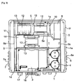
- Fig. 3 is a front view in a state in which a front cover is detached;
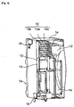
- Fig. 4 is a vertically perspective view taken along a line A-A of Fig. 1;
- Fig. 5 is a vertically perspective view taken along a line B-B of Fig. 1;
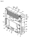
- Fig. 6 is a perspective view showing the vicinity of a heat sink; and
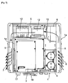
- Fig. 7 is a view explanatory of function.
- a main body 1 of electronic equipment is flat in a lengthwise direction, and includes a casing 1a made of metal formed into a substantially square shape, as viewed from the front.
- a front surface of the casing 1a is opened.
- a front cover 1c is fixed at four corners thereof to the casing 1a with fixtures 2 such as screws.
- An electronic part containing chamber 1d is defined inside of the casing 1a. Inside of the electronic part containing chamber 1d are contained one or a plurality of printed boards 3 mounting electronic parts thereon and other electronic parts 4.
- partition walls 5a and 5b are disposed in such a manner as to surround the upper, right and left sides of the electronic part containing chamber 1d in the casing 1a.
- a duct 5 of an air-tight structure is formed between the partition walls 5a and 5b and an upper plate 1e and right and left side plates 1f of the casing 1a.
- One end of the duct 5 communicates with suction ports 6 opened at a lower portion of one of the side plates 1f of the casing 1a, such that outside air can be introduced into the duct 5 through the suction ports 6.
- a flange 6a for inhibiting any intrusion of rain water or the like into the casing 1a projects at the suction port 6.
- the other end of the duct 5 communicates with exhaust ports 7 opened to a lower portion of the other side plate 1f of the casing 1a, such that air staying inside of the duct 5 can be exhausted to the outside.
- a flange 7a which is similar to the flange 6a for the suction port 6, projects at the exhaust port 7.
- a cooling fan 8 for sucking the outside air into the duct 5 through the suction ports 6 is disposed above the electronic part containing chamber 1d, that is, at an end on a side of the suction port at the duct 5 horizontally disposed at the upper portion inside of the casing 1a.
- the cooling fan 8 is constituted of a casing 8a, a fan 8b housed inside of the casing 8a and an electric motor 8c for driving the fan 8b.
- a heat sink 10 On an exhaust side of the cooling fan 8 is horizontally disposed a heat sink 10 of an integral structure formed by extruding metal having a high heat conductivity such as aluminum.
- the heat sink 10 includes a cylindrical portion 10a having a square cylindrical shape and heat radiating fins 10c for dividing the inside of the cylindrical portion 10a into a plurality of flat passages 10b as shown in Fig. 6.
- four outer surfaces of the cylindrical portion 10a and both side surfaces of each of the heat radiating fins 10c serve as heat radiating surfaces.
- the heat radiating surface is remarkably increased in area in comparison with a heat sink having a fin projecting at one surface of a flat plate in the prior art.
- Packings are interposed at a joint between an inlet side of the heat sink 10 and the casing 8a of the cooling fan 8 and at a joint between an outlet side of the heat sink 10 and the duct 5 on the exhaust port side, thereby preventing dust, rain water or the like, which has been sucked into the duct 5, from intruding onto the side of the electronic part containing chamber 1d through the joints.
- a heat generating part 12 such as an AC reactor or an insulated gate bipolar transistor (abbreviated as "an IGBT") is fixed at a front surface of the heat sink 10 via fixtures 13 such as screws.
- another heat generating part 12 such as a DC reactor is fixed to a heat radiating plate 14 tightly secured to a rear surface of the heat sink 10 via fixtures 13 such as screws.
- reference numeral 16 designates a drawing port for drawing a cable, not shown, into the casing 1a; 17, a connector for connecting a power source or the like; and 18, a bracket for fixing the main body 1 onto an outer wall or the like of a building.
- the main body 1 of the electronic equipment having the parts contained inside of the casing 1a is fixed onto the outer wall or the like of the building via the bracket 18, and then, is used.
- necessary wiring is carried out by drawing the cables into the casing 1a through the drawing ports 16 formed at the bottom surface of the casing 1a and the power source or the like is connected, thereby turning the electronic equipment into an operable state.
- the front cover 1c is attached to the front opening 1b of the casing 1a.
- the outside air sucked into the duct 5 is sent into the heat sink 10 having the square cylindrical shape disposed at the upper portion inside of the casing 1a by the cooling fan 8, as indicated by an arrow in Fig. 7.
- Heat which has been generated at the heat generating part 12 fixed to the front surface or the other heat generating part 12 fixed to the heat radiating plate 14 secured to the rear surface and has been transmitted to the heat sink 10, is efficiently radiated by the air passing through the heat sink 10.
- the heat staying inside of the electronic part containing chamber 1d is radiated to the air flowing through the heat sink 10 by a surface not having any heat generating part 12, which serves as a heat radiating surface, thereby radiating not only the heat generated at the heat generating part 12 but also the heat generated inside of the electronic part containing chamber 1d.
- the air passing through the heat sink 10 is exhausted from the exhaust ports 7 to the outside of the casing 1a through the duct 5 on the side of the exhaust ports 7.
- the heat generated at the heat generating part 12 is radiated by sequentially repeating the above-described operation. Since the suction ports 6 for sucking the outside air are formed at the lower portion at either side surface of the casing 1a and the heat sink is disposed inside of the duct 5 at the upper portion of the casing 1a, the dust, rain water or the like sucked through the suction ports 6 together with the outside air seldom reaches the heat sink 10.
- the duct 5 has the air-tight structure, so that the dust, rain water or the like intruding into the duct 5 is prevented from intruding into the electronic part containing chamber 1d containing the electronic part 4 or the printed board 3 therein. Consequently, it is possible to readily provide electronic equipment of a dustproof/waterproof structure in accordance with the standard of IP54 or IP55.
- the heat generated at the heat generating parts 12 can be radiated by fixing the heat generating parts 12 to the residual three sides.
- heat generated at a plurality of heat generating parts 12 can be radiated without any increase in size of the heat sink 10.
- the heat sink 10 never obstructs the reduction of the size of the electronic equipment.
- the invention may be applied to floor-standing electronic equipment, which is installed on a floor for use, or electronic equipment installed indoors for use.
- the heat sink 10 has been formed into the square cylindrical shape, it may be formed into a polygonal shape such as a pentagon or a hexagon. Alternatively, the cooling fan 8 may be disposed downstream of the heat sink 10.
- the heat radiating structure for the electronic equipment according to the invention With the heat radiating structure for the electronic equipment according to the invention, almost all of the outside air sucked into the duct by the cooling fan flows through the heat sink, to thus radiate the heat generated at the heat generating part fixed to the heat sink, thereby efficiently radiating the heat generated at the heat generating part. Furthermore, since no dust, rain water or the like sucked into the duct can intrude into the electronic part containing chamber, the heat radiating structure for the electronic equipment according to the invention is optimum for the heat radiating structure for the electronic equipment having the heat generating parts disposed inside of the casing.
Landscapes
- Engineering & Computer Science (AREA)
- Microelectronics & Electronic Packaging (AREA)
- Power Engineering (AREA)
- Physics & Mathematics (AREA)
- Thermal Sciences (AREA)
- Cooling Or The Like Of Electrical Apparatus (AREA)
Abstract
Description
- The invention relates to a heat radiating structure for electronic equipment, in which a heat generating part is housed inside of a casing.
- In, for example, electronic equipment including a heat generating part such as a power source device housed inside of a casing in the prior art, a temperature inside of the casing has become higher when heat generated at the heat generating part stays inside of the casing, thereby raising a problem such as degradation of performance or breakage of other electronic parts housed inside of the casing.
- In view of this, the prior art has taken countermeasures such that an increase in temperature inside of the casing is prevented by radiating the heat generated at the heat generating part.
- Alternatively, there has been conventionally known a method for effectively radiating heat generated at a heat generating part, in which a heat sink having numerous fins is fixed to the heat generating part, to thus enlarge a heat radiating area, thereby enhancing a heat radiating effect at the heat generating part, as disclosed in, for example, Japanese Patent Application Laid-open (JP-A) No. 11-233980.
- Otherwise, electronic equipment such as a solar inverter of outdoor specifications, which is installed outdoors for use, includes many heat generating parts housed inside of a casing. Therefore, a heat radiating effect cannot be sufficiently produced only by fixing a heat sink to the heat generating part.
- In view of this, a cooling fan has been disposed independently of the heat sink in the prior art, to allow outside air to flow inside of the casing, thereby further enhancing the heat radiating effect by the heat sink.
- However, the heat sink in the prior art has been constituted of a flat plate made of metal having a high heat conductivity such as aluminum and numerous fins projecting from one surface of the flat plate. Only both surfaces of the flat plate and both surfaces of each of the fins have served as heat radiating surfaces. The tip of each of the fins has not functioned as a heat radiating surface.
- As a consequence, in the case where the heat sink is used for radiating the heat in the electronic equipment such as the solar inverter using the many heat generating parts, the heat radiating area need be enlarged by increasing the size of the heat sink, thereby raising a problem that the electronic equipment cannot be reduced in size.
- In addition, a dustproof/waterproof structure has been required for the electronic equipment of the outdoor specifications, which is installed outdoors for use, in accordance with the standard of IP54, IP55 or the like. However, in the case of the electronic equipment for allowing the outside air to flow into the casing by the cooling fan disposed at a portion of the casing, so as to radiate the heat generated at the heat generating part, dust, rain water or the like may be sucked into the casing by the cooling fan, thereby raising a problem that the dustproof/waterproof structure is hardly adopted.
- The invention has been accomplished to solve the above-described problems experienced in the prior art. Therefore, an object of the invention is to provide a heat radiating structure for electronic equipment, in which a heat radiating effect is excellently produced, and further, a dustproof/waterproof structure can be readily adopted.
- A heat radiating structure for electronic equipment in a preferred embodiment according to the invention including a casing containing therein electronic parts and a printed board housed inside of an electronic part containing chamber defined inside of the casing, a heat generating part and the like, and a heat sink for radiating heat generated at the heat generating part, is
characterized by including: a duct of an air-tight structure formed in such a manner as to surround the periphery of the electronic part containing chamber; a suction port formed at one end of the duct, for sucking outside air into the duct; an exhaust port formed at the other end of the duct, for exhausting air from the duct; a cooling fan disposed on the way of the duct; and a heat sink housed inside of the duct, the inside of the heat sink being divided into a plurality of passages by a heat radiating fin; wherein the heat generating part is fixed at an outside surface of the heat sink. - With the above-described configuration, almost all of the outside air sucked into the duct by the cooling fan flows inside of the heat sink, to thus radiate the heat generated at the heat generating part fixed to the heat sink, thereby efficiently radiating the heat generated at the heat generating part. Furthermore, the inside of the electronic part containing chamber cannot become high in temperature caused by the heat generated at the heat generating part, thus preventing any degradation of the performance or breakage of the electronic part contained inside of the electronic part containing chamber due to the heat in advance.
- Additionally, the heat radiating structure for the electronic equipment in the above-described preferred embodiment according to the invention is constituted of the duct of the air-tight structure formed in such a manner as to surround the periphery of the electronic part containing chamber, so that dust, rain water or the like cannot be sucked into the electronic part containing chamber by the cooling fan, thereby providing an excellent dustproof/waterproof structure.
- In a heat radiating structure for electronic equipment in another preferred embodiment according to the invention, the duct of the air-tight structure is formed between both side plates and upper plate of the casing and partition walls which are formed in such a manner as to surround the right, left and upper sides of the electronic part containing chamber, and further, the suction port is formed at a lower portion of one side plate of the casing while the exhaust port is formed at a lower portion of the other side plate of the casing.
- With the above-described configuration, the partition walls can inhibit the dust, rain water or the like sucked into the duct from intruding into the electronic part containing chamber, thereby readily providing the electronic equipment of a dustproof/waterproof structure in accordance with a standard. Furthermore, the heat sink or the cooling fan is separated from and positioned above the suction port or the exhaust port, so that the heat sink or the cooling fan cannot be contaminated or broken or a heat radiating effect cannot be deteriorated caused by the dust or rain water intruding through the suction port or the exhaust port.
- In a heat radiating structure for electronic equipment in a further preferred embodiment according to the invention, the heat sink is formed into a shape of a polygonal cylinder, one side surface of the cylindrical portion of the heat sink being fixed onto a side of the casing while the heat generating part being fixed to the residual surfaces.
- With the above-described configuration, all of the side surfaces except for the heat sink fixing surface serve as heat radiating surfaces, so that the heat can be radiated from a plurality of heat generating parts without any increase in size of the heat sink by fixing the heat generating parts to the heat radiating surfaces of the heat sink even in the case of the electronic equipment including the heat generating parts housed inside of a casing, thus reducing the size of the electronic equipment.
- With the heat radiating structure for the electronic equipment according to the invention, almost all of the outside air sucked into the duct by the cooling fan flows through the heat sink, to thus radiate the heat generated at the heat generating part fixed to the heat sink, thereby efficiently radiating the heat generated at the heat generating part. Furthermore, no dust, rain water or the like sucked into the duct can intrude into the electronic part containing chamber, thereby readily providing the electronic equipment of the dustproof/waterproof structure in accordance with the standard.
-
- Fig. 1 shows a perspective view seen from above showing electronic equipment adopting a heat radiating structure in a preferred embodiment according to the invention.
- Fig. 2 shows a perspective view seen from below showing the electronic equipment adopting the heat radiating structure in the preferred embodiment according to the invention.
- Fig. 3 shows a front view showing the electronic equipment adopting the heat radiating structure in a state in which a front cover is detached in the preferred embodiment according to the invention.
- Fig. 4 shows a cross-sectional view taken along a line A-A of Fig. 1.
- Fig. 5 shows a cross-sectional view taken along a line B-B of Fig. 1.
- Fig. 6 shows an enlarged perspective view showing the vicinity of a heat sink in the heat radiating structure for the electronic equipment in the preferred embodiment according to the invention, and
- Fig. 7 shows a view explanatory of function of the heat radiating structure for the electronic equipment in the preferred embodiment according to the invention.
- A description will be given below of a preferred embodiment according to the invention in reference to the attached drawings.
- Fig. 1 is a perspective view seen from above showing electronic equipment such as a solar inverter of outdoor specifications, which is installed outdoors for use; Fig. 2 is a perspective view seen from below; Fig. 3 is a front view in a state in which a front cover is detached; Fig. 4 is a vertically perspective view taken along a line A-A of Fig. 1; Fig. 5 is a vertically perspective view taken along a line B-B of Fig. 1; Fig. 6 is a perspective view showing the vicinity of a heat sink; and Fig. 7 is a view explanatory of function.
- A
main body 1 of electronic equipment is flat in a lengthwise direction, and includes acasing 1a made of metal formed into a substantially square shape, as viewed from the front. - A front surface of the
casing 1a is opened. To an opening 1b is detachably attached afront cover 1c. Thefront cover 1c is fixed at four corners thereof to thecasing 1a withfixtures 2 such as screws. - An electronic
part containing chamber 1d is defined inside of thecasing 1a. Inside of the electronicpart containing chamber 1d are contained one or a plurality of printedboards 3 mounting electronic parts thereon and otherelectronic parts 4. - Additionally,
partition walls part containing chamber 1d in thecasing 1a. Aduct 5 of an air-tight structure is formed between thepartition walls upper plate 1e and right andleft side plates 1f of thecasing 1a. - One end of the
duct 5 communicates withsuction ports 6 opened at a lower portion of one of theside plates 1f of thecasing 1a, such that outside air can be introduced into theduct 5 through thesuction ports 6. Aflange 6a for inhibiting any intrusion of rain water or the like into thecasing 1a projects at thesuction port 6. In contrast, the other end of theduct 5 communicates withexhaust ports 7 opened to a lower portion of theother side plate 1f of thecasing 1a, such that air staying inside of theduct 5 can be exhausted to the outside. Aflange 7a, which is similar to theflange 6a for thesuction port 6, projects at theexhaust port 7. - A
cooling fan 8 for sucking the outside air into theduct 5 through thesuction ports 6 is disposed above the electronicpart containing chamber 1d, that is, at an end on a side of the suction port at theduct 5 horizontally disposed at the upper portion inside of thecasing 1a. - The
cooling fan 8 is constituted of acasing 8a, afan 8b housed inside of thecasing 8a and anelectric motor 8c for driving thefan 8b. On an exhaust side of thecooling fan 8 is horizontally disposed aheat sink 10 of an integral structure formed by extruding metal having a high heat conductivity such as aluminum. - The
heat sink 10 includes acylindrical portion 10a having a square cylindrical shape andheat radiating fins 10c for dividing the inside of thecylindrical portion 10a into a plurality offlat passages 10b as shown in Fig. 6. In this manner, four outer surfaces of thecylindrical portion 10a and both side surfaces of each of theheat radiating fins 10c serve as heat radiating surfaces. As a consequence, the heat radiating surface is remarkably increased in area in comparison with a heat sink having a fin projecting at one surface of a flat plate in the prior art. - Packings, not shown, are interposed at a joint between an inlet side of the
heat sink 10 and thecasing 8a of thecooling fan 8 and at a joint between an outlet side of theheat sink 10 and theduct 5 on the exhaust port side, thereby preventing dust, rain water or the like, which has been sucked into theduct 5, from intruding onto the side of the electronicpart containing chamber 1d through the joints. - A
heat generating part 12 such as an AC reactor or an insulated gate bipolar transistor (abbreviated as "an IGBT") is fixed at a front surface of theheat sink 10 viafixtures 13 such as screws. In addition, anotherheat generating part 12 such as a DC reactor is fixed to aheat radiating plate 14 tightly secured to a rear surface of theheat sink 10 viafixtures 13 such as screws. - Incidentally, in the drawings,
reference numeral 16 designates a drawing port for drawing a cable, not shown, into thecasing 1a; 17, a connector for connecting a power source or the like; and 18, a bracket for fixing themain body 1 onto an outer wall or the like of a building. - Next, explanation will be made on the function of the heat radiating structure for the electronic equipment such constituted as described above.
- The
main body 1 of the electronic equipment having the parts contained inside of thecasing 1a is fixed onto the outer wall or the like of the building via thebracket 18, and then, is used. In using themain body 1, necessary wiring is carried out by drawing the cables into thecasing 1a through the drawingports 16 formed at the bottom surface of thecasing 1a and the power source or the like is connected, thereby turning the electronic equipment into an operable state. Thereafter, thefront cover 1c is attached to thefront opening 1b of thecasing 1a. - In this state, when the electronic equipment is started to be operated, the cooling
fan 8 is rotated, and then, the outside air is sucked into theduct 5 through thesuction ports 6. - The outside air sucked into the
duct 5 is sent into theheat sink 10 having the square cylindrical shape disposed at the upper portion inside of thecasing 1a by the coolingfan 8, as indicated by an arrow in Fig. 7. - Heat, which has been generated at the
heat generating part 12 fixed to the front surface or the otherheat generating part 12 fixed to theheat radiating plate 14 secured to the rear surface and has been transmitted to theheat sink 10, is efficiently radiated by the air passing through theheat sink 10. - The heat staying inside of the electronic
part containing chamber 1d is radiated to the air flowing through theheat sink 10 by a surface not having anyheat generating part 12, which serves as a heat radiating surface, thereby radiating not only the heat generated at theheat generating part 12 but also the heat generated inside of the electronicpart containing chamber 1d. - The air passing through the
heat sink 10 is exhausted from theexhaust ports 7 to the outside of thecasing 1a through theduct 5 on the side of theexhaust ports 7. Hereinafter, the heat generated at theheat generating part 12 is radiated by sequentially repeating the above-described operation. Since thesuction ports 6 for sucking the outside air are formed at the lower portion at either side surface of thecasing 1a and the heat sink is disposed inside of theduct 5 at the upper portion of thecasing 1a, the dust, rain water or the like sucked through thesuction ports 6 together with the outside air seldom reaches theheat sink 10. In addition, theduct 5 has the air-tight structure, so that the dust, rain water or the like intruding into theduct 5 is prevented from intruding into the electronicpart containing chamber 1d containing theelectronic part 4 or the printedboard 3 therein. Consequently, it is possible to readily provide electronic equipment of a dustproof/waterproof structure in accordance with the standard of IP54 or IP55. - Even in the case where one outer surface of the
heat sink 10 formed into the square cylindrical shape is fixed to thecasing 1a, the heat generated at theheat generating parts 12 can be radiated by fixing theheat generating parts 12 to the residual three sides. As a consequence, even in electronic equipment such as a solar inverter having manyheat generating parts 12 housed inside acasing 1a, heat generated at a plurality ofheat generating parts 12 can be radiated without any increase in size of theheat sink 10. Thus, theheat sink 10 never obstructs the reduction of the size of the electronic equipment. - Incidentally, although the description has been given of the wall-mounted electronic equipment, in which the
main body 1 of the electronic equipment is fixed onto the wall surface of the building for use, in the above-described preferred embodiment, the invention may be applied to floor-standing electronic equipment, which is installed on a floor for use, or electronic equipment installed indoors for use. - Otherwise, although the
heat sink 10 has been formed into the square cylindrical shape, it may be formed into a polygonal shape such as a pentagon or a hexagon. Alternatively, the coolingfan 8 may be disposed downstream of theheat sink 10. - With the heat radiating structure for the electronic equipment according to the invention, almost all of the outside air sucked into the duct by the cooling fan flows through the heat sink, to thus radiate the heat generated at the heat generating part fixed to the heat sink, thereby efficiently radiating the heat generated at the heat generating part. Furthermore, since no dust, rain water or the like sucked into the duct can intrude into the electronic part containing chamber, the heat radiating structure for the electronic equipment according to the invention is optimum for the heat radiating structure for the electronic equipment having the heat generating parts disposed inside of the casing.
Claims (3)
- A heat radiating structure for electronic equipment including a casing (1a) containing therein electronic parts (4) and a printed board (3) housed inside of an electronic part containing chamber (1d) defined inside of the casing (1a), a heat generating part (12) and the like, and a heat sink (10) for radiating heat generated at the heat generating part (12), the heat radiating structure is characterized by including:a duct (5) of an air-tight structure formed in such a manner as to surround the periphery of the electronic part containing chamber (1d);a suction port (6) formed at one end of the duct (5), for sucking outside air into the duct (5);an exhaust port (7) formed at the other end of the duct (5), for exhausting air from the duct (5);a cooling fan (8) disposed on the way of the duct (5) ; anda heat sink (10) housed inside of the duct (5), the inside of the heat sink (10) being divided into a plurality of passages (10b) by a heat radiating fin (10c);wherein the heat generating part (12) is fixed at an outer surface of the heat sink (10).
- A heat radiating structure for electronic equipment according to claim 1, characterized in that the duct (5) of the air-tight structure is formed between both side plates and upper plate of the casing (1a) and partition walls which are formed in such a manner as to surround the right, left and upper sides of the electronic part containing chamber (1d), and further, the suction port (6) is formed at a lower portion of one side plate of the casing (1a) while the exhaust port (7) is formed at a lower portion of the other side plate of the casing (1a).
- A heat radiating structure for electronic equipment according to claim 1 or claim 2, characterized in that the heat sink (10) is formed into a shape of a polygonal cylinder, one side surface of the cylindrical portion (10a) of the heat sink (10) being fixed onto a side of the casing (1a) while the heat generating part (12) being fixed to the residual surfaces.
Applications Claiming Priority (1)
| Application Number | Priority Date | Filing Date | Title |
|---|---|---|---|
| JP2004232651A JP4265505B2 (en) | 2004-08-09 | 2004-08-09 | Heat dissipation structure of electronic equipment |
Publications (3)
| Publication Number | Publication Date |
|---|---|
| EP1628514A2 true EP1628514A2 (en) | 2006-02-22 |
| EP1628514A3 EP1628514A3 (en) | 2008-07-23 |
| EP1628514B1 EP1628514B1 (en) | 2011-05-11 |
Family
ID=35427995
Family Applications (1)
| Application Number | Title | Priority Date | Filing Date |
|---|---|---|---|
| EP20050016792 Expired - Lifetime EP1628514B1 (en) | 2004-08-09 | 2005-08-02 | Heat radiating structure for electronic equipment |
Country Status (5)
| Country | Link |
|---|---|
| EP (1) | EP1628514B1 (en) |
| JP (1) | JP4265505B2 (en) |
| CN (1) | CN1735330B (en) |
| ES (1) | ES2361631T3 (en) |
| TW (1) | TWI264991B (en) |
Cited By (10)
| Publication number | Priority date | Publication date | Assignee | Title |
|---|---|---|---|---|
| EP1971196A3 (en) * | 2007-01-22 | 2008-09-24 | Themis Computer | Clamshell enclosure for electronic circuit assemblies |
| WO2008129134A1 (en) * | 2007-04-23 | 2008-10-30 | Epec Oy | Method and arrangement for cooling equipment box |
| ITMI20091254A1 (en) * | 2009-07-14 | 2011-01-15 | Infor System S R L | SYSTEM FOR THE INSTALLATION OF PHOTOVOLTAIC MODULES IN ELECTRICAL SAFETY CONDITIONS AND RELATED INSTALLATION METHOD. |
| EP2424054A4 (en) * | 2009-04-20 | 2014-04-02 | Mitsubishi Electric Corp | HOUSING UNIT OF AN ELECTRONIC APPARATUS |
| EP2879476A1 (en) * | 2013-11-29 | 2015-06-03 | ABB Oy | Electric apparatus |
| GB2503407B (en) * | 2011-10-10 | 2015-12-09 | Control Tech Ltd | Barrier device |
| EP2385753A3 (en) * | 2010-05-05 | 2018-02-28 | Custom Sensors & Technologies, Inc. | Solid state switching device with integral heatsink |
| EP3683534A1 (en) * | 2019-01-17 | 2020-07-22 | LSIS Co., Ltd. | Heatsink module for inverter |
| CN112449559A (en) * | 2020-11-27 | 2021-03-05 | 佛山市青松科技股份有限公司 | Outdoor LED display screen radiator |
| CN112911851A (en) * | 2020-12-28 | 2021-06-04 | 青岛鼎信通讯股份有限公司 | Outdoor case of distributed active unbalance compensation device with good ventilation |
Families Citing this family (19)
| Publication number | Priority date | Publication date | Assignee | Title |
|---|---|---|---|---|
| JP4798287B2 (en) * | 2008-02-06 | 2011-10-19 | パナソニック株式会社 | Electrical equipment |
| EP2355639B1 (en) * | 2008-12-02 | 2014-07-02 | Hitachi, Ltd. | Operation processor |
| JP4693925B2 (en) | 2009-09-30 | 2011-06-01 | 株式会社東芝 | Electronics |
| JP5706149B2 (en) | 2010-02-26 | 2015-04-22 | パナソニックIpマネジメント株式会社 | Electrical equipment |
| JP2011188671A (en) * | 2010-03-10 | 2011-09-22 | Daihen Corp | Power supply apparatus |
| JP2011192809A (en) | 2010-03-15 | 2011-09-29 | Omron Corp | Power conditioner device and module substrate structure using the same |
| JP5747633B2 (en) * | 2010-08-02 | 2015-07-15 | 富士電機株式会社 | Electronics |
| JP5496018B2 (en) * | 2010-08-20 | 2014-05-21 | 株式会社日立国際電気 | Cooling device for multi-stage electronic equipment |
| JP5127902B2 (en) * | 2010-09-21 | 2013-01-23 | レノボ・シンガポール・プライベート・リミテッド | Electronic device heat dissipation device and electronic device |
| BR112013026340B1 (en) | 2011-04-18 | 2021-03-23 | Sony Computer Entertainment, Inc | ELECTRONIC DEVICE |
| JP5684047B2 (en) * | 2011-05-23 | 2015-03-11 | 株式会社三社電機製作所 | Electrical equipment |
| JP5515129B1 (en) * | 2013-05-23 | 2014-06-11 | 山佐株式会社 | Board case for gaming machine and gaming machine |
| CN104765432A (en) * | 2014-01-02 | 2015-07-08 | 鸿富锦精密电子(天津)有限公司 | Server combination |
| JP6116519B2 (en) * | 2014-05-02 | 2017-04-19 | 三菱電機株式会社 | Amplifier |
| JP6595781B2 (en) * | 2015-03-19 | 2019-10-23 | 株式会社エンビジョンAescジャパン | Portable power supply |
| JP2018160552A (en) * | 2017-03-23 | 2018-10-11 | 新電元工業株式会社 | Heat dissipation structure |
| JP6269882B1 (en) * | 2017-03-31 | 2018-01-31 | 富士電機株式会社 | Outdoor board |
| CN110636737A (en) * | 2018-06-25 | 2019-12-31 | 中兴通讯股份有限公司 | Cooling device for communication equipment |
| US12261448B2 (en) | 2022-06-07 | 2025-03-25 | Honeywell International Inc. | Low power sensor with energy harvesting |
Family Cites Families (5)
| Publication number | Priority date | Publication date | Assignee | Title |
|---|---|---|---|---|
| US4520425A (en) * | 1982-08-12 | 1985-05-28 | Mitsubishi Denki Kabushiki Kaisha | Control apparatus with improved structure for cooling circuit elements |
| KR920005988B1 (en) * | 1988-08-31 | 1992-07-25 | 가부시기가이샤 히다찌세이사꾸쇼 | Inverter |
| DE4015030C1 (en) * | 1990-05-10 | 1991-11-21 | Bicc-Vero Elektronics Gmbh, 2800 Bremen, De | |
| TW265430B (en) * | 1994-06-30 | 1995-12-11 | Intel Corp | Ducted opposing bonded fin heat sink blower multi-microprocessor cooling system |
| DE20016013U1 (en) * | 2000-09-15 | 2001-11-08 | Siemens AG, 80333 München | Control cabinet with improved heat dissipation |
-
2004
- 2004-08-09 JP JP2004232651A patent/JP4265505B2/en not_active Expired - Fee Related
-
2005
- 2005-08-02 EP EP20050016792 patent/EP1628514B1/en not_active Expired - Lifetime
- 2005-08-02 ES ES05016792T patent/ES2361631T3/en not_active Expired - Lifetime
- 2005-08-08 TW TW94126653A patent/TWI264991B/en not_active IP Right Cessation
- 2005-08-09 CN CN 200510089763 patent/CN1735330B/en not_active Expired - Fee Related
Cited By (13)
| Publication number | Priority date | Publication date | Assignee | Title |
|---|---|---|---|---|
| EP1971196A3 (en) * | 2007-01-22 | 2008-09-24 | Themis Computer | Clamshell enclosure for electronic circuit assemblies |
| EP2143313A4 (en) * | 2007-04-23 | 2016-11-16 | Ponsse Oyj | Method and arrangement for cooling equipment box |
| WO2008129134A1 (en) * | 2007-04-23 | 2008-10-30 | Epec Oy | Method and arrangement for cooling equipment box |
| EP2424054A4 (en) * | 2009-04-20 | 2014-04-02 | Mitsubishi Electric Corp | HOUSING UNIT OF AN ELECTRONIC APPARATUS |
| ITMI20091254A1 (en) * | 2009-07-14 | 2011-01-15 | Infor System S R L | SYSTEM FOR THE INSTALLATION OF PHOTOVOLTAIC MODULES IN ELECTRICAL SAFETY CONDITIONS AND RELATED INSTALLATION METHOD. |
| EP2385753A3 (en) * | 2010-05-05 | 2018-02-28 | Custom Sensors & Technologies, Inc. | Solid state switching device with integral heatsink |
| GB2503407B (en) * | 2011-10-10 | 2015-12-09 | Control Tech Ltd | Barrier device |
| US9433123B2 (en) | 2013-11-29 | 2016-08-30 | Abb Technology Oy | Electric apparatus |
| EP2879476A1 (en) * | 2013-11-29 | 2015-06-03 | ABB Oy | Electric apparatus |
| EP3683534A1 (en) * | 2019-01-17 | 2020-07-22 | LSIS Co., Ltd. | Heatsink module for inverter |
| US11234348B2 (en) | 2019-01-17 | 2022-01-25 | Lsis Co., Ltd. | Heatsink module for inverter |
| CN112449559A (en) * | 2020-11-27 | 2021-03-05 | 佛山市青松科技股份有限公司 | Outdoor LED display screen radiator |
| CN112911851A (en) * | 2020-12-28 | 2021-06-04 | 青岛鼎信通讯股份有限公司 | Outdoor case of distributed active unbalance compensation device with good ventilation |
Also Published As
| Publication number | Publication date |
|---|---|
| TWI264991B (en) | 2006-10-21 |
| JP4265505B2 (en) | 2009-05-20 |
| JP2006054215A (en) | 2006-02-23 |
| ES2361631T3 (en) | 2011-06-20 |
| EP1628514B1 (en) | 2011-05-11 |
| TW200614907A (en) | 2006-05-01 |
| CN1735330B (en) | 2010-12-29 |
| CN1735330A (en) | 2006-02-15 |
| EP1628514A3 (en) | 2008-07-23 |
Similar Documents
| Publication | Publication Date | Title |
|---|---|---|
| EP1628514B1 (en) | Heat radiating structure for electronic equipment | |
| CN110235536B (en) | Cooling device and robot control device having such a cooling device | |
| JP3303588B2 (en) | control panel | |
| JP6433631B2 (en) | Power converter | |
| CN104584408A (en) | Power conversion apparatus | |
| CN1726632A (en) | Frequency converter with air cooling | |
| JP2000232288A (en) | Power converter | |
| CN214480301U (en) | Drive and control integrated machine and control cabinet | |
| JP4042520B2 (en) | Communication equipment mounting structure and heat dissipation method | |
| JP7019069B2 (en) | Outdoor unit of control board and air conditioner | |
| JP2015029147A (en) | Electronic component cooling structure | |
| CN217849909U (en) | Heat radiation structure and high-protection driver comprising same | |
| CN207284030U (en) | A kind of shell mechanism applied to high-power AC/DC converters | |
| JPH1089820A (en) | Sealed case for heating element storage | |
| JP2000330206A (en) | Video display device housing | |
| TWI527360B (en) | Motor drive | |
| CN216310495U (en) | Lighting device | |
| JPH09322334A (en) | control panel | |
| JP2904746B2 (en) | Radiator for electronic equipment | |
| JPH08284831A (en) | Pump operating control panel and pump unit using same | |
| CN223428333U (en) | Combined box and frequency converter combination | |
| CN219329947U (en) | Air-cooled power supply | |
| CN116715111B (en) | elevator control cabinet | |
| CN216595838U (en) | Lighting equipment | |
| JP7662951B2 (en) | Electrical equipment box and ventilation system |
Legal Events
| Date | Code | Title | Description |
|---|---|---|---|
| PUAI | Public reference made under article 153(3) epc to a published international application that has entered the european phase |
Free format text: ORIGINAL CODE: 0009012 |
|
| AK | Designated contracting states |
Kind code of ref document: A2 Designated state(s): AT BE BG CH CY CZ DE DK EE ES FI FR GB GR HU IE IS IT LI LT LU LV MC NL PL PT RO SE SI SK TR |
|
| AX | Request for extension of the european patent |
Extension state: AL BA HR MK YU |
|
| PUAL | Search report despatched |
Free format text: ORIGINAL CODE: 0009013 |
|
| AK | Designated contracting states |
Kind code of ref document: A3 Designated state(s): AT BE BG CH CY CZ DE DK EE ES FI FR GB GR HU IE IS IT LI LT LU LV MC NL PL PT RO SE SI SK TR |
|
| AX | Request for extension of the european patent |
Extension state: AL BA HR MK YU |
|
| RIC1 | Information provided on ipc code assigned before grant |
Ipc: H05K 7/20 20060101ALI20080619BHEP Ipc: H05K 7/14 20060101ALI20080619BHEP Ipc: H02M 7/00 20060101AFI20080619BHEP |
|
| RIN1 | Information on inventor provided before grant (corrected) |
Inventor name: OGAWA, TADAHIKO,C/O OMRON CORPORATION Inventor name: OKA, SEIJI,C/O OMRON CORPORATION |
|
| 17P | Request for examination filed |
Effective date: 20090122 |
|
| AKX | Designation fees paid |
Designated state(s): DE ES FR IT |
|
| GRAP | Despatch of communication of intention to grant a patent |
Free format text: ORIGINAL CODE: EPIDOSNIGR1 |
|
| GRAS | Grant fee paid |
Free format text: ORIGINAL CODE: EPIDOSNIGR3 |
|
| GRAA | (expected) grant |
Free format text: ORIGINAL CODE: 0009210 |
|
| RIN1 | Information on inventor provided before grant (corrected) |
Inventor name: OKA, SEIJI,C/O OMRON CORPORATION Inventor name: OGAWA, TADAHIKO,C/O OMRON CORPORATION |
|
| AK | Designated contracting states |
Kind code of ref document: B1 Designated state(s): DE ES FR IT |
|
| REG | Reference to a national code |
Ref country code: ES Ref legal event code: FG2A Ref document number: 2361631 Country of ref document: ES Kind code of ref document: T3 Effective date: 20110620 |
|
| REG | Reference to a national code |
Ref country code: DE Ref legal event code: R096 Ref document number: 602005027937 Country of ref document: DE Effective date: 20110622 |
|
| PLBE | No opposition filed within time limit |
Free format text: ORIGINAL CODE: 0009261 |
|
| STAA | Information on the status of an ep patent application or granted ep patent |
Free format text: STATUS: NO OPPOSITION FILED WITHIN TIME LIMIT |
|
| 26N | No opposition filed |
Effective date: 20120214 |
|
| REG | Reference to a national code |
Ref country code: FR Ref legal event code: ST Effective date: 20120430 |
|
| REG | Reference to a national code |
Ref country code: DE Ref legal event code: R097 Ref document number: 602005027937 Country of ref document: DE Effective date: 20120214 |
|
| PG25 | Lapsed in a contracting state [announced via postgrant information from national office to epo] |
Ref country code: FR Free format text: LAPSE BECAUSE OF NON-PAYMENT OF DUE FEES Effective date: 20110831 |
|
| REG | Reference to a national code |
Ref country code: DE Ref legal event code: R082 Ref document number: 602005027937 Country of ref document: DE Representative=s name: KILIAN KILIAN & PARTNER, DE Ref country code: DE Ref legal event code: R082 Ref document number: 602005027937 Country of ref document: DE Representative=s name: KILIAN KILIAN & PARTNER MBB PATENTANWAELTE, DE |
|
| PGFP | Annual fee paid to national office [announced via postgrant information from national office to epo] |
Ref country code: IT Payment date: 20160804 Year of fee payment: 12 |
|
| PGFP | Annual fee paid to national office [announced via postgrant information from national office to epo] |
Ref country code: ES Payment date: 20160830 Year of fee payment: 12 |
|
| PG25 | Lapsed in a contracting state [announced via postgrant information from national office to epo] |
Ref country code: IT Free format text: LAPSE BECAUSE OF NON-PAYMENT OF DUE FEES Effective date: 20170802 |
|
| REG | Reference to a national code |
Ref country code: ES Ref legal event code: FD2A Effective date: 20181029 |
|
| PG25 | Lapsed in a contracting state [announced via postgrant information from national office to epo] |
Ref country code: ES Free format text: LAPSE BECAUSE OF NON-PAYMENT OF DUE FEES Effective date: 20170803 |
|
| PGFP | Annual fee paid to national office [announced via postgrant information from national office to epo] |
Ref country code: DE Payment date: 20220621 Year of fee payment: 18 |
|
| REG | Reference to a national code |
Ref country code: DE Ref legal event code: R119 Ref document number: 602005027937 Country of ref document: DE |
|
| PG25 | Lapsed in a contracting state [announced via postgrant information from national office to epo] |
Ref country code: DE Free format text: LAPSE BECAUSE OF NON-PAYMENT OF DUE FEES Effective date: 20240301 |