EP1628099A2 - Wärme-Kraft-System und Verfahren für dessen Steuerung - Google Patents
Wärme-Kraft-System und Verfahren für dessen Steuerung Download PDFInfo
- Publication number
- EP1628099A2 EP1628099A2 EP05000913A EP05000913A EP1628099A2 EP 1628099 A2 EP1628099 A2 EP 1628099A2 EP 05000913 A EP05000913 A EP 05000913A EP 05000913 A EP05000913 A EP 05000913A EP 1628099 A2 EP1628099 A2 EP 1628099A2
- Authority
- EP
- European Patent Office
- Prior art keywords
- heat
- heat exchanger
- engine
- air conditioner
- type air
- Prior art date
- Legal status (The legal status is an assumption and is not a legal conclusion. Google has not performed a legal analysis and makes no representation as to the accuracy of the status listed.)
- Granted
Links
Images


Classifications
-
- F—MECHANICAL ENGINEERING; LIGHTING; HEATING; WEAPONS; BLASTING
- F25—REFRIGERATION OR COOLING; COMBINED HEATING AND REFRIGERATION SYSTEMS; HEAT PUMP SYSTEMS; MANUFACTURE OR STORAGE OF ICE; LIQUEFACTION SOLIDIFICATION OF GASES
- F25B—REFRIGERATION MACHINES, PLANTS OR SYSTEMS; COMBINED HEATING AND REFRIGERATION SYSTEMS; HEAT PUMP SYSTEMS
- F25B27/00—Machines, plants or systems, using particular sources of energy
-
- F—MECHANICAL ENGINEERING; LIGHTING; HEATING; WEAPONS; BLASTING
- F01—MACHINES OR ENGINES IN GENERAL; ENGINE PLANTS IN GENERAL; STEAM ENGINES
- F01K—STEAM ENGINE PLANTS; STEAM ACCUMULATORS; ENGINE PLANTS NOT OTHERWISE PROVIDED FOR; ENGINES USING SPECIAL WORKING FLUIDS OR CYCLES
- F01K17/00—Using steam or condensate extracted or exhausted from steam engine plant
- F01K17/02—Using steam or condensate extracted or exhausted from steam engine plant for heating purposes, e.g. industrial, domestic
-
- B—PERFORMING OPERATIONS; TRANSPORTING
- B60—VEHICLES IN GENERAL
- B60H—ARRANGEMENTS OF HEATING, COOLING, VENTILATING OR OTHER AIR-TREATING DEVICES SPECIALLY ADAPTED FOR PASSENGER OR GOODS SPACES OF VEHICLES
- B60H1/00—Heating, cooling or ventilating [HVAC] devices
- B60H1/00642—Control systems or circuits; Control members or indication devices for heating, cooling or ventilating devices
- B60H1/00814—Control systems or circuits characterised by their output, for controlling particular components of the heating, cooling or ventilating installation
- B60H1/00878—Control systems or circuits characterised by their output, for controlling particular components of the heating, cooling or ventilating installation the components being temperature regulating devices
- B60H2001/00961—Control systems or circuits characterised by their output, for controlling particular components of the heating, cooling or ventilating installation the components being temperature regulating devices comprising means for defrosting outside heat exchangers
-
- F—MECHANICAL ENGINEERING; LIGHTING; HEATING; WEAPONS; BLASTING
- F25—REFRIGERATION OR COOLING; COMBINED HEATING AND REFRIGERATION SYSTEMS; HEAT PUMP SYSTEMS; MANUFACTURE OR STORAGE OF ICE; LIQUEFACTION SOLIDIFICATION OF GASES
- F25B—REFRIGERATION MACHINES, PLANTS OR SYSTEMS; COMBINED HEATING AND REFRIGERATION SYSTEMS; HEAT PUMP SYSTEMS
- F25B13/00—Compression machines, plants or systems, with reversible cycle
-
- F—MECHANICAL ENGINEERING; LIGHTING; HEATING; WEAPONS; BLASTING
- F25—REFRIGERATION OR COOLING; COMBINED HEATING AND REFRIGERATION SYSTEMS; HEAT PUMP SYSTEMS; MANUFACTURE OR STORAGE OF ICE; LIQUEFACTION SOLIDIFICATION OF GASES
- F25B—REFRIGERATION MACHINES, PLANTS OR SYSTEMS; COMBINED HEATING AND REFRIGERATION SYSTEMS; HEAT PUMP SYSTEMS
- F25B2313/00—Compression machines, plants or systems with reversible cycle not otherwise provided for
- F25B2313/023—Compression machines, plants or systems with reversible cycle not otherwise provided for using multiple indoor units
- F25B2313/0233—Compression machines, plants or systems with reversible cycle not otherwise provided for using multiple indoor units in parallel arrangements
-
- F—MECHANICAL ENGINEERING; LIGHTING; HEATING; WEAPONS; BLASTING
- F25—REFRIGERATION OR COOLING; COMBINED HEATING AND REFRIGERATION SYSTEMS; HEAT PUMP SYSTEMS; MANUFACTURE OR STORAGE OF ICE; LIQUEFACTION SOLIDIFICATION OF GASES
- F25B—REFRIGERATION MACHINES, PLANTS OR SYSTEMS; COMBINED HEATING AND REFRIGERATION SYSTEMS; HEAT PUMP SYSTEMS
- F25B2313/00—Compression machines, plants or systems with reversible cycle not otherwise provided for
- F25B2313/025—Compression machines, plants or systems with reversible cycle not otherwise provided for using multiple outdoor units
- F25B2313/0254—Compression machines, plants or systems with reversible cycle not otherwise provided for using multiple outdoor units in series arrangements
-
- F—MECHANICAL ENGINEERING; LIGHTING; HEATING; WEAPONS; BLASTING
- F25—REFRIGERATION OR COOLING; COMBINED HEATING AND REFRIGERATION SYSTEMS; HEAT PUMP SYSTEMS; MANUFACTURE OR STORAGE OF ICE; LIQUEFACTION SOLIDIFICATION OF GASES
- F25B—REFRIGERATION MACHINES, PLANTS OR SYSTEMS; COMBINED HEATING AND REFRIGERATION SYSTEMS; HEAT PUMP SYSTEMS
- F25B2313/00—Compression machines, plants or systems with reversible cycle not otherwise provided for
- F25B2313/031—Sensor arrangements
- F25B2313/0315—Temperature sensors near the outdoor heat exchanger
-
- F—MECHANICAL ENGINEERING; LIGHTING; HEATING; WEAPONS; BLASTING
- F25—REFRIGERATION OR COOLING; COMBINED HEATING AND REFRIGERATION SYSTEMS; HEAT PUMP SYSTEMS; MANUFACTURE OR STORAGE OF ICE; LIQUEFACTION SOLIDIFICATION OF GASES
- F25B—REFRIGERATION MACHINES, PLANTS OR SYSTEMS; COMBINED HEATING AND REFRIGERATION SYSTEMS; HEAT PUMP SYSTEMS
- F25B2327/00—Refrigeration system using an engine for driving a compressor
- F25B2327/001—Refrigeration system using an engine for driving a compressor of the internal combustion type
-
- F—MECHANICAL ENGINEERING; LIGHTING; HEATING; WEAPONS; BLASTING
- F25—REFRIGERATION OR COOLING; COMBINED HEATING AND REFRIGERATION SYSTEMS; HEAT PUMP SYSTEMS; MANUFACTURE OR STORAGE OF ICE; LIQUEFACTION SOLIDIFICATION OF GASES
- F25B—REFRIGERATION MACHINES, PLANTS OR SYSTEMS; COMBINED HEATING AND REFRIGERATION SYSTEMS; HEAT PUMP SYSTEMS
- F25B2400/00—General features or devices for refrigeration machines, plants or systems, combined heating and refrigeration systems or heat-pump systems, i.e. not limited to a particular subgroup of F25B
- F25B2400/06—Several compression cycles arranged in parallel
-
- F—MECHANICAL ENGINEERING; LIGHTING; HEATING; WEAPONS; BLASTING
- F25—REFRIGERATION OR COOLING; COMBINED HEATING AND REFRIGERATION SYSTEMS; HEAT PUMP SYSTEMS; MANUFACTURE OR STORAGE OF ICE; LIQUEFACTION SOLIDIFICATION OF GASES
- F25B—REFRIGERATION MACHINES, PLANTS OR SYSTEMS; COMBINED HEATING AND REFRIGERATION SYSTEMS; HEAT PUMP SYSTEMS
- F25B2500/00—Problems to be solved
- F25B2500/02—Increasing the heating capacity of a reversible cycle during cold outdoor conditions
-
- F—MECHANICAL ENGINEERING; LIGHTING; HEATING; WEAPONS; BLASTING
- F25—REFRIGERATION OR COOLING; COMBINED HEATING AND REFRIGERATION SYSTEMS; HEAT PUMP SYSTEMS; MANUFACTURE OR STORAGE OF ICE; LIQUEFACTION SOLIDIFICATION OF GASES
- F25B—REFRIGERATION MACHINES, PLANTS OR SYSTEMS; COMBINED HEATING AND REFRIGERATION SYSTEMS; HEAT PUMP SYSTEMS
- F25B2700/00—Sensing or detecting of parameters; Sensors therefor
- F25B2700/21—Temperatures
- F25B2700/2106—Temperatures of fresh outdoor air
-
- Y—GENERAL TAGGING OF NEW TECHNOLOGICAL DEVELOPMENTS; GENERAL TAGGING OF CROSS-SECTIONAL TECHNOLOGIES SPANNING OVER SEVERAL SECTIONS OF THE IPC; TECHNICAL SUBJECTS COVERED BY FORMER USPC CROSS-REFERENCE ART COLLECTIONS [XRACs] AND DIGESTS
- Y02—TECHNOLOGIES OR APPLICATIONS FOR MITIGATION OR ADAPTATION AGAINST CLIMATE CHANGE
- Y02A—TECHNOLOGIES FOR ADAPTATION TO CLIMATE CHANGE
- Y02A30/00—Adapting or protecting infrastructure or their operation
- Y02A30/27—Relating to heating, ventilation or air conditioning [HVAC] technologies
- Y02A30/274—Relating to heating, ventilation or air conditioning [HVAC] technologies using waste energy, e.g. from internal combustion engine
-
- Y—GENERAL TAGGING OF NEW TECHNOLOGICAL DEVELOPMENTS; GENERAL TAGGING OF CROSS-SECTIONAL TECHNOLOGIES SPANNING OVER SEVERAL SECTIONS OF THE IPC; TECHNICAL SUBJECTS COVERED BY FORMER USPC CROSS-REFERENCE ART COLLECTIONS [XRACs] AND DIGESTS
- Y02—TECHNOLOGIES OR APPLICATIONS FOR MITIGATION OR ADAPTATION AGAINST CLIMATE CHANGE
- Y02B—CLIMATE CHANGE MITIGATION TECHNOLOGIES RELATED TO BUILDINGS, e.g. HOUSING, HOUSE APPLIANCES OR RELATED END-USER APPLICATIONS
- Y02B30/00—Energy efficient heating, ventilation or air conditioning [HVAC]
- Y02B30/52—Heat recovery pumps, i.e. heat pump based systems or units able to transfer the thermal energy from one area of the premises or part of the facilities to a different one, improving the overall efficiency
-
- Y—GENERAL TAGGING OF NEW TECHNOLOGICAL DEVELOPMENTS; GENERAL TAGGING OF CROSS-SECTIONAL TECHNOLOGIES SPANNING OVER SEVERAL SECTIONS OF THE IPC; TECHNICAL SUBJECTS COVERED BY FORMER USPC CROSS-REFERENCE ART COLLECTIONS [XRACs] AND DIGESTS
- Y02—TECHNOLOGIES OR APPLICATIONS FOR MITIGATION OR ADAPTATION AGAINST CLIMATE CHANGE
- Y02E—REDUCTION OF GREENHOUSE GAS [GHG] EMISSIONS, RELATED TO ENERGY GENERATION, TRANSMISSION OR DISTRIBUTION
- Y02E20/00—Combustion technologies with mitigation potential
- Y02E20/14—Combined heat and power generation [CHP]
-
- Y—GENERAL TAGGING OF NEW TECHNOLOGICAL DEVELOPMENTS; GENERAL TAGGING OF CROSS-SECTIONAL TECHNOLOGIES SPANNING OVER SEVERAL SECTIONS OF THE IPC; TECHNICAL SUBJECTS COVERED BY FORMER USPC CROSS-REFERENCE ART COLLECTIONS [XRACs] AND DIGESTS
- Y02—TECHNOLOGIES OR APPLICATIONS FOR MITIGATION OR ADAPTATION AGAINST CLIMATE CHANGE
- Y02P—CLIMATE CHANGE MITIGATION TECHNOLOGIES IN THE PRODUCTION OR PROCESSING OF GOODS
- Y02P80/00—Climate change mitigation technologies for sector-wide applications
- Y02P80/10—Efficient use of energy, e.g. using compressed air or pressurized fluid as energy carrier
- Y02P80/15—On-site combined power, heat or cool generation or distribution, e.g. combined heat and power [CHP] supply
Definitions
- the present invention relates to a cogeneration system and a method for controlling the cogeneration system. More particularly, the present invention relates to a cogeneration system in which waste heat of an engine is recovered, and is supplied to a heat pump type air conditioner, and a method for controlling the cogeneration system.
- cogeneration systems include an engine, a generator to generate electricity, using a rotating force outputted from the engine, and a heat transfer means to supply waste heat of the engine to a heat consumer such as a water heater or an air conditioner.
- Electricity generated from the generator is used to operate various electrical devices such as electric lamps and air conditioners.
- the heat transfer means recovers waste heat of cooling water used to cool the engine and waste heat of exhaust gas discharged from the engine, and supplies the recovered waste heat to the water heater or air conditioner.
- the present invention has been made in view of the above-mentioned problems, and it is an object of the invention to provide a cogeneration system in which waste heat of an engine is used to improve the heating performance of a heat pump type air conditioner or to prevent an outdoor heat exchanger of the heat pump type air conditioner from being frosted, so that the cogeneration system exhibits a high energy efficiency.
- Another object of the invention is to provide a method for controlling a cogeneration system, in which waste heat is effectively used in accordance with frost conditions of an outdoor heat exchanger included in a heat pump type air conditioner, so that it is possible to enable the cogeneration system to positively cope with ambient temperature conditions, and to maximize the heating performance of the heat pump type air conditioner.
- the present invention provides a cogeneration system comprising: an engine; a generator connected to an output shaft of the engine to generate electricity; a heat pump type air conditioner including a compressor, a directional valve, an indoor heat exchanger, an expansion device, and an outdoor heat exchanger; a pre-heater to pre-heat outdoor air blown toward the outdoor heat exchanger during a heating operation of the heat pump type air conditioner; an auxiliary evaporator to evaporate a refrigerant emerging from the outdoor heat exchanger during the heating operation of the heat pump type air conditioner; and waste heat recovering means to transfer waste heat of the engine to at least one of the pre-heater and the auxiliary evaporator.
- the present invention provides a cogeneration system comprising: an engine; a generator connected to an output shaft of the engine to generate electricity; a heat pump type air conditioner including a compressor, a directional valve, an indoor heat exchanger, an expansion device, and an outdoor heat exchanger; a pre-heater to pre-heat outdoor air blown toward the outdoor heat exchanger during a heating operation of the heat pump type air conditioner; an auxiliary evaporator to evaporate a refrigerant emerging from the outdoor heat exchanger during the heating operation of the heat pump type air conditioner; and waste heat recovering means to transfer waste heat of the engine to at least one of the pre-heater and the auxiliary evaporator while controlling the amount of the transferred heat in accordance with a frost condition of the outdoor heat exchanger.
- the heat pump type air conditioner may use the electricity generated from the generator.
- At least one of the engine, the generator, the compressor, the directional valve, the indoor heat exchanger, the expansion device, and the outdoor heat exchanger may comprise a plurality of ones.
- the waste heat recovering means may comprise: an engine-cooling heat exchanger to absorb heat from cooling water used to cool the engine; an exhaust gas heat exchanger to absorb heat from exhaust gas discharged from the engine; and heat transfer means to transfer at least one of the heat of the engine-cooling heat exchanger and the heat of the exhaust gas heat exchanger to at least one of the pre-heater and the auxiliary evaporator.
- the heat transfer means may comprise: a pre-heater circulation conduit to guide a heat medium to be circulated around the engine-cooling heat exchanger, the exhaust gas heat exchanger, and the pre-heater; an auxiliary evaporator circulation conduit to guide the heat medium to be circulated around the engine-cooling heat exchanger, the exhaust gas heat exchanger, and the auxiliary evaporator; and a heat medium circulation pump to pump the heat medium for circulation of the heat medium.
- the heat transfer means may further comprise a control valve to control the amount of the heat medium circulated through the pre-heater circulation conduit and the auxiliary evaporator circulation conduit.
- the heat transfer means may further comprise an outdoor temperature sensor to measure an outdoor temperature or a temperature of the outdoor heat exchanger.
- the control valve may be controlled to operate in a pre-heater circulation mode when the heat pump type air conditioner operates in a heating mode, and the temperature measured by the temperature sensor is in a heavy-frost temperature range.
- the control valve may also be controlled to operate in an auxiliary evaporator circulation mode when the heat pump type air conditioner operates in the heating mode, and the temperature measured by the temperature sensor is in a non-frost temperature range.
- the control valve may also be controlled to operate in a common mode when the heat pump type air conditioner operates in the heating mode, and the temperature measured by the temperature sensor is in a light-frost temperature range.
- the cogeneration system may further comprise a radiator to discharge heat.
- the heat transfer means may transfer the heat of the engine-cooling heat exchanger to the radiator when the heat pump type air conditioner operates in a cooling mode.
- the present invention provides a method for controlling a cogeneration system, comprising: a temperature measuring step of measuring an outdoor temperature or a temperature of an outdoor heat exchanger included in a heat pump type air conditioner; and a waste heat controlling step comprising steps of supplying waste heat of an engine to a pre-heater adapted to pre-heat air blown to the outdoor heat exchanger when the heat pump type air conditioner operates in a heating mode, and the temperature measured in the temperature measuring step is in a heavy-frost temperature range, supplying the waste heat of the engine to a compressor discharge line heater adapted to heat a discharge line of a compressor included in the heat pump type air conditioner when the heat pump type air conditioner operates in the heating mode, and the temperature measured in the temperature measuring step is in a non-frost temperature range, and supplying the waste heat of the engine to both the pre-heater and the compressor discharge line heater when the heat pump type air conditioner operates in the heating mode, and the temperature measured in the temperature measuring step is in a light-frost
- the waste heat controlling step may further comprise the step of supplying, to the radiator, waste heat of cooling water used to cool the engine, which is included in the waste heat of the engine, when the heat pump type air conditioner operates in a cooling mode.
- the cogeneration system according to the present invention has an advantage in that waste heat of an engine is supplied, during a heating operation of the heat pump type air conditioner, to the pre-heater arranged to pre-heat outdoor air blown toward the outdoor heat exchanger or to the auxiliary evaporator arranged to evaporate refrigerant emerging from the outdoor heat exchanger, so that the cogeneration system exhibits a high energy efficiency.
- the heat of exhaust gas discharged from the engine is not transferred to the radiator during a cooling operation of the heat pump type air conditioner.
- the heat pump type air conditioner only the heat of cooling water used to cool the engine is transferred to the radiator so that the transferred heat is discharged from the radiator. Accordingly, there are advantages in that it is possible to minimize the size of the radiator and the amount of air blown to the radiator, and to reduce costs and noise.
- waste heat is selectively transferred to the pre-heater and auxiliary evaporator in accordance with frost conditions of the outdoor heat exchanger included in the heat pump type air conditioner, so that it is possible to enable the cogeneration system to positively cope with ambient temperature conditions, and to maximize the heating performance of the heat pump type air conditioner.
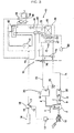
- FIG. 1 is a schematic diagram of a cogeneration system according to a first embodiment of the present invention, illustrating a state in which a heat pump type air conditioner included in the cogeneration system operates in a heating mode under a heavy-frost condition.
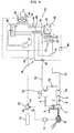
- FIG. 2 is a schematic diagram of the cogeneration system according to the first embodiment of the present invention, illustrating a state in which the heat pump type air conditioner operates in the heating mode under a non-frost condition.
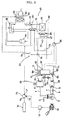
- FIG. 3 is a schematic diagram of the cogeneration system according to the first embodiment of the present invention, illustrating a state in which the heat pump type air conditioner operates in the heating mode under a light-frost condition.
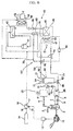
- FIG. 4 is a schematic diagram of the cogeneration system according to the first embodiment of the cogeneration system, illustrating a state in which the heat pump type air conditioner operates in a cooling mode.
- the cogeneration system includes an engine 2, a generator 10 connected to an output shaft of the engine 2 to generate electricity, an engine-cooling heat exchanger 20 to absorb heat from cooling water used to cool the engine 2, and an exhaust gas heat exchanger 30 to absorb heat from exhaust gas discharged from the engine 2.
- the cogeneration system also includes a heat pump type air conditioner 40, which includes a compressor 41, a directional valve 42, an indoor heat exchanger 43, an expansion device 44, and an outdoor heat exchanger 45.
- the cogeneration system further includes a pre-heater 50 to pre-heat air blown toward the outdoor heat exchanger 45 during a heating operation of the heat pump type air conditioner 40, an auxiliary evaporator 60 to evaporate a refrigerant emerging from the outdoor heat exchanger 45 during the heating operation of the heat pump type air conditioner 40, and a heat transfer means 70 to transfer heat from the engine-cooling heat exchanger 20 and heat from the exhaust gas heat exchanger 30 to at least one of the pre-heater 50 and auxiliary evaporator 60 while controlling the amount of the transferred heat in accordance with the frost condition of the outdoor heat exchanger 45.
- a pre-heater 50 to pre-heat air blown toward the outdoor heat exchanger 45 during a heating operation of the heat pump type air conditioner 40
- an auxiliary evaporator 60 to evaporate a refrigerant emerging from the outdoor heat exchanger 45 during the heating operation of the heat pump type air conditioner 40
- a heat transfer means 70 to transfer heat from the engine-cooling heat exchanger 20 and heat from
- the engine 2 includes a combustion chamber defined in the interior of the engine 2.
- a fuel tube 3 and an exhaust tube 4 are connected to the engine 2.
- the fuel tube 3 is adapted to supply fuel such as liquefied gas or liquefied petroleum gas into the combustion chamber.
- the exhaust tube 4 is adapted to guide exhaust gas discharged from the combustion chamber.
- the exhaust tube 4 is arranged between the engine 2 and the exhaust gas heat exchanger 30.
- the engine-cooling heat exchanger 20 is connected to the engine 2 via cooling water circulation conduits 7 and 8 so that the cooling water, which is heated while cooling the engine 2, transfers heat to the engine-cooling heat exchanger 20 while passing through the engine-cooling heat exchanger 20, and is then again circulated into the engine 2.
- a cooling water circulation pump 9 is connected to one of the engine 2, engine-cooling heat exchanger 20, and cooling water circulation conduits 7 and 8.
- the generator 10 may be an AC generator or a DC generator.
- An inverter 12 is coupled to the generator 10 to perform DC/AC conversion on electricity generated from the generator 10.
- the above-described cogeneration system may be implemented to supply only the electricity generated from the generator 10 to the heat pump type air conditioner 40 or to selectively supply the electricity generated from the generator 10 or electricity supplied from an external electricity supply source 14 to the heat pump type air conditioner 40.
- the following description will be given only in conjunction with the case in which the electricity generated from the generator 10 or electricity supplied from an external electricity supply source 14 is selectively supplied to the heat pump type air conditioner 40.
- An electricity supply switch 16 is connected to the external electricity supply source 14.
- the electricity supply switch 16 has an output terminal 17 connected to the heat pump type air conditioner 40 via an electricity feed line.
- the electricity supply switch 16 also has a first input terminal 18 connected to the external electricity supply source 14 via an electricity feed line, and a second input terminal 19 connected to the generator 10 via an electricity feed line.
- the electricity supply switch 16 When the electricity supply switch 16 is switched to an external electricity supply mode, the electricity feed lines of the external electricity supply source 14 and heat pump type air conditioner 40 are connected by the electricity supply switch 16. In this case, accordingly, the electricity from the external electricity supply source 14 is supplied to the heat pump type air conditioner 40.
- the electricity supply switch 16 when the electricity supply switch 16 is switched to a generator electricity supply mode, the electricity supply lines of the generator 10 and heat pump type air conditioner 40 are connected by the electricity supply switch 16. In this case, accordingly, the electricity from the generator 10 is supplied to the heat pump type air conditioner 40.
- the heat pump type air conditioner 40 further includes an indoor fan 46 to blow indoor air to the indoor heat exchanger 43, and an outdoor fan 47 to blow outdoor air to the outdoor heat exchanger 45.
- the indoor heat exchanger 43 and indoor fan 46 constitute an indoor unit 48 of the heat pump type air conditioner 40.
- the compressor 41, directional valve 42, expansion device 44, outdoor heat exchanger 45, and outdoor fan 47 constitute an outdoor unit 49 of the heat pump type air conditioner 40.
- the pre-heater 50 is arranged upstream from the outdoor heat exchanger 45 with respect to a flowing direction of outdoor air O blown toward the outdoor heat exchanger 45 such that the outdoor air O is fed to the outdoor heat exchanger 25 after being pre-heated by the pre-heater 50.
- the auxiliary evaporator 60 is arranged between the outdoor heat exchanger 45 and the directional valve 42 or between the directional valve 42 or the compressor 41 such that the refrigerant, which has been evaporated while passing through the outdoor heat exchanger 45, is circulated into the compressor 41 after being re-evaporated by the auxiliary evaporator 60.
- the heat transfer means 70 transfers heat from the engine-cooling heat exchanger 20 and heat from the exhaust gas heat exchanger 30 to the pre-heater 50, as shown in FIG. 1. Also, when the heat pump type air conditioner 40 operates in the heating mode, and the outdoor heat exchanger 45 is under a non-frost condition, the heat transfer means 70 transfers the heat from the engine-cooling heat exchanger 20 and the heat from the exhaust gas heat exchanger 30 to the auxiliary evaporator 60, as shown in FIG. 2.
- the heat transfer means 70 transfers heat from the engine-cooling heat exchanger 20 and heat from the exhaust gas heat exchanger 30 to the pre-heater 50 and auxiliary evaporator 60, respectively, as shown in FIG. 3.
- the heat transfer means 70 includes pre-heater circulation conduits 71 and 72 to guide a heat medium to be circulated around the engine-cooling heat exchanger 20, exhaust gas heat exchanger 30, and pre-heater 50, auxiliary evaporator circulation conduits 73 and 74 to guide the heat medium to be circulated around the engine-cooling heat exchanger 20, exhaust gas heat exchanger 39, and auxiliary evaporator 60, and a heat medium circulation pump 75 to pump the heat medium for circulation of the heat medium.
- the heat transfer means 70 also includes a control valve 76 to control the amount of the heat transfer circulated through the pre-heater circulation conduits 71 and 72 and auxiliary evaporator circulation conduits 73 and 74, an outdoor temperature sensor 78 to measure outdoor temperature or the temperature of the outdoor heat exchanger 45, and a controller to control the control valve 76 in accordance with the outdoor temperature measured by the outdoor temperature sensor 78.
- the auxiliary evaporator circulation conduits 73 and 74 are branched from the pre-heater circulation conduit 71 or 72 upstream from the pre-heater 50 such that the auxiliary evaporator circulation conduits 73 and 74 are bypassed through the auxiliary evaporator 60.
- the auxiliary evaporator circulation conduits 73 and 74 are joined to the pre-heater circulation conduit 71 or 72 downstream from the pre-heater 50.
- the heat medium circulation pump 75 is directly connected to one of the engine-cooling heat exchanger 20, exhaust gas heat exchanger 30, and pre-heater circulation conduits 71 and 72. The following description will be given only in conjunction with the case in which the heat medium circulation pump 75 is directly connected to the pre-heater circulation conduit 71 or 72 between the engine-cooling heat exchanger 20 and the exhaust gas heat exchanger 40.
- control valve 76 is arranged at a branching region where the auxiliary evaporator circulation conduits 73 and 74 are branched from the pre-heater circulation conduit 71 or 72 to control the amount of the heat medium circulated through the auxiliary evaporator circulation conduits 73 and 74 or pre-heater circulation conduits 71 and 72
- such control valves may be arranged at the pre-heater circulation conduits 71 and 72 and auxiliary evaporator circulation conduits 73 and 74, respectively, to control respective heat medium amounts circulated through the circulation conduits.
- the following description will be given only in conjunction with the case in which only one control valve 76 is arranged at a branching region where the auxiliary evaporator circulation conduits 73 and 74 are branched from the pre-heater circulation conduit 71 or 72.
- the outdoor temperature sensor 78 may be mounted to the outdoor unit 49 such that the outdoor temperature sensor 78 is spaced apart from the outdoor heat exchanger 45, so as to measure the temperature of outdoor air.
- the outdoor temperature sensor 78 may be mounted to the outdoor heat exchanger 45 to measure the temperature of the outdoor heat exchanger 45. The following description will be given only in conjunction with the case in which the outdoor temperature sensor 78 is used to measure the temperature of the outdoor air.
- the control unit 80 controls the control valve 78 to operate in a pre-heater circulation mode, as shown in FIG. 1.
- the control unit 80 controls the control valve 78 to operate in an auxiliary evaporator circulation mode, as shown in FIG. 2.
- the control unit 80 controls the control valve 78 to operate in a common mode, as shown in FIG. 3.
- Exhaust gas which is discharged from the engine 2, is fed to the exhaust gas heat exchanger 30 via the exhaust tube 4, and is then discharged to the atmosphere after releasing its heat into the exhaust gas heat exchanger 30.
- the cooling water circulation pump 9 When the cooling water circulation pump 9 operates during the operation of the engine 2, the cooling water, which is heated while cooling the engine 2, is fed to the engine-cooling heat exchanger 20 via the cooling water circulation conduit 7, and is then circulated into the engine 2 via the cooling water circulation conduit 8 after releasing its heat into the engine-cooling heat exchanger 20.
- the temperature sensor 78 measures outdoor temperature, and outputs a signal indicative of the measured outdoor temperature to the controller 80.
- the control unit 80 controls the control valve 78 to operate in the pre-heater circulation mode, as shown in FIG. 1.
- the control unit 80 also controls the heat medium circulation pump 75 to be driven, the directional valve 42 to be switched to the heating mode, and the compressor 41 to be driven.
- control valve 78 When the control valve 78 operates in the pre-heater circulation mode, the pre-heater circulation conduits 71 and 72 are opened, and the auxiliary evaporator circulation conduits 73 and 74 are closed.
- the heat medium circulation pump 75 When the heat medium circulation pump 75 operates under the condition in which the pre-heater circulation conduits 71 and 72 are opened, and the auxiliary evaporator circulation conduits 73 and 74 are closed, the heat medium absorbs heat from the engine-cooling heat exchanger 20 while passing around the engine-cooling heat exchanger 20, and also absorbs heat from the exhaust gas heat exchanger 30 while passing around the exhaust gas heat exchanger 30.
- the heat medium After absorbing the heat of the engine-cooling heat exchanger 20 and exhaust gas heat exchanger 30, the heat medium is fed to the pre-heater 50 via the pre-heater circulation conduit 71, so that the heat medium transfers the absorbed heat to the pre-heater 50. Thereafter, the heat medium is circulated around the engine-cooling heat exchanger 20 via the pre-heater circulation conduit 72.
- the directional valve 42 When the directional valve 42 is switched to a heating mode in the procedure in which the waste heat of the engine-cooling heat exchanger 20 and exhaust gas heat exchanger 30 is recovered by the heat medium, and the recovered waste heat is transferred to the pre-heater 50, and the compressor 41 operates, the compressor 41 compresses low-temperature and low-pressure refrigerant gas, thereby changing the refrigerant gas into a high-temperature and high-pressure state.
- the high-temperature and high-pressure refrigerant gas is fed into the indoor heat exchanger 43 via the directional valve 42, and discharges its heat into indoor air while passing through the indoor heat exchanger 43, so that the refrigerant gas is condensed into a liquid state.
- the condensed refrigerant is expanded while passing through the expansion device 44, and is then fed into the outdoor heat exchanger 45.
- the expanded refrigerant absorbs heat from outdoor air O while passing through the outdoor heat exchanger 45, so that the refrigerant is evaporated.
- the evaporated refrigerant passes through the auxiliary evaporator 60 without any heat exchange or any state change, and is subsequently circulated into the compressor 41 via the directional valve 42.
- the outdoor air O blown to the outdoor heat exchanger 45 is heated by the pre-heater 50, and then passes around the outdoor heat exchanger 45 to prevent the outdoor heat exchanger 45 from being frosted.
- the control unit 80 controls the control valve 78 to operate in an auxiliary evaporator circulation mode, as shown in FIG. 2.
- the control unit 80 also controls the heat medium circulation pump 75 to be driven, the directional valve 42 to be switched to the heating mode, and the compressor 41 to be driven.
- control valve 78 When the control valve 78 operates in the auxiliary evaporator circulation mode, the pre-heater circulation conduits 71 and 72 are closed, and the auxiliary evaporator circulation conduits 73 and 74 are opened.
- the heat medium circulation pump 75 When the heat medium circulation pump 75 operates under the condition in which the pre-heater circulation conduits 71 and 72 are closed, and the auxiliary evaporator circulation conduits 73 and 74 are opened, the heat medium absorbs heat from the engine-cooling heat exchanger 20 while passing around the engine-cooling heat exchanger 20, and subsequently absorbs heat from the exhaust gas heat exchanger 30 while passing around the exhaust gas heat exchanger 30.
- the heat medium After absorbing the heat of the engine-cooling heat exchanger 20 and exhaust gas heat exchanger 30, the heat medium is fed to the auxiliary evaporator 60 via the auxiliary evaporator circulation conduit 73, so that the heat medium transfers the absorbed heat to the auxiliary evaporator 60. Thereafter, the heat medium is circulated around the engine-cooling heat exchanger 20 via the auxiliary evaporator circulation conduit 74.
- the directional valve 42 When the directional valve 42 is switched to a heating mode in the procedure in which the waste heat of the engine-cooling heat exchanger 20 and exhaust gas heat exchanger 30 is recovered by the heat medium, and the recovered waste heat is transferred to the auxiliary evaporator 60, and the compressor 41 operates, the compressor 41 compresses low-temperature and low-pressure refrigerant gas, thereby changing the refrigerant gas into a high-temperature and high-pressure state.
- the high-temperature and high-pressure refrigerant gas is fed into the indoor heat exchanger 43 via the directional valve 42, and discharges its heat into indoor air while passing through the indoor heat exchanger 43, so that the refrigerant gas is condensed into a liquid state.
- the condensed refrigerant is expanded while passing through the expansion device 44, and is then fed into the outdoor heat exchanger 45.
- the expanded refrigerant absorbs heat from outdoor air O while passing through the outdoor heat exchanger 45, so that the refrigerant is evaporated.
- the evaporated refrigerant is further evaporated by the auxiliary evaporator 60 while passing through the auxiliary evaporator 60, and is subsequently introduced into the compressor 41 via the directional valve 42. Thus, circulation of the refrigerant 41 is achieved.
- the refrigerant 41 introduced into the compressor 41 repeats the above-described circulation, so that the refrigerant 41 is repeatedly evaporated. As a result, it is possible to achieve an improvement in the heating performance of the indoor heat exchanger 42 and a reduction in the power consumption of the compressor 41 in accordance with the repeated evaporation of the refrigerant 41.
- the control unit 80 controls the control valve 78 to operate in a common mode, as shown in FIG. 3.
- the control unit 80 also controls the heat medium circulation pump 75 to be driven, the directional valve 42 to be switched to the heating mode, and the compressor 41 to be driven.
- both the pre-heater circulation conduits 71 and 72 and the auxiliary evaporator circulation conduits 73 and 74 are opened.
- the heat medium circulation pump 75 When the heat medium circulation pump 75 operates under the condition in which the pre-heater circulation conduits 71 and 72 and auxiliary evaporator circulation conduits 73 and 74 are opened, the heat medium absorbs heat from the engine-cooling heat exchanger 20 while passing around the engine-cooling heat exchanger 20, and subsequently absorbs heat from the exhaust gas heat exchanger 30 while passing around the exhaust gas heat exchanger 30.
- the heat medium After absorbing the heat of the engine-cooling heat exchanger 20 and exhaust gas heat exchanger 30, the heat medium is distributed into the pre-heater circulation conduits 71 and 72 and auxiliary evaporator circulation conduits 73 and 74.
- a part of the heat medium is fed to the pre-heater 50 via the pre-heater circulation conduit 71, so that the heat medium transfers the absorbed heat to the pre-heater 50.
- the heat medium is circulated around the engine-cooling heat exchanger 20 via the pre-heater circulation conduit 72.
- the remaining part of the heat medium is fed to the auxiliary evaporator 60 via the auxiliary evaporator circulation conduit 73, so that the heat medium transfers the absorbed heat to the auxiliary evaporator 60.
- the heat medium is circulated around the engine-cooling heat exchanger 20 via the auxiliary evaporator circulation conduit 74.
- the waste heat of the engine-cooling heat exchanger 20 and exhaust gas heat exchanger 30 is partially used to prevent the indoor heat exchanger 45 from being frosted, and is partially used to improve the heating performance of the indoor heat exchanger 42.
- the controller 80 stops the heat medium circulation pump 75, irrespective of the temperature measured by the temperature sensor 78, when the heat pump type air conditioner 40 is to operate in a cooling mode. In this case, the controller 80 also switches the directional valve 42 to a cooling mode, and also operates the compressor 41.
- the compressor 41 compresses low-temperature and low-pressure refrigerant gas, thereby changing the refrigerant gas into a high-temperature and high-pressure state.
- the high-temperature and high-pressure refrigerant gas passes through the auxiliary evaporator 60 via the directional valve 42 without any heat exchange with the auxiliary evaporator 60.
- the refrigerant gas is then fed into the outdoor heat exchanger 45, and discharges its heat into outdoor air O while passing through the outdoor heat exchanger 45, so that the refrigerant gas is condensed into a liquid state.
- the condensed refrigerant is expanded while passing through the expansion device 44, and is then fed into the indoor heat exchanger 43.
- the expanded refrigerant absorbs heat from indoor air I while passing through the indoor heat exchanger 43, so that the refrigerant is evaporated.
- the evaporated refrigerant is circulated into the compressor 41 via the directional valve 42.
- the heat medium circulation pump 75 when the heat medium circulation pump 75 is in a stopped state, the heat of the engine-cooling heat exchanger 20 and exhaust gas heat exchanger 30 is discharged to the atmosphere without being transferred to the pre-heater 50 or auxiliary evaporator 60.
- FIG. 5 is a schematic diagram of a cogeneration system according to a second embodiment of the present invention, illustrating a state in which a heat pump type air conditioner included in the cogeneration system operates in a cooling mode.
- the cogeneration system includes a radiator 90 to radiate heat, and a heat transfer means 70' to transfer heat from the engine-cooling heat exchanger 20 to the radiator 90 when the heat pump type air conditioner 40 operates in a cooling mode.
- the radiator 90 includes a radiator heat exchanger 92 connected to the heat transfer means 70', and a radiator fan 94 to blow the outdoor air O to the radiator heat exchanger 92.
- the heat transfer means 70' includes pre-heater circulation conduits 71 and 72 to guide a heat medium to be circulated around the engine-cooling heat exchanger 20, exhaust gas heat exchanger 30, and pre-heater 50, auxiliary evaporator circulation conduits 73 and 74 to guide the heat medium to be circulated around the engine-cooling heat exchanger 20, exhaust gas heat exchanger 30, and auxiliary evaporator 60, and a heat medium circulation pump 75 to pump the heat medium for circulation of the heat medium.
- the heat transfer means 70' also includes a control valve 76 to control the amount of the heat transfer circulated through the pre-heater circulation conduits 71 and 72 and auxiliary evaporator circulation conduits 73 and 74, an outdoor temperature sensor 78 to measure outdoor temperature or the temperature of the outdoor heat exchanger 45, radiator circulation conduits 81 and 82 bypassed from pre-heater circulation conduits 71 and 72 to guide the heat medium to be circulated around the engine-cooling heat exchanger 20 and radiator heat exchanger 92, a first valve 84 arranged at a branching region where the radiator circulation conduits 81 and 82 are branched from the pre-heater circulation conduit 71 or 72, to alternately open/close the pre-heater circulation conduits 71 and 72 and the radiator circulation conduits 81 and 82, and a second valve 86 arranged at a joining region where the radiator circulation conduits 73 and 74 are joined to the pre-heater circulation conduit 71 or 72, to alternately open/close the pre-heater
- the heat transfer means 70' further includes a controller 80 to control the first and second valves 84 and 86 in accordance with whether the heat pump type air conditioner 40 operates in a cooling mode or in a heating mode, and to control the control valve 76 in accordance with the outdoor temperature measured by the outdoor temperature sensor 78.
- the heat medium circulation pump 75 is directly connected to the pre-heater circulation conduit 71 or 72 between the engine-cooling heat exchanger 20 and the exhaust gas heat exchanger 30.
- the radiator circulation conduits 81 and 82 are branched from the pre-heater circulation conduit 71 or 72 between the heat medium circulation pump 75 and the exhaust gas heat exchanger 30 such that the radiator circulation conduits 81 and 82 are bypassed around the radiator heat exchanger 92.
- the radiator circulation conduits 81 and 82 are joined to the pre-heater circulation conduit 71 or 72 upstream from the engine-cooling heat exchanger 20.
- the first and second valves 84 and 86 operate in a pre-heater circulation mode to open the pre-heater circulation conduits 71 and 72 and to close the radiator circulation conduits 81 and 82.
- the first and second valves 84 and 86 operate in a radiator circulation mode to close the pre-heater circulation conduits 71 and 72 and to open the radiator circulation conduits 81 and 82.
- the cogeneration system of the second embodiment has the same configuration and functions as those of the first embodiment, except for the radiator 90, radiator circulation conduits 81 and 82, first valve 84 and second valve 86. Accordingly, the constituent elements of the second embodiment respectively corresponding to those of the first embodiment are designated by the same reference numerals, and no detailed description thereof will be given.
- the heat medium circulation pump 75 is driven, and the first and second valves 84 and 86 are controlled to operate in a radiator circulation mode. Also, the radiator fan 94 is driven, the directional valve is switched to a cooling mode, and the compressor 41 is driven.
- the heat medium circulation pump 75 When the first and second valves 84 and 86 are controlled to operate in the radiator circulation mode, and the heat medium circulation pump 75 is driven, the heat medium absorbs heat from the engine-cooling heat exchanger 20 while passing through the engine-cooling heat exchanger 20. Subsequently, the heat medium is fed to the radiator heat exchanger 92 via the radiator circulation conduit 81.
- the heat medium fed to the radiator heat exchanger 92 transfers the heat absorbed from the engine-cooling heat exchanger 20 to the radiator heat exchanger 92.
- the heat medium is then circulated around the engine-cooling heat exchanger 20 via the radiator circulation conduit 82.
- the compressor 41 compresses low-temperature and low-pressure refrigerant gas, thereby changing the refrigerant gas into a high-temperature and high-pressure state.
- the high-temperature and high-pressure refrigerant gas is fed into the outdoor heat exchanger 45 via the directional valve 42, and discharges its heat into outdoor air while passing through the outdoor heat exchanger 45, so that the refrigerant gas is condensed into a liquid state.
- the condensed refrigerant is expanded while passing through the expansion device 44, and is then fed into the indoor heat exchanger 43.
- the expanded refrigerant absorbs heat from indoor air I while passing through the indoor heat exchanger 43, so that the refrigerant is evaporated.
- the evaporated refrigerant is circulated into the compressor 41 via the directional valve 42.
- the exhaust gas heat exchanger 30 discharges the heat absorbed from the exhaust gas to the atmosphere.
- the heat medium circulation pump 75 is driven, and the first and second valves 84 and 86 are controlled to operate in a pre-heater circulation mode.
- the directional valve is switched to a heating mode, the compressor 41 is driven, and the control valve 76 is controlled to operate in a pre-heater circulation mode, an auxiliary evaporator circulation mode, or a common mode in accordance with the outdoor temperature measured by the temperature sensor 78 or the temperature of the outdoor heat exchanger 45.
- the heat medium absorbs heat from the engine-cooling heat exchanger 20 while passing through the engine-cooling heat exchanger 20. Subsequently, the heat medium also absorbs heat from the exhaust gas heat exchanger 30 while passing through the exhaust gas heat exchanger 30.
- the heat medium which has absorbed the heat of the engine-cooling heat exchanger 20 and exhaust gas heat exchanger 30, transfers the absorbed heat only to the pre-heater 50, only to the auxiliary evaporator 60, or to both the pre-heater 50 and the auxiliary evaporator 60.
- the switching operation of the directional valve 42 to the heating mode, the operation of the compressor 41, and the control operation of the control valve 76 are the same as those of the first embodiment, so that no detailed description thereof will be given.
- FIG. 6 is a schematic diagram of a cogeneration system according to a third embodiment of the present invention.
- the cogeneration system includes a heat transfer means 70" to transfer only the heat of the engine-cooling heat exchanger 20 to the pre-heater 50 or to the auxiliary evaporator 60 during a heating operation of the heat pump type air conditioner 40.
- the heat transfer means 70" includes pre-heater circulation conduits 71" and 72", which connect the engine-cooling heat exchanger 20 and the pre-heater 50 to guide a heat medium to be circulated around the engine-cooling heat exchanger 20 and pre-heater 50 without passing around the exhaust gas heat exchanger 30.
- the cogeneration system of the third embodiment has the same configuration and functions as those of the first embodiment or second embodiment, except for the pre-heater circulation conduits 71" and 72". Accordingly, the constituent elements of the third embodiment respectively corresponding to those of the first embodiment or second embodiment are designated by the same reference numerals, and no detailed description thereof will be given.
- the heat of the exhaust gas heat exchanger 30 is discharged to the atmosphere without being transferred to the pre-heater 50 or auxiliary evaporator 60.
- FIG. 7 is a schematic diagram of a cogeneration system according to a fourth embodiment of the present invention.
- the cogeneration system includes a plurality of engines 2, 2'....
- the cogeneration system also includes a plurality of generators 10, 10'... connected to respective shafts of the engines 2, 2'....
- the cogeneration system of the fourth embodiment has the same configuration and functions as those of any one of the first through third embodiments, except for the engines 2, 2'... and generators 10, 10'.... Accordingly, the constituent elements of the fourth embodiment respectively corresponding to those of any one of the first through third embodiments are designated by the same reference numerals, and no detailed description thereof will be given.
- One or more of the engines 2, 2'... operate in accordance with the load to be cooled or heated.
- Fuel tubes 3, 3'... are connected to respective engines 2, 2'.... Also, pairs of cooling water circulation conduits 7 and 8, 7' and 8' ... are connected to respective engines 2, 2'....
- the cooling water circulation conduits 7 and 8, 7' and 8'... are connected in parallel.
- Cooling water circulation pumps 9, 9'... are directly connected to the cooling water circulation conduit 7 or 8, cooling water circulation conduit 7' or 8'..., respectively.
- the cogeneration system of the fourth embodiment has the same configuration and functions as those of any one of the first through third embodiments, except that a plurality of engines 2, 2'..., a plurality of fuel tubes 3, 3'..., a plurality of exhaust gas tubes 4, 4'..., a plurality of cooling water circulation conduits 7, 8, 7', 8'..., and a plurality of generators 10, 10'... are used. Accordingly, the constituent elements of the fourth embodiment respectively corresponding to those of any one of the first through third embodiments are designated by the same reference numerals, and no detailed description thereof will be given.
- FIG. 8 is a schematic diagram of a cogeneration system according to a fifth embodiment of the present invention.
- the heat pump type air conditioner that is, the heat pump type air conditioner 40, which is included in the cogeneration system, is of a multi-type. That is, the heat pump type air conditioner 40 includes a plurality of indoor units 48, 48'..., and a single outdoor unit 49.
- the indoor units 48, 48'... include indoor heat exchangers 43, 43'..., which are connected in parallel, respectively.
- the indoor units 48, 48'... also include indoor blowers 46, 46'..., respectively.
- the cogeneration system of this embodiment has the same configuration and functions as those of any one of the first through fourth embodiments, except that the heat pump type air conditioner 40 includes a plurality of indoor units 48, 48'..., and thus, a plurality of indoor heat exchangers 43, 43'.... Accordingly, the constituent elements of the fifth embodiment respectively corresponding to those of any one of the first through fourth embodiments are designated by the same reference numerals, and no detailed description thereof will be given.
- FIG. 9 is a schematic diagram of a cogeneration system according to a sixth embodiment of the present invention.
- the heat pump type air conditioner that is, the heat pump type air conditioner 40, which is included in the cogeneration system, includes a plurality of indoor units 48, 48'..., and a plurality of outdoor units 49, 49'....
- refrigerant conduits respectively included in the indoor units 48, 48'... may be connected in parallel.
- Refrigerant conduits respectively included in the outdoor units 49, 49'... may also be connected in parallel.
- the indoor units 48, 48'... include respective indoor heat exchangers 43, 43'..., and respective indoor blowers 46, 46'....
- the outdoor units 49, 49'... include respective compressors 41, 41'..., directional valves 42, 42'..., respective expansion devices 44, 44'..., respective outdoor heat exchangers 45, 45'..., and respective outdoor blowers 47, 47'....
- the outdoor units 49, 49'... also include pre-heaters 50, 50'..., auxiliary evaporators 60, 60'..., and temperature sensors 78, 78'..., respectively.
- Each of the pre-heaters 50, 50'... are arranged upstream from an associated one of the outdoor heat exchangers 45, 45'....
- Pairs of pre-heater circulation conduits 71 and 72, 71' and 72'..., which are connected in parallel, are connected to respective pre-heaters 50, 50'.... to guide a heat medium to be circulated around the pre-heaters 50, 50'....
- Each of the auxiliary evaporators 60, 60'... may be arranged between an associated one of the outdoor heat exchangers 45, 45'... and an associated one of the directional valves 42, 42'..., or may be arranged between the associated one of the directional valves 42, 42'... and an associated one of the compressors 41, 41'....
- Pairs of auxiliary evaporator circulation conduits 73 and 74, 73' and 74'..., which are connected in parallel, are connected to respective auxiliary evaporators 60, 60'.... to guide a heat medium to be circulated around the auxiliary evaporators 60, 60'....
- the cogeneration system of this embodiment has the same configuration and functions as those of any one of the first through fifth embodiments, except that the heat pump type air conditioner 40 includes a plurality of indoor units 48, 48'..., a plurality of outdoor units 49, 49'..., a plurality of pre-heaters 50, 50'..., a plurality of pre-heater circulation conduits 71, 72, 71', 72'..., a plurality of auxiliary evaporators 60, 60'..., and a plurality of auxiliary evaporator circulation conduits 73, 74, 73', 74'.... Accordingly, the constituent elements of the sixth embodiment respectively corresponding to those of any one of the first through fifth embodiments are designated by the same reference numerals, and no detailed description thereof will be given.
- the cogeneration system according to any one of the above-described embodiments of the present invention has various effects.
- the cogeneration system according to the present invention has an advantage in that waste heat of an engine is supplied, during a heating operation of the heat pump type air conditioner, to the pre-heater arranged to pre-heat outdoor air blown toward the outdoor heat exchanger or to the auxiliary evaporator arranged to evaporate refrigerant emerging from the outdoor heat exchanger, so that the cogeneration system exhibits a high energy efficiency.
- the heat of exhaust gas discharged from the engine is not transferred to the radiator during a cooling operation of the heat pump type air conditioner.
- the heat pump type air conditioner only the heat of cooling water used to cool the engine is transferred to the radiator so that the transferred heat is discharged from the radiator. Accordingly, there are advantages in that it is possible to minimize the size of the radiator and the amount of air blown to the radiator, and to reduce costs and noise.
- waste heat is selectively transferred to the pre-heater and auxiliary evaporator in accordance with frost conditions of the outdoor heat exchanger included in the heat pump type air conditioner, so that it is possible to enable the cogeneration system to positively cope with ambient temperature conditions, and to maximize the heating performance of the heat pump type air conditioner.
Landscapes
- Engineering & Computer Science (AREA)
- Mechanical Engineering (AREA)
- General Engineering & Computer Science (AREA)
- Physics & Mathematics (AREA)
- Thermal Sciences (AREA)
- Chemical & Material Sciences (AREA)
- Combustion & Propulsion (AREA)
- Heat-Pump Type And Storage Water Heaters (AREA)
- Air Conditioning Control Device (AREA)
- Compression-Type Refrigeration Machines With Reversible Cycles (AREA)
Applications Claiming Priority (1)
| Application Number | Priority Date | Filing Date | Title |
|---|---|---|---|
| KR1020040064806A KR100600753B1 (ko) | 2004-08-17 | 2004-08-17 | 열병합 발전 시스템 |
Publications (3)
| Publication Number | Publication Date |
|---|---|
| EP1628099A2 true EP1628099A2 (de) | 2006-02-22 |
| EP1628099A3 EP1628099A3 (de) | 2011-05-11 |
| EP1628099B1 EP1628099B1 (de) | 2012-08-22 |
Family
ID=36080349
Family Applications (1)
| Application Number | Title | Priority Date | Filing Date |
|---|---|---|---|
| EP05000913A Not-in-force EP1628099B1 (de) | 2004-08-17 | 2005-01-18 | Wärme-Kraft-System und Verfahren für dessen Steuerung |
Country Status (4)
| Country | Link |
|---|---|
| US (1) | US7174727B2 (de) |
| EP (1) | EP1628099B1 (de) |
| KR (1) | KR100600753B1 (de) |
| CN (1) | CN100338414C (de) |
Cited By (4)
| Publication number | Priority date | Publication date | Assignee | Title |
|---|---|---|---|---|
| EP2434234A3 (de) * | 2010-09-22 | 2013-12-18 | Aisin Seiki Kabushiki Kaisha | Klimaanlage |
| EP2629031A3 (de) * | 2012-02-14 | 2018-07-11 | Lg Electronics Inc. | Gaswärmepumpensystem |
| US20180372333A1 (en) * | 2017-06-27 | 2018-12-27 | Imby Energy, Inc. | Cogeneration systems and methods for generating heating and electricity |
| US11041631B2 (en) * | 2019-01-15 | 2021-06-22 | Averill Partners, Llc | Installation of combined heat and power systems |
Families Citing this family (12)
| Publication number | Priority date | Publication date | Assignee | Title |
|---|---|---|---|---|
| US7503184B2 (en) * | 2006-08-11 | 2009-03-17 | Southwest Gas Corporation | Gas engine driven heat pump system with integrated heat recovery and energy saving subsystems |
| WO2011152217A1 (ja) * | 2010-05-31 | 2011-12-08 | 日本電気株式会社 | ディスプレイ装置 |
| GB2481583A (en) * | 2010-06-28 | 2012-01-04 | Smith S Environmental Products Ltd | Heat pump installation |
| EP2460928B1 (de) * | 2010-12-02 | 2014-02-26 | Electrolux Home Products Corporation N.V. | Verfahren zur Bedienung eines Wärmepumpentrockners und Wärmepumpentrockner |
| CN102331027B (zh) * | 2011-07-27 | 2013-05-01 | 双良节能系统股份有限公司 | 热电厂回收主辅机冷凝废热热网回水串联水水式供热系统 |
| CN102331025B (zh) * | 2011-07-27 | 2013-05-01 | 双良节能系统股份有限公司 | 热电厂回收主、辅机冷凝废热汽水式供热系统 |
| ES2773020T3 (es) | 2011-09-02 | 2020-07-09 | Carrier Corp | Sistema de refrigeración y procedimiento de refrigeración que proporciona la recuperación de calor |
| EP2573252B1 (de) * | 2011-09-26 | 2014-05-07 | Electrolux Home Products Corporation N.V. | Wäschebehandlungsvorrichtung mit Wärmepumpe |
| US11050249B2 (en) | 2012-03-23 | 2021-06-29 | Concentric Power, Inc. | Systems and methods for power cogeneration |
| US9388766B2 (en) | 2012-03-23 | 2016-07-12 | Concentric Power, Inc. | Networks of cogeneration systems |
| DE102018105722A1 (de) * | 2018-03-13 | 2019-09-19 | Eisenmann Se | Konditioniervorrichtung, Behandlungsanlage mit einer Konditioniervorrichtung und Verfahren zu Betreiben einer Konditioniervorrichtung |
| CN110154691B (zh) * | 2019-05-27 | 2020-08-04 | 安徽江淮汽车集团股份有限公司 | 汽车热管理系统及方法 |
Citations (5)
| Publication number | Priority date | Publication date | Assignee | Title |
|---|---|---|---|---|
| JPS57161437A (en) * | 1981-03-30 | 1982-10-05 | Tokyo Gas Co Ltd | Engine-driven heat pump system |
| US4697434A (en) * | 1985-10-17 | 1987-10-06 | Mitsubishi Denki Kabushiki Kaisha | Prime mover driven air-conditioning and hot-water supplying system |
| JP2002070646A (ja) * | 2000-09-04 | 2002-03-08 | Kubota Corp | 熱電併給システム |
| EP1202005A2 (de) * | 2000-10-30 | 2002-05-02 | Mitsubishi Heavy Industries, Ltd. | Aussenwärmeaustauscheinheit, Ausseneinheit und Klimagerät der Art einer Gaswärmepumpe |
| EP1288592A2 (de) * | 2001-08-31 | 2003-03-05 | Mitsubishi Heavy Industries, Ltd. | Klimaanlage mit Abgaswärmepumpe, Heizvorrichtung mit Kühlwasser eines Verbrennungsmotors, und Verfahren zum Betrieb einer Klimaanlage mit Abgaswärmepumpe |
Family Cites Families (8)
| Publication number | Priority date | Publication date | Assignee | Title |
|---|---|---|---|---|
| JPH06272993A (ja) * | 1993-03-16 | 1994-09-27 | Osaka Gas Co Ltd | エンジン駆動冷暖房装置 |
| US5429179A (en) * | 1993-08-23 | 1995-07-04 | Gas Research Institute | Gas engine driven heat pump system having integrated heat recovery and auxiliary components |
| JPH08219585A (ja) * | 1995-02-10 | 1996-08-30 | Mitsubishi Heavy Ind Ltd | エンジン駆動式空気調和機 |
| KR970007272A (ko) * | 1995-07-31 | 1997-02-21 | 유상부 | 에너지 발란스형 소형 열병합 발전장치 |
| EP1072453B1 (de) * | 1999-07-26 | 2006-11-15 | Denso Corporation | Vorrichtung mit einem Kältemittelkreislauf |
| JP3798254B2 (ja) | 2001-03-29 | 2006-07-19 | 北海道瓦斯株式会社 | 空調方法、ヒートポンプおよび空調装置 |
| JP4774171B2 (ja) * | 2001-08-20 | 2011-09-14 | 社団法人エルピーガス協会 | 空気調和装置 |
| US6516623B1 (en) * | 2002-05-07 | 2003-02-11 | Modine Manufacturing Company | Vehicular heat pump system and module therefor |
-
2004
- 2004-08-17 KR KR1020040064806A patent/KR100600753B1/ko not_active IP Right Cessation
-
2005
- 2005-01-18 EP EP05000913A patent/EP1628099B1/de not_active Not-in-force
- 2005-01-19 US US11/037,196 patent/US7174727B2/en not_active Expired - Fee Related
- 2005-02-06 CN CNB2005100082407A patent/CN100338414C/zh not_active Expired - Fee Related
Patent Citations (5)
| Publication number | Priority date | Publication date | Assignee | Title |
|---|---|---|---|---|
| JPS57161437A (en) * | 1981-03-30 | 1982-10-05 | Tokyo Gas Co Ltd | Engine-driven heat pump system |
| US4697434A (en) * | 1985-10-17 | 1987-10-06 | Mitsubishi Denki Kabushiki Kaisha | Prime mover driven air-conditioning and hot-water supplying system |
| JP2002070646A (ja) * | 2000-09-04 | 2002-03-08 | Kubota Corp | 熱電併給システム |
| EP1202005A2 (de) * | 2000-10-30 | 2002-05-02 | Mitsubishi Heavy Industries, Ltd. | Aussenwärmeaustauscheinheit, Ausseneinheit und Klimagerät der Art einer Gaswärmepumpe |
| EP1288592A2 (de) * | 2001-08-31 | 2003-03-05 | Mitsubishi Heavy Industries, Ltd. | Klimaanlage mit Abgaswärmepumpe, Heizvorrichtung mit Kühlwasser eines Verbrennungsmotors, und Verfahren zum Betrieb einer Klimaanlage mit Abgaswärmepumpe |
Cited By (8)
| Publication number | Priority date | Publication date | Assignee | Title |
|---|---|---|---|---|
| EP2434234A3 (de) * | 2010-09-22 | 2013-12-18 | Aisin Seiki Kabushiki Kaisha | Klimaanlage |
| EP2629031A3 (de) * | 2012-02-14 | 2018-07-11 | Lg Electronics Inc. | Gaswärmepumpensystem |
| US20180372333A1 (en) * | 2017-06-27 | 2018-12-27 | Imby Energy, Inc. | Cogeneration systems and methods for generating heating and electricity |
| US20180372337A1 (en) * | 2017-06-27 | 2018-12-27 | Imby Energy, Inc. | Cogeneration systems and methods for generating heating and electricity |
| US11041637B2 (en) * | 2017-06-27 | 2021-06-22 | Imby Energy, Inc. | Cogeneration systems and methods for generating heating and electricity |
| US11041635B2 (en) * | 2017-06-27 | 2021-06-22 | Imby Energy, Inc. | Cogeneration systems and methods for generating heating and electricity |
| US11041636B2 (en) * | 2017-06-27 | 2021-06-22 | Imby Energy, Inc. | Cogeneration systems and methods for generating heating and electricity |
| US11041631B2 (en) * | 2019-01-15 | 2021-06-22 | Averill Partners, Llc | Installation of combined heat and power systems |
Also Published As
| Publication number | Publication date |
|---|---|
| US7174727B2 (en) | 2007-02-13 |
| CN100338414C (zh) | 2007-09-19 |
| US20060037342A1 (en) | 2006-02-23 |
| CN1737464A (zh) | 2006-02-22 |
| KR20060016388A (ko) | 2006-02-22 |
| EP1628099B1 (de) | 2012-08-22 |
| EP1628099A3 (de) | 2011-05-11 |
| KR100600753B1 (ko) | 2006-07-14 |
Similar Documents
| Publication | Publication Date | Title |
|---|---|---|
| US7174727B2 (en) | Cogeneration system and method for controlling the same | |
| US7600695B2 (en) | Cogeneration system and method for controlling the same | |
| US7170191B2 (en) | Electricity generating and air conditioning system with water heater | |
| US7275382B2 (en) | Cogeneration system | |
| US20060037348A1 (en) | Cogeneration system | |
| US7305841B2 (en) | Cogeneration system | |
| US20060037347A1 (en) | Electricity generating and air conditioning system | |
| US7145258B2 (en) | Electricity generating and air conditioning system | |
| US7240503B2 (en) | Electricity generating and air conditioning system with dehumidifier | |
| EP1628091A2 (de) | Klimaanlage kombiniert mit einem elektrizitäterzeugungsystem | |
| US7305840B2 (en) | Electricity generating and air conditioning system with dehumidifier | |
| EP1628092A2 (de) | Klimaanlage kombiniert mit einem elektrizitäterzeugungsystem | |
| US7240505B2 (en) | Cogeneration system | |
| US20060123823A1 (en) | Cogeneration system | |
| EP1628097A2 (de) | Klimaanlage kombiniert mit einem elektrizitäterzeugungsystem | |
| US20060037351A1 (en) | Cogeneration system and exhaust gas heat exchanger assembly thereof | |
| US7240504B2 (en) | Cogeneration system | |
| US7243504B2 (en) | Cogeneration system | |
| US20010042374A1 (en) | Multi-energy system | |
| KR100591320B1 (ko) | 코제너레이션 시스템을 이용한 냉난방 장치 |
Legal Events
| Date | Code | Title | Description |
|---|---|---|---|
| PUAI | Public reference made under article 153(3) epc to a published international application that has entered the european phase |
Free format text: ORIGINAL CODE: 0009012 |
|
| 17P | Request for examination filed |
Effective date: 20050118 |
|
| AK | Designated contracting states |
Kind code of ref document: A2 Designated state(s): AT BE BG CH CY CZ DE DK EE ES FI FR GB GR HU IE IS IT LI LT LU MC NL PL PT RO SE SI SK TR |
|
| AX | Request for extension of the european patent |
Extension state: AL BA HR LV MK YU |
|
| PUAL | Search report despatched |
Free format text: ORIGINAL CODE: 0009013 |
|
| AK | Designated contracting states |
Kind code of ref document: A3 Designated state(s): AT BE BG CH CY CZ DE DK EE ES FI FR GB GR HU IE IS IT LI LT LU MC NL PL PT RO SE SI SK TR |
|
| AX | Request for extension of the european patent |
Extension state: AL BA HR LV MK YU |
|
| AKX | Designation fees paid |
Designated state(s): DE FR GB |
|
| GRAP | Despatch of communication of intention to grant a patent |
Free format text: ORIGINAL CODE: EPIDOSNIGR1 |
|
| RIN1 | Information on inventor provided before grant (corrected) |
Inventor name: CHUNG, BAIK YOUNG Inventor name: KO, CHEOL SOO Inventor name: HA, SIM BOK Inventor name: KIM, CHEOL MIN |
|
| RAP1 | Party data changed (applicant data changed or rights of an application transferred) |
Owner name: LG ELECTRONICS INC. |
|
| GRAS | Grant fee paid |
Free format text: ORIGINAL CODE: EPIDOSNIGR3 |
|
| GRAA | (expected) grant |
Free format text: ORIGINAL CODE: 0009210 |
|
| AK | Designated contracting states |
Kind code of ref document: B1 Designated state(s): DE FR GB |
|
| REG | Reference to a national code |
Ref country code: GB Ref legal event code: FG4D |
|
| REG | Reference to a national code |
Ref country code: DE Ref legal event code: R096 Ref document number: 602005035726 Country of ref document: DE Effective date: 20121018 |
|
| PLBE | No opposition filed within time limit |
Free format text: ORIGINAL CODE: 0009261 |
|
| STAA | Information on the status of an ep patent application or granted ep patent |
Free format text: STATUS: NO OPPOSITION FILED WITHIN TIME LIMIT |
|
| 26N | No opposition filed |
Effective date: 20130523 |
|
| REG | Reference to a national code |
Ref country code: DE Ref legal event code: R097 Ref document number: 602005035726 Country of ref document: DE Effective date: 20130523 |
|
| REG | Reference to a national code |
Ref country code: FR Ref legal event code: PLFP Year of fee payment: 12 |
|
| PGFP | Annual fee paid to national office [announced via postgrant information from national office to epo] |
Ref country code: GB Payment date: 20151214 Year of fee payment: 12 |
|
| PGFP | Annual fee paid to national office [announced via postgrant information from national office to epo] |
Ref country code: FR Payment date: 20151214 Year of fee payment: 12 |
|
| PGFP | Annual fee paid to national office [announced via postgrant information from national office to epo] |
Ref country code: DE Payment date: 20151211 Year of fee payment: 12 |
|
| REG | Reference to a national code |
Ref country code: DE Ref legal event code: R119 Ref document number: 602005035726 Country of ref document: DE |
|
| GBPC | Gb: european patent ceased through non-payment of renewal fee |
Effective date: 20170118 |
|
| REG | Reference to a national code |
Ref country code: FR Ref legal event code: ST Effective date: 20170929 |
|
| PG25 | Lapsed in a contracting state [announced via postgrant information from national office to epo] |
Ref country code: FR Free format text: LAPSE BECAUSE OF NON-PAYMENT OF DUE FEES Effective date: 20170131 |
|
| PG25 | Lapsed in a contracting state [announced via postgrant information from national office to epo] |
Ref country code: GB Free format text: LAPSE BECAUSE OF NON-PAYMENT OF DUE FEES Effective date: 20170118 Ref country code: DE Free format text: LAPSE BECAUSE OF NON-PAYMENT OF DUE FEES Effective date: 20170801 |